

Page 1
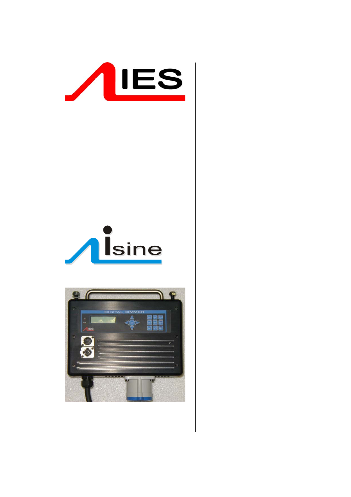
Operator Manual
Power-module
distributed dimmers
Contents:
1 Introduction ......................................................2
1.1 Product range..........................................2
1.2 New dimmer design.................................2
1.3 Distributed dimming.................................2
1.4 Key features of itec system......................2
2 Unpacking and installation ...............................2
2.1 Unpacking & checking .............................2
2.2 Positioning...............................................2
2.3 Connections.............................................2
2.4 Safety ......................................................3
3 Control panel layout .........................................3
4 Function overview ............................................4
4.1 Forward or reverse phase operation........4
4.2 Maximum and minimum levels ................4
4.3 Response speed......................................4
4.4 Non-dim operation...................................4
4.5 Local control ............................................4
4.6 Dimmer curves ........................................4
4.7 Status reporting .......................................4
4.8 Backup settings .......................................4
5. Information displays and manual control......... 5
6 Programming....................................................6
6.1 Flow diagram...........................................6
6.2 General Programming Advice..................6
6.3 Front Panel Controls................................6
6.4 General controls .....................................7
6.5 DMX programming ..................................7
6.6 Serial address..........................................8
6.7 Maximum & Minimum levels.................... 9
6.8 Response time.........................................9
6.9 Dimmer curves ........................................9
6.10 Non-Dim operation ..............................10
6.11 Maximum current.................................10
6.12 Voltage regulation................................11
6.13 Phase-On and Phase-Off .................... 12
6.14 Start Mode...........................................12
6.15 Passwords ..........................................13
6.16 Sleep mode .........................................13
6.17 Fault reporting .....................................13
6.18 Return to factory settings.....................14
7. DimSTAT.......................................................14
8. Fault finding...................................................15
8.1 Reported faults ...................................... 15
8.2 First line maintenance ...........................15
9. Specifications................................................17
10. Declaration of conformity.............................19
11. Index ...........................................................20
12. Flow chart......................................... appendix
IES PowerModule Operators’ Manual v1.4 Isine 1
Page 2

1 Introduction
1.1 Product range
This handbook describes the operation and
programming for the IES ‘PowerModule’ range of
Isine dimmers incorporating ‘Isine’ phase dimming
technology. The dimmers covered by this handbook
are
2234 PowerModule PM 80S
1 x 1200W, 1 x 80V
2102 PowerModule PM2-2S
2 x 2.5kW, 22A single phase
2235 PowerModule PM1-5S
1 x 5kW, 22A single phase
2103 PowerModule PM4-2S
4 x 2.5kW, 44A single phase
2104 PowerModule PM2-5S
2 x 5kW, 44A single phase
2236 PowerModule PM6-2S
2 x 2.5kW 22A one phase
2237 PowerModule PM3-5S
3 x 5kW 32A single phase
2105 PowerModule PM12S
1 x 12kW 52A one phase
2237 PowerModule PM24S
1 x 24kW 104A single phase
1.2 New dimmer design
The PowerModule range of dimmers represents the
most advanced dimming system available today.
The advantages of Isine dimming technology, as
developed by IES into its ‘Isine’ design, delivers lownoise, high power dimming capability with advanced
electronic measurement and control to
accommodate variations in the power supply and
load conditions. The dimmers will automatically
compensate for poor mains regulation, and will
respond to a short-circuit condition faster than any
mechanical protection device.
1.3 Distributed dimming
The high efficiency (low heat dissipation) of the
dimmer circuit, combined with its compact design,
electronic protection and sophisticated status
reporting system, makes the PowerModule ideally
suited to distributed dimming schemes where a
central dimmer room is unavailable or undesirable.
1.4 Key features of Isine system
The Isine system from IES offers low noise dimming
(both acoustic noise from lamp and dimmer as well
as electrical interference are reduced), control of a
wide range of load types, and sophisticated control
options for the broadest range of lighting dimmer
situations. Each dimmer channel can be individually
programmed either at the dimmer itself, or remotely
from a PC, and once programmed, the dimmer can
operate simply and transparently whilst being
protected against inadvertent adjustments. The
PowerModule range of dimmers is compatible with
all other IES dimmers including the Executive Isine
dimmer pack.
2 Unpacking and installation
2.1 Unpacking & checking
The PowerModule is self-contained and only
requires mounting components (two hook clamps or
‘C’ clamps and a safety bond), plus a suitable mains
input connector.
The PowerModule is packed to withstand normal
transportation, but before operating the unit, check
there is no sign of transit damage which could affect
the operation and safety of the dimmer.
2.2 Positioning
The PowerModule is an extremely versatile dimmer,
and can be located in a variety of positions. It is
designed for natural cooling, hanging by two
suspension clamps and care must be taken to
ensure adequate ventilation around the case. Note
that the full-power duty cycle is only possible if the
PowerModule is suspended in free air. If it is used
on the ground there may be insufficient ventilation
for continuous service at full power. Should the
PowerModule overheat in this condition, an internal
detection circuit will report an overheat condition and
will progressively turn-off power until a normal
operating temperature has been reached.
2.3 Connections
Note: Fit a suitably-rated plug to the cable or
connector supplied. All electrical
connections to the PowerModule must be
made by a suitably-qualified person.
IES PowerModule Operators’ Manual v1.4 Isine 2
Page 3
2.3.5 DMX data signals
All PowerModules are controlled by DMX 512
connected by a two-pair and shield high-speed data
cable with XLR 5-pin connectors (male = input;
female = output).
Pin connections are:
1 0V shield
2 DMX -
3 DMX +
4 DimSTAT -
5 DimSTAT +
The DMX network supports up to 32 PowerModules
connected to one line. For larger installations where
more DMX lines are required, the use of a DMX
booster/isolator is recommended. Any
booster/isolator used has to accommodate bidirectional data on pins 4 and 5 for DimSTAT to
operate. Suitable boosters are IES code 9601 (5
channels) or 9815 (10 channels).
Termination is required for both DMX and DimSTAT
data on all networks. The last DMX output socket in
the line has to be terminated with two 120Ω 1/4 Watt
resistors connected between pins 2 and 3 (DMX)
and between 4 and 5 (DimSTAT). A ‘dummy plug’
XLR male connector with the termination resistors
fitted is recommended for this purpose.
2.4 Safety
Even though the PowerModule is equipped with the
latest electronic safety protection features and in
some cases an RCBO input protection device, all
normal electrical safety procedures must be applied.
Do not use the dimmer if the mains input cable has
been damaged, or the body of the case is not intact.
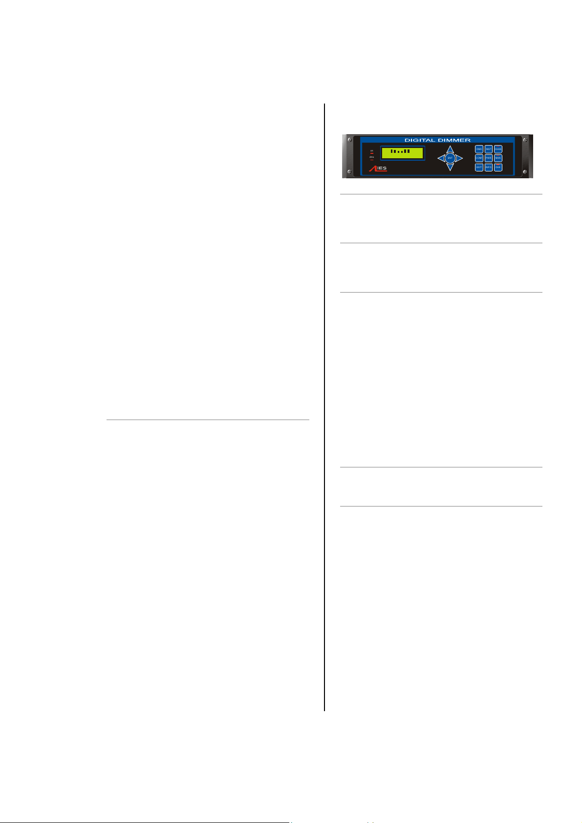
3 Control panel layout
on
L D:001*
CH 1 2 3 4 5 6 A:016*
dmx
ON LED
Illuminates red when power is applied, and the
RCBO or MCB is switched on.
DMX LED
Illuminates red continuously when valid DMX is
present. LED flashes when there is no DMX signal.
ENT & cursor arrows
ENT (ENTer) completes a programming step and
records the information in the memory
The four cursor arrows provide navigation through
the set-up menu, and the means to enter data.
Ï Up cursor. Higher level menu feature
or move cursor up in display screen or
number increment.
Ð Down cursor. Lower level menu
feature or move cursor down in display
screen or number decrement
Í Left cursor. Move cursor left in display
screen
Î Right cursor. Move cursor right in
display screen
DMX
Selects DMX address per channel.
INST
INSTall function. To set-up dimmer functionality
options as follows:
Line Voltage, frequency and current
•
DimSTAT communication address
•
DMX failure options
•
DMX backup levels
•
DMX configuration (individual or combined)
•
Channel configuration (individual or
•
combined)
Sleep mode
•
Voltage regulation
•
Current limit
•
Minimum level reset (preheat off when DMX is
•
not present)
• Voltage calibration
• Factory reset
• Channel information
• Password set-up
Dimmer hardware configuration
•
DMX INST CHAS
ENT
PWR MANCONF
INFO C HKEXIT
IES PowerModule Operators’ Manual v1.4 Isine 3
Page 4

CHAS (with LED)
CHASe. Provides access to the dimmer’s internal
20-pattern chase effects system for stand-alone
display effects. The LED illuminates when the
dimmer is in the ‘chase’ operation mode.
CONF
CONFigure. Access to a sub-menu to set the
detailed configuration for individual or combined
dimmer channels. Options available are:
MAX MAXimum. Sets the
maximum output level from
30% to 100%, individually or
combined.
MIN MINimum. Sets the minimum
output level from 0% to
29.9%, individually or
combined.
T-IN Response time to fade in from
0.00 secs to 99.9 secs.
T-OUT Response time to fade out
from 0.00 secs to 99.9 secs.
CURVE Dimmer law selection
NONDIM I/O. On/off operation
PRIORITY Priority channel (the last to be
reduced if the maximum
preset current is exceeded by
the module).
MODE Start mode (normal, soft start,
burst, proportional, blink)
4 Function overview
4.2 Maximum and minimum levels
The maximum output of the dimmer may be
adjusted to improve lamp life or to limit the power
used. A minimum level (preheat) may be necessary
with some filaments to improve the speed of fast
flashes or chases. An option exists to switch off the
preheat when the DMX signal is not present (i.e.
when the control desk is switched off).
4.3 Response speed
The time taken for a dimmer to ‘fade’ to the applied
control signal level is used to control the rate of
change of current to the filament improve lamp life
for higher wattage filaments.
4.4 Non-dim operation
Each dimmer may be selected to operate as a
dimmer, or as a non-dim switch.
4.5 Local control
PowerModules have a range of integrated control
facilities for basic operation without a control desk.
These include live manual control of each dimmer
level, preset recorded levels for fixed display
lighting, and access to an in-built chaser which
provides 20 chase patterns.
MAN
MANual. Provides manual control of each channel
for circuit testing and pre-setting.
EXIT
Returns to the opening screen menu option without
recording changes.
INFO
INFOrmation. Provides a display of the nominal
supply voltage, current and frequency. After 3 secs.
also gives details of the installed software versions.
CHK (with LED)
ChecK. Displays a log of any circuit or dimmer
faults. LED illuminates if an error occurs.
4.6 Dimmer curves
A selection of dimmer curve transfer functions (the
relationship between from control signal level and
dimmer output) are available to compensate for the
different visual responses of a live audience or a TV
camera, and to provide improved dimming for nonresistive loads such as fluorescent tubes.
4.7 Status reporting
All IES dimmers incorporate a bi-directional
communications system called DimSTAT which
provides feedback of the dimmer status and fault
reporting to a PC. DimSTAT also enables a remote
PC to control any dimmer in the network, and to
update the dimmer’s internal operating software and
preset options.
4.8 Backup settings
Should the DMX signal fail, the PowerModule can be
programmed to hold the present level, fade to zero
or fade to a pre-programmed backup level.
IES PowerModule Operators’ Manual v1.4 Isine 4
Page 5

5. Information displays and
manual control
This group of buttons provides direct access to
detailed set-up and status information and manual
override controls, and do not require passwords for
access.
5.1 To check power supply
1. Press PWR.
2. The screen shows:
U:242 V
I: 00 A
Where: U is the mains input voltage in
Volts, I is the instantaneous load
current in Amps (3 phases shown
for PM6; one for PM1, 2 and 4).
3. Press EXIT to leave the screen.
5.2 To check dimmer performance
1. Press INST.
2. Press Ð or Ï to choose CHANNEL INFO
menu. Press ENT.
3. The screen shows:
INFO CH:[1]
CURRENT 04,7A
4. Press Í or Î to select other information
as follows:
CURRENT: current in Amps measured at the
output
VOLTAGE: voltage at the input of the dimmer
TEMPERATURE: i-tech dimmer module
temperature
DMX: DMX level received
ACTUAL: the level the dimmer is responding
to (may differ from DMX value due to MIN,
MAX or MAN influence).
STATUS: error message(s) with details.
4. Press Ï or Ð to select another dimmer
channel (shown in square brackets), or,
5. Press EXIT to leave the screen.
5.3 To check dimmer software versions
1. Press INFO, and wait for 3 seconds.
2. After displaying the nominal voltage,
current and frequency settings, the screen
shows:
P1:1.44 P2:1.44
P3:1.44 SYS:3.10
Where: P1, P2 and P3 are the dimmer
processor software versions (P1 is only
shown on 1, 2 and 4 channel
PowerModules), and SYS is the front
panel processor software.
Note: All dimmer processor software will have the
same version number, but it will not be
necessarily the same version as for the
front panel. All software versions in the
same installation should be identical. If
they are not, contact your local distributor
or IES directly.
3. After 3 seconds, the screen automatically
resets to show the normal output details.
5.4 To manually control a dimmer level
It is possible to control any dimmer directly from the
front panel using the cursor controls to set the
desired level. This can be used for testing circuits,
overriding control signals or setting an independent
fixed level. The level is mixed with any other
incoming signal on a highest level takes precedence
basis.
1. Press MAN.
2. The screen shows:
L: 242V
CH:T123456 08 A
3. Use Í or Î to select a channel number
(active channel number is underlined), or
‘T’ which controls all channels together.
4. Press Ï or Ð to adjust the level. The
dimmer output is live while the level is
being adjusted.
5. Press ENT to leave the menu and record
the changes or EXIT to leave the previous
settings unchanged.
5.5 To operate the chaser
The PowerModule has a sequence chaser to
provide basic effects without a control desk. This is
primarily used for exhibition and display lighting
purposes. Twenty different effect sequences are
pre-programmed into the PowerModule, and
controls are provided to adjust master level, chase
speed and to chose between fading and switching
between steps.
1. Press CHAS.
2. The screen displays shows:
IES PowerModule Operators’ Manual v1.4 Isine 5
Page 6

CH ST SP L FADE
01 00 1,0 OFF
where:
CH is chase number
ST is step number
SP is speed (in seconds) from one step to
another
L is a bargraph showing the master intensity
FADE selects either a fading chase (ON) and
a switching chase (OFF)
3. Press Í or Î to put the underline
beneath the CH number, and use Ï and
Ð to select the chase number required.
4. Press ENT to start the chase, and the
screen shows e.g.:
CH __ AUTO
05 01 1,0 OFF
5. The step number will increment as the
chase progresses, restarting at 1 at the
end of each cycle.
6. With the chase number underlined, press
Ï or Ð to switch to another chase
pattern.
7. Use Í and Î to underline (select) the
level or FADE and press Ï or Ð to adjust
the master level for each step (shown on
the bargraph) and to choose between
FADE ON (fades between steps) and
FADE OFF (switches between steps).
For clarity, the following sections which describe
programming activities do not refer to the entry of
passwords. Passwords are included to prevent
unauthorised access to the DMX, CONFigure and
INSTall menu trees. The passwords are 4-digit
numbers with a factory default of 0000 (no password
necessary). It is possible to have the same
password for all, or separate passwords for each
menu tree. If any of the protected menus is selected,
the subsequent screen requests a password. This is
achieved by pressing the relevant Í and Î cursor
buttons to select the digit, and the Ï and Ð cursor
buttons to enter the number.
6.2.2 Navigation through the menus
The cursor buttons are used to move around the
menu screens, and to activate a set-up option or
parameter prior to adjustment. When a parameter or
option is activated, it is shown in square brackets,
e.g. [240] and it is this item which you are changing
on the screen. When you press ENT to confirm the
change, the screen will show:
DATA IS STORED
IN MEMORY
As this happens for each menu option, it is not
included in each following instruction.
6.2.3 Channel characteristics
All dimmer-specific functional parameters may be
set on a dimmer-per-dimmer basis. Thus each
dimmer may have a different response time, curve,
maximum level etc. if required. Alternatively, all
dimmers in one PowerModule can be programmed
together, depending on whether the dimmer set-up
has been set to ‘SINGLE or ‘JOINED’ (see
paragraph 6.4.1). If the configuration is set to single,
a number is shown in each relevant channel
reference [4], and if all dimmers are programmed
together, a T is shown in square brackets [T]. Note
that if T is activated, an underscore bar is added,
making it appear as an ‘I’.
6 Programming
6.1 Flow diagram
An overview of the flow chart showing the menu
structure and options is shown as an appendix at the
end of this manual.
6.2 General Programming Advice
6.2.1 Passwords
IES PowerModule Operators’ Manual v1.4 Isine 6
6.3 Front Panel Controls
All of the performance and control characteristics,
measurements and status reports, are available
from the front panel controls and LCD screen. When
power is applied and the MCB or RCBO is switched
on, the power LED will illuminate. The DMX LED will
illuminate if a valid DMX signal is present.
During the power-up reset process, the LCD display
shows identification details and the software version
before displaying the output screen:
L: _ D:001?
CH:123456 A:032v
This display shows the channel levels (bargraphs at
the top left), the DMX address of the first channel in
the PowerModule (D:xxx) and the DimSTAT address
of the unit (A:xxx). The number of bargraphs shown
Page 7

relates to the number of dimmers in the
PowerModule – either 2, 4 or 6.
Note: A questionmark (?) adjacent to the DMX
address shows the DMX signal is not
valid, and the ‘v’ adjacent to the DimSTAT
address number indicates communication
is active.
6.4 General controls
PowerModule dimmers have the capacity to store
performance characteristics individually for each
dimmer or combined for all dimmers in the module.
This feature is independent of the choice of DMX
numbering scheme, thus the dimmers may have
individual characteristics, but with consecutive DMX
addresses.
6.4.1 To change the dimmer characteristic set-up
scheme:
1. Press INST.
2. Press Ð or Ï to choose GENERAL
SETTINGS menu.
Press ENT.
3. Press Ð or Ï to choose CONFIG
CHANNEL menu.
Press ENT.
4. The screen shows:
GENERAL
CH_CONF. [SINGLE]
5. Use Ï or Ð to select either SINGLE (for
different individual channel parameters) or
JOINED (if all dimmers have the same
characteristics).
6. Press ENT (to record the changes) or
EXIT (to leave the previous settings
unchanged, and return to the home page).
6.5 DMX programming
Each dimmer in the PowerModule is assigned a
DMX channel number. A feature is provided to set
sequential number groups (‘Start’ addressing)
instead of individual settings. When programming a
PowerModule, IT IS IMPORTANT TO SET THE
DMX ADDRESSING SCHEME before the individual
characteristics are set, as a later change can reset
previously recorded individual channel characteristic
settings.
6.5.1 To set up DMX addressing scheme:
1. Press INST.
2. Press Ð or Ï to choose GENERAL
SETTINGS menu.
Press ENT.
3. Press Ð or Ï to choose DMX ADDRESS
menu.
Press ENT.
4. The screen shows:
GENERAL
DMX MODE [SINGLE]
5. Use Ï or Ð to select either SINGLE (for
different individual DMX addresses) or
JOINED (if the dimmers are numbered
sequentially from the start address).
6. Press ENT (to record the changes) or
EXIT (to leave the previous settings
unchanged, and return to the home page).
6.5.2 To set-up DMX addresses:
1. First set the DMX scheme as described
above (either individual or start address).
2. Press DMX, and the screen displays:
DMX: [001] 002
CHAN.: 1 2
3. If SINGLE has been selected, two
channels are displayed at a time, with their
relevant DMX address. Use Ï and Ð to
select the address needed for the first
dimmer channel and move to other
channels by pressing Í and Î and
continue adjusting each DMX address by
pressing Ï and Ð as before.
4. If JOINED has been selected, only one
DMX number line is entered which is the
number for dimmer 1. The remaining
dimmers are automatically addressed in
sequential order. Press ENT to store the
settings and to return to the previous
menu.
Note: DMX address 000 deselects the channel
from operation. Valid DMX numbers are
between 001 - 512. If higher dimmer
numbers are used by the control desk, the
number has to be rationalised to a base of
512 for the dimmer address.
6.5.3 To set up a DMX backup condition
The PowerModule is equipped with a choice of
responses to the failure of the DMX signal. The
dimmers can be set to hold their last DMX level,
fade to zero over 5 seconds, or fade to a preset
memory setting. This choice is available per
PowerModule.
1. Press INST.
2. Press Ð or Ï to choose GENERAL
SETTINGS menu. Press ENT.
IES PowerModule Operators’ Manual v1.4 Isine 7
Page 8

3. Press Ð or Ï to choose DMX FAIL menu.
Press ENT.
4. The screen shows:
GENERAL
DMX FAIL [HOLD]
5. Use Í or Î to select one of the 3 options
available:
RESET: sets all dimmers to zero after 5
seconds
HOLD: maintains the last valid DMX
levels until DMX is restored
BACKUP: selects dimmer levels set-up
through the PRESETS memory
facility
6. Press ENT to leave the menu and record
the changes or EXIT (to leave the
previous settings unchanged).
Note: If BACKUP has been set, do not forget to
pre-set the relevant DMX backup state.
6.5.4 To set-up DMX Backup preset:
1. Press INST.
2. Press Ð or Ï to choose DMX BACKUP
menu. Press ENT.
3. The screen shows:
L: 242V
CH:T123456 00 A
4. Use Í or Î to select a channel number
(active channel number is underlined) or T
if all channels are to be set together.
5. Press Ï or Ð to adjust the backup level.
The dimmer output is live while the backup
levels are adjusted.
6. Press ENT to leave the menu and record
the changes or EXIT (to leave the
previous settings unchanged).
6.5.5 To set-up a DMX Minimum reset
In order to reduce dynamic filament noise in some
types of 120V Par lamps, it is sometimes necessary
to use a low preheat level. DMX minimum reset is
the automatic means to switch any preheat levels off
when DMX is not present (i.e. when the control desk
is switched off, but the dimmers remain on).
1. Press INST.
2. Press Ð or Ï to choose GENERAL
SETTINGS menu.
Press ENT.
3. Press Ð or Ï to choose MIN RESET
menu. Press ENT.
4. The screen shows:
GENERAL
MIN RESET: [OFF]
5. Use Ï or Ð to select either AUTO
(preheat switches off when DMX is off) or
OFF (preheat runs continuously).
6. Press ENT to leave the menu and record
the changes or EXIT (to leave the
previous settings unchanged).
6.6 Serial address
The DimSTAT PC address which shown on the
output screen as A:XXX is the unique number which
is used by network to identify each dimmer unit for
the purpose of reporting status information and for
transferring data between the dimmer unit and PC. If
a dimmer unit is removed from the network and
replaced by another, DimSTAT will automatically
prompt for an update of configuration information
when the PC number is entered. DimSTAT identifies
the new unit on the network, and prompts the
operator to download the previous characteristics file
from the PC to the new dimmer. The PC number is
associated with a unique factory serial number
which is permanently stored in the dimmer. An
Autoreload function is also provided to reinstate the
PC address after a factory reset.
6.6.1 To set-up a serial address:
1. Press INST.
2. Press Ð or Ï to choose DIMSTAT
ADDRESS menu. Press ENT.
3. The screen shows:
ADDRESS: [001]
AUTO-RELOAD NO
4. Press Ï or Ð to set the address number
between 001 and 255.
5. Press Î to select auto-reload options of
YES or NO.
6. Press ENT to leave the menu and record
the changes or EXIT (to leave the
previous settings unchanged).
IES PowerModule Operators’ Manual v1.4 Isine 8
Page 9
6.7 Maximum & Minimum levels
6.8 Response time
It is possible to affect the output range of a dimmer
by setting a minimum level and (or) a maximum
level. A minimum level is used to provide a pre-heat
to preheat lamp filaments, whereas the maximum
level is used to limit power and extend lamp life.
Minimum levels may be set between 0% to 29.9%,
and maximum levels from 30% to 100%. Factory
default levels are 0% for minimum and 100% for
maximum. One common use for a reduced
maximum level is to control 110V lamps but the
110V dimmer curve is recommended as it produces
a smoother control over the whole range of intensity.
However this should be checked in comparison with
other lamps in the rig to ensure uniformity of
response.
Note: In the case of high-inrush loads (e.g.
Parcans) where flashing on from a cold
state is required in a silent auditorium, or
for 5kW lamps where the high inrush
current could cause the short-circuit
protection to report and error, it is
recommended to set a ‘minimum’ preheat
level to 5%. See also the section on DMX
Minimum Reset.
6.7.1 To set-up max. and min levels:
1. Press CONF.
The screen shows the individual channel
number (or T if the dimmer set-up scheme
copies characteristics to all dimmers in the
rack) and gives access to all configuration
options.
CONFIG: CH:[1]
MAX: 100%
Press Ï or Ð to select the required dimmer
number.
Press Î to select the maximum or minimum
option, and to highlight the recorded value
(in square brackets):
CONFIG: CH:1
MIN: [00,0%]
Setting options are :
MIN: minimum level from 00% to 29.9%.
MAX: maximum level from 30% to 100%.
5. Press Ï or Ð to select the level (shown in
square brackets).
6. Press ENT to leave the menu and record
the changes or EXIT (to leave the
previous settings unchanged).
Each dimmer has two times associated with it which
control the minimum time to fade in and out, and are
called T-IN and T-OUT. These times are referred to
as ‘response times’ and are used to protect the lamp
filaments from thermal damage, and for reducing
surges in the system. The default times are currently
zero seconds (for the fastest response). Values
recommended are 0.01s for a 1kW load, 0.1s for a
2kW load, and 0.5s for a 5kW load.
6.8.1 To set-up response times:
1. Press CONF.
2. The screen shows the individual channel
number (or T if the dimmer set-up scheme
copies characteristics to all dimmers in the
rack) and gives access to all configuration
options.
Press Ï and Ð to select the dimmer number.
CONFIG: CH:[1]
MAX: 100%
Press Î to select the response times T-IN or
T-OUT, and to select the recorded value
(in square brackets):
CONFIG: CH:[1]
T_OUT: [00,00]SEC
5. Adjust the time by pressing Ï and Ð.
6. Press ENT to leave the menu and record
the changes or EXIT (to leave the
previous settings unchanged).
Note: Zero (0) seconds should not be used with
TV-type high wattage lamps, where the
minimum recommended is 0.05s. Faster
response times should be used with care,
and with lower wattage loads.
IES PowerModule Operators’ Manual v1.4 Isine 9
Page 10

6.9 Dimmer curves
6.10 Non-Dim operation
Dimmer curves (dimmer laws) are used to adjust the
relationship between control level and light output.
This enables the dimmer to be fine-tuned to
accommodate the preferences of a live audience or
a television camera. There are 8 factory standard
dimmer laws, and a provision for further custom
selectable curves in later software releases.
The factory default law (0) is Linear Law. The list of
dimmer curves is as follows:
LINEAR linear relationship (standard)
LINEAR5 LIN5 (as linear but with a small
offset at 50%)
INV.LIN inverted (when control = zero,
dimmer = full etc.)
110V LIN 110V lamp load, linear law
S-LAW S-Law
BBC BBC specification (modified
square law for TV applications)
FLU-50 Fluorescent (minimum 50%)
FLU-30 Fluorescent (minimum 30%)
FLASH flash effect (light switches on and
off as the control fades up and
down)
NONDIM Non-Dim operation (see note
below)
9-14 for future use
Note: There are two options for setting Non-Dim
(switch) operation – via the CURVE menu
and the NON-DIM menu, both found in
CONF. For Non-Dim operation, either or
both options may be set, but for normal
dimmer operation BOTH must be set to
‘NO’.
6.9.1 To select a dimmer curve:
1. Press CONF.
2. The screen shows the individual channel
number (or T if the dimmer set-up scheme
copies characteristics to all dimmers in the
rack) and gives access to all configuration
options.
3. Press Ï or Ð to select the channel
number.
CONFIG: CH:[1]
CURVE: LINEAR
4. Press Î to select the CURVE option
(shown in square brackets) and set the
curve option by pressing Ï and Ð.
5. Press ENT to leave the menu and record
the changes or EXIT (to leave the
previous settings unchanged).
PowerModules may be set to switch on and off
rather than dim, and in this way are used for many
other functions such as switching power to working
lights, non-dim and auxiliary circuits. There are two
methods of selecting non-dim operation – as
described here, and also as one of the ‘Dimmer
Curves’ as described in the previous section.
Note: When in non-dim mode, the dimmer is
operating in Phase-On mode only.
6.10.1 To select a dimmer to operate as a nondim switch:
1. Press CONF.
2. The screen shows the individual channel
number (or T if the dimmer set-up scheme
copies characteristics to all dimmers in the
rack) and gives access to all configuration
options.
3. Press Ï or Ð to select the channel, and
then press Î to select the NON-DIM
option shown as follows:
CONFIG: CH:1
I/O: [NO]
4. Press Ï or Ð to select I/O operation
(either YES for Non-Dim or NO for normal
dimming operation).
5. Press ENT to leave the menu and record
the changes or EXIT (to leave the
previous settings unchanged).
Note: A special feature is included to prevent
damaging accidental ‘flashing’ to discharge
loads. If T-IN is set to, say, 10 secs. and TOUT to 99secs, then the on period is fixed for
10 seconds, and 99 seconds has to elapse
before switching on is possible again.
6.11 Maximum current
Each PowerModule has a facility to measure the
current and to restrict the operation of all dimmers
(or in the case of PM6, the dimmers on each phase)
to ensure the maximum current is not exceeded.
This operates as a ‘maximum demand’ protection
system, and reduces the levels of all dimmers on the
phase which is exceeding the preset current.
However, to eliminate the risk of an important light
automatically dimming during a performance, it is
possible to prioritise the channels which will reduce
in intensity to ensure the maximum demand is not
exceeded. This is achieved by setting the dimmer
channel to “priority”, and it will then ignore any
instruction to reduce level if the maximum demand is
exceeded.
IES PowerModule Operators’ Manual v1.4 Isine 10
Page 11
The process is in three parts; setting a current limit,
choosing any priority channels, and activating
current limiting as described below:
6.11.1 To set-up maximum current levels:
1. Press INST.
2. Press Ð or Ï to choose LINE
PARAMETERS menu. Press ENT.
3. The screen shows:
LINE V[240]
I:40 FREQ:50
4. Press Ï or Ð to set the typical voltage of
the mains supply (shown in square
brackets).
5. Press Î to select maximum current for
the module (or per phase for the PM6),
and adjust the level using Ï and Ð.
6. Press Î to select frequency and press Ï
or Ð to switch between 50Hz or 60Hz.
7. Press ENT to leave the menu and record
the changes or EXIT (to leave the
previous settings unchanged).
6.11.2 To set-up priority channels:
1. Press CONF.
2. The screen shows the individual channel
number (or T if the dimmer set-up scheme
copies characteristics to all dimmers in the
rack) and gives access to all configuration
options.
3. Press Ï or Ð to set the channel number
required, followed by Î repeatedly to
select PRIORITY option shown as follows:
CONFIG: CH: T
PRIORITY: [NO.]
4. Press Ï or Ð to select this channel for
priority operation (either YES for priority or
NO for normal operation).
Note: If set to No, the dimmer will take part in a
general lowing of intensity if the preset
maximum current (maximum demand) for
the phase in this dimmer rack is
exceeded. If set to Yes, the dimmer will
remain at its level, and others will reduce
in level to maintain a maximum phase
current.
5. Press ENT to leave the menu and record
the changes or EXIT (to leave the
previous settings unchanged).
6.11.3 To activate current limitation:
1. Press INST.
2. Press Ð or Ï to choose GENERAL
SETTINGS menu. Press ENT.
3. Press Ð or Ï to choose CURRENT LIMIT
menu. Press ENT.
4. The screen shows:
GENERAL
CUR.LIMIT: [ON]
5. Press Ï or Ð to set the current limiting
function either ON or OFF (shown in
square brackets).
6. Press ENT to leave the menu and record
the changes or EXIT (to leave the
previous settings unchanged).
6.12 Voltage regulation
Voltage regulation is a software feature which
maintains the dimmed level of channels in the event
of the mains supply fluctuating (e.g. when power is
supplied from a generator source or a highimpedance main). The dimmer’s incoming voltage is
measured, and if it diverts from the anticipated
incoming voltage, the dimmer will adjust the output
accordingly to maintain a constant voltage at the
output. The dimmer will maintain output to about 1V
for every 10V input voltage swing. This feature does
not maintain the voltage of full-on dimmer channels,
as the regulation circuit can only work with sufficient
voltage headroom. Programming involves two
stages, firstly setting the nominal voltage, and
secondly activating the voltage regulation software.
6.12.1 To set nominal voltage
1. Press INST.
2. Press Ð or Ï to choose LINE
PARAMETERS menu. Press ENT.
3. The screen shows:
LINE V[230]
I:44 FREQ:50
4. Press Ï or Ð to set the voltage expected
(shown in square brackets).
5. Press ENT to leave the menu and record
the changes or EXIT (to leave the
previous settings unchanged).
6.12.2 To activate voltage regulation
1. Press INST.
2. Press Ð or Ï to choose GENERAL
SETTINGS menu. Press ENT.
3. Press Ð or Ï to choose VOL.
REGULATION menu. Press ENT.
4. The screen shows:
GENERAL
IES PowerModule Operators’ Manual v1.4 Isine 11
Page 12

VOL.REG. [ON]
5. Press Ï or Ð to set the voltage regulation
function either ON or OFF (shown in
square brackets).
6. Press ENT to leave the menu and record
the changes or EXIT (to leave the
previous settings unchanged).
6.14 Start Mode
PowerModules are equipped with a software feature
to alter the criteria for dimming cold filaments. The
response of a dimmer depends on the resistance of
the filament, which varies according to temperature.
A cold filament has a slower response than a warm
filament. Although the Isine modules restrict
maximum current to 10 times the nominal current, if
the complete rig is subject to a sudden loss and
resumption of power (a ‘brown-out’) it is possible for
the combined cold switch-on load to be higher than
the diversified power supply can withstand, resulting
in nuisance tripping of circuit breakers. For this
reason, the dimmers are installed with a range of
start modes to give the users flexibility in the set-up
characteristics of the dimmer.
An additional feature is Blink mode which flashes the
dimmer channel with a controllable mark-space and
flash rate for warning signs in the studio or
backstage. The options are:
BASIC: Normal mode
SOFT START: If the circuit has not been used
for 5 minutes, the initial response
time is automatically set to
500mS
BURST: If the circuit has not been used
for 5 minutes, the dimmer burstfires 20 cycles at full power to
heat the filament rapidly and to
improve response.
PROP: Proportional burst start mode.
The number of full power cycles
is in relation to the speed of rise
of DMX signal between 0% and
9%.
BLINK: Flashes the output to full. T-IN
sets the fade in time, T-OUT sets
the fade out time, and the DMX
level sets the period of flash.
6.14.1 To set start mode
1. Press CONF.
2. The screen shows the individual channel
number (or T if the dimmer set-up scheme
copies characteristics to all dimmers in the
rack) and gives access to all configuration
options.
3. Press Ï or Ð to select the relevant
channel number and then repeatedly
press Î to select the START option
shown as follows:
CONFIG: CH:2
MODE: [BASIC]
4. Press Ï or Ð to select the start mode
required.
Note: If BLINK has been set, be sure to adjust the
T-IN and T-OUT times to create the
required flash characteristic, and adjust
the DMX value when used for the period
of flash.
5. Press ENT to leave the menu and record
the changes or EXIT (to leave the
previous settings unchanged).
IES PowerModule Operators’ Manual v1.4 Isine 12
Page 13
6.15 Passwords
Passwords are used at 3 levels of the PowerModule
dimmer set-up procedure: DMX, CONF. and INST.
One password or 3 separate passwords may be
used to give a range of access options. Passwords
are in the form of 4 digit codes and may be set and
used from the front panel of the dimmer and
DimSTAT, but passwords may only be read using
DimSTAT. Passwords set at 0000 give unlimited
access.
Note: If the password is set to 0000 (factory
default) the menus are open, and no
prompts to enter a password are seen on
the display. The service access password
is 3415.
2. Press Ð or Ï to choose GENERAL
SETTINGS menu. Press ENT.
Press Ð or Ï to choose SLEEP MODE
menu. Press ENT.
4. The screen shows:
GENERAL
SLEEP MODE [ON]
5. Use Ï or Ð to select either ON (dimmer
functions reduce when DMX is off) or OFF
(dimmers run continuously).
6. Press ENT to leave the menu and record
the changes or EXIT (to leave the
previous settings unchanged).
6.15.1 To set-up passwords for the first time, and
to alter a previous password:
Note: Programming passwords for DMX
programming, Channel configuration and
Installation follows the same procedure
which is described here for DMX only.
1. Press INST.
2. Press Ð or Ï to choose PASSWORD
DMX menu. Press ENT.
3. The screen shows:
NEW PASSWORD
[*]:*:*:*
4. Press Í or Î to select a digit to enter
(shown in square brackets).
5. Press Ð or Ï to adjust the digit.
Note: Make a copy of passwords set in the back
of this handbook, as the passwords can
be interrogated only via a DimSTAT link to
a remote PC. Resetting the password to
0000 disables the previous setting.
6. Press ENT to leave the menu and record
the changes or EXIT (to leave the
previous settings unchanged).
6.16 Sleep mode
The SLEEP function has been included to switch off
the backlit LCD screen during a performance when
the control panels are in view of an audience or
camera. When enabled, the sleep function switches
off the backlight a short time after the last touch of a
panel button, and switches back on when a front
panel button is pressed.
6.16.1 To set the dimmer rack to ‘Sleep’ mode
1. Press INST.
6.17 Fault reporting
If a discrepancy in the normal operating parameters
is registered, the PowerModule will report the
potential fault and will take action to minimise the
effect of the fault. The CHK LED illuminates if a fault
is recorded, and any circuit errors are reported on
the screen above the channel number affected as
shown below for channel 5 which is displaying a
short-circuit condition:
L: s D:025
CH:123456 A:001v
code ‘l’ = no load (control present but no
output)
code ‘s’ = short circuit
code ‘t ‘= over temperature
code ‘o’ = overload (e.g. 4kW plugged into a
2kW dimmer)
code ‘c’ = no control (e.g. output with no
control signal)
code ‘v’ = voltage out of range (either over
or under voltage)
code ‘d’ = fault has persisted beyond a
default auto-reset time, and the
dimmer has been disabled
awaiting manual intervention and
reset.
The channel display indicators give the last recorded
fault condition. If the fault is a self-resetting fault, or if
the dimmer is automatically disabled, the reason for
the problem may not be obvious from the channel
display. However, a log of the errors is shown in
detail through DimSTAT, and a summary of the
history is shown using the dimmer’s LCD screen as
follows:
IES PowerModule Operators’ Manual v1.4 Isine 13
Page 14

6.17.1 To check fault reports and to reset the log.
1. Press CHK.
Note: This screen never requires a password.
2. The screen shows:
ERR.STATUS: CH:01
SHORT 03
where: 03 is the short circuit error code, and
01 is the affected dimmer circuit within the
module.
3. Press Ð or Ï to view any other reports in
the error log
4. Press ENT to leave the menu and CLEAR
the log or EXIT (to leave the log
unchanged).
6.18 Return to factory settings
The PowerModule is supplied with a set of factory
default settings and recommended software set-up
parameters. It is advisable to reset the dimmer
software to the original factory settings in the case of
a significant software update.
6.18.1 To reset the dimmer rack to factory default
settings
1. Press INST.
2. Press Ð or Ï to choose FACTORY
RESET menu. Press ENT.
3. The screen shows:
ARE YOU SURE ! !
CLEAR MEM. [NO]
4. Press Ï or Ð to select YES (shown in
square brackets).
5. Press ENT to leave the menu and reset
the PowerModule’s memory or EXIT (to
leave the previous settings unchanged).
Factory defaults are:
AUTORELOAD: NO
CHANNEL CONFIG.: JOINED
CURRENT: 44A
CURRENT LIMITATION: OFF
CURVE: LINEAR
DMX ADDRESS: 001
DMX BACKUP: all 00
DMX FAIL: RESET
DMX MODE: JOINED
DMX MINIMUM RESET: OFF
FREQUENCY: 50Hz
MAXIMUM: 100%
MINIMUM: 0.00%
MODE: BASIC
NON-DIM (I/O): NO
PASSWORDS: all 0000
PC ADDRESS: 000
PRIORITY: NO
SLEEP: OFF
T-IN: 0.00 secs
T-OUT: 0.00 secs.
VOLTAGE: 235V
VOLTAGE REGULATION: OFF
.
7. DimSTAT
DimSTAT provides a system-wide network, and
operates on a host polling protocol where the PC
searches for connected dimmers at initiation, and
then regularly polls dimmers for data to display. If a
fault occurs, the PC’s display instantly shows the
detail, and if the fault is cleared the system resets
accordingly. Information displayed includes: DMX
start address per unit, DMX OK, line voltage, current
per channel, dimmer curve, response time, max.
setting, type of fault reported (temperature, overload
etc.), date and time of fault. It is possible to set the
dimmer curve, start address and pre-heat from
DimSTAT software on the PC. The operation and
performance of the PowerModule dimmer is
monitored constantly and comprehensively by the
on-board data processors, and this information is
available on the LCD screen of the dimmer, and
through DimSTAT. The parameters measured and
reported are:
a) DMX OK
b) DMX channel numbers
c) DMX levels
d) line voltage
e) current per dimmer
f) current per phase per rack
g) frequency
h) dimmer curve
i) temperature per module
j) temperature per rack
For further information, please refer to the DimSTAT
software manual.
IES PowerModule Operators’ Manual v1.4 Isine 14
Page 15

8. Fault finding
8.1 Reported faults
8.1.1 No load (control present but no output)
This can be reported if either a load fails (lamp
blows without shorting the output first), or the load is
disconnected in error, or a load is not connected.
8.1.2 Short circuit
This can happen if a lamp filament blows, or if a
faulty cable or luminaire is connected to the circuit. A
temporary short circuit such as a lamp failure will
produce a SHORT report in the log, but the dimmer
will usually reset to normal operation when the fault
has cleared. If the fault continues, the report will
change to DISABLE. Disconnect the dimmer and
check the circuit wiring and connected loads for the
short.
8.1.3 Over temperature
If one of the Isine modules exceeds an operating
temperature of 80°C, the dimmer will switch off and
report an overtemperature condition. This can be
caused if the ventilation is obstructed (e.g. the
dimmer is resting on the floor and is being used
continuously at full load).
Note: As the temperature rises above the normal
operating ceiling of 60°C, the dimmer
automatically takes progressive
temperature reducing actions such as
dynamically adjusting the filtering.
8.1.4 Overload
The dimmer will respond quickly to any error which
demands a higher current than expected, for
example 4kW plugged into a 2.5kW dimmer. The
dimmer will automatically switch off and after 3
seconds will attempt to fade up the circuit again. If
this process fails 3 times, the dimmer will report an
overload and will disable until the fault is cleared and
the dimmer reset.
8.1.5 Control
The control fault indicates a problem controlling the
load within the dimmer. This can result in the
dimmer channel giving a full output under any
control condition, and can only be repaired by an
exchange of Isine module. However, if this fault
occurs the dimmer circuit should be carefully
assessed to find a cause before another module
suffers the same problem. Typical system problems
are high voltage spikes caused by an unbalanced
generator supply.
8.1.6 Voltage out of range
If the supply voltage varies above or below the
nominal voltage anticipated (and set as the
benchmark) the dimmer will close down and report a
voltage error. In the case of temporary supply
fluctuations, the fault will auto-reset, but if the
dimmer shuts down, the first point to check is the
voltage calibration setting of the dimmer to make
sure it is set to the local supply voltage.
8.1.7 Disable
If a fault persists beyond a default auto-reset time,
the dimmer will close down awaiting manual
intervention and reset. Check the fault log to see the
type of fault which caused the dimmer to disable.
8.2 First line maintenance
This check list provides initial assistance in the case
of a problem which has not been identified and
reported by the dimmer’s own software.
8.2.1 LCD display blank
Check all power supply connections. Check
module’s RCBO or MCB is on.
8.2.2 LCD display corrupted
Switch off and on again. If the fault persists, open
the module and check all connections, and that plugin ICs are secure in their sockets.
8.2.3 No output from one channel
Check the control signal is active. Check the DMX
address is correct. Check there is no ‘l’ showing on
the output screen. Remove the itec module and
check the internal 15A fuse.
8.2.4 RCBO trips continuously
Unplug all load plugs. If the fault persists, refer to
service technician. If the RCBO holds in, replace
one plug at a time until the RCBO trips again. Check
the circuit (cables, plugs and sockets, distribution,
lights) for a loose terminals, a phase to neutral short,
a phase to earth short or a neutral to earth short and
correct where necessary.
8.2.5 Dimmer output is full on all the time
Disconnect the DMX cable to isolate control. If the
dimmer is still on, check a) the MANual level has not
been set to 100%; b) the dimmer curve has not been
set to ‘Inverted’; c) the MIN level is at zero. If the
dimmer is still on, and there is no ‘Control’ fault
identified, refer to a service technician.
If the dimmer switches off when the DMX cable is
removed, check that both NON-DIM mode
selections (dimmer curve and Channel Configuration
I/O) are set to OFF. If either or both these functions
are set ON, the dimmer will be operating in Non-Dim
mode.
IES PowerModule Operators’ Manual v1.4 Isine 15
Page 16

8.2.6 Lamp filaments are noisy
Replace the lamp with a new lamp, and in the case
of 110V Parlamps, try the circuit with a different
manufacturer’s lamp, as some lamps are noisy even
on switched mains supplies.
8.2.7 Dimmers work, but DimSTAT doesn’t
recognise all or some dimmers
Check the DMX network to ensure 2-pair cable is
used and correctly connected throughout. If a DMX
booster/isolator unit is used in the network, check
that it supports bi-directional data on pins 4 and 5.
8.2.8 Voltage regulation is not operating properly
The PowerModule uses a relative measurement of
mains voltage in the general operation of the dimmer
circuit, in the status reporting system, fault detection
and reporting, and output voltage compensation. For
accurate measurement and operation, the incoming
mains supply voltage at the dimmer is calibrated at
the factory. If this calibration is wrong, the voltagerelated parameters will be affected. The solution is
to recalibrate the PowerModule.
Note: IMPORTANT. This set-up procedure may
only be carried out by a qualified electrical
engineer as it involves an accurate
measurement of the mains supply.
8.2.9 To calibrate line voltage
This requires a true RMS digital voltmeter, and a
safe means of connecting the voltmeter to the
dimmer’s supply. If the mains supply is known to
have a high impedance, it is advisable to take the
measurement under normal operating loads so that
voltage drop in the supply can be accommodated in
the measurement.
1. Measure the voltage of the PowerModule
power supply.
2. Press INST.
3. Press Ð or Ï to choose CALL.VOLTAGE
menu. Press ENT.
4. The screen shows:
SERV CODE ????
ENTER ↵ ÅÇÈÆ
4. Press Ï to set the first number to ‘3’ and
press Î to enter the other digits ‘4’, ‘1’,
‘5’. The screen now shows:
L-1 L-2 L-3
[242] --- ---
Note: The screen shows L-1, L-2 and L-3 for the
three-phase PM6 PowerModule.
5. Press Ð and Ï to adjust the voltage to
match the voltage measured at the supply.
Continue with the other two phases in the
case of the PM6.
6. Press ENT to leave the menu and record
the changes or EXIT (to leave the
previous settings unchanged).
IES PowerModule Operators’ Manual v1.4 Isine 16
Page 17

10. Declaration of conformity
DECLARATION OF CONFORMITY
According to ISO / IEC Guide 22
Manufacturer’s name: I.E.S. B.V.
3903 LA Veenendaal
Netherlands
Declares that the product:
Product name: PowerModule
Model number: PowerModule no.2234 / 2101 / 2102 / 2235 /
2103 / 2104 / 2236 / 2237 /
2105 / 2106 / 9820.
Conforms to the following product Specifications:
Emission EN 50081-1 / EN 50081-2
EN 55011
EN 55014
Immunity EN 50082-1 / EN 50082-2
EN 55024-2 6 kV Contact discharge
8 kV Air discharge
EN 55024-3 3 V / m
EN 55024-4 1 kV Signal lines
2 kV Power lines
Supplementary information: The product complies with the EMC Directive
89/336/EEC.
Veenendaal
December 2000
J.H.D. de Jonge
Technical Manager
Manufacturer’s address:
I.E.S. B.V.
Wageningselaan 52-54
IES PowerModule Operators’ Manual v1.3 17
Page 18

11. Index
Backup settings
defined................................................................5
BASIC
mode defined ....................................................12
BLINK
mode defined ....................................................12
BURST
mode defined ....................................................12
calibrate line voltage
how to ...............................................................16
Channel characteristics ...........................................6
CHAS
front panel control ...............................................4
chaser operation
how to .................................................................6
CHECK
illuminated sign .................................................13
CHK
front panel control ...............................................4
CONF ......................................................................4
Connections.........................................................1, 2
Control
error message...................................................15
Control panel layout.............................................1, 3
current limitation
enable & disable ...............................................11
data
view channel data ...............................................5
data signals .............................................................3
Declaration of conformity.......................................20
dimmer
data.....................................................................5
dimmer characteristic set-up scheme
to change ............................................................7
dimmer curve
setup .................................................................10
Dimmer curves.....................................................1, 9
defined............................................................1, 4
dimmer level
chaser control .....................................................6
manual control ....................................................5
DimSTAT ...............................................................14
fault finding .......................................................16
disabled
error message.............................................13, 15
Distributed dimming.............................................1, 2
DMX
front panel control button ....................................3
DMX address
setup ...................................................................7
DMX addressing scheme:........................................7
DMX backup condition
setup ...................................................................8
DMX backup preset
setup ...................................................................8
DMX booster/isolator ...............................................3
DMX data signals.....................................................3
DMX LED.................................................................3
DMX Minimum reset
setup ...................................................................8
DMX network........................................................... 3
DMX programming .............................................. 1, 7
DMX termination ..................................................... 3
ENT & cursor arrows............................................... 3
errors reported
codes................................................................ 13
EXIT
front panel control............................................... 4
Factory defaults
defined..............................................................14
factory settings...................................................... 14
Fault finding....................................................... 1, 15
Fault reporting................................................... 1, 13
faults
history report .................................................... 14
filaments are noisy
fault finding....................................................... 16
First line maintenance....................................... 1, 15
forward and reverse phase operation
setup................................................................. 12
Forward or reverse phase operation ................... 1, 4
Front Panel Controls ........................................... 1, 6
Function overview ............................................... 1, 4
General controls.................................................. 1, 7
IGBT dimming technology....................................... 2
INFO
front panel control............................................... 4
Information displays ............................................ 1, 5
INST
front panel control button.................................... 3
installation ........................................................... 1, 2
Introduction ......................................................... 1, 2
itec technology
IGBT dimming .................................................... 2
Key features of itec system ................................. 1, 2
LCD display
fault finding....................................................... 15
live data
view channel data............................................... 5
Local control
defined............................................................1, 4
location.................................................................... 2
MAN
front panel control............................................... 4
manual control..................................................... 1, 5
manually control a dimmer level
how to................................................................. 5
max. and min levels:
setup................................................................... 9
Maximum
levels - defined ............................................... 1, 4
Maximum & Minimum levels................................ 1, 9
Maximum current .............................................. 1, 10
maximum current levels
setup................................................................. 11
MCB
fault finding....................................................... 15
minimum
levels - defined ............................................... 1, 4
Minimum reset
IES PowerModule Operators’ Manual v1.3 18
Page 19

DMX control ........................................................8
Navigation through the menus.................................6
no control
error message.............................................13, 15
no load
error message.............................................13, 15
Non-dim operation .............................................1, 10
defined............................................................1, 4
non-dim switch
setup .................................................................10
ON LED ...................................................................3
output
fault finding .......................................................15
Over temperature
error message...................................................15
overload.................................................................13
error message...................................................15
Passwords .....................................................1, 6, 13
setup .................................................................13
Phase-On and Phase-Off ..................................1, 12
Pin connections .......................................................3
Positioning...........................................................1, 2
Power connections ..............................................2, 3
power supply
checking..............................................................5
priority channels
setup .................................................................11
Product range ......................................................1, 2
Programming .......................................................1, 6
Programming Advice ...........................................1, 6
PROPortional
mode defined ....................................................12
RCBO
fault finding .......................................................15
RCD
fault finding....................................................... 15
Reset
factory defaults................................................. 14
Response speed
defined............................................................1, 4
Response time .................................................... 1, 9
response times
setup................................................................... 9
reverse phase operation...................................... 1, 4
Safety.................................................................. 1, 3
Serial address ..................................................... 1, 8
setup................................................................... 8
short circuit
error message ............................................ 13, 15
Sleep mode ....................................................... 1, 13
setup................................................................. 13
SOFT START
mode defined.................................................... 12
software
checking installed versions................................. 5
Specifications.................................................... 1, 17
standards .............................................................. 18
Start Mode......................................................... 1, 12
setup................................................................. 12
Status reporting
defined............................................................1, 5
temperature
error message ............................................ 13, 15
Unpacking ........................................................... 1, 2
voltage
error message ............................................ 13, 15
Voltage regulation ............................................. 1, 11
setup................................................................. 11
XLR
pin connections .................................................. 3
IES PowerModule Operators’ Manual v1.3 19
Page 20
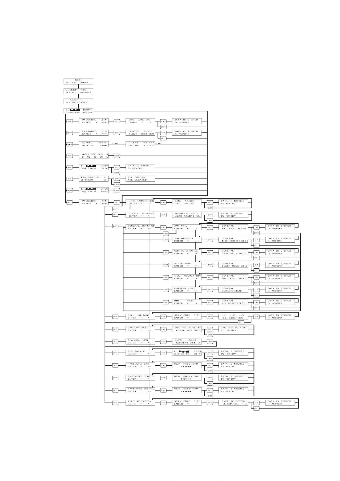
Appendix: Flowchart.
IES PowerModule Operators’ Manual v1.3 20
Page 21

IES PowerModule Operators’ Manual v1.3 21
 Loading...