

Page 1
Portable Pack
USER MANUAL
Contents
Introduction .......................................................................3
SP6 face panel components ............................................ 3
SP12 face panel components .......................................... 4
Electronics modules ..........................................................5
Removing .................................................................... 5
Dimmer modules ..............................................................6
Circuit breakers............................................................6
LEDs ............................................................................ 6
Removing .................................................................... 6
Line and load connectors .................................................. 7
SP6 single phase operation...............................................8
SP12 single phase operation ............................................ 9
Input connectors ............................................................. 10
Connector pinout data ...............................................10
Beacon ............................................................................ 11
Door .... ...........................................................................11
Cooling system ...............................................................12
Specifications ..................................................................12
Electronic Theatre Controls, Inc.
UL and C UL Listed
AC Lighting Loads Only
For Indoor Use Only
Utilizer Dans Un Endroit A L'Abri
ETC Sensor dimming equipment is protected by
US patent number 5,352,958.
7052M1002
3030 Laura Lane, Middleton, WI 53562
800/688-4116 FAX 608/836-1736
Copyright 1994-95 Electronic Theatre Controls, Inc.
Specifications subject to change. Revised 7-95.
Page 2

2 Electronic Theatre Controls, Inc.
Page 3
Introduction
The Sensor Portable Pack is a modular dimming system that
consists of a single electronics module and multiple dimmer
modules in a fan-cooled, aluminum and steel housing. It is
available in standard and Advanced Features (AF) configurations.
❶
Beacon
❸
Analog
0 - 10 VDC
❷
OutIn
AMX192
Address
In DMX512
Thru
Off On
Termination
Switch
Error
Phase A
IAS
Phase B
Phase C
Analog
AMX
DMX
Off On
Termination
Switch
Reset
❹
Sensor Portable Pack User Manual 3
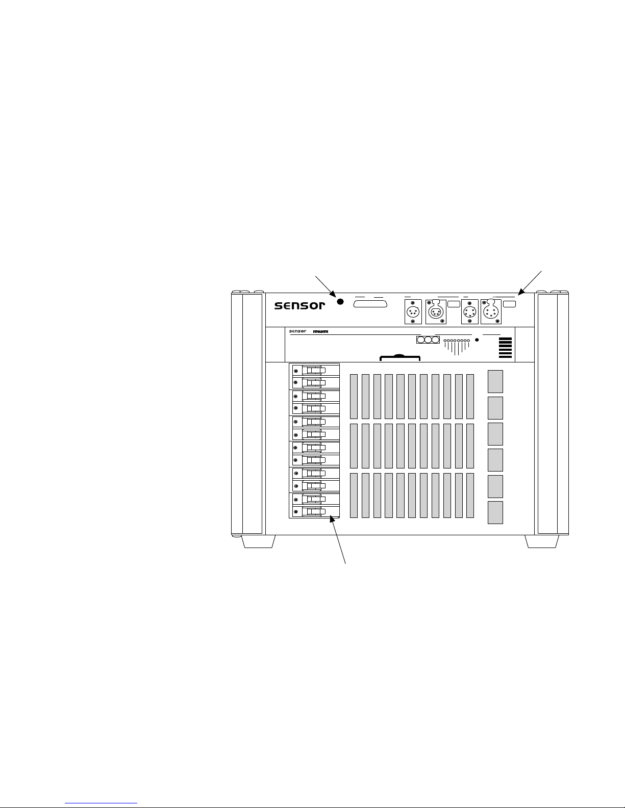
SP6 Portable Pack
❺
❶ LED beacon
❷ Input connector panel
❸ Electronics module (MPE shown)
❹ Door
➎ Circuit breakers
Page 4
❶
❷
Beacon
Analog
0 - 10 VDC
OutIn
AMX192
Off On
Termination
In DMX512
Thru
Off On
Termination
Switch
Switch
❸
Address
Phase A
Phase B
Reset
Error
IAS
Phase C
Analog
AMX
DMX
❹
4 Electronic Theatre Controls, Inc.
❺
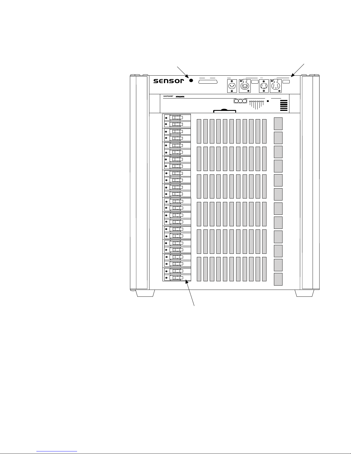
❶ LED beacon
❷ Input connector panel
❸ Electronics module
❹ Door
➎ Circuit breakers
SP12 Portable Pack
Page 5
Electronics modules
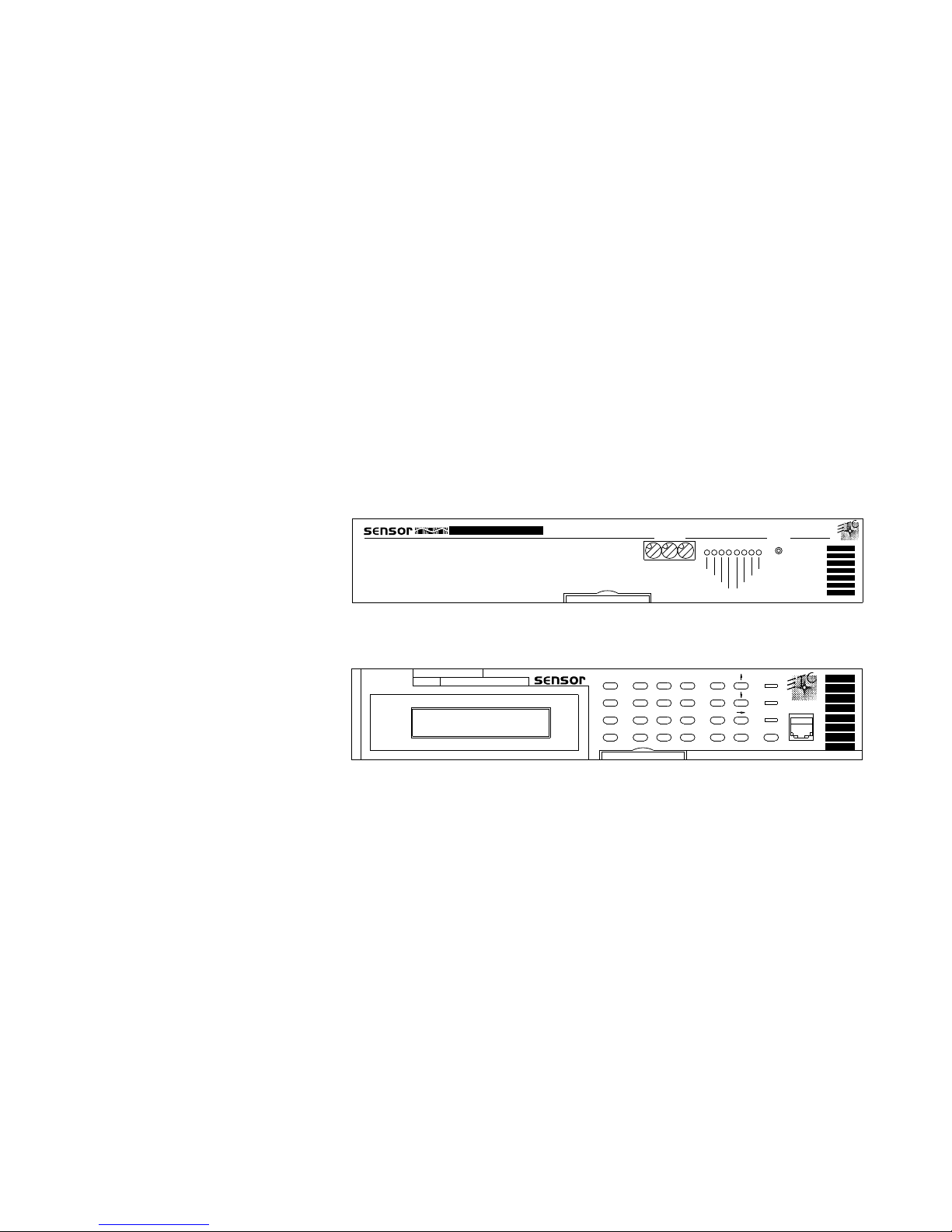
Standard configuration Sensor Portable Packs are generally
equipped with a Multi-Protocol Electronics (MPE) module.
MPE modules are factory-configured for seven user-selectable
dimmer configurations and accept DMX512, AMX192 and 0 –
10V DC analog input. Advanced Features (AF) packs are
equipped with a Control Electronics Module (CEM). CEMs
accept only DMX512, but feature an easy-to-use user interface that incorporates an integral LCD and keypad.
Like all Sensor dimming systems, the Portable Pack provides
feedback on dimming system status. In packs equipped with
the MPE, this is accomplished via a warning beacon and a
system of flashing LEDs. AF packs also provide a warning
beacon, but the CEM also provides extensive error messages
and warnings on the integral LCD. In addition, AF packs may
be networked on ETCLink, and provide feedback information
on individual dimmer modules.
For more information regarding the electronics module, see
the
CEM User Manual
with your system.
or
MPE User Manual
that was shipped
111
Multi-Protocol Electronics (MPE) Module
Dimmer
7
8
About
4
5
Backup
Setup1A/B
2
0
Control Electronics Module (CEM)
Removing electronics modules
To remove the electronics module, follow these steps:
1. Open the door.
2. Pull the small metal handle out of the bottom edge of the
front panel.
3. Grasp the handle and gently pull the electronics module
out.
Phase A
Phase B
9
6
3
At
Phase C
DMX
Exit
Next
Thru
Clear
Error
IAS
Analog
AMX
Enter Reset
ResetAddress
OA
OB
ETCLink
OC
Sensor Portable Pack User Manual 5
To replace the module, insert it firmly until you feel it seat
securely. When the module is correctly seated, it should be
flush with the dimmers. Be sure to slide the handle back into
the front panel.
Page 6
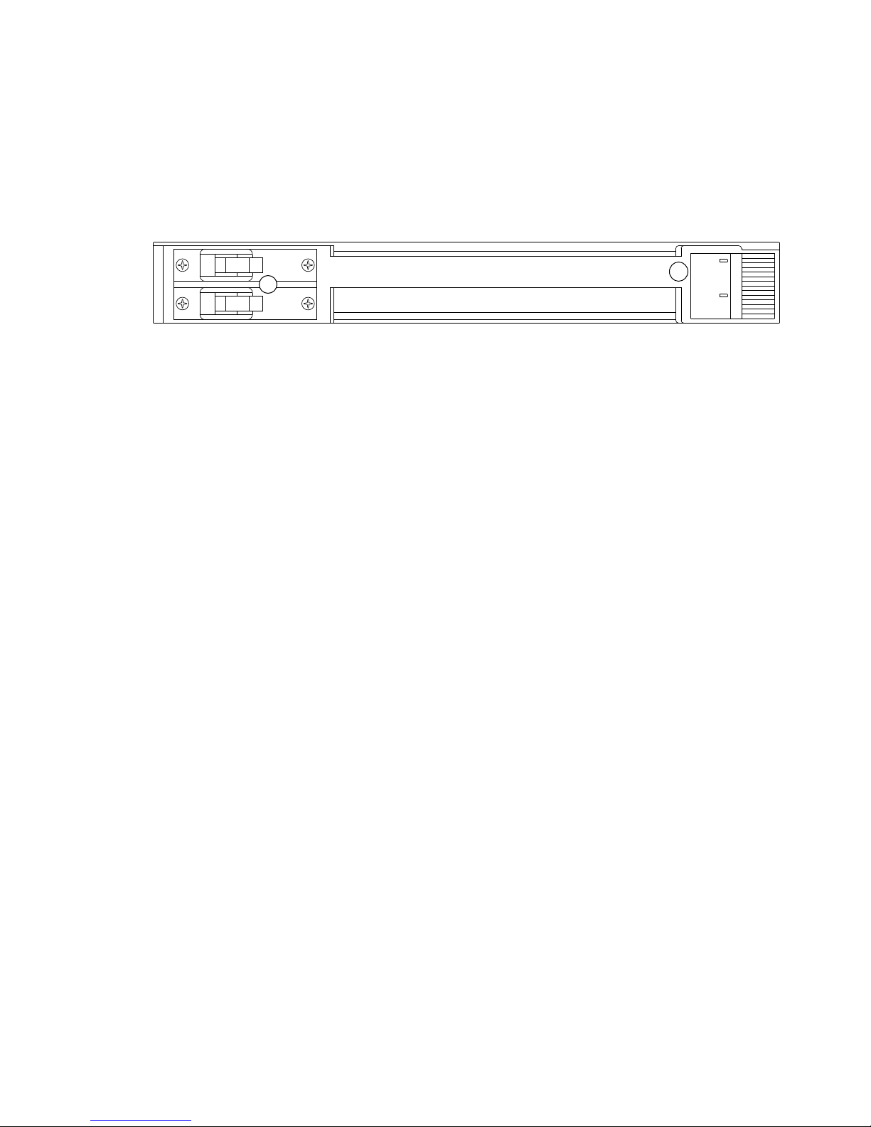
Dimmer modules
Each SP6 contains one electronics module and either six
standard or three double-height dimmer modules. Each SP12
contains one electronics module and either twelve standard or
six double-height dimmer modules. Sensor packs support
15A, 20A, 50A, or 100A dimmer modules in various combinations. (Custom dimmer configurations are available by special
order.)
20
OFF
20
❶
OFF
Standard Sensor 20A dimmer module (D20)
Except for 15A and 20A modules, which are interchangeable,
module slots are designed to accept only the size module
specified for that space. Do not attempt to insert a module
into a slot configured for a different size module.
❶
Dimmer module circuit breakers
On the left end of a dimmer module’s front panel are either
one or two circuit breakers (depending on whether the
module is single or dual). If the breaker switch is to the right,
the circuit is off or tripped. If the breaker switch is to the left,
the circuit is on.
❷
Signal
20 A
Signal
20 A
❷
LEDs
All modules have an LED marked Signal on the right end of
the front panel. The Signal LED is on whenever the pack is
receiving DMX512 input.
Sensor AF (Advanced Features) dimmer modules also have an
LED marked Output which is on whenever the dimmer has
an output voltage. Dual modules have two sets of LEDs.
Removing dimmer modules
To remove dimmer modules, open the door, then grasp the
center part of the face panel with both hands and pull.
To replace the module, insert it firmly until you feel it seat
securely. When the module is correctly seated, it should be
flush with the other dimmer modules.
Warning: Do not touch the AC power bus. If more than one
adjacent modules are removed, the AC bus is exposed.
6 Electronic Theatre Controls, Inc.
Page 7

Line and load connectors
The back panel of the Sensor Portable Pack contains both line
and load connectors.
Load connectors
The Sensor Portable Pack may be configured with either stage
pin; grounded twistlock; parallel blade; or multi-pin connectors
(Veam, Socapex or Pyle) to connect the pack to lights or other
output devices.
Line feed connectors
The back panel contains Cam-Lok® E1016 series line feed
connectors. Line feed cables with mating connectors (not
supplied) must be connected to the Cam-Lok power connectors in the order described below. To connect the Cam-Lok
connector, insert it into the back of the pack, then twist
clockwise until it locks in place. Reverse this procedure to
disconnect the cables.
Connect cables in this order:
1. Grounding plug (Green)
2. Neutral plug (White)
3. Phase plugs (Black/Red/Blue)
Warning: Cables must be disconnected in the reverse
sequence!
Warning: Multiple power leads may be attached to the
Portable Pack. Disconnect all power leads before servicing or
attempting to work on any part of this device. Service connectors must be installed and removed by qualified personnel
only.
Sensor Portable Pack User Manual 7
Page 8
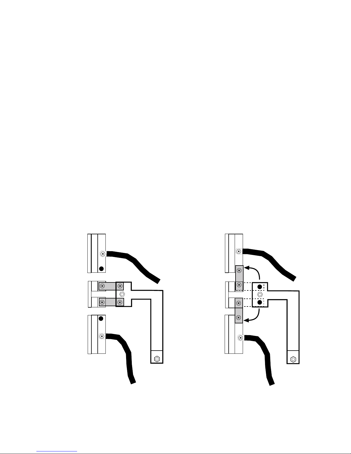
Setting up SP6 for single phase
operation
To convert a Sensor SP6 Portable Pack from three phase to
single phase operation, follow these steps:
1. Disconnect power from all Cam-Loks.
2. Remove all dimmer modules from the Portable Pack,
exposing the bus bars and connectors.
3. Remove the screws at the right ends of the two inch long
copper bars that connect the phase B connector to the
phase B bus bar. Loosen the screws at the left end of the
bars.
4. Rotate the top bar up and secure it to the phase A
connector.
5. Rotate the bottom bar down and secure it to the phase C
connector.
6. Tighten all screws to 40 inch/pounds of torque.
7. Replace dimmer modules.
8. Connect power to the A and C phase Cam-Loks. Do not
connect power to the B phase Cam-Lok.
Phase A
connector
Phase B
connector
Phase C
connector
Single phase operation is automatically detected by both
the CEM and the MPE, so no additional configuration is
necessary.
Phase A
connector
Phase B
connector
Phase C
connector
Phase connectors wired
for three phase operation
8 Electronic Theatre Controls, Inc.
Phase connectors wired
for single phase operation
Page 9
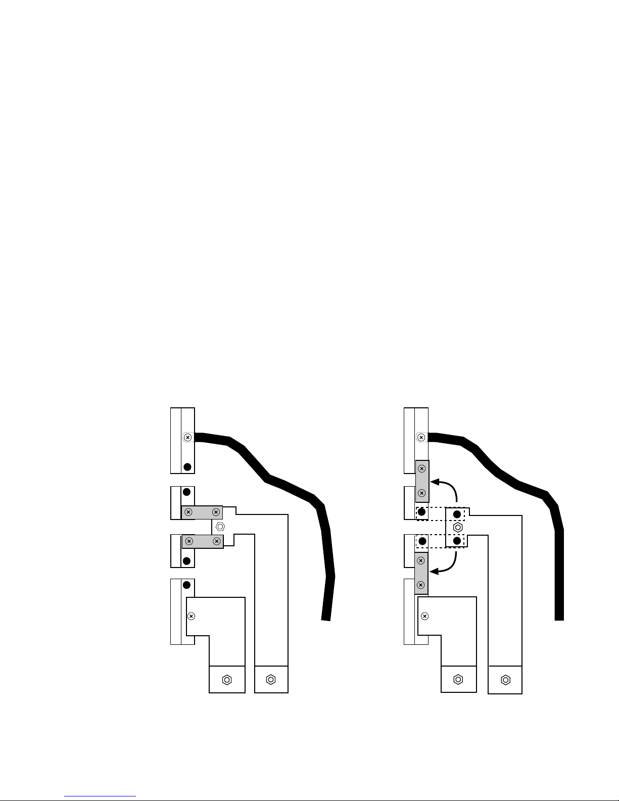
Setting up SP12 for single phase
operation
To convert a Sensor SP12 Portable Pack from three phase to
single phase operation, follow these steps:
1. Disconnect power from all Cam-Loks.
2. Remove all dimmer modules from the Portable Pack,
exposing the bus bars and connectors.
3. Remove the screws at both ends of the two inch long
copper bars that connect the phase B connector to the
phase B bus bar. Loosen the screws at the left end of the
bars.
4. Use the top bar to connect the phase A connector to the
phase B connector, as shown below.
5. Use the bottom bar to connect the phase B connector to
the phase C connector, as shown below.
6. Tighten all screws to 40 inch/pounds of torque.
7. Replace dimmer modules.
8. Connect power to the A and C phase Cam-Loks. Do not
connect power to the B phase Cam-Lok.
Phase A
connector
Phase B
connector
Phase C
connector
Single phase operation is automatically detected by both
the CEM and the MPE, so no additional configuration is
necessary.
Phase A
connector
Phase B
connector
Phase C
connector
Phase connectors wired
for three phase operation
Sensor Portable Pack User Manual 9
Phase connectors wired
for single phase operation
Page 10
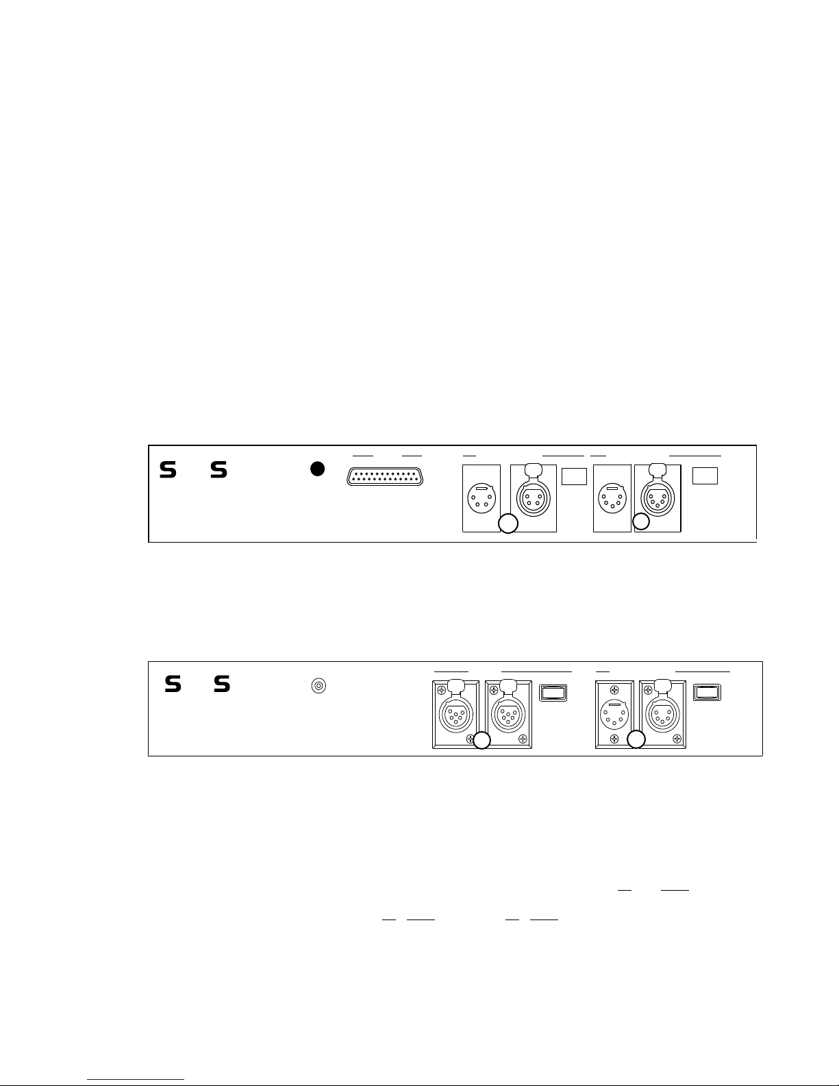
Input connectors
Input connector panel (MPE)
Beacon
The Sensor Portable Pack is available with two input connector panel options. Standard configuration packs are equipped
with input and pass-through connectors for DMX512 and
AMX192, as well as a single analog input. Advanced Features
packs are equipped with DMX512 and ETCLink input and
pass-through connectors. On an SP12, each analog channel
controls two dimmers. Analog channel 1 controls dimmers 1
and 13, channel 2 controls dimmers 2 and 14, and so forth.
Note: Sensor electronics modules are somewhat interchangeable. The CEM will work in a standard pack, but it will not
accept AMX192 or analog input. On the other hand, an MPE
will work in an AF pack, but it will not support Sensor’s
Advanced Features (AF) option.
DMX512 and AMX192 termination switches are located next
to their respective connectors. The termination switch on the
last pack in the series must be in the ON position. Termination
switches on all other packs must be in their OFF positions.
Analog
0 - 10 Vdc
AMX192
OutIn
PUSH
Off On
Termination
Switch
DMX512
In
Thru
PUSH
Off On
Termination
Switch
❶
❷
❸
❶ 0 - 10 Vdc analog input
❷ AMX192 input and pass-through
❸ DMX512 input and pass-through
Input connector panel (CEM)
Beacon
❶ ETCLink input and pass-through
❷ DMX512 input and pass-through
Note: You may use DMX512 and AMX192 inputs simultaneously or DMX512 and analog inputs simultaneously, but you
may not use AMX192 and analog inputs simultaneously.
ETCLink
PUSH PUSH
❶
OnOff
Termination
Switch
In
DMX512
❷
Thru
PUSH
OnOff
Termination
Switch
Connector pinout information
DMX512 in AMX192 in
XLR 5-pin male XLR 4-pin female
DMX512 thru AMX192 thru
XLR 5-pin female XLR 4-pin male
Pin Signal Pin Signal
1 ..... Common 1 ..... Common
2 ..... Data (-) 2 ..... Clock (+)
3 ..... Data (+) 3 ..... Analog multiplex
4 ..... Pass through 4 ..... Clock (-)
5 ..... Pass through
Analog In
D-sub 25-pin female
Pin Signal
1-12 .......Signal
13-24 .....Not used
25 .......... Common
10 Electronic Theatre Controls, Inc.
Page 11

Beacon
An LED status beacon is mounted in the top left corner of the
pack’s front panel. Under normal operating conditions, this
beacon is illuminated. If the pack’s electronics module senses
an error condition in the pack, the beacon flashes until the
error is corrected.
In packs with the MPE, the beacon alerts you to run the MPE
diagnostic routines to determine what the problem is. See the
MPE User Manual
In packs with the CEM, the beacon alerts you to check the
CEM’s LCD for error messages. See the
for more information.
Door
Each Sensor Portable Pack is equipped with a door that
protects the dimmer modules and contains the cooling
system’s electrostatic air filter. To ensure proper cooling,
always keep the door closed except when you are working on
the pack.
for more information.
CEM User Manual
Sensor Portable Pack User Manual 11
Page 12

Cooling system
The Sensor Portable Pack is cooled by a fan located on the
back panel. The pack’s cooling fan draws air through the filter,
over the surfaces of the modules and then blows it out the
back of the pack. The fan runs when any of the dimmers in
the pack are on. They continue to run for three minutes after
all dimmers are off.
Warning: Never obstruct the fan exhaust by placing objects
that may block air flow behind your pack.
For optimum performance, the average ambient temperature
in an area where a Sensor Portable Pack is being used should
be about 68°F (20°C). Under no circumstances should the
ambient temperature be allowed to exceed 104°F (40°C).
Air filter
A door-mounted, electrostatic air filter removes dust and other
airborne debris from the cooling air. This filter must be kept
clean to ensure proper cooling. The filter should be cleaned
every six months (more often in dirty locations). Follow these
steps to clean the filter:
1. Open the door.
2. Brush or vacuum filter from both sides.
3. If a more thorough cleaning is necessary, use compressed
air to blow out embedded dust and dirt.
4. Close the door.
To remove air filter (for replacement or more thorough cleaning) follow these steps.
1. Open the door.
2. Use a Phillips-head screwdriver to remove the metal strip
holding down the left side of the filter.
3. Remove filter from door.
4. Reverse procedure to replace filter.
Specifications
SP6
15 “H x 17“W x 12“D
Empty weight: 40 pounds
Input power
80A, 120/208, 3Ø, 5-wire, 50/60HZ
120A, 120/240, 1Ø, 4-wire, 50/60HZ
10,000 Amps RMS @ 120/240 VAC
SP12
24“H x 17“W x 12“D
Empty weight: 68 pounds
Input power
160A, 120/208, 3Ø, 5-wire, 50/60HZ
240A, 120/240, 1Ø, 4-wire, 50/60HZ
10,000 Amps RMS @ 120/240 VAC
12 Electronic Theatre Controls, Inc.
 Loading...