

ETC DRd12-24-240, DRd6-12-240, DRd12-24-230, DRd12-24-277, DRd12-48-120 Installation Manual
...Page 1
Copyright © 2013 Electronic Theatre Controls, Inc.
All Rights reserved.
Product information and specifications subject to change.
Part Number:
7183M2100
Rev C
Released: December 2013
DRd Rack Enclosure
Installation Manual
Revision C
Page 2

ETC®, Unison Paradigm® and SmartLink® are either registered trademarks or trademarks of Electronic Theatre
Controls, Inc. in the United States and other countries.
Echelon
®
, LON®, and LonWorks® are registered trademarks of the Echelon Corporation in the United States and
other countries. All other trademarks, both marked and not marked, are the property of their respective owners.
ETC intends this document, whether printed or electronic, to be provided in its entirety.
Page 3

Table of Contents i
Table of Contents
Introduction . . . . . . . . . . . . . . . . . . . . . . . . . . 1
Warnings and Notice Conventions . . . . . . . . . . . . . . . . . . . . . . .2
Contacting ETC . . . . . . . . . . . . . . . . . . . . . . . . . . . . . . . . . . . . . .2
DRd Rack Components . . . . . . . . . . . . . . . . . . . . . . . . . . . . . . . . . . .3
Prepare for Installation . . . . . . . . . . . . . . . . . 5
Unpack and Inspect . . . . . . . . . . . . . . . . . . . . . . . . . . . . . . . . . . .5
Main Circuit Breaker Protection . . . . . . . . . . . . . . . . . . . . . . . . . .5
Using 90° Copper Wire . . . . . . . . . . . . . . . . . . . . . . . . . . . . . . . .5
Maximum Current Draw of Racks . . . . . . . . . . . . . . . . . . . . . . . .6
Short Circuit Current Rating (SCCR) . . . . . . . . . . . . . . . . . . .6
Where to Install the Rack Enclosure . . . . . . . . . . . . . . . . . . . . . . . . .7
Clearance Requirements . . . . . . . . . . . . . . . . . . . . . . . . . . . . . . .7
Rack Dimensions and Weights . . . . . . . . . . . . . . . . . . . . . . . . . .7
Installation Environment Requirements . . . . . . . . . . . . . . . . . . . .8
Wire Routing and Specification . . . . . . . . . . . . . . . . . . . . . . . . . .8
Control Specifications . . . . . . . . . . . . . . . . . . . . . . . . . . . . . . . . .9
Control Wire Specification . . . . . . . . . . . . . . . . . . . . . . . . . .10
Data Types and Topologies . . . . . . . . . . . . . . . . . . . . . . . . . .10
Install Rack Enclosures. . . . . . . . . . . . . . . . 12
Mounting Individual DRd Rack Enclosures . . . . . . . . . . . . . . . . . . .13
Mounting Individual Racks on a Wall. . . . . . . . . . . . . . . . . . . . .13
Mounting a DRd Rack Enclosure on a Pedestal . . . . . . . . . . . . . . .14
Mounting Auxiliary and DRd Rack Enclosures Together . . . . . . . . .15
Rough-in Conduit and Wiring . . . . . . . . . . . 17
Prepare the DRd Rack . . . . . . . . . . . . . . . . . . . . . . . . . . . . . . . . . . .18
Remove the DRd Rack Power Supply/Dimming Engine Access
Panel . . . . . . . . . . . . . . . . . . . . . . . . . . . . . . . . . . . . . . . . . . . . .18
Modify Phase Bus for 120 VAC Split Phase Operation . . . . . . .19
Rough-in Conduit to the DRd Rack . . . . . . . . . . . . . . . . . . . . . . . . .21
Procedure . . . . . . . . . . . . . . . . . . . . . . . . . . . . . . . . . . . . . . . . .23
Terminate Wiring. . . . . . . . . . . . . . . . . . . . . 24
Connect Line Power Wiring . . . . . . . . . . . . . . . . . . . . . . . . . . . . . . .25
Connect Line Feed in an Individual DRd Rack Installation . . . .25
100, 120, 127 VAC, 3Ø DRd Racks . . . . . . . . . . . . . . . . . . .26
230 VAC Neutral Disconnect DRd Rack. . . . . . . . . . . . . . . .27
240, 277 VAC DRd Racks . . . . . . . . . . . . . . . . . . . . . . . . . .27
Connect Load Wires. . . . . . . . . . . . . . . . . . . . . . . . . . . . . . . . . . . . .28
Fluorescent Load Wiring . . . . . . . . . . . . . . . . . . . . . . . . . . . . . . . . .30
Page 4

ii Unison® DRd Rack Enclosure Installation Manual
3-wire Fluorescent . . . . . . . . . . . . . . . . . . . . . . . . . . . . . . . . . . .30
2-wire Fluorescent . . . . . . . . . . . . . . . . . . . . . . . . . . . . . . . . . . .31
Connect Control Wiring . . . . . . . . . . . . . . . . . . . . . . . . . . . . . . . . . .32
Overview . . . . . . . . . . . . . . . . . . . . . . . . . . . . . . . . . . . . . . . . . .32
DRd Right I/O Data Terminations . . . . . . . . . . . . . . . . . . . . . . .33
Auxiliary Power . . . . . . . . . . . . . . . . . . . . . . . . . . . . . . . . . . .33
SmartLink™ / LinkPower (LON) Control Wiring . . . . . . . . . .34
UL 924 Listed Panic Input. . . . . . . . . . . . . . . . . . . . . . . . . . .35
DMX Control Wiring . . . . . . . . . . . . . . . . . . . . . . . . . . . . . . .35
DMX Input Wire Termination using the Screw Terminals Con-
nector . . . . . . . . . . . . . . . . . . . . . . . . . . . . . . . . . . . . . . . . . . .35
DMX Input Wire Termination using the Insulation Displacement
Connector (IDC) . . . . . . . . . . . . . . . . . . . . . . . . . . . . . . . . . . .36
AX12X Cross-bussed Rack Interconnection. . . . . . . . . . . . .36
Terminate the Unison Options (URTO and UBPO) . . . . . . .36
Terminate DMX. . . . . . . . . . . . . . . . . . . . . . . . . . . . . . . . . . .37
DRd Left I/O Data Termination . . . . . . . . . . . . . . . . . . . . . . . . .38
Connect to Serial RS-232 . . . . . . . . . . . . . . . . . . . . . . . . . . .38
Connect to Ethernet RJ-45 . . . . . . . . . . . . . . . . . . . . . . . . . .38
Connect to Contact Inputs and Contact Outputs . . . . . . . . .39
Terminate Contact Inputs . . . . . . . . . . . . . . . . . . . . . . . . . . . .39
Terminate Contact Outputs . . . . . . . . . . . . . . . . . . . . . . . . . . .39
Install Rack Options . . . . . . . . . . . . . . . . . . 40
Install Rack Options . . . . . . . . . . . . . . . . . . . . . . . . . . . . . . . . . . . . .41
DALI Option Kit . . . . . . . . . . . . . . . . . . . . . . . . . . . . . . . . . . . . .41
Install the DALI Option Kit. . . . . . . . . . . . . . . . . . . . . . . . . . .41
Connect DALI Option Wiring. . . . . . . . . . . . . . . . . . . . . . . . .43
Fluorescent Option Kit . . . . . . . . . . . . . . . . . . . . . . . . . . . . . . . .44
Connect Fluorescent Option Wiring . . . . . . . . . . . . . . . . . . .45
Ride Thru Option Kit . . . . . . . . . . . . . . . . . . . . . . . . . . . . . . . . .46
Install the Ride Thru Option Kit. . . . . . . . . . . . . . . . . . . . . . .46
Connect Ride Thru Option Wiring . . . . . . . . . . . . . . . . . . . . .47
Battery Pack Option Kit . . . . . . . . . . . . . . . . . . . . . . . . . . . . . . .47
Install the Battery Pack Option Kit . . . . . . . . . . . . . . . . . . . .47
Final Installation and Power Up . . . . . . . . . 50
Checking the Rack Installation before Installing Modules . . . . . . . .51
Sealing Rack Air Leaks . . . . . . . . . . . . . . . . . . . . . . . . . . . . . . .52
Final Installation. . . . . . . . . . . . . . . . . . . . . . . . . . . . . . . . . . . . .53
Control Bypass (Test Mode) . . . . . . . . . . . . . . . . . . . . . . . . . . .54
Engage Module Retention Bar. . . . . . . . . . . . . . . . . . . . . . . . . .55
Modules Specification. . . . . . . . . . . . . . . . . 56
CE 230V Emergency Modules . . . . . . . . . . 58
About Emergency Modules . . . . . . . . . . . . . . . . . . . . . . . . . . . .58
Wire Termination . . . . . . . . . . . . . . . . . . . . . . . . . . . . . . . . . . . .58
Non Neutral Disconnect Racks . . . . . . . . . . . . . . . . . . . . . . .59
Neutral Disconnect Racks . . . . . . . . . . . . . . . . . . . . . . . . . .59
Page 5
Introduction 1
Introduction
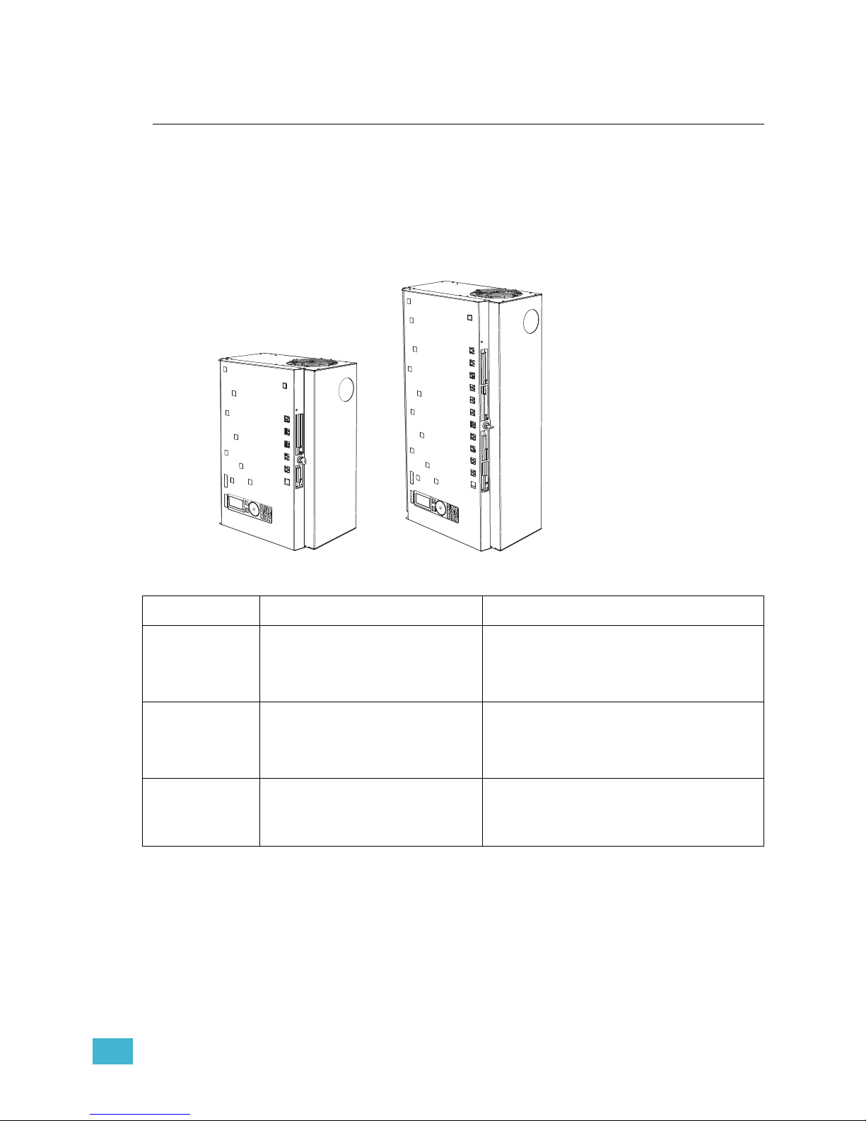
Welcome to the installation manual for Unison® DRd rack enclosures. This manual contains
the procedures for safe and efficient installation of your DRd rack enclosure and related
rack terminations.
Use this manual in conjunction with the Unison Auxiliary Rack Enclosure Installation
Manual when your DRd rack is to be installed with an adjoining auxiliary rack enclosure.
DRd Series Rack Enclosures
Series Voltage Notes
DRd6-12-120
DRd6-12-240
DRd6-12-230
DRd6-12-277
120/208 VAC
240/415 VAC
230/400 VAC CE Neutral Disconnect
277/480 VAC
6 module rack enclosure for up to 12 circuits.
DRd12-24-120
DRd12-24-240
DRd12-24-230
DRd12-24-277
120/208 VAC
240/415 VAC
230/400 VAC CE Neutral Disconnect
277/480 VAC
12 module rack enclosure for up to 24 circuits.
DRd12-48-120
DRd12-48-240
DRd12-48-277
120/208 VAC
240/415 VAC
277/480 VAC
Two 12 module rack enclosures for up to 48
circuits. DRd12-48 racks are cross-bussed using
the AX12X series main lug or main breaker
enclosure.
DRd6 rack
DRd12 rack
Page 6
2 Unison® DRd Rack Enclosure Installation Manual
Warnings and Notice Conventions
These symbols are used throughout this installation manual to alert you to danger or
important information:
Contacting ETC
For questions about Unison system delivery, contact ETC Systems Group. For general
information, your most convenient resources are the references provided in this manual. To
search more widely try the ETC web site at www.etcconnect.com.
For technical questions about Unison systems, contact ETC Technical Services directly at
one of the offices listed below. Emergency service is available from all ETC offices outside
of normal business hours. When calling for assistance, please have the following
information handy:
• Your location and job name.
• A complete list of ETC equipment.
• A complete list of other installed products and components connected to the system
you are troubleshooting.
• DMX control source, if any.
Please email comments about this manual to: [email protected]
Note:
Notes are helpful hints or information that is supplemental to the main text.
CAUTION:
A Caution statement indicates situations where there may be undefined or
unwanted consequences of an action, potential for data loss, or an equipment
problem.
WARNING:
A Warning statement indicates situations where damage may occur, people
may be harmed, or there are serious or dangerous consequences of an
action.
WARNING:
RISK OF ELECTRIC SHOCK! This warning statement indicates situations
where there is a risk of death by electric shock.
Americas
ETC International
Technical Services Department
3031 Pleasant View Road
Middleton, WI 53562
800-775-4382 (USA, toll-free)
+1-608 831-4116
[email protected]
United Kingdom
Electronic Theatre Controls, Ltd.
Technical Services Department
26 - 28 Victoria Industrial Estate
Victoria Road,
London W3 6UU, UK
+44 (0)20 8896 1000
[email protected]
Asia
ETC Asia, Ltd.
Technical Services Department
Room 1801, 18/F, Tower 1, Phase 1
Enterprise Square
9 Sheung Yuet Road
Kowloon Bay, Kowloon, Hong Kong
+852 2799 1220
[email protected]
Germany
Electronic Theatre Controls, GmbH
Technical Services Department
Ohmstrasse 3
93607, Holzkirchen, Germany
+49 (80 24) 47 00-0
[email protected]
Page 7
Introduction 3
DRd Rack Components
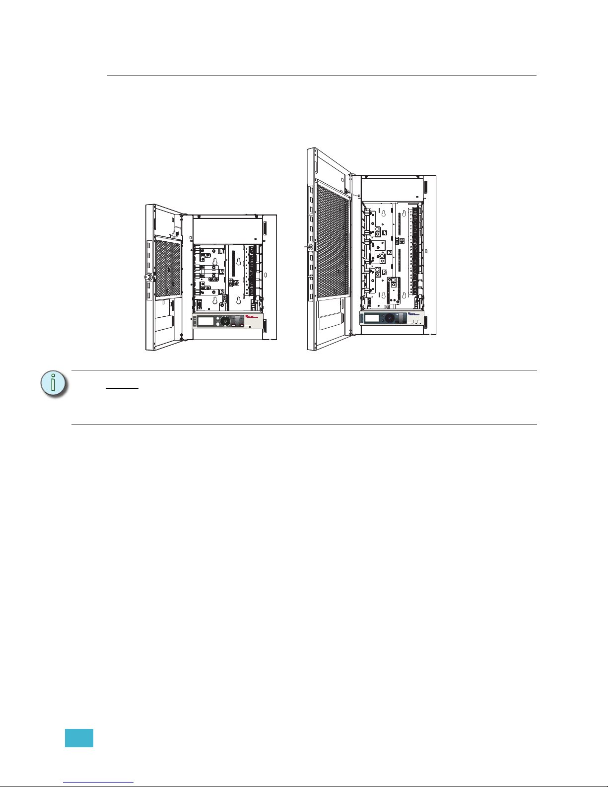
Unison DRd racks are available in 6 or 12 module enclosures and are available for an input
voltage range of 85-300 VAC, 47-63 Hz. Racks are pre-wired and supplied with three
phase, 4 wire and ground, main lugs which are easily converted for split phase, 3 wire and
ground, operation without the need for additional materials.
DRd racks are available in 12, 24 and 48 circuit configurations.
DRd rack enclosures are supplied pre-wired for the specified voltage for your installation.
All rack enclosures operate at specified voltages within a frequency range of 47-63 Hz.
Phases within the rack enclosure may be bused together provided the maximum supplied
current does not exceed that of a three phase connection.
• 100 / 200 VAC, 47-63 Hz, 1Ø
• 100 / 173 VAC, 47-63 Hz, 3Ø
• 120 / 208 VAC, 47-63 Hz, 3Ø
• 120 / 240 VAC, 47-63 Hz, 1Ø
• 127 / 220 VAC, 47-63 Hz, 3Ø
• 230 / 400 VAC, 47-63 Hz, 3Ø CE with Neutral Disconnect
• 240 / 415 VAC, 47-63 Hz, 3Ø
• 277 / 480 VAC, 47-63 Hz, 3Ø
• Supports universal dimmer modules, fluorescent dimmer modules, constant circuit
breaker modules, relay modules, and reverse phase dimmer modules. Reference
“Modules Specification” , page 56 for a complete list of compatible modules.
• The DRd rack is controlled from either the SmartLink
®
Architectural Control Processor
(S-ACP) or the Paradigm™ Architectural Control Processor (P-ACP).
Note:
In 48-circuit configurations, two DRd12-24 rack enclosures are cross-bussed to an
AX12X series main lug or main circuit breaker auxiliary rack enclosure. A single
Architectural Control Processor (SmartLink ACP or Paradigm ACP) provides
control for both racks.
DRd6
DRd12
Page 8

4 Unison® DRd Rack Enclosure Installation Manual
• The use of a station power module provides power nd control for architectural control
stations.
• Use a SmartLink station power module (S-SPM) in a DRd rack enclosure to provide
power for up to 16 SmartLink architectural control stations when used with the
SmartLink ACP.
• Use a Paradigm station power module (P-SPM) in a DRd rack enclosure to provide
power for up to 32 Unison architectural control stations when used with the
Paradigm ACP.
• The fluorescent option board (DRd-FLO) provides up to 24 outputs for control of 4-wire
(0-10 Vdc) fluorescent ballasts (up to 12 on a DRd6).
• The digital addressable lighting interface (DALI) option kit (DRd-DALI) controls 24
loops of 64 DALI compatible fluorescent ballasts in a broadcast mode.
• The Unison battery pack option kit (UBPO) provides power back-up to the Architectural
Control Processor in the rack for a period up to 90 minutes.
• The Unison ride through option kit (URTO) provides power to the Architectural Control
Processor in the rack for a limited time (up to 10 seconds) during brief power outages
or drop outs.
• All empty module spaces in a DRd rack enclosure must be filled with airflow module
(AFM) or blank modules (DRd-BM) for proper rack cooling.
• The DRd pedestal (DRd-PED) is a floor mounting stand for the DRd rack enclosure.
Page 9

1 Prepare for Installation 5
Chapter 1
Prepare for Installation
Unpack and Inspect
Before you begin installation, check your shipment and confirm it arrived complete and
undamaged.
Step 1: Check the shipping container for physical damage.
Step 2: If you find damage, document it to help with a claim against your shipper.
Step 3: Unpack your order and check the contents against the packing list to be sure
your order is complete.
Step 4: If you discover a problem, call the ETC Systems Group the closest office of
purchase. See “Contacting ETC” on page 2.
Main Circuit Breaker Protection
Before you begin installing the Unison® rack enclosure, make sure you have installed a
main circuit breaker cabinet or other readily accessible input power disconnect device. In
certain bussed and cross-bussed systems, this disconnect device may be the Unison AX
series auxiliary rack with a main circuit breaker.
Using 90° Copper Wire
To comply with UL requirements:
Use Copper Conductors Only, the torque rating for each Non-Class 2 field-wire
connector, and “Use 90°C conductors at the 75°C Ampacities”, where readily visible in
the field wiring compartment; Class 2 adjacent to each Class 2, field-wiring connector.
Use only 90°C-rated copper wiring installed in accordance with all applicable local electrical
codes.
WARNING:
Rack enclosures installed without an accessible power disconnect device
cannot be serviced or operated safely. Follow all local codes and
restrictions.
Before removing dimmer or control modules for service, de-energize main
feed to dimmer rack and follow appropriate Lockout/Tagout procedures as
described in NFPA Standard 70E. It is important to note that electrical
equipment such as dimmer racks can present an arc flash safety hazard if
improperly serviced. This is due to available large short circuit currents on
the feeders of the equipment. Any work on energized equipment must
comply with OSHA Electrical Safe Working Practices.
CAUTION:
A two-wire circuit with separate hot and neutral conductors is required for every
branch circuit that will be connected to the DRd rack enclosure. Shared neutral
(multi-wire) branch circuit arrangements are not recommended for phase control
dimming systems due to harmonics and potentially elevated neutral currents in a
shared neutral arrangement.
For retrofit installations where shared neutral circuits are already installed, or track
lighting installations where the track has a shared neutral, consult ETC Technical
Services for installation guidelines.
Page 10
6 Unison® DRd Rack Enclosure Installation Manual
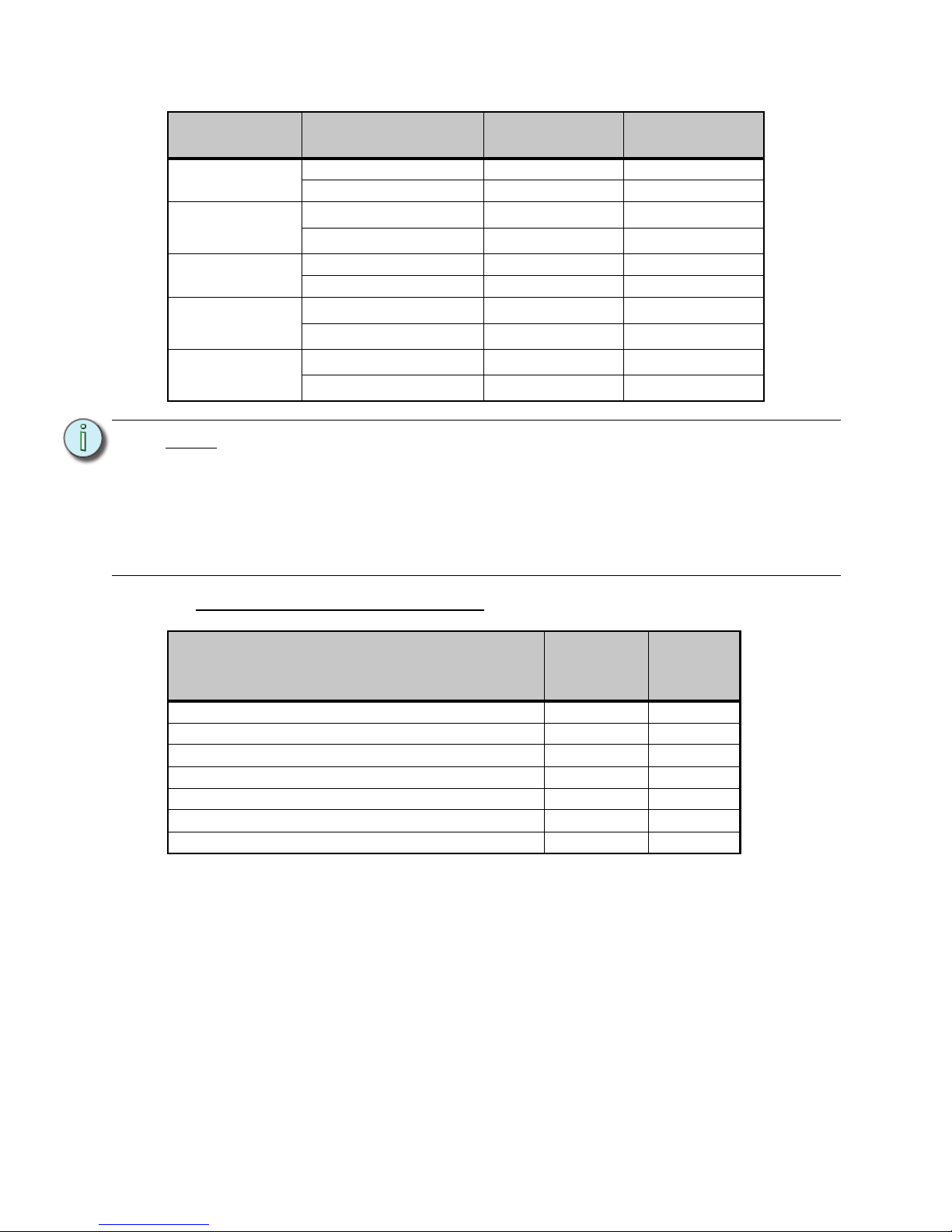
Maximum Current Draw of Racks
Short Circuit Current Rating (SCCR)
Rack Type Phase Type
Maximum
Current Draw
Suggested
Breaker Rating
DRd6
Single Phase (1Ø) 120A 150A
Three Phase (3Ø) 80A 100A
AX6
Single Phase (1Ø)
120A
1
150A
3
Three Phase (3Ø)
80A
1
100A
3
DRd12
Single Phase (1Ø) 240A 300A
Three Phase (3Ø) 160A 200A
AX12
Single Phase (1Ø)
240A
1
300A
3
Three Phase (3Ø)
160A
1
200A
3
AX12X
Single Phase (1Ø)
480A
2
400A
4
Three Phase (3Ø)
320A
2
400A
3
Note:
1
Connected to DRd rack enclosure with a full complement of 20A modules.
2
Connected to two DRd rack enclosures with a full complement of 20A modules.
3
Installed in a main circuit breaker (MCB) model auxiliary rack.
4
Wire bending space limits the feed to the AX12X-MCB rack to 400A maximum.
ETC installs a 100% rated two pole breaker (or two poles from a three pole
breaker) in the AX12X-MCB, for a total deliverable current of 400A in a single
phase (split phase) configuration.
Rack Configuration
SCCR at
100-120
VAC
SCCR at
240 & 277
VAC
DRd6 22,000A 22,000A
DRd6 with AX6 rack (MCB) 100,000A 65,000A
DRd12 22,000A 22,000A
DRd12 with AX12 Main Lug rack 22,000A 22,000A
DRd12 with AX12X (cross-bussed) Main Lug rack 22,000A 22,000A
DRd12 with AX12 Main Circuit breaker 100,000A 65,000A
DRd12 with AX12X Main Circuit breaker 100,000A 65,000A
Page 11
1 Prepare for Installation 7
Where to Install the Rack Enclosure
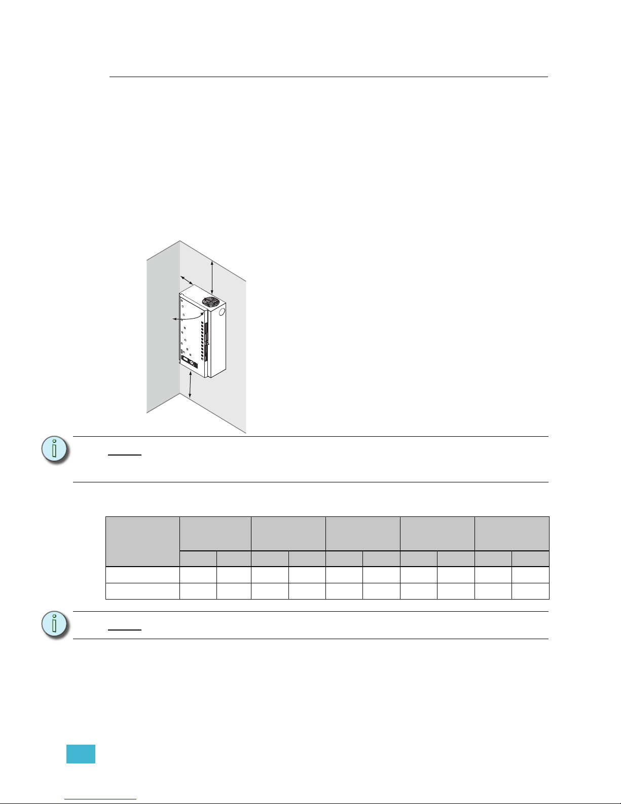
Unison DRd rack enclosures are designed to be surface mounted on load bearing walls in
an electrical closet or a room with restricted public access. It is recommended that you
install the rack at least 36” (915mm) off the floor surface to ensure clear view of the
Architectural Control Processor (S-ACP or P-ACP) for programming and operation.
Alternatively, DRd racks may install to a floor standing pedestal (model DRd-Ped).
Clearance Requirements
Unison dimmer racks require 12” (305mm) top clearance for proper airflow through the
cabinet. For sufficient door clearance, install the rack with at least 17” (432mm) of front
clearance and a 6” (152mm) clearance to the left of the door hinge from walls or other
equipment.
Rack Dimensions and Weights
Note:
Additional Unison® dimming and auxiliary racks of the same size are the exception
to the 6” (152mm) hinge side clearance rule. Unison racks are designed for side
by side use without issue.
Rack Type
Height Width Depth
Product
Weight
Shipping
Weight
inches mm inches mm inches mm lbs kgs lbs kgs
DRd6 rack
21.8 553 17 431 10 254 37.8 17.2 42 19.0
DRd12 rack
31 787 17 431 10 254 51 23.1 55 25
Note:
For module weight please reference Modules Specification, page 56.
305 mm
(12”)
152 mm
(6”)
432 mm
(17”)
914.4 mm
(36”)
Page 12
8 Unison® DRd Rack Enclosure Installation Manual
Installation Environment Requirements
• For your own safety, install a main circuit breaker cabinet or other readily accessible
input power disconnect device in the same area as the Unison DRd rack enclosure. For
cross-bussed rack installations, this device may be the auxiliary rack. Main breakers
not in the same room must have a physical means to be locked off. ETC recommends
adopting lockout / tagout procedures for your facility and follow appropriate Lockout/
Tagout procedures as described in NFPA Standard 70E.
• A clean (not dusty) temperature-controlled environment with an ambient temperature
of 32-104°F / 0-40°C and ambient humidity of 10-90%, non-condensing.
• Restricted public access to prevent tampering.
• Soundproofing or performance area separation to muffle ventilation fan noise is
recommended.
• All CE equipment is tested to EMC category B environment.
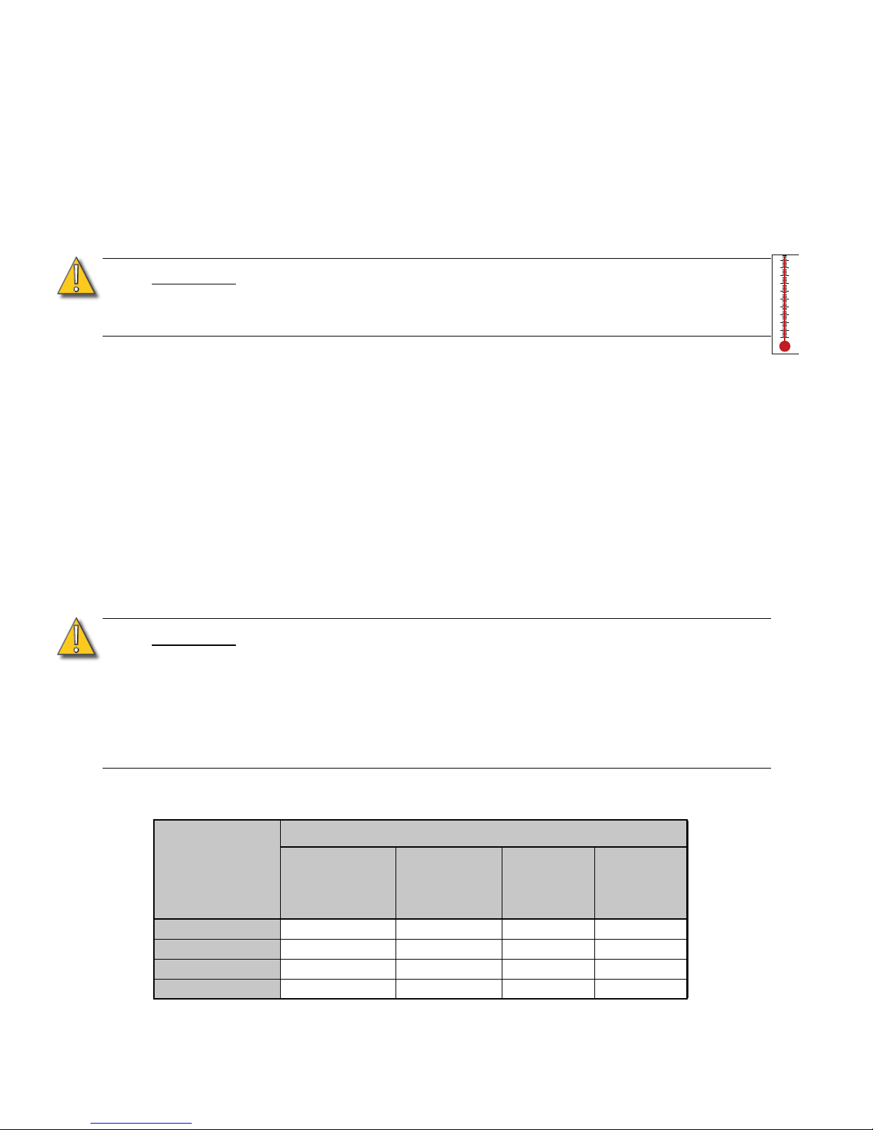
Wire Routing and Specification
When planning wire entry into the rack, notice that conduit knockouts are provided only on
the sides of the unit. These knockouts are primarily used for bussing to an auxiliary rack but
may also be used for load or control wiring. Signal and power wiring must be run in separate
conduit per local code.
Due to the bend radii of certain size line feed wires and the location of terminations, special
attention is required for line feed wire entry. Reference the rack wiring guidelines below for
recommendations.
CAUTION:
HVAC systems must at all times maintain the specified ambient temperature at the
rack. Dimming systems operating within 10°F (5°C) of the upper or lower
temperature limits must strictly follow installation and operation guidelines to
operate reliably.
CAUTION:
Do not route line (input feed) wires through the back panel. Doing so requires bend
radii that violate NEC code, UL standards and because of undue stress at the wire
joint is likely to create a poor connection.
Line and load wire used with Unison rack enclosures must be copper. Load wires
may either be stranded (preferred) or solid core. The use of aluminum wire is not
allowed in DRd rack enclosures.
Aluminum feed wires are supported only in the auxiliary (AX Series) rack
enclosures.
100-127 VAC DRd Rack Enclosure
Wire Access
Location
Wire Size
DRd12 Feed
(max)
350 Kcmil
185mm
2
DRd6 Feed
(max)
2/0-3
70mm
2
Load Wires
12 - 6AWG
2.5 - 16mm
2
Control Wires
Top of rack
acceptable acceptable acceptable acceptable
Bottom of rack
acceptable acceptable acceptable preferred
Left side
Do Not Use Do Not Use acceptable acceptable
Right side
Do Not Use Do Not Use acceptable acceptable
0°
10°
20°
30°
40°
50°
60°
70°
80°
90°
100°
-18°
-10°
0°
10°
20°
30°
40°
Page 13
1 Prepare for Installation 9
Control Specifications
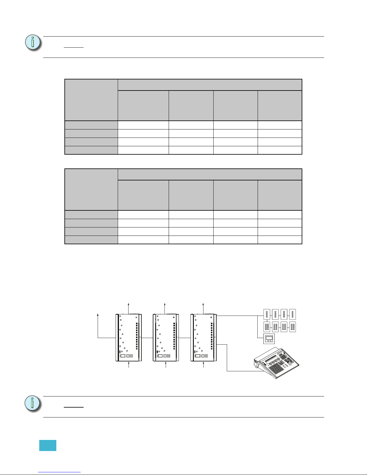
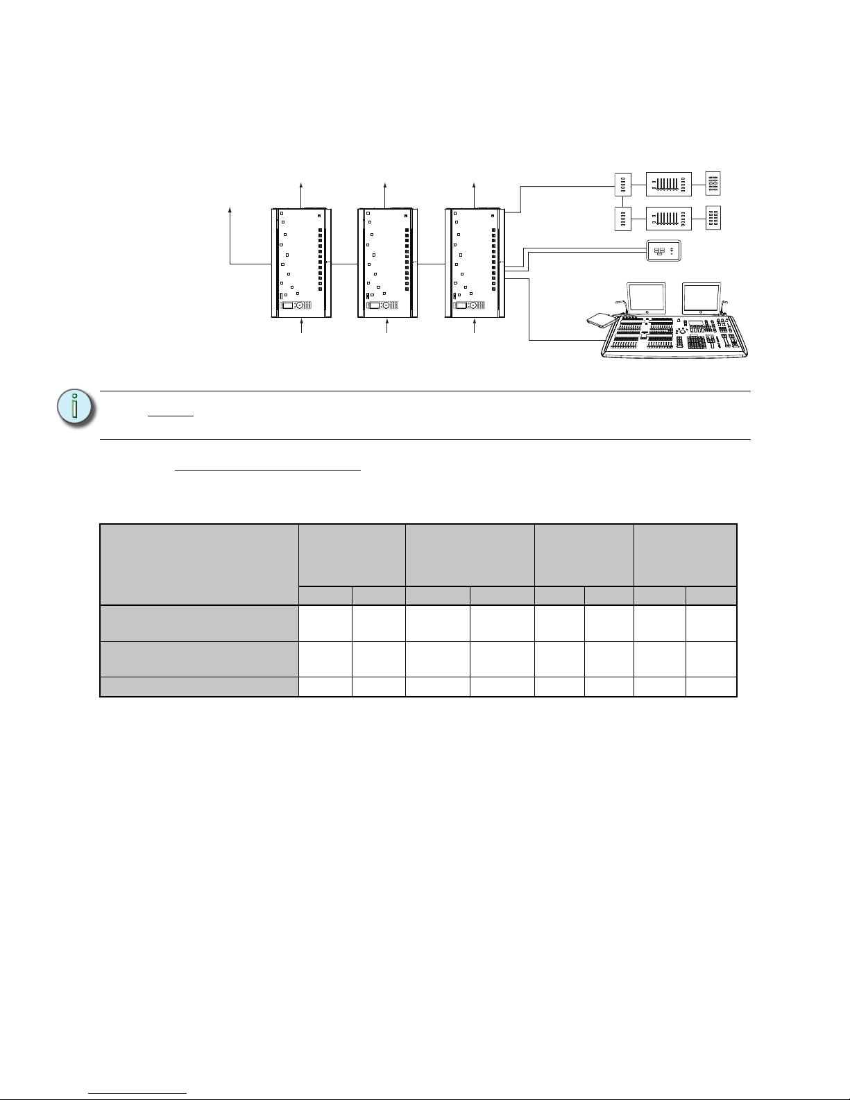
The riser below is typical of a small Unison system utilizing SmartLink Architectural Control
Processors (S-ACP) for control and SmartLink architectural control stations for preset recall
and sequence activation. A DMX input into the DRd racks provide an additional level of
system control and integrates the architectural and theatrical lighting control systems.
Note:
Split phase applications require a simple field adjustment to the phase bussing.
See “Modify Phase Bus for 120 VAC Split Phase Operation” on page 19.
230 VAC DRd Rack Enclosure
Wire Access
Location
Wire Size
Feed (max)
350 Kcmil
185mm
2
DRd6 Feed
(max)
250 KCmil
120mm
2
Load Wires
12 - 6AWG
2.5 - 16mm
2
Control Wires
Top of rack
acceptable acceptable acceptable acceptable
Bottom of rack
acceptable acceptable acceptable preferred
Left side
Do Not Use Do Not Use acceptable acceptable
Right side
Do Not Use Do Not Use acceptable acceptable
240, 277 VAC DRd Rack Enclosure
Wire Access
Location
Wire Size
DRd12 Feed
(max) 250 Kcmil
120mm
2
DRd6 Feed
(max)
2/0-3
70mm
2
Load Wires
12 - 6AWG
2.5 - 16mm
2
Control Wires
Top of rack
acceptable acceptable acceptable acceptable
Bottom of rack
acceptable acceptable acceptable preferred
Left side
Do Not Use Do Not Use acceptable acceptable
Right side
Do Not Use Do Not Use acceptable acceptable
Note:
DRd rack enclosures are shipped with the lugs installed in a top feed orientation
by default. You may change the lug orientation to a bottom feed as needed.
To a ddi t i ona l
DRd rack
enclosures
SmartLink
& DMX
power
feed
power
feed
power
feed
To load circuits
LinkPower
DMX input
to DRd rack
ETC Console
(for optional stage lighting)
SmartLink
Preset 10
Preset 6
Preset 7
Preset 9
Preset 8
Preset 5
Preset 1
Preset 2
Preset 4
Preset 3
Preset 10
Preset 6
Preset 7
Preset 9
Preset 8
Preset 5
Preset 1
Preset 2
Preset 4
Preset 3
Preset 10
Preset 6
Preset 7
Preset 9
Preset 8
Preset 5
Preset 1
Preset 2
Preset 4
Preset 3
Preset 10
Preset 6
Preset 7
Preset 9
Preset 8
Preset 5
Preset 1
Preset 2
Preset 4
Preset 3
Preset 5
Preset 1
Preset 2
Preset 4
Preset 3
Preset 5
Preset 1
Preset 2
Preset 4
Preset 3
Preset 5
Preset 1
Preset 2
Preset 4
Preset 3
Preset 5
Preset 1
Preset 2
Preset 4
Preset 3
Unison DRd12
rack enclosure
Unison DRd12
rack enclosure
Unison DRd12
rack enclosure
SmartLink stations
SmartLink
Astronomical
Timeclock
Congo jr
console
Back
Up
Enter
Recall
Preset
Hold
Down
Page 14
10 Unison® DRd Rack Enclosure Installation Manual
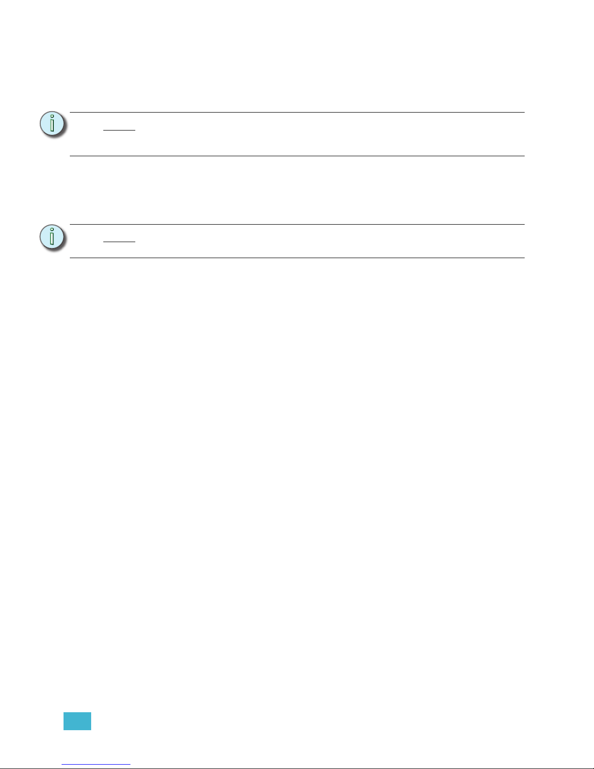
The riser below is typical of a Unison system utilizing Paradigm Architectural Control
Processors (P-ACP) for control and Unison architectural control stations for user controls.
Paradigm systems provide a DMX input into the system for larger system integration and
control. A Paradigm system also utilizes Net3 networking for an additional level of system
wide control.
Control Wire Specification
The following table lists the recommended control wire types used in Unison DRd rack
installations and the maximum length (aggregate) of wire runs allowed.
Data Types and Topologies
LinkConnect with LinkPower
LinkConnect is the station communication bus from the Architectural Control Processor to
the stations. LinkConnect is based on Echelon
®
LonWorks™ with LinkPower bidirectional
protocol, and uses one pair of wires (data +, data -). You should pull an additional 14 AWG
(1.5mm
2
)wire for grounding when not installed in grounded metal conduit.
ETC uses two types of LinkConnect networks, for SmartLink and Paradigm systems. While
the wiring for LinkConnect in SmartLink and Paradigm systems are the same, the two
communication and control types are not interchangeable. SmartLink products are
compatible only with the SmartLink ACP, SmartLink station power module, and SmartLink
architectural control stations. Paradigm products are compatible only with the Paradigm
ACP, Paradigm station power modules, Unison Heritage architectural control stations, and
Paradigm touchscreens.
Throughout this manual LinkConnect is referred to by the protocol it uses, LinkPower.
Note:
DRd rack enclosures are shipped with the lugs installed in a top feed orientation
by default. You may change the lug orientation to a bottom feed as needed.
Purpose
LinkPower
(Belden 8471)
Aux 24 Vdc
(2)#16 AWG and
larger
DMX (Belden
9729)
Category 5 /
Belden 1583a
Feet Meter Feet Meter Feet Meter Feet Meter
Total length of control wire
(without repeater module)
1640 500 1500 457 1600 487 328 100
Maximum wire length
(station to station)
1312 400 1312 400 1600 487 N/A N/A
Maximum repeater distance
1640 500 1500 457 N/A N/A N/A N/A
To a ddi t i ona l
DRd rack
enclosures
DMX
thru
power
feed
power
feed
power
feed
To load circuits
LinkPower
Unison
DMX input
to DRd rack
ETC Console
(for optional stage lighting)
LinkPower
Aux Power 24 vdc
Preset 10
Preset 6
Preset 7
Preset 9
Preset 8
Preset 5
Preset 1
Preset 2
Preset 4
Preset 3
Preset 10
Preset 6
Preset 7
Preset 9
Preset 8
Preset 5
Preset 1
Preset 2
Preset 4
Preset 3
Preset 5
Preset 1
Preset 2
Preset 4
Preset 3
Preset 5
Preset 1
Preset 2
Preset 4
Preset 3
Preset 5
Preset 1
Preset 2
Preset 4
Macro Record
Sequence
Preset 3
Preset 5
Preset 1
Preset 2
Preset 4
Macro Record
Sequence
Preset 3
Unison Paradigm
touchscreen LCD
Unison DRd12
rack enclosure
Unison DRd12
rack enclosure
Unison DRd12
rack enclosure
Congo
console
Unison Heritage stations
Page 15
1 Prepare for Installation 11
LinkPower is topology-free and polarity independent, you can install your LinkPower data
runs in any desired combination of bus, loop, star, and home run. ETC recommends the
use of Belden 8471 (or approved equal) wire. The total combined length of a LinkPower
wire run cannot exceed 1,640 feet (500m) with a maximum distance of 1,312 feet (400m)
between any two devices.
Auxiliary 24 Vdc
Auxiliary power is required when you are installing powered Unison control stations. ETC
recommends using two 16 AWG stranded wires for 24 Vdc auxiliary power to the control
station(s). Auxiliary power is topology-free.
DMX (Digital Multiplex)
DMX can address up to 512 channels of control. DMX is installed in a daisy chain topology
and includes one pair of wires (data +, data -) plus an ISO ground. ETC recommends the
use of Belden 9729 (or approved equal) wire with a single end of line termination (90150). For best DMX performance, twist the wires together as close to the pluggable
connector as possible.
Note:
Repeater modules may be used to extend the Unison LinkPower station data bus
an additional 1,640 feet (500m) total wire, with a maximum distance of 1,312 feet
(400m) between any two devices.
Note:
It is required that you terminate SmartLink / LinkPower station wiring and the
auxiliary power wiring in the rack with the station power module installed.
Page 16

12 Unison® DRd Rack Enclosure Installation Manual
Chapter 2
Install Rack Enclosures
This chapter contains instructions for installation of the DRd rack enclosure.
This chapter contains the following sections:
• Mounting Individual DRd Rack Enclosures. . . . . . . . . . . . . . . . . . . . . . . 13
• Mounting a DRd Rack Enclosure on a Pedestal . . . . . . . . . . . . . . . . . . . 14
• Mounting Auxiliary and DRd Rack Enclosures Together . . . . . . . . . . .15
Page 17
2 Install Rack Enclosures 13
Mounting Individual DRd Rack Enclosures
Unison DRd rack enclosures are designed to be surface mounted on load bearing walls in
an electrical closet or a room with restricted public access. Alternatively the DRd rack may
be mounted on a pedestal (DRd-Ped). It is recommended that rack enclosures installed on
the pedestal floor stand also be secured to the wall for greater stability.
Mounting Individual Racks on a Wall
The wall must be strong enough to hold the rack fully populated with modules, conduit and
wire. See “Rack Dimensions and Weights,” on page 7 and
“Modules Specification,” on page 56.
Step 1: Determine where your rack will be installed using the weight and dimension
requirements detailed in “Where to Install the Rack Enclosure,” page 7.
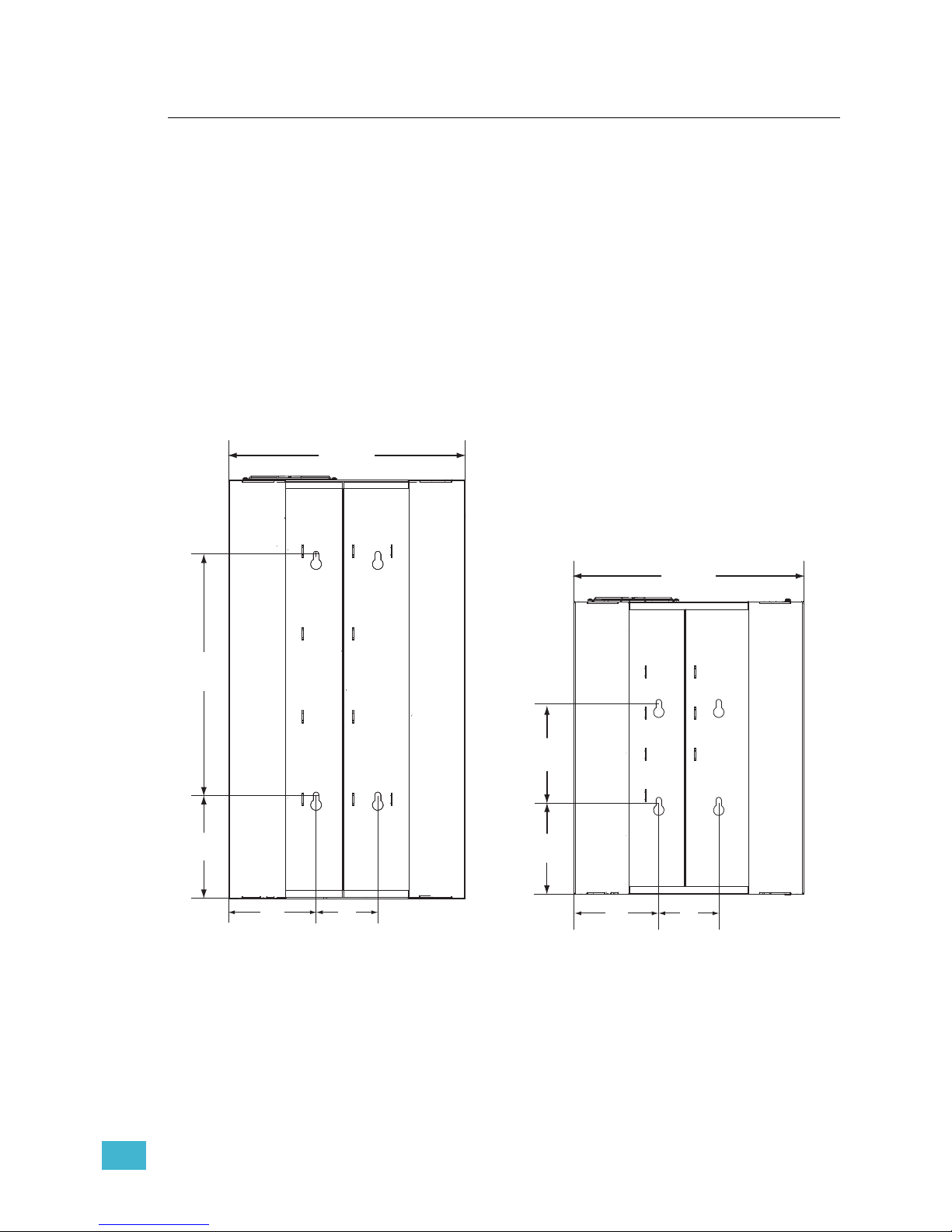
Step 2: Use the measured slot dimensions located in the graphic below to mark the hole
locations for the mounting hardware.
Step 3: Drill the holes and install the mounting hardware for each rack.
• Four 3/8” (M8-M10) bolts or screws 2-4” (50-100mm) long, and suitable
wall plugs are suggested mounting hardware (lag bolts recommended).
• Both the surface and the mounting hardware must support the weight of
the rack unit fully populated with modules.
• Expose at least 1” (25mm) of threads for mounting the rack.
Step 4: Attach the rack enclosure to the wall.
Step 5: Check that the rack is level and plumb and tighten the mounting hardware.
432 mm
17”
451 mm
17.75”
194mm
7.64”
113mm
4.45”
160mm
6.3”
432 mm
17”
184mm
7.25
194mm
7.64”
113mm
4.45”
160mm
6.3”
DRd12 rear panel
DRd6 rear panel
Page 18
14 Unison® DRd Rack Enclosure Installation Manual
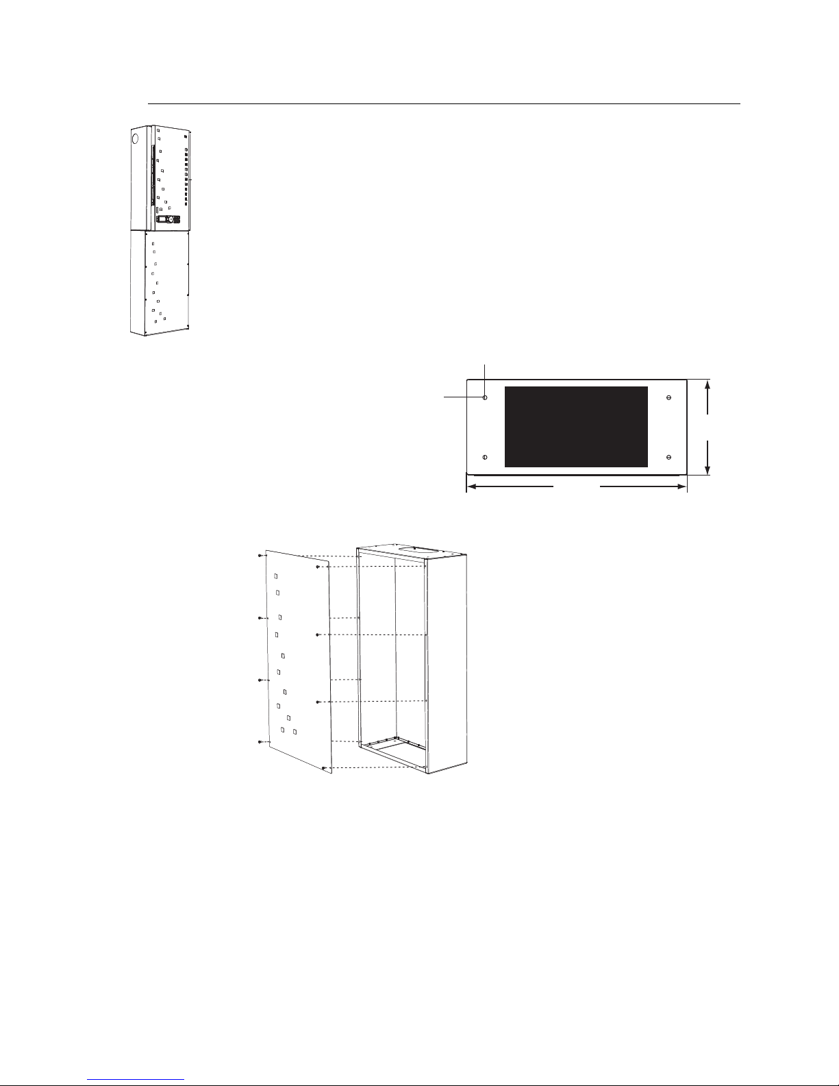
Mounting a DRd Rack Enclosure on a Pedestal
Step 3: Remove the eight screws and washers that secure the front panel to the unit.
Step 4: Position the floor stand on floor hardware previously placed for marking the
holes.
Step 5: Secure the pedestal base to the floor.
Step 6: Create conduit access in the bottom of the DRd rack. Notice the label inside the
bottom of the rack indicating the recommended locations for conduit access. Do
not create conduit access outside of the recommended locations.
Step 7: Position the DRd rack on the floor stand pedestal and align with the mounting
holes provided.
Step 8: Bolt the rack into place.
Step 9: Reinstall the front panel to the pedestal unit, replacing all hardware removed in
step 3.
The Unison DRd rack pedestal is designed with the same footprint as the Unison
dimmer rack. The acceptable conduit access in the bottom of the DRd rack overlaps the
floor stand access panel for contractor wiring and installation convenience. It is
recommended to secure a DRd rack installed on a pedestal to a wall for greater stability.
432mm
17”
186.7mm
7.35”
35.5mm
1.4”
35.5mm
1.4”
Step 1: Use the measured
dimensions in the
graphic (right) to mark
the hole locations for the
floor mounting hardware.
Step 2: Drill holes for floor
mounting hardware.
Page 19
2 Install Rack Enclosures 15
Mounting Auxiliary and DRd Rack Enclosures Together
Unison DRd and AX auxiliary rack enclosures are designed to be surface mounted on load
bearing walls in an electrical closet or a room with restricted public access. One DRd rack
may be bussed to the AX series auxiliary rack, which may contain a main circuit breaker
(MCB) or a main lug (ML) for power distribution to the adjacent DRd12 rack. Two DRd12
racks may be cross-bussed to an AX12X auxiliary rack which is designed to provide main
lug or main breaker input feed termination to the adjacent DRd12 racks.
The wall must be strong enough to hold all racks fully populated with modules, conduit and
wire. Reference “Where to Install the Rack Enclosure,” page 7 for weight, dimension and
clearance requirements.
Step 1: Determine where the enclosures will be installed using the weight and dimension
requirements detailed in “Where to Install the Rack Enclosure,” page 7.
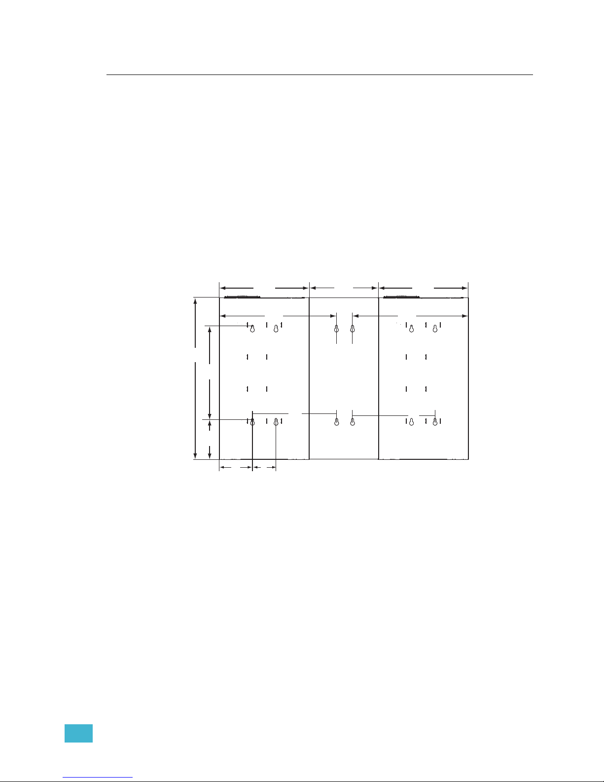
Step 2: Use the measured slot dimensions located in the graphics below to mark the hole
locations for the mounting hardware.
Step 3: Drill the holes and install the mounting hardware for each rack enclosure.
• Four 3/8” (M8-M10) bolts or screws 2-4” (50-100mm) long, and suitable
wall plugs are suggested mounting hardware per rack enclosure (lag bolts
recommended).
• Both the surface and the mounting hardware must support the weight of
the enclosures fully populated with modules.
• Expose at least 1” (25mm) of threads for mounting the rack.
Step 4: Remove the conduit knockouts from the mating side conduit plugs on the DRd
and auxiliary rack enclosures before installation. Only remove the knockouts that
are adjacent to another rack.
Step 5: Install the DRd rack first (follow instructions as outlined in “Mounting Individual
Racks on a Wall,” on page 13. Remember to install the DRd rack enclosure to
either side of the auxiliary rack in cross-bussed applications.
Step 6: Align the auxiliary rack against the DRd rack enclosure and mount it to the
previously installed hardware. Keyholes in the DRd and auxiliary rack enclosures
are aligned with each other for mounting to Unistrut or Kindorf. With conduit holes
mated, the bolt spacings are on 16” (406mm) centers (top left DRd and top left
Ax rack) for installation convenience.
432mm
17”
451mm
17.75”
194mm
7.64”
113mm
4.45”
160mm
6.3”
432mm
17”
62mm
2.44”
787mm
31”
406mm
16”
406mm
16”
330mm
13”
559mm
22”
559mm
22”
DRd12-48 rear panel view
Page 20

16 Unison® DRd Rack Enclosure Installation Manual
Step 7: Install the ETC supplied 2 1/2” (64mm) nylon insulated chase nipple and 2 1/2”
(64mm) locknut between the auxiliary and DRd rack enclosures.
Step 8: For cross-bussed DRd12-24 rack installations, install the second DRd12-24 by
following steps 4 through 7 above.
Step 9: Check that each rack is level and plumb then tighten the mounting hardware for
a secure installation.
Note:
Reference the related Auxiliary Rack Enclosure Installation Manual to complete
the auxiliary rack installation and for DRd12-24 and DRd 12-48 rack input power
bus wiring termination.
Follow the instructions in this manual for all other DRd rack enclosure installation
procedures.
Page 21

3 Rough-in Conduit and Wiring 17
Chapter 3
Rough-in Conduit and Wiring
This chapter contains instructions for conduit and wiring installation of the DRd rack
enclosure.
This chapter contains the following sections:
• Prepare the DRd Rack . . . . . . . . . . . . . . . . . . . . . . . . . . . . . . . . . . . . . . . . 18
• Remove the DRd Rack Power Supply/Dimming Engine Access Panel 18
• Modify Phase Bus for 120 VAC Split Phase Operation . . . . . . . . . . . . . 19
• Rough-in Conduit to the DRd Rack . . . . . . . . . . . . . . . . . . . . . . . . . . . . .21
Page 22
18 Unison® DRd Rack Enclosure Installation Manual
Prepare the DRd Rack
All rack terminations are accessible from the front of the rack. Reference “Wire Routing and
Specification”, page 8 for conduit access specifications.
Prior to conduit installation you should remove the power supply access panel for clear
access to the top of the DRd rack enclosure. Reference “Remove the DRd Rack Power
Supply/Dimming Engine Access Panel” below.
Take the opportunity before roughing in your conduit to change your rack for split phase
operation (100/120 VAC racks only) if required. Reference “Modify Phase Bus for 120 VAC
Split Phase Operation”, page 19.
Remove the DRd Rack Power Supply/Dimming Engine Access Panel
Remove the power supply/dimming engine access panel to allow for better access in the
top of the DRd rack enclosure while roughing in conduit and cable.
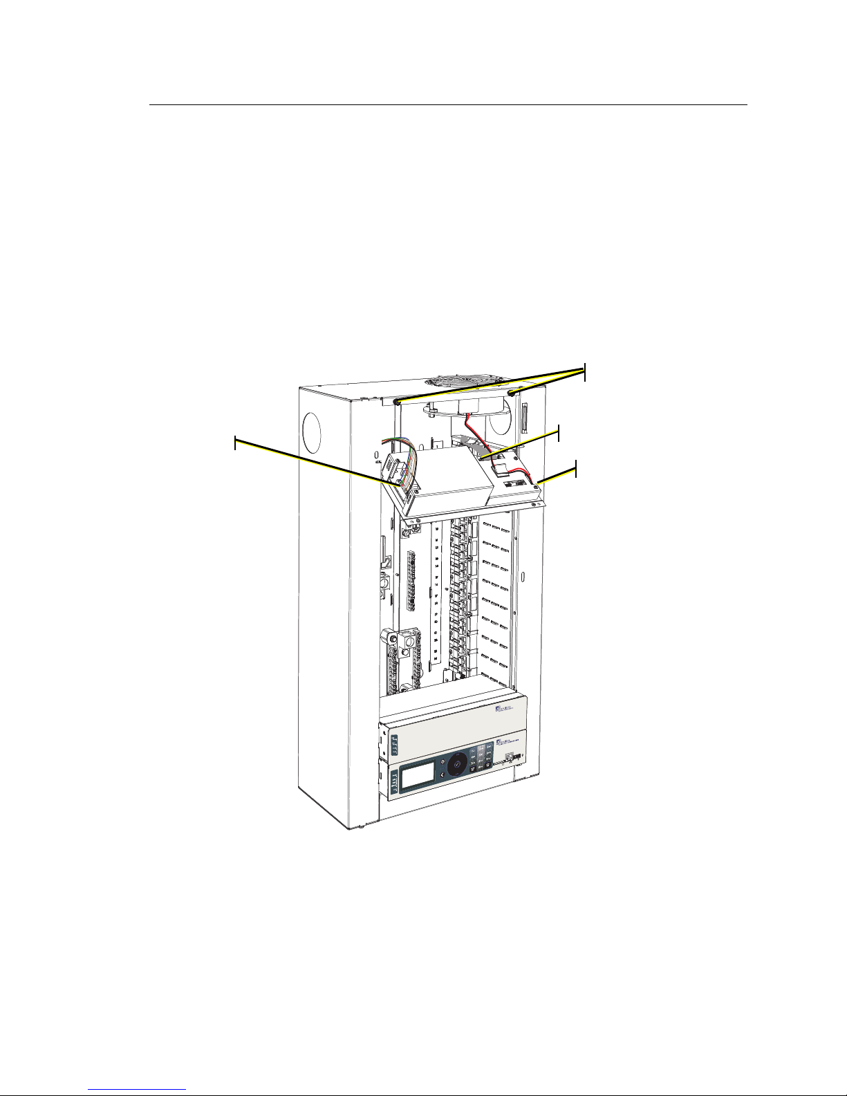
Step 1: Loosen the two captured screws that secure the access panel.
Step 2: Gently pull the panel straight down until the top of the access panel is clear of the
enclosure.
Step 3: Tilt the supply access panel away from the rack enclosure.
Step 4: Disconnect the three cables that are attached to the unit.
a: For the cable bundle on the left side, squeeze the tabs on either side of the
connector and gently pull the cable until it is free from the unit.
Step 1
Step 4.a
Step 4.b
Step 4.c
The rack door has
been removed from
this graphic for clarity
of this procedure.
Page 23
3 Rough-in Conduit and Wiring 19
b: For the ribbon cable connected on the right rear side, release the tabs on
either side of the connector by sliding them opposite the connector then
gently pull the cable free.
c: For the two-wire cable on the right side, gently pull the connector straight out.
Step 5: Remove the power supply access panel.
a: Align the panel perpendicular to the rack.
b: Slide the panel up approximately one inch to align the guide pins on the top
of the guided slots.
c: Then pull the panel straight out.
Modify Phase Bus for 120 VAC Split Phase Operation
The DRd rack can be simply changed in the field from a three phase rack to a split phase
(3 wire plus ground) rack.
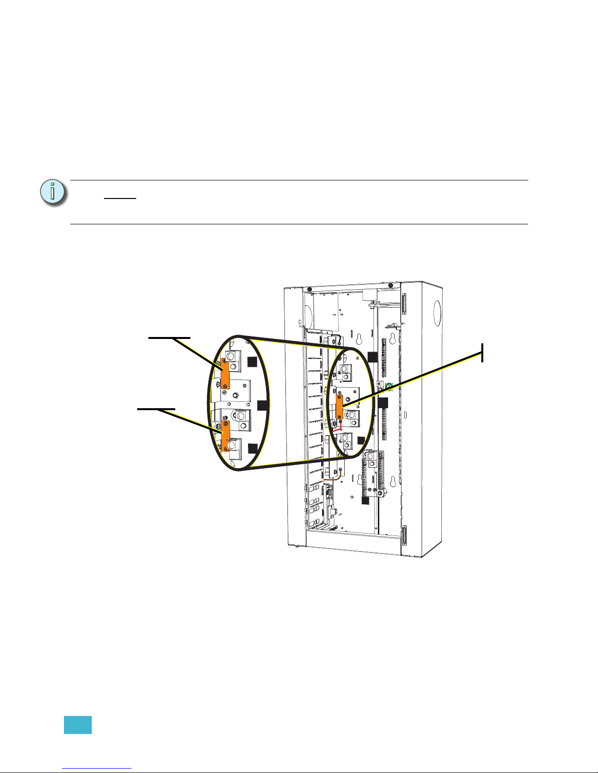
Step 1: Notice the two copper straps (stacked) on phase L2 of the rack.
Step 2: Change the DRd rack from 3Ø to 1Ø operation by moving the copper straps in
the rack, strapping the phase bars together, (reference the graphic above to
follow along).
a: Move one of the copper straps to connect between phase 1 (L1) and phase
2 (L2). The screws required are installed to the phase bars in the location the
copper strap will be mounted.
Note:
Store this access panel in a safe place until you are finished roughing in conduit
and terminations. You will need to reinstall this panel when then rack enclosure is
installed and all wires have been terminated.
L1
L2
L3
N
L1
L2
L3
Step 1:
Step 2a:
Step 2b:
The rack door has
been removed from
this graphic for clarity
of this procedure.
Page 24
20 Unison® DRd Rack Enclosure Installation Manual
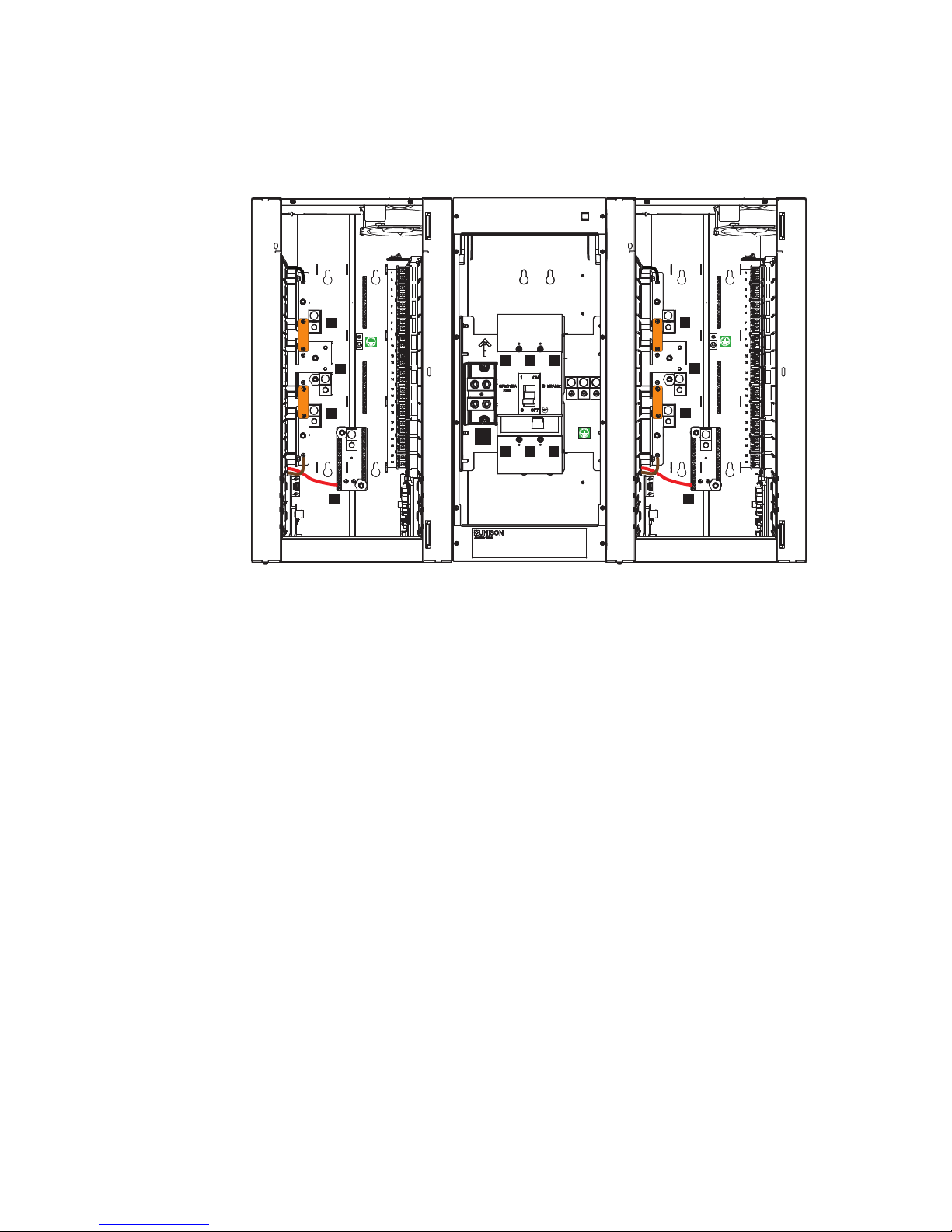
b: Remove the red sense wire from phase 2 (L2) and reroute it to the neutral
bar.
c: Move the second copper strap to connect between phase 2 (L2) and phase
3 (L3).
Step 3: For cross-bussed DRd12-48 installations, complete step 2 for both racks.
L1
L2
L3
N
N
L1
L2 L3
L1 L2 L3
L1
L2
L3
N
The rack doors
have been
removed from
this graphic for
clarity of this
procedure.
Page 25
3 Rough-in Conduit and Wiring 21
Rough-in Conduit to the DRd Rack
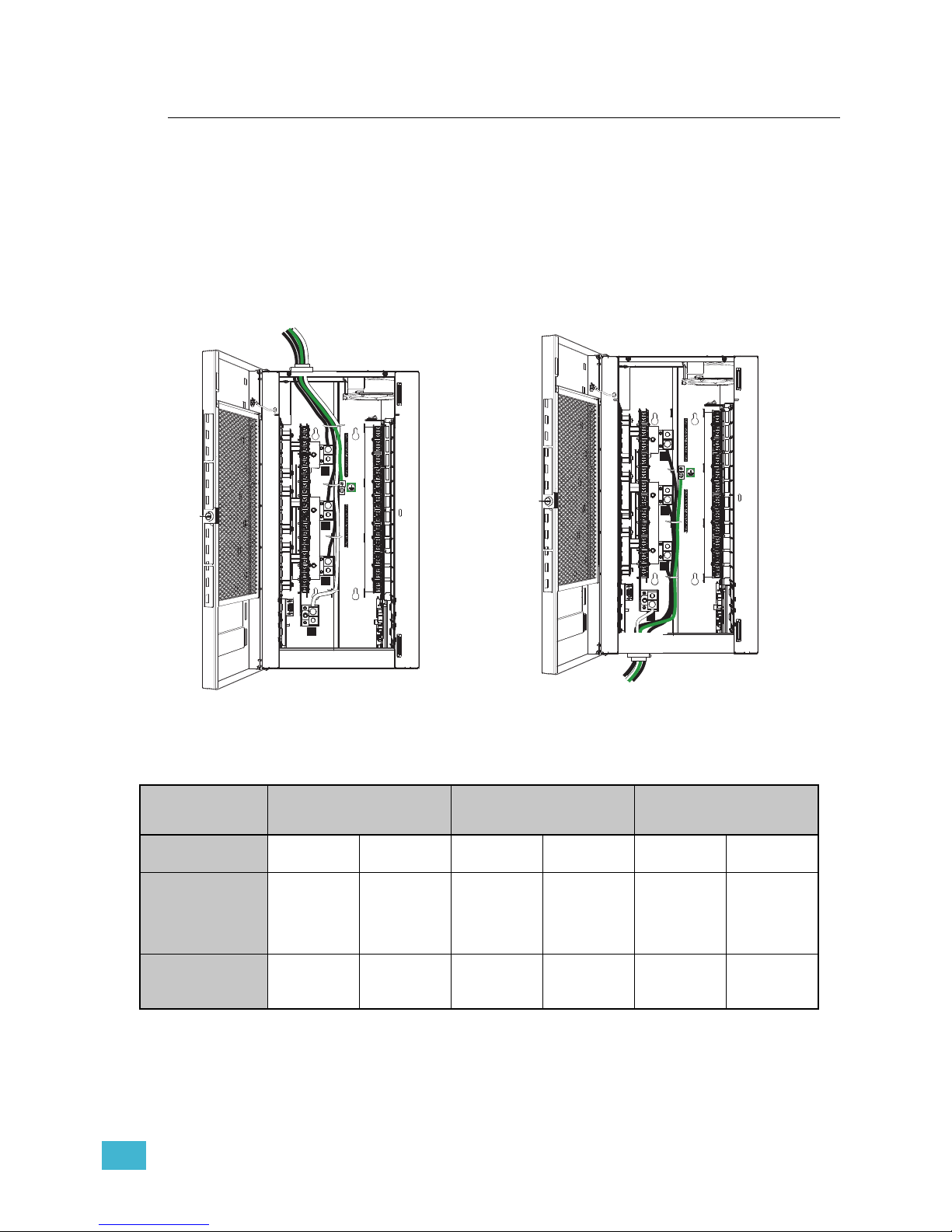
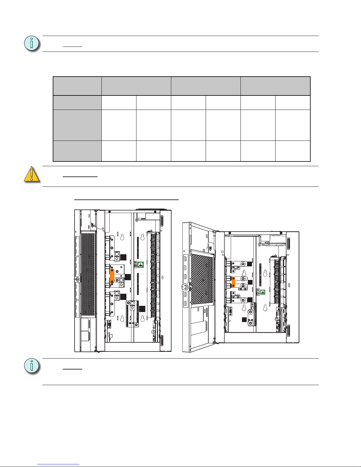
Line feed wires terminate on the main lugs provided.
The DRd12 rack is shipped from the factory with the main lugs in a top feed orientation. The
lugs can be changed to a bottom feed orientation by removing the lug mounting bolt,
rotating the lug 180°, and re-mounting the lug in the opposite lug mounting PEM. This is
true for all DRd12 rack models.
The DRd6 rack phase lugs are both top and bottom feed by default and don’t require any
change, but the neutral and ground lugs will require re-orientation for bottom feed.
When utilizing an auxiliary rack with the DRd rack, line feed wires from the auxiliary rack
enter the DRd rack through the top side conduit knockout. For cross-bussed installations
the line feed wires will be fed to the DRd rack through the conduit knockout on the adjoining
side of the auxiliary rack.
Rack Type
DRd12
120 and 230 VAC
DRd12
240 and 277 VAC
DRd6
(all models)
Lug Mounting
Bolt Torque
6 Ft-lbs 8 Nm 11 Ft-lbs 15 Nm 6 Ft-lbs 8 Nm
Wire Range
350kcmil -
1 AWG
2-6 AWG
250kcmil -
1 AWG
2-6 AWG 2/0-3 AWG 4-6 AWG
185mm
2
-
50mm
2
35mm2 -
16mm
2
120mm2 -
50mm
2
35mm2 -
16mm
2
70mm2 -
25mm
2
25mm2 -
16mm
2
Lug Wire
Tightening
Torque
375 in-lbs 200 in-lbs 375 in-lbs 275 in-lbs 50 in-lbs 45 in-lbs
42.4 Nm 22.6 Nm 42.4 Nm 31 Nm 5.65 Nm 5.1 Nm
L1
L2
L3
N
1
2
3
4
5
6
7
8
9
10
11
12
13
14
15
16
17
18
19
20
21
22
23
24
L1
L2
L3
N
1
2
3
4
5
6
7
8
9
10
11
12
13
14
15
16
17
18
19
20
21
22
23
24
Top Feed DRd rack Bottom Feed DRd rack
Page 26
22 Unison® DRd Rack Enclosure Installation Manual
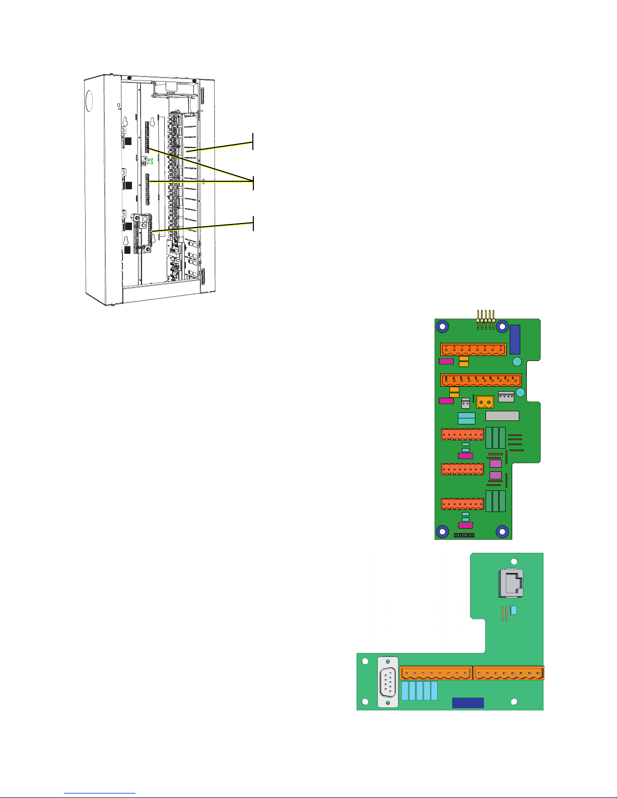
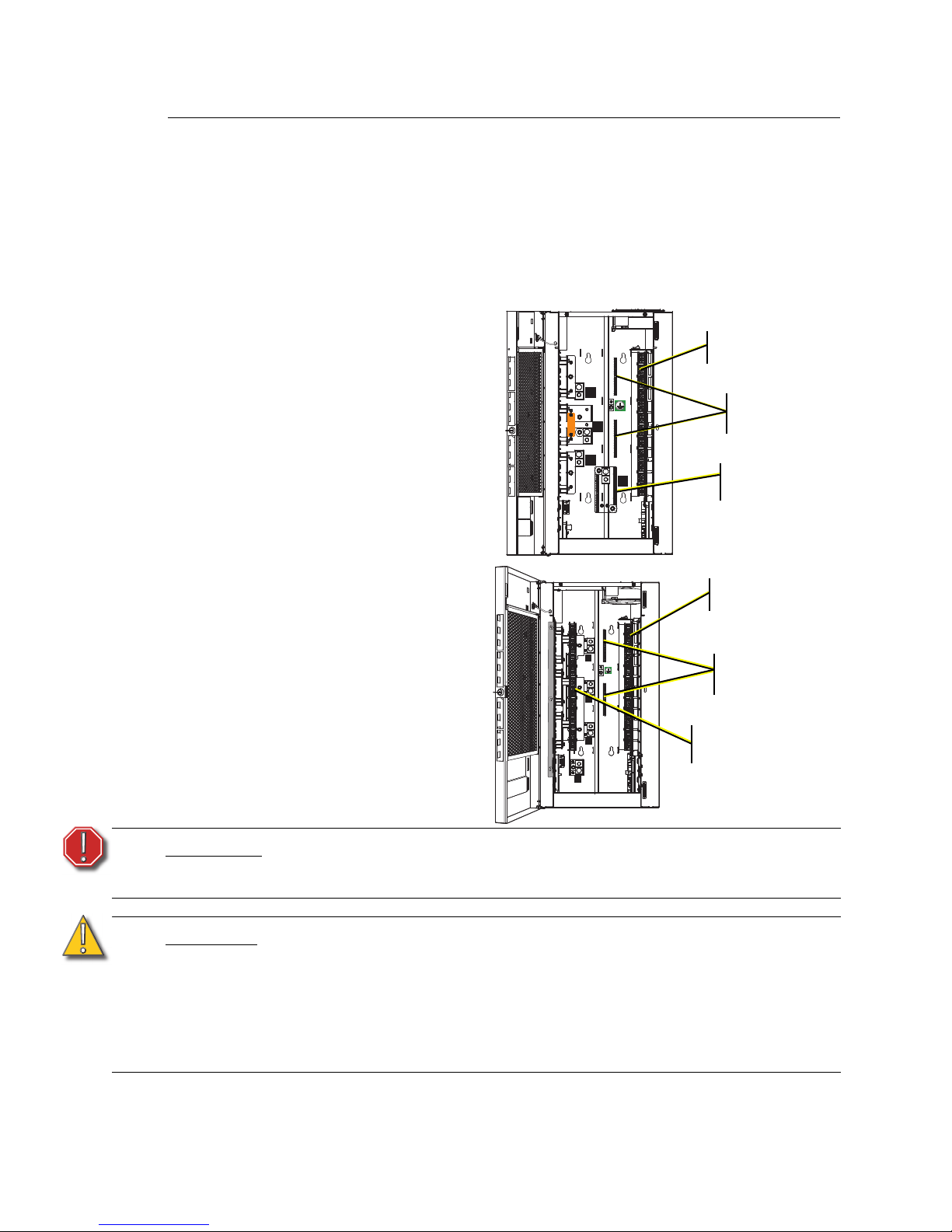
Load circuits terminate to the right side the rack enclosure.
Load wires terminate to the load lugs on the
right side of the rack.
Load neutral and load ground wires terminate
on the neutral and ground bus bars located on
the back panel of the rack enclosure. An
exception to this is made for the DRd rack with
CE neutral disconnect. Neutrals are
terminated to the neutral disconnect on the left
side of the rack. See “230 VAC Neutral
Disconnect DRd Rack” on page 27.
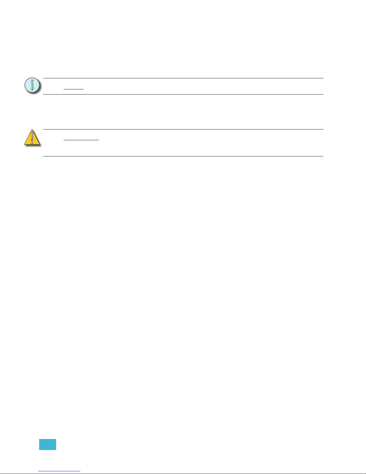
Control wires terminate to the right and left I/O boards in the
DRd rack enclosure.
Control wires can enter the dimmer rack from the top, bottom, or
either side, although ETC recommends that you pull control
wires into the rack from the bottom since all control terminations
are located near the bottom of the rack.
The right I/O board is shipped standard with all DRd rack
enclosures and includes terminations for:
• 24 Vdc Auxiliary Power input and output connector
• LON Link Power connector
• UL 924 emergency contact input for control bypass
• Auxiliary rack (Dual Rack) cross-bussed interconnection
• (2) DMX connections and a DMX pass-through connection
• All rack option connections including DALI, FLO, Unison ride
thru option (URTO) / Unison battery pack option (UBPO)
The left I/O board is required only when using
a Paradigm Architectural Control Processor
(P-ACP).
The left I/O includes terminations for:
• Ethernet
•RS232
• Contact closure terminations (4 input and
4 output)
L1
L2
L3
N
1
2
3
4
5
6
7
8
9
10
11
12
13
14
15
16
17
18
19
20
21
22
23
24
Load Hot / Live
Load Neutral
Load Ground /
Earth
The rack door has
been removed from
this graphic for clarity
of this procedure.
S
IGNAL DISTRO
R
IDE THRU/BATT
J9
DUAL RACKS
LPS
APM
DMXB
FLUOR / DALI
AUX POWER
LON LINK POWER /
CDI
DMXB
DMX
DMXA
DMX PASS-THRU
B+ B- COM A+ A- COM
7183B4606
REV
F
© 2013
ETC
,
INC
.
MADE
IN
THE
U
.
S
.
A
.
B+ B- COM
OFF
END
SOURCE
COM PANIC
A
+ A-
COM
NO4
COM4
NO3
COM3
NO2
COM2
NO1
COM1
IN4
GND
IN3
GND
IN2
GND
IN1
GND
OUTPUTSINPUTS J4 J5
7183B4605 REV
© 2008 ETC, INC.
MADE IN THE U.S.A.
RS-232
J3
J2 ETHERNET
1
6
Page 27
3 Rough-in Conduit and Wiring 23
Procedure
Step 1: Plan wire entry to the rack. See “Wire Routing and Specification” on page 8.
Step 2: Make the desired conduit access (top, bottom, left or right) from the rack. Read
and comply with the label inside the rack which details the recommended access
locations for conduit entry into the rack.
Step 3: Punch holes and install conduit fittings or insert lining materials in conduit
opening.
Step 4: Be sure there are minimal air gaps. See “Sealing Rack Air Leaks” on page 52.
Note:
Do not run power and control cable in the same conduit.
CAUTION:
Wire openings must have fittings, bushings, grommets or fiche paper lining
material to protect the wire and cable insulation from damage by sharp metal
edges, and to prevent air leaks.
Page 28

24 Unison® DRd Rack Enclosure Installation Manual
Chapter 4
Terminate Wiring
This chapter contains the following sections:
• Connect Line Power Wiring . . . . . . . . . . . . . . . . . . . . . . . . . . . . . . . . . . . 25
• Connect Load Wires . . . . . . . . . . . . . . . . . . . . . . . . . . . . . . . . . . . . . . . . . 28
• Fluorescent Load Wiring. . . . . . . . . . . . . . . . . . . . . . . . . . . . . . . . . . . . . . 30
• Connect Control Wiring. . . . . . . . . . . . . . . . . . . . . . . . . . . . . . . . . . . . . . . 32
Page 29
4 Terminate Wiring 25
Connect Line Power Wiring
Connect Line Feed in an Individual DRd Rack Installation
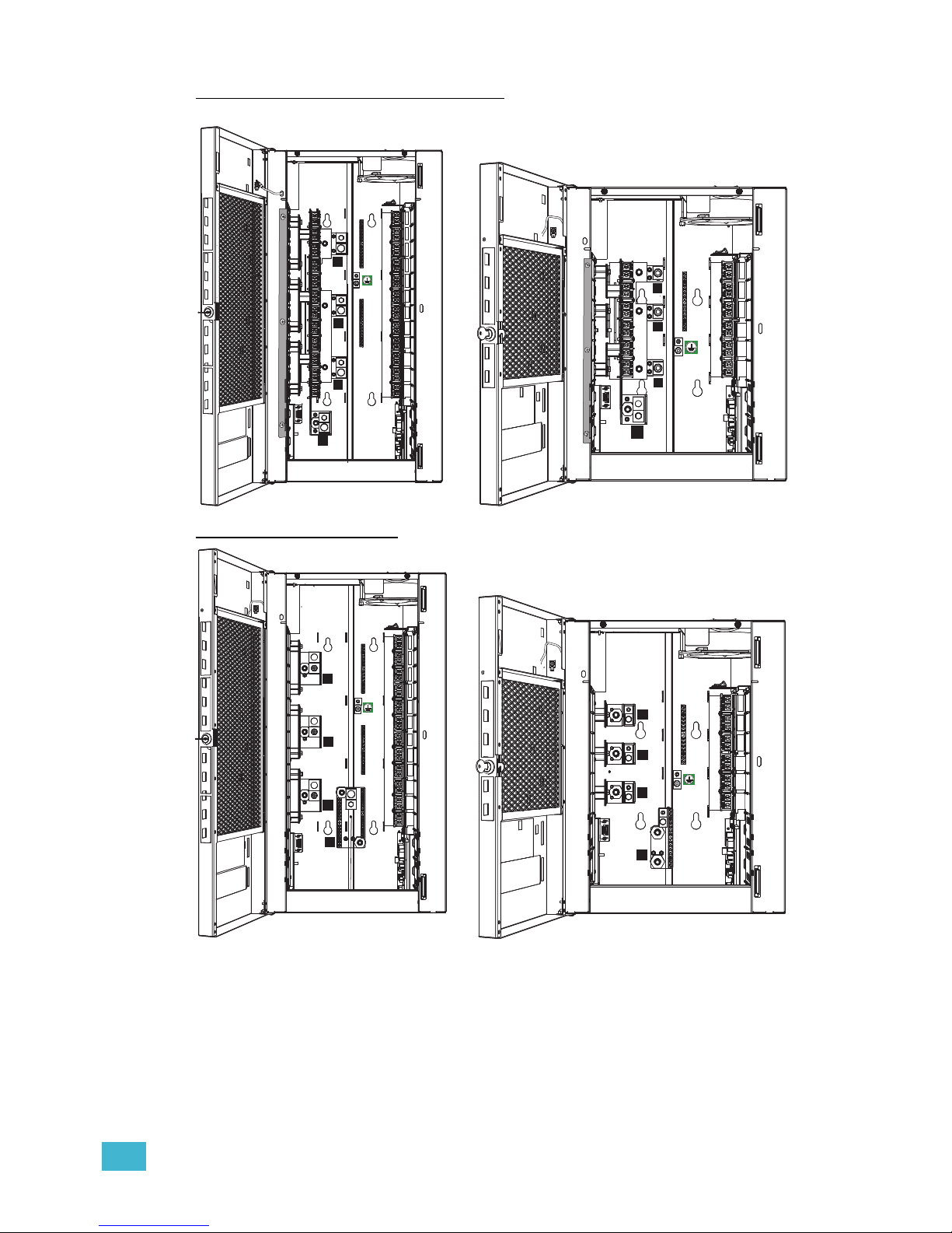
Line feed cables are terminated on the rack’s main phase lugs. It is best to route line
(feeder) cables first, load neutral and ground/earth wires next, load phase and control wires
last. In multiple rack installations, load neutral and ground/earth wires must terminate in the
same rack as the matching load phase wires.
The bus bars are different for each rack type (DRd6 or DRd12) and each rack voltage (120,
230 or 240-277). Rack graphics are located on the next page for reference.
Step 1: Pull the line phase, neutral and ground cables to the rack through the openings
(conduit or other fittings) previously prepared.
Step 2: Strip the insulation from the end of each cable and terminate them to the lugs.
Reference the table below for wire stripping lengths.
• Line and neutral connections are labeled L1, L2, L3 and N. The equipment
grounding/earthing lug is labeled with the universal grounding symbol for
easy identification.
WARNING:
All rack terminations must be done with the power off. Dimmer racks
installed without an accessible power disconnect device cannot be serviced
or operated safely. In some instances, this device may be an auxiliary rack
with a main circuit breaker. Follow all local codes and restrictions.
Before servicing, de-energize main feed to dimmer rack and follow
appropriate Lockout/Tagout procedures as described in NFPA Standard
70E. It is important to note that electrical equipment such as dimmer racks
can present an arc flash safety hazard if improperly serviced. This is due to
available large short circuit currents on the feeders of the equipment. Any
work on energized equipment must comply with OSHA Electrical Safe
Working Practices.
CAUTION:
Line and load wires used with the Unison DRd racks must be copper. Do not use
aluminum wire.
Note:
For DRd6 and DRd12 main lug, main breaker, and cross-bussed applications,
reference the Unison Auxiliary Series Rack Installation Manual.
Rack Model
Hex Key Size / Wire Strip Length
Phase
Strip
Length
Neutral
Strip
Length
Ground/
Earth
Strip
Length
DRd6 120, 240, 277 VAC
3/16” /
5mm
5/8” /
16mm
3/16” /
5mm
5/8” /
16mm
3/16” /
5mm
5/8” /
16mm
DRd6 230 VAC
5/16” /
8mm
1” / 25mm
5/16” /
8mm
1” / 25mm
3/16” /
5mm
5/8” /
16mm
DRd12 240, 277 VAC
5/16” /
8mm
1” / 25mm
3/8” /
10mm
1” / 25mm
3/16” /
5mm
5/8” /
16mm
DRd12 120, 230 VAC
3/8” /
10mm
1” / 25mm
3/8” /
10mm
1” / 25mm
3/16” /
5mm
5/8” /
16mm
Page 30
26 Unison® DRd Rack Enclosure Installation Manual
Step 3: Tighten the lugs to the correct torque based on cable size. Torque ratings are
also labeled in the DRd rack enclosure for your convenience.
100, 120, 127 VAC, 3Ø DRd Racks
Note:
CE racks are supplied with ANSI hex wrenches for line feed terminations.
Rack Type
DRd12
120 and 230 VAC
DRd12
240 and 277 VAC
DRd6
(all models)
Lug Mounting
Bolt Torque
6 Ft-lbs 8 Nm 11 Ft-lbs 15 Nm 6 Ft-lbs 8 Nm
Wire Range
350kcmil -
1 AWG
2-6 AWG
250kcmil -
1 AWG
2-6 AWG 2/0-3 AWG 4-6 AWG
185mm2 -
50mm
2
35mm2 -
16mm
2
120mm2 -
50mm
2
35mm2 -
16mm
2
70mm2 -
25mm
2
25mm2 -
16mm
2
Lug Wire
Tightening
Torque
375 in-lbs 200 in-lbs 375 in-lbs 275 in-lbs 50 in-lbs 45 in-lbs
42.4 Nm 22.6 Nm 42.4 Nm 31 Nm 5.65 Nm 5.1 Nm
CAUTION:
Dress wires neatly and avoid leaving extra wire inside the rack. Too much clutter
can restrict airflow and cause rack overtemp errors.
Note:
For 120 VAC single phase installation you must modify the phase bus before
connecting wiring. See “Modify Phase Bus for 120 VAC Split Phase Operation” on
page 19.
1
2
3
4
5
6
7
8
9
10
11
12
L1
L2
L3
N
L1
L2
L3
N
1
2
3
4
5
6
7
8
9
10
11
12
13
14
15
16
17
18
19
20
21
22
23
24
Page 31
4 Terminate Wiring 27
230 VAC Neutral Disconnect DRd Rack
240, 277 VAC DRd Racks
L1
L2
L3
N
1
2
3
4
5
6
7
8
9
10
11
12
13
14
15
16
17
18
19
20
21
22
23
24
L1
L2
L3
N
1
2
3
4
5
6
7
8
9
10
11
12
L1
L2
L3
N
1
2
3
4
5
6
7
8
9
10
11
12
L1
L2
L3
N
1
2
3
4
5
6
7
8
9
10
11
12
13
14
15
16
17
18
19
20
21
22
23
24
Page 32
28 Unison® DRd Rack Enclosure Installation Manual
Connect Load Wires
Load wires are terminated to the load lugs on the right side of the rack. In 120 VAC and
240/277 VAC DRd racks, load neutral and load ground wires are terminated to the terminal
strips on the back panel of the rack. In 230 VAC rack types, load neutrals are connected to
the left side of the rack, stacked on top of the input feeds to maintain a true neutral
disconnect.
Phase balancing of the loads is set from within the Architectural Control Processor (ACP)
“Dimmer Setup” menu. Reference the related Architectural Control Processor configuration
manual for details.
WARNING:
Use of emergency modules (ED15AFE or ER15AFE) in CE 230V DRd rack
enclosures require the neutral (N) lug in place of the neutral jumper per
module.
CAUTION:
A two-wire circuit with separate hot/live and neutral conductors is required for
every branch circuit that will be connected to the Unison DRd rack. Shared neutral
(multi wire) branch circuit arrangements are not recommended for phase-control
dimming systems due to harmonics and potentially elevated neutral currents in a
shared neutral arrangement.
For retrofit installations where shared neutral circuits are already installed, or track
lighting installations where the track has a shared neutral, consult ETC Technical
Services for rack installation guidelines.
L1
L2
L3
N
1
2
3
4
5
6
7
8
9
10
11
12
13
14
15
16
17
18
19
20
21
22
23
24
Load wire phase
Load wire
ground bus
Load wire
neutral bus
120, 240, and 277 VAC DRd
racks share similar load lugs.
L1
L2
L3
N
1
2
3
4
5
6
7
8
9
10
11
12
13
14
15
16
17
18
19
20
21
22
23
24
Load wire phase
Load wire
ground bus
Load wire
neutral bus
230 VAC DRd racks have a
neutral disconnect bus structure.
This design places neutral lugs
on the same side of the rack as
the main feeds. Neutral output
lugs are numbered on the filter
PCB. It is important to wire hot
and neutral from each load to the
corresponding numbered
outputs.
Page 33
4 Terminate Wiring 29
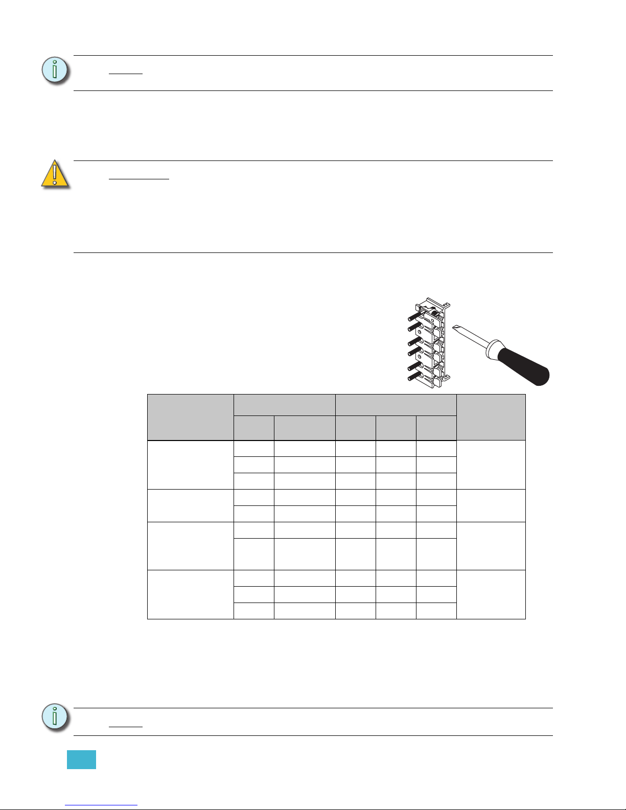
Step 1: Route the load wires to the DRd rack(s) through the conduit previously installed.
Step 2: Prepare the load wires for termination:
a: Label each wire in the set with circuit designation.
b: Separate load circuit wires into ground, neutral and hot/live wire bundles.
Step 3: Strip 5/8” (16mm) of insulation from the end of each load wire.
Step 4: Route each load hot/live wire to its individual load output connection.
Step 5: Strip the neutral wire to the length indicated in the table above and terminate to
the neutral terminal assembly. Torque to the recommended value also indicated
in the table above. For 230 VAC DRd racks, the neutral bus is located on the line
input feed side of the rack.
Step 6: Strip the ground/earth wires to the length indicated in the table above and
terminate to the ground bus terminal. Torque to the recommended value also
indicated in the table above.
Note:
Plan load wiring appropriately to avoid splicing wiring in the racks. Only one load
wire per load terminal.
CAUTION:
Dress and terminate wires neatly and avoid leaving extra wire inside the rack. Too
much clutter (especially along the right side of the rack) can restrict air circulation
and reduce cooling efficiency. If cabling interferes with airflow during operation,
the rack may be forced to shut down due to overheating.
Load wires should not cross between racks. Instead, they should enter the rack in
which they will be terminated. Hot/Live and neutral load wiring must follow the
same conduit/path for each circuit.
Connection
Cable Size Torque
Wire Strip
Length
AWG
mm
2
lbf-in lbf-ft N - m
15 - 20 amp
load lugs
14 - 10 2.5 - 6 35 2.9 4.0
5/8” - 16mm8 10 40 3.3 4.5
6 - 4 16 45 3.8 5.1
Ground bus
14 - 8 2.5 - 6 75 6.3 8.5
5/16” - 8mm
6 - 4 16 110 9.2 12.4
Neutral bus
(excluding
230 VAC)
14 - 8 2.5 - 6 75 6.3 8.5
5/16” - 8mm
6 - 4 16 110 9.2 12.4
Neutral
Disconnect
(230 VAC only)
14 - 10 2.5 - 6 35 2.9 4.0
5/8” - 16mm8 10 40 3.3 4.5
6 - 4 16 45 3.8 5.1
Note:
Ground connections must use all metal nuts and lock washers.
a: Insert the wire on the back side of the lugs.
b: Torque the lug screw to the recommended
value indicated in the table below.
Page 34
30 Unison® DRd Rack Enclosure Installation Manual
Fluorescent Load Wiring
3-wire Fluorescent
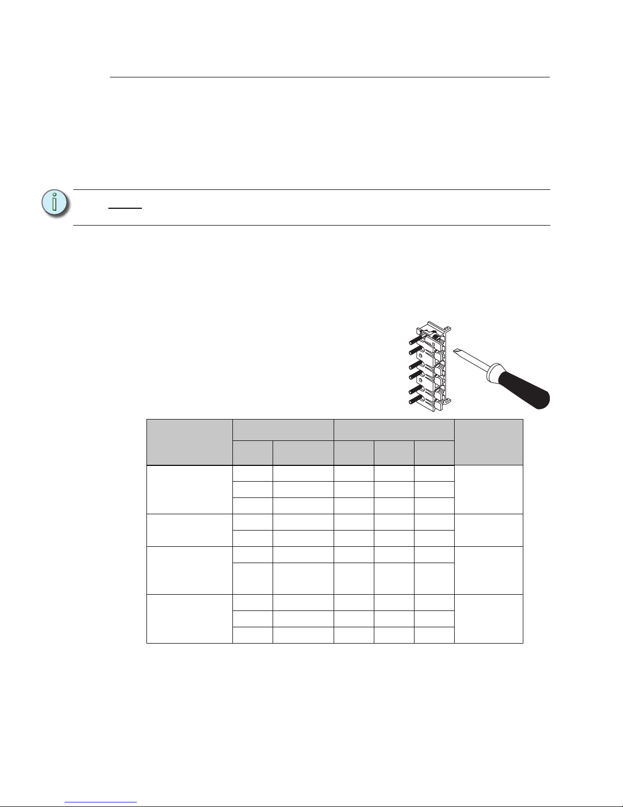
To control 3-wire fluorescent ballasts, the power circuit in the rack must be configured as a
fluorescent module type (D15F, D20F, AD15F, AD20F,HD25F), which is a single density
module, with a 2/3 wire fluorescent dimmer mode assignment. Reference the related
Architectural Control Processor Configuration Manual (SmartLink ACP or Paradigm ACP)
for instructions on changing the dimmer mode.
Step 1: Pull the three wire fluorescent ballast wiring into the DRd rack enclosure per the
wire entry plan.
Step 2: Strip 5/8” (16mm) of insulation from the end of each load wire.
Step 3: Terminate the black switched hot/live wire to the top terminal in its assigned
dimmer lug pair. Insert the wire between the back of the lug and the pressure
plate as shown.
Step 4: Terminate the dimmed hot/live wire to the bottom terminal in its assigned dimmer
lug pair. Insert the wire between the back of the lug and the pressure plate as
shown in the graphic above. Torque the wire to the recommended value in the
torque table above.
Step 5: Strip the neutral wire to the length indicated in the table above and terminate to
the neutral terminal assembly. Torque to the recommended value also indicated
in the table above.
Note:
Even though two lugs are used, the configuration (as found in the Dimmer Setup
menu of the ACP) refers only to the top (odd) number lug.
Connection
Cable Size Torque
Wire Strip
Length
AWG
mm
2
lbf-in lbf-ft N - m
15 - 20 amp
load lugs
14 - 10 2.5 - 6 35 2.9 4.0
5/8” - 16mm8 10 40 3.3 4.5
6 - 4 16 45 3.8 5.1
Ground bus
14 - 8 2.5 -6 75 6.3 8.5
5/16” - 8mm
6 - 4 10 110 9.2 12.4
Neutral bus
(excluding
230 VAC)
14 - 8 2.5 -6 75 6.3 8.5
5/16” - 8mm
6 - 4 10 110 9.2 12.4
Neutral
Disconnect
(230 VAC only)
14 - 10 2.5 - 6 35 2.9 4.0
5/8” - 16mm8 10 40 3.3 4.5
6 - 4 16 45 3.8 5.1
a: Insert the wire on the back side of the lugs.
b: Torque the lug screw to the recommended
value indicated in the table below.
Page 35
4 Terminate Wiring 31
Step 6: Strip the ground/earth wires to the length indicated in the table above and
terminate to the ground bus terminal. Torque to the recommended value also
indicated in the table above.
2-wire Fluorescent
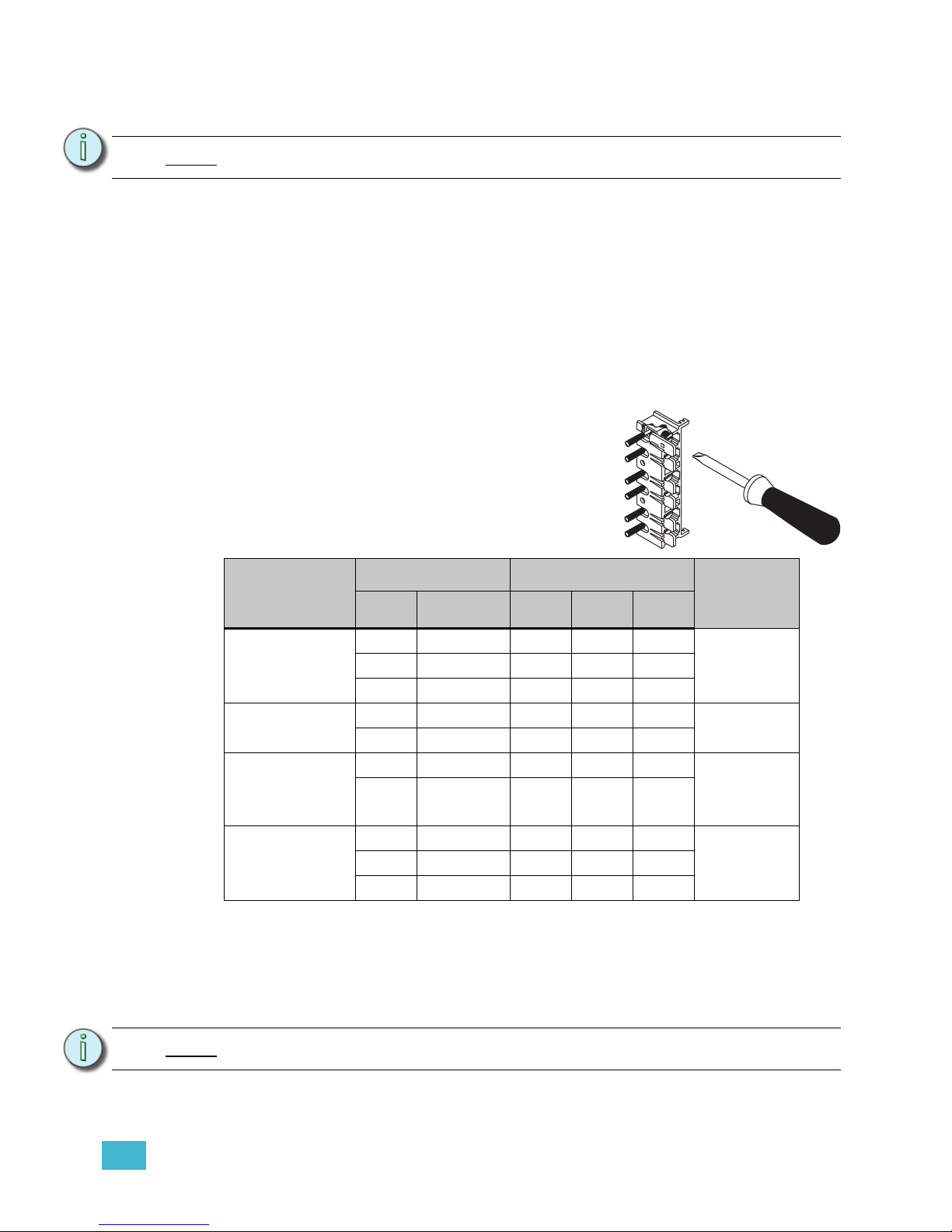
To control 2-wire fluorescent ballasts, the power circuit in the rack must be configured as a
standard module type (D15, D20, AD15, AD20, ED15, ED25, HD15, HD25) with a 2/3 wire
fluorescent dimmer mode assignment. Reference the related Architectural Control
Processor programming guide for instruction to change dimmer mode.
Step 1: Pull fluorescent ballast power wiring into the DRd rack enclosure per the wire
entry plan.
Step 2: Strip 5/8” (16mm) of insulation from the end of each load wire.
Step 3: Terminate the load wire (typically black) to the assigned dimmer lug by inserting
wire between the back of the lug and the pressure plate.
Step 4: Strip the neutral wire to the length indicated in the table above and terminate to
the neutral terminal assembly. Torque to the recommended value also indicated
in the table above.
Step 5: Strip the ground/earth wires to the length indicated in the table above and
terminate to the ground bus terminal. Torque to the recommended value also
indicated in the table above.
Note:
Ground connections must use all metal nuts and lock washers.
Connection
Cable Size Torque
Wire Strip
Length
AWG
mm
2
lbf-in lbf-ft N - m
15 - 20 amp
load lugs
14 - 10 2.5 - 6 35 2.9 4.0
5/8” - 16mm8 10 40 3.3 4.5
6 - 4 16 45 3.8 5.1
Ground bus
14 - 8 2.5 -6 75 6.3 8.5
5/16” - 8mm
6 - 4 10 110 9.2 12.4
Neutral bus
(excluding
230 VAC)
14 - 8 2.5 -6 75 6.3 8.5
5/16” - 8mm
6 - 4 10 110 9.2 12.4
Neutral
Disconnect
(230 VAC only)
14 - 10 2.5 - 6 35 2.9 4.0
5/8” - 16mm8 10 40 3.3 4.5
6 - 4 16 45 3.8 5.1
Note:
Ground connections must use all metal nuts and lock washers.
a: Insert the wire on the back side of the lugs.
b: Torque the lug screw to the recommended
value indicated in the table below.
Page 36
32 Unison® DRd Rack Enclosure Installation Manual
Connect Control Wiring
Overview
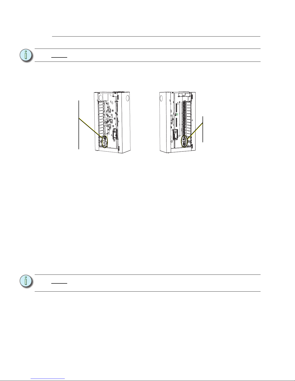
All low voltage data and option wiring connects to pluggable connectors on the left and right
input/output boards near the bottom of the DRd rack.
The DRd rack ships with a right side I/O board for low voltage control connections. A left
side I/O is available in the Paradigm termination kit.
• The left I/O is specific to use with the Paradigm Architectural Control Processor (PACP) including contact inputs and outputs, serial RS232 and Ethernet control. The left
I/O board is not compatible with the SmartLink Architectural Control Processor (SACP).
• The right side I/O is shipped with each DRd rack and provides termination for
SmartLink/LinkPower, auxiliary power, DMX in, DMX out, DMX through, and a UL 924
emergency contact input. The DRd rack supports option kits which install in the bottom
of the DRd rack for extended control and operation and terminate to the right I/O board.
Option modules include:
• Fluorescent Option Board (DRd-FLO) which provides 24 outputs for control of 4-
wire (0-10V dc) fluorescent ballasts. Each channel output is linked one - to - one
with a rack circuit for power control.
• Digital Addressable Lighting Interface (DRd-DALI) which provides 24 outputs for
control of DALI-compatible fluorescent ballasts. Each channel output of DALI
control is linked one - to - one with a rack circuit for power control (DALI Broadcast
Mode).
• Unison Ride Thru Option (URTO) kit provides power to the ACP during brief power
outages or drop outs. The URTO sustains power to the ACP for at least 12
seconds.
• Unison Battery Pack Option (UBPO) kit sustains battery power to the ACP for up
Note:
All low voltage control cables must run in separate conduit from power wires.
Note:
A DRd rack supports the use of either a DALI option board (DRd-DALI) or the FLO
option board (DRd-FLO), but not both.
1
2
3
4
5
6
7
8
9
10
11
12
13
14
15
16
17
18
19
20
21
22
23
24
3
Right I/O board ships standard with
each DRd rack
enclosure.
Left I/O board is
available as part of
the Paradigm
Termination Kit
which ships with the
Paradigm ACP.
For use only with a
Paradigm ACP.
The rack door has been
removed from these
graphics for clarity of the
procedure.
Page 37
4 Terminate Wiring 33
to 90 minutes during power outages.
DRd Right I/O Data Terminations
Auxiliary Power
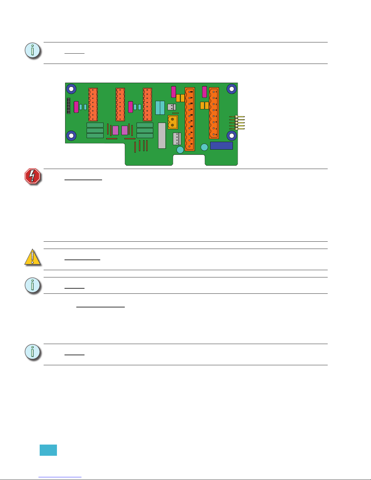
The auxiliary power connector (labeled Aux Power) provides termination for up to 16 wires
in the eight position pluggable connector. Each terminal allows up to two 16 AWG (1.5mm
2
)
wires and provides 24Vdc power to Unison control stations when used with the Paradigm
ACP. Auxiliary power is not compatible with the SmartLink ACP.
Step 1: Pull auxiliary control power wiring (typically 16 AWG (1.5mm
2
) red / black wire
pair) into the DRd rack through the conduit opening previously prepared.
Step 2: Strip 3/16” (5mm) of insulation from the ends of each wire pair.
Step 3: Remove the auxiliary power connector from the right I/O board.
Step 4: Loosen the terminal screws for as many auxiliary wire pairs as you are
terminating.
Step 5: Insert the black auxiliary power wire from the pair into a “-” terminal on the
Note:
A DRd rack supports the use of either the Unison ride thru option (URTO) or the
Unison battery pack option (UBPO), but not both.
WARNING:
RISK OF DEATH BY ELECTRIC SHOCK! Failure to disconnect all power to
the rack before working inside the rack could result in serious injury or
death.
De-energize main feed to dimmer rack and follow appropriate Lockout/
Tagout procedures as described in NFPA Standard 70E. It is important to
note that electrical equipment such as dimmer racks can present an arc
flash safety hazard if improperly serviced. This is due to available large
short circuit currents on the feeders of the equipment. Any work on
energized equipment must comply with OSHA Electrical Safe Working
Practices.
CAUTION:
DMX out and LonWorks® with LinkPower features are enabled only with the use
of the left I/O board and the Paradigm Architectural Control Processor (P-ACP).
Note:
All low voltage control cables must run in separate conduit from power wires.
Note:
It is required that you terminate SmartLink / LinkPower station wiring and the
auxiliary power wiring in the rack with the Station Power Module installed.
S
IGNAL
D
ISTRO
R
IDE
T
HRU
/B
ATT
J9
DUAL RACKS
LPS
APM
DMXB
FLUOR / DALI
AUX POWER
LON LINK POWER /
CDI
DMXB
DMX
DMXA
DMX PASS-THRU
B
+
B
-
COM
A
+
A
-
COM
7183B4606
REV F
© 2013
ETC, INC
.
MADE IN THE U.S.A
.
B
+
B
-
COM
OFF
END
SOURCE
COM
PANI C
A
+
A
-
COM
Page 38

34 Unison® DRd Rack Enclosure Installation Manual
connector and tighten the screw to secure the wire into the connector.
Step 6: Insert the red auxiliary power wire from the pair into a “+” terminal on the
connector and tighten the screw to secure the wire into the connector.
Step 7: Repeat steps 5 and 6 for each auxiliary power wire pair in the rack.
Step 8: Replace the connector on the right I/O board.
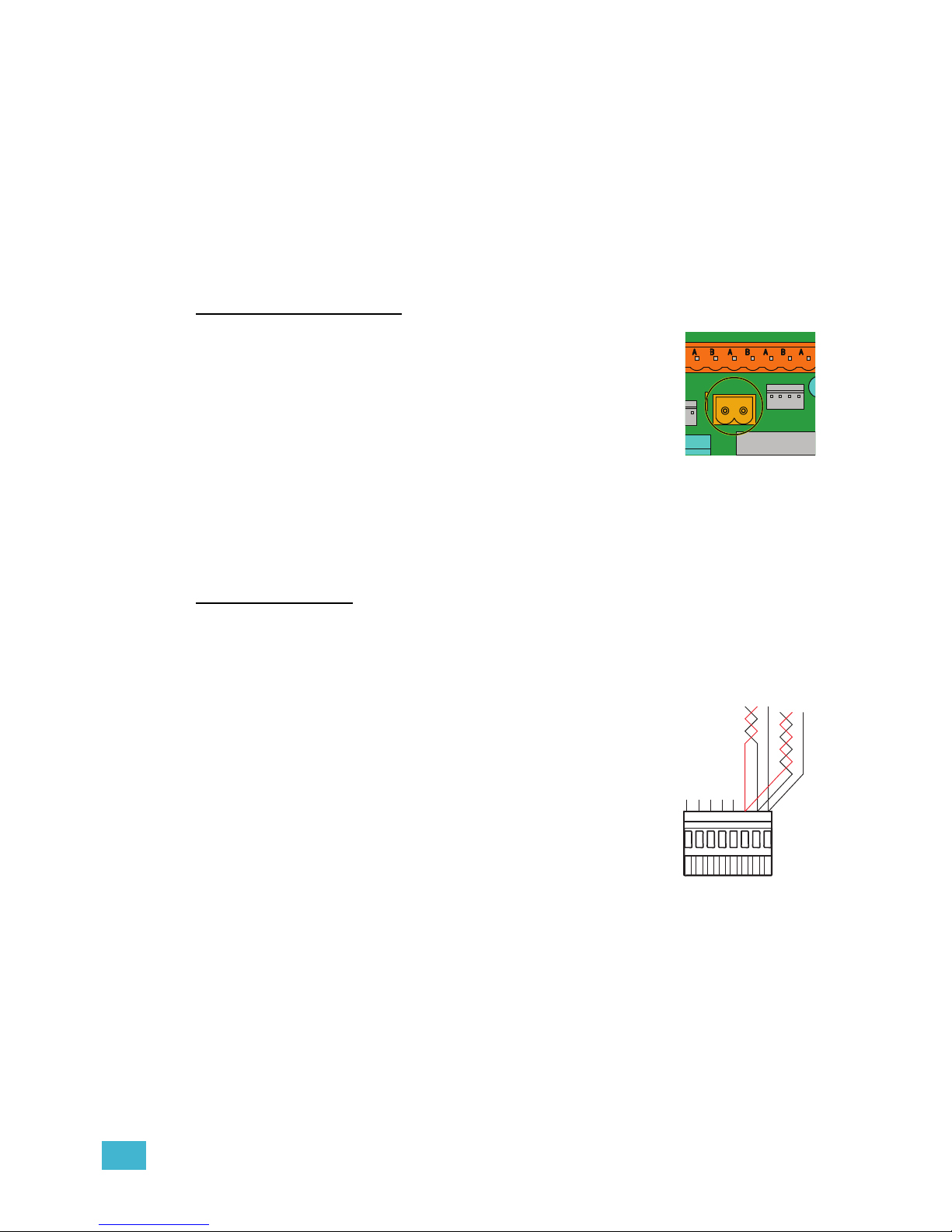
SmartLink™ / LinkPower (LON) Control Wiring
SmartLink and Unison control stations communicate with the Paradigm Architectural
Control Processor using the LinkConnect station communication bus from the Architectural
Control Processor to the stations. LinkConnect is based on Echelon
®
LonWorks® with
LinkPower bidirectional protocol, and uses one pair of wires (data+, data-).
Throughout this document, LinkConnect is referred to by the protocol it uses, LinkPower.
Termination is available for up to six home runs of LinkPower (LON) data runs utilizing
Belden 8471 cable (or approved equal) plus one 14 AWG (2.5mm
2
) ESD drain wire when
the data cable is not installed in grounded metal conduit. LinkPower wiring is topology-free
and polarity independent, you can install your LinkPower data runs in any desired
combination of bus, star, loop, and home run (up to six home run termination points
available), or any combination of these. The total combined length of LinkPower wire run
cannot exceed 1,640 feet (500m), with a maximum distance of 1,313 feet (400m) between
any two (un-repeated) communicating devices. Without a repeater, no device may be more
than 1,313 feet (400m) away from the Architectural Control Processor.
Standard LON interoperability requires that there should be a maximum of only one
repeater between any two LON devices. This means that only one repeater module,
whether a Paradigm station repeater module (P-REP) or a Paradigm dual station repeater
module (P-DREP), may be used per Paradigm Architectural Control Processor (P-ACP).
Each individual topology-free TP/FT-10 LonWorks network can have no more than 62 LON
stations with a repeater option and Paradigm Architectural Control Processor (a maximum
of 64 total devices).
While the wiring for LinkConnect in SmartLink and Paradigm systems are the same, the two
communication and control types are not interchangeable. SmartLink products are
compatible only with the SmartLink ACP, SmartLink station power module, and SmartLink
architectural control stations. Paradigm products are compatible only with the Paradigm
ACP, Paradigm station power modules, Unison Heritage architectural control stations, and
Paradigm touchscreens.
Step 1: Pull Belden 8471 (or an equal type) control wiring and a 14AWG ground into the
DRd rack through the conduit opening previously prepared.
Step 2: Strip 3/16” (5mm) of insulation from the ends of each wire pair.
Step 3: Remove the LON connector from the right I/O board.
Step 4: Loosen the terminal screws for as many wire pairs you are terminating.
Step 5: Insert each white wire (typical) from the pairs into a “B” terminal on the connector
and tighten the screws firmly to secure the wire into the connector.
Step 6: Insert each black wire (typical) from the pairs into an “A” terminal, next to the
previously installed “B” terminal on the connector and tighten the screws firmly to
secure the wire into the connector.
Note:
It is required that you terminate LinkPower station wiring and the auxiliary power
wiring in the rack the station power module will be installed.
Page 39
4 Terminate Wiring 35
Step 7: The 14 AWG (2.5mm2) ground wire can terminate in one of three ways:
• Connected between stations using Scotchlok™ connectors (3M® #314
insulation displacement connectors, ETC part number J4166).
• Grounded to metal conduit.
• If grounded metal conduit is not installed, connect the 14 AWG (green)
ground wire to the DRd rack ground bus (the same as loads are grounded
to) inside the DRd rack, and to the green/yellow striped wire connected to
the control station using a Scotchlok connector. Reference the related
station installation manual for details.
Step 8: Replace the connector to the right I/O board.
UL 924 Listed Panic Input
Termination is available for a UL 924 Listed dry contact input for
control bypass. The two pin panic connector, labeled “PANIC”,
accepts 16 AWG (1.5mm
2
) wire.
Step 1: Pull panic wiring into the DRd rack through the conduit
opening previously prepared.
Step 2: Strip 3/16” (5mm) of insulation from the ends of each
wire.
Step 3: Remove the 2 pin Panic connector from the right I/O board.
Step 4: Loosen the terminal screws.
Step 5: Insert each wire into the terminals on the connector and tighten the screws firmly
to secure the wires into the connector.
Replace the connector to the right I/O board.
DMX Control Wiring
DMX wire preparation and termination will vary with the type of wire and termination kit
being utilized. Please refer to the instructions supplied with the DMX termination kit for
specific wire preparation.
DMX Input Wire Termination using the Screw Terminals
Connector
The graphic to the left illustrates DMX termination layout for the
screw-terminal connectors that are intended for use with Belden
9729 cable (or approved equal) cable type.
Screw terminal connectors are supplied as standard in the DMX
Preparation Kit w/ Screw Connector, part number 4100A1012.
Be aware that cable other than Belden 9729 may have a different
color code for its wire pairs.
/B
ATT
J9
DUAL RACKS
CDI
COM PANI C
12345678
COM
n/c
n/c
n/c
n/c
n/c
Data + (Red)
Data - (Black)
From source
DMX A
If daisy-chaining to
another rack or
DMX device...
Page 40
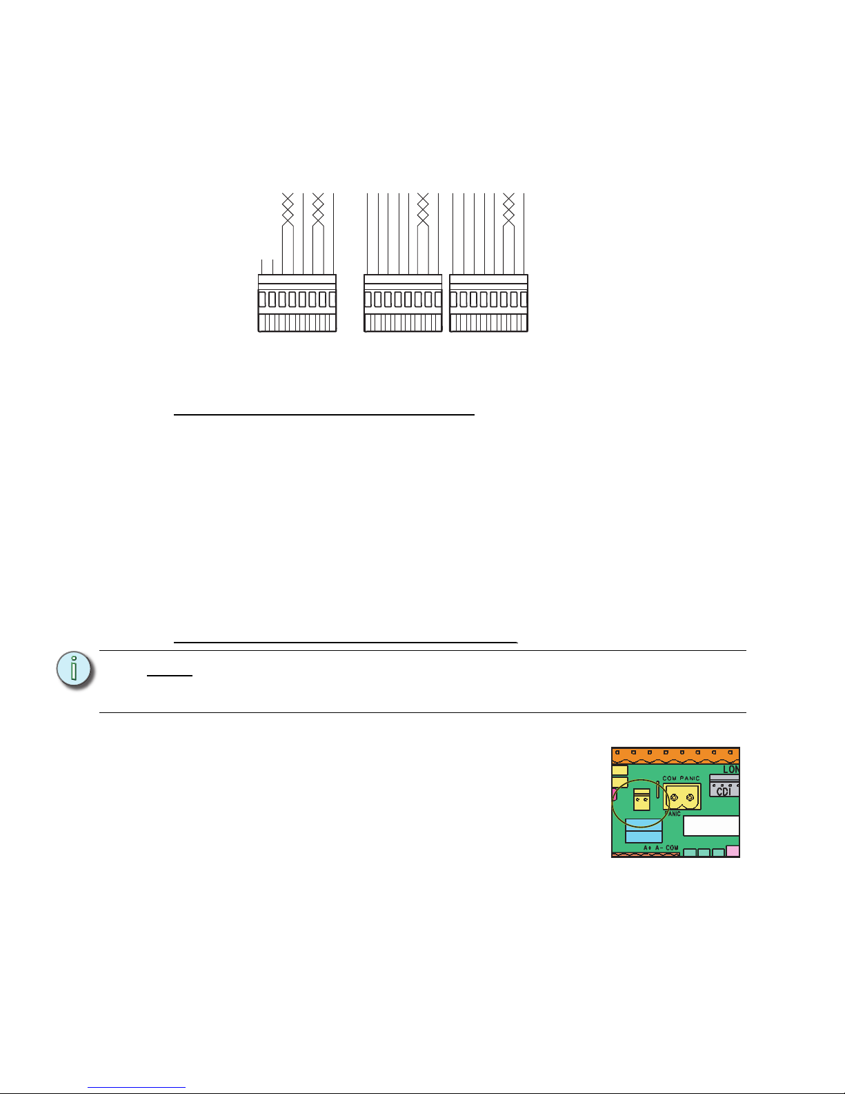
36 Unison® DRd Rack Enclosure Installation Manual
DMX Input Wire Termination using the Insulation Displacement Connector (IDC)
The graphic below illustrates DMX termination layout for an insulation displacement
connector. This connector type is intended for use with Belden 1583A (or approved equal,
such as Category 5, 5E, or 6) cable type. Be aware that cable other than Category 5 may
have a different color code for its wire pairs.
Reference and follow the DMX Cable Preparation for IDC Termination instruction sheet that
is shipped with the insulation displacement pluggable connector kit (part number
4100A1013).
AX12X Cross-bussed Rack Interconnection
Termination is provided for connection of a second DRd rack when installed in a crossbussed application. This termination point is labeled “Dual Racks” on the right I/O board.
An interconnect cable is provided which connects rack 1, which is the rack with the ACP
installed, to rack 2, which is the secondary rack in the cross-bussed rack system. This cable
is labeled at both ends, one end indicating rack 1 and the other end indicating rack 2. You
must have installed this cable to the correct rack for proper operation.
This interconnection of racks allows full control of both DRd racks from only one
Architectural Control Processor (ACP). This may only be used in a cross-bussed rack
application.
Reference the Auxiliary Rack Enclosure Installation Manual for instructions to accomplish
this termination.
Terminate the Unison Options (URTO and UBPO)
Note:
A single DRd rack supports the use of either the Unison Ride Thru Option (URTO)
board or the Unison Battery Pack Option (UBPO) board, but not both in one
enclosure.
12345678
n/c
n/c
COM
Data +
Data - ORG
W/ORG
W/BRN
COM
Data +
Data - ORG
W/ORG
W/BRN
Use the DMX Pass-Thru
connector
If daisy-chaining to
another rack or
DMX device...
DMX A
Thru
DMX B
Thru
1234567812345678
COM
Data +
Data +
Data -
Data - ORG
W/ORG
BRN
GRN
W/GRN
BLU
W/BLU
W/BRN
ORG
W/ORG
BRN
GRN
W/GRN
BLU
W/BLU
W/BRN
COM
From source
DMX A
From source
DMX B
Ride Thru/Batt
J9
DUAL RACK
L
Half
Termination is available on the right I/O for the either the Unison
Ride Through Option (URTO) or the Unison Battery Pack Option
(UBPO). You may use only one of these option kits per DRd rack.
Step 1: Notice the two pin connector labeled “Ride Thru / Batt”
on the right I/O board.
Step 2: Plug the option cable into the receptacle.
Page 41

4 Terminate Wiring 37
Terminate DMX
DMX requires 120 termination at the last DMX
device in the control run. Since a DRd rack with a
Paradigm module installed can utilize up to two DMX
inputs (2 DMX runs) the right I/O board provides
convenient termination switches for use.
Notice the two termination switches labeled DMXA
and DMXB. Each switch has three termination
positions:
• Source - reserved for RDM termination (future
development).
• Off - no termination, DMX will pass through this device on to the next DMX device in
the data run.
• End - termination is on. Used for the last DMX device (DRd rack) that is physically
connected in the daisy-chained DMX In data run.
When a Paradigm processor is used in an Unison DRd rack enclosure, port B will be
configured as an output and cannot be changed. port A is configured as either a DMX input
or output. When used as an output the DMX termination should always be set to “Off”.
When a SmartLink processor is utilized in the Unison DRd rack enclosure, port A is
automatically configured to be a DMX input and cannot be changed, port B is not used.
APM
DMXB
DMX
-THRU
B
+ B- COM
SRC
OFF END
Page 42
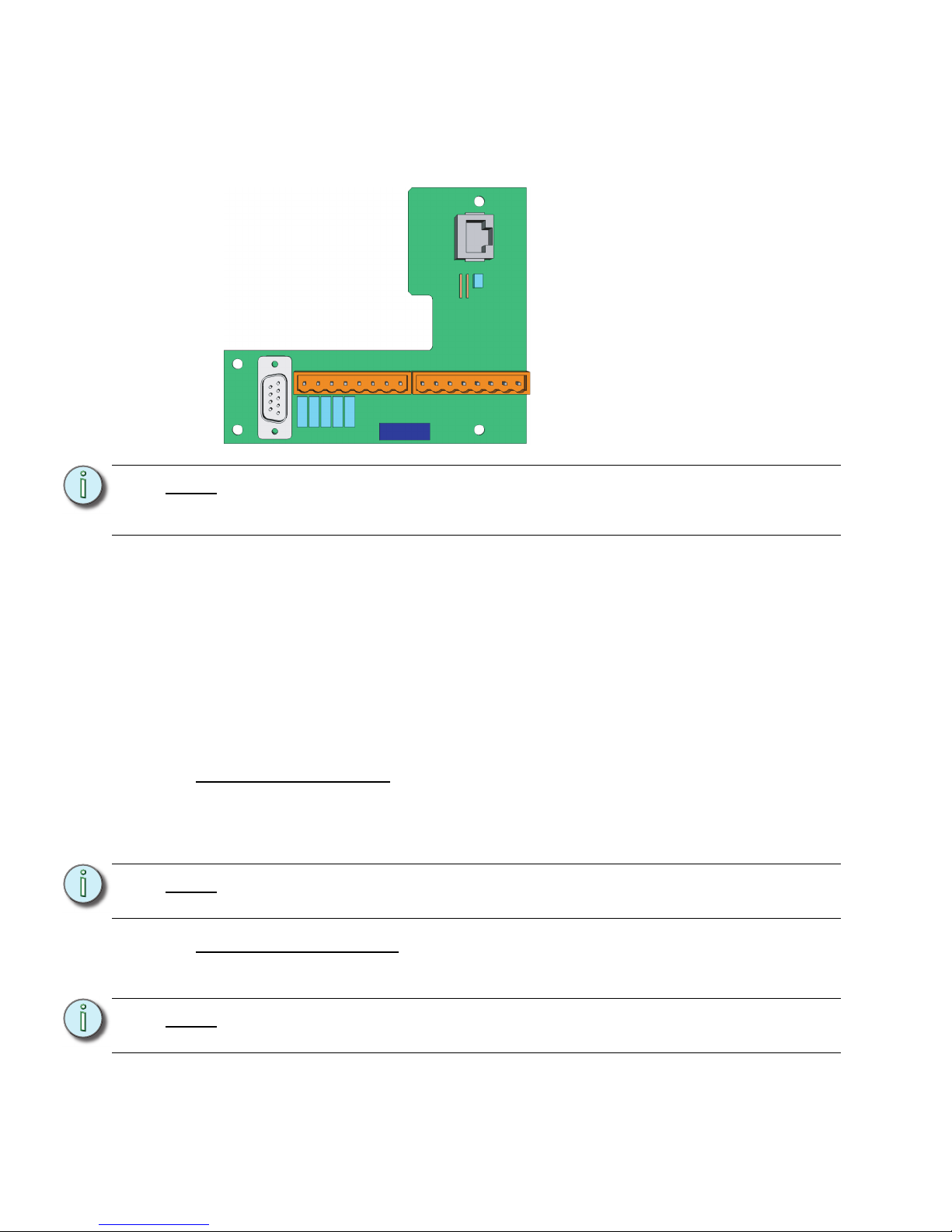
38 Unison® DRd Rack Enclosure Installation Manual
DRd Left I/O Data Termination
The left I/O board is not included with the DRd rack when shipped from the factory. Instead,
this board is provided in the Paradigm DRd termination kit (model # P-DRd-TK). The left
I/O board should be installed by the installing contractor or field technician. Follow the
instructions provided with the left I/O board for installation and wire termination.
The left I/O board supports the Paradigm Architectural Control Processor data
terminations including:
• RS-232 on a male 9 pin (D style) connector
• Ethernet on a RJ-45 female connector
• Contact closure input terminations on a 8 pin pluggable connector.
• Terminations available for 4 inputs and 4 common wires.
• Contact closure output terminations on a 8 pin pluggable connector.
• Terminations available for 4 normally open relay outputs and 4 common wires.
Connect to Serial RS-232
Integrators or users of advanced systems can interface with the Unison system through the
RS-232 connector on the left I/O board. This connection provides an interface with external
devices capable of sending or receiving RS-232. This connection can also receive serial
commands from a transmitter and provide rack and system status when queried.
Connect to Ethernet RJ-45
Network interface to the DRd rack is made through the RJ-45 connector (labeled Ethernet)
located on the left I/O board.
Note:
Data terminations to the left I/O board are specific to use with the Paradigm
Architectural Control Processor (P-ACP) and are not compatible with an installed
SmartLink Architectural Control Processor (S-ACP).
Note:
The RS-232 cable (not supplied) should follow common RS-232 pinout for a DB9
receptacle (pin 2 is RS-232 Rx, pin 3 is RS-232 Tx, and pin 5 is ground).
Note:
All Ethernet terminations must follow IEEE 802.3 and be terminated to the T568B
standard.
NO4
COM4
NO3
COM3
NO2
COM2
NO1
COM1
IN4
GND
IN3
GND
IN2
GND
IN1
GND
OUTPUTSINPUTS J4 J5
7183B4605 REV
© 2008 ETC, INC.
MADE IN THE U.S.A.
RS-232
J3
J2 E THERNET
1
6
Page 43

4 Terminate Wiring 39
Connect to Contact Inputs and Contact Outputs
The left I/O provides a convenient interface (inputs and outputs) to external devices via
contact closure on removable pluggable connectors. Up to four contact inputs are available
and can be configured for either maintained or momentary operation as setup in the
Paradigm Architectural Control Processor. Reference the Paradigm Architectural Control
Processor Programming Guide for details on configuration. Up to four contact outputs are
available and are preset for normally open operation.
Terminate Contact Inputs
Step 1: Remove the contact inputs removable screw terminal connector located on the
left I/O board. Each connector is labeled for installation convenience.
Step 2: Loosen the desired number of contact input screw terminals and related ground
screw terminals on the connector.
Step 3: Insert contact closure 1 into the terminal labeled “IN1” on the connector and
tighten the screw terminal.
Step 4: Insert the related common wire for contact closure 1 into the terminal labeled
“GND” on the connector and tighten the screw terminal.
Step 5: Repeat for each contact input and ground wire pair (up to four total).
Terminate Contact Outputs
Step 1: Remove the contact outputs removable screw terminal connector located on the
left I/O board. Each connector is labeled for installation convenience.
Step 2: Loosen the desired number of contact output (normal open) screw terminals and
related ground screw terminals on the connector.
Step 3: Insert contact output 1 into the terminal labeled “NO1” on the connector and
tighten the screw terminal.
Step 4: Insert the related common wire for contact output 1 into the terminal labeled
“COM1” on the connector and tighten the screw terminal.
Step 5: Repeat for each contact output and common wire (up to four total).
Note:
Typical contact I/O wiring is color coded as follows: contact 1 - brown, contact 2 orange, contact 3 - yellow, contact 4 - green. All commons and ground voltages
are typically black or red.
Page 44

40 Unison® DRd Rack Enclosure Installation Manual
Chapter 5
Install Rack Options
• DALI Option Kit . . . . . . . . . . . . . . . . . . . . . . . . . . . . . . . . . . . .41
• Fluorescent Option Kit . . . . . . . . . . . . . . . . . . . . . . . . . . . . . .44
• Ride Thru Option Kit . . . . . . . . . . . . . . . . . . . . . . . . . . . . . . . .46
• Battery Pack Option Kit. . . . . . . . . . . . . . . . . . . . . . . . . . . . . .47
Page 45
5 Install Rack Options 41
Install Rack Options
Unison DRd rack options include the fluorescent option kit (DRd-FLO), the digital
addressable lighting interface option kit (DRd-DALI), the ride thru option kit (URTO), and
the battery pack option kit (UBPO).
It is best to install these rack options after conduit rough-in and the line, load and control
terminations are complete to reduce the likelihood of damage to the option boards.
DALI Option Kit
Install the DALI Option Kit
The Digital Addressable Lighting Interface option kit (DRd-DALI) controls 24 loops of 64
DALI compatible fluorescent ballasts in a broadcast mode. Each of the 24 DALI loops are
linked one to one with a rack circuit for power control. For example, DALI loop 1 is controlled
by DRd rack dimmer 1, DALI loop 2 is controlled by DRd rack dimmer 2, etc.
To control DALI fluorescent ballasts, the rack circuit must be populated with a dimmer
module and assigned to DALI dimmer mode within the ACP software. Reference the
related Architectural Control Processor programming guide for instruction to change
dimmer mode.
Note:
A single DRd rack supports the use of either the DALI Option kit or the FLO Option
kit, but not both in the same rack.
In addition, a single DRd rack supports the use of either the Unison Ride Thru
Option (URTO) or the Unison Battery Pack Option (UBPO), but not both in the
same rack.
Note:
The DALI ballast is powered by an external DALI loop power supply (supplied by
others). This supply is connected externally of the DRd rack. Each DALI loop
requires its own power supply and possibly more than one power supply
depending on the load.
Page 46
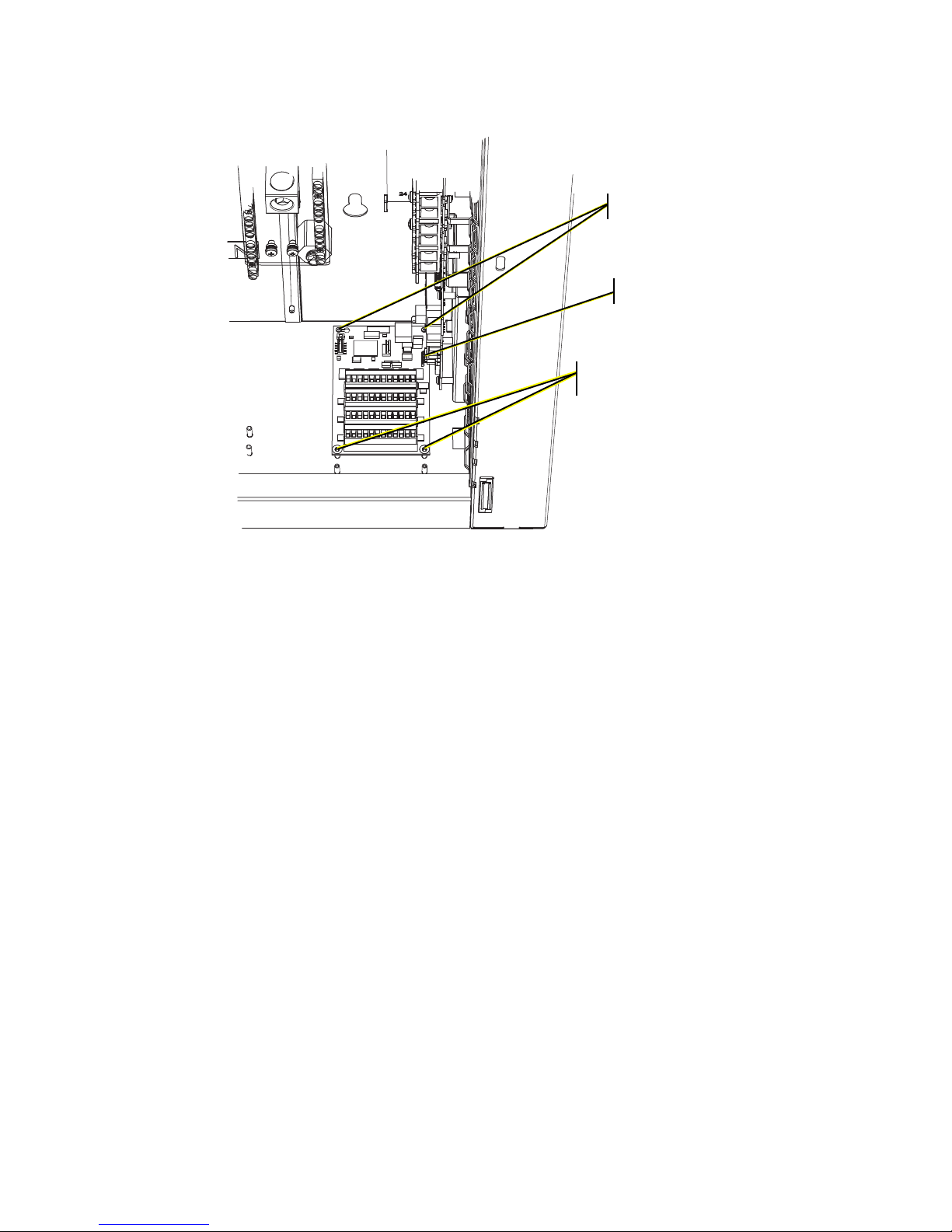
42 Unison® DRd Rack Enclosure Installation Manual
The DALI option kit supports 64 DALI compatible fluorescent ballasts per DALI loop. All
DALI fluorescent ballasts connected to that loop will respond at the same time and to the
same level as sent by the broadcast command.
Step 1: Align the DALI option board to the mounting studs in the bottom right side of the
DRd rack.
• Notice the mounting holes on the DALI option board. One is a slotted
keyhole, another is an open ended slot and the remaining two on the other
end of the board are standard mounting holes used to secure the board in
place.
Step 2: Set the rear left stud through the slotted keyhole and align the open ended slot
with the back right side mounting stud.
Step 3: Gently slide the DALI board toward the right I/O board aligning the five prong
connector to the receptacle on the I/O board.
Step 4: Secure the bottom two mounting studs with the screws provided.
Step 2:
Step 3:
Step 4:
Page 47
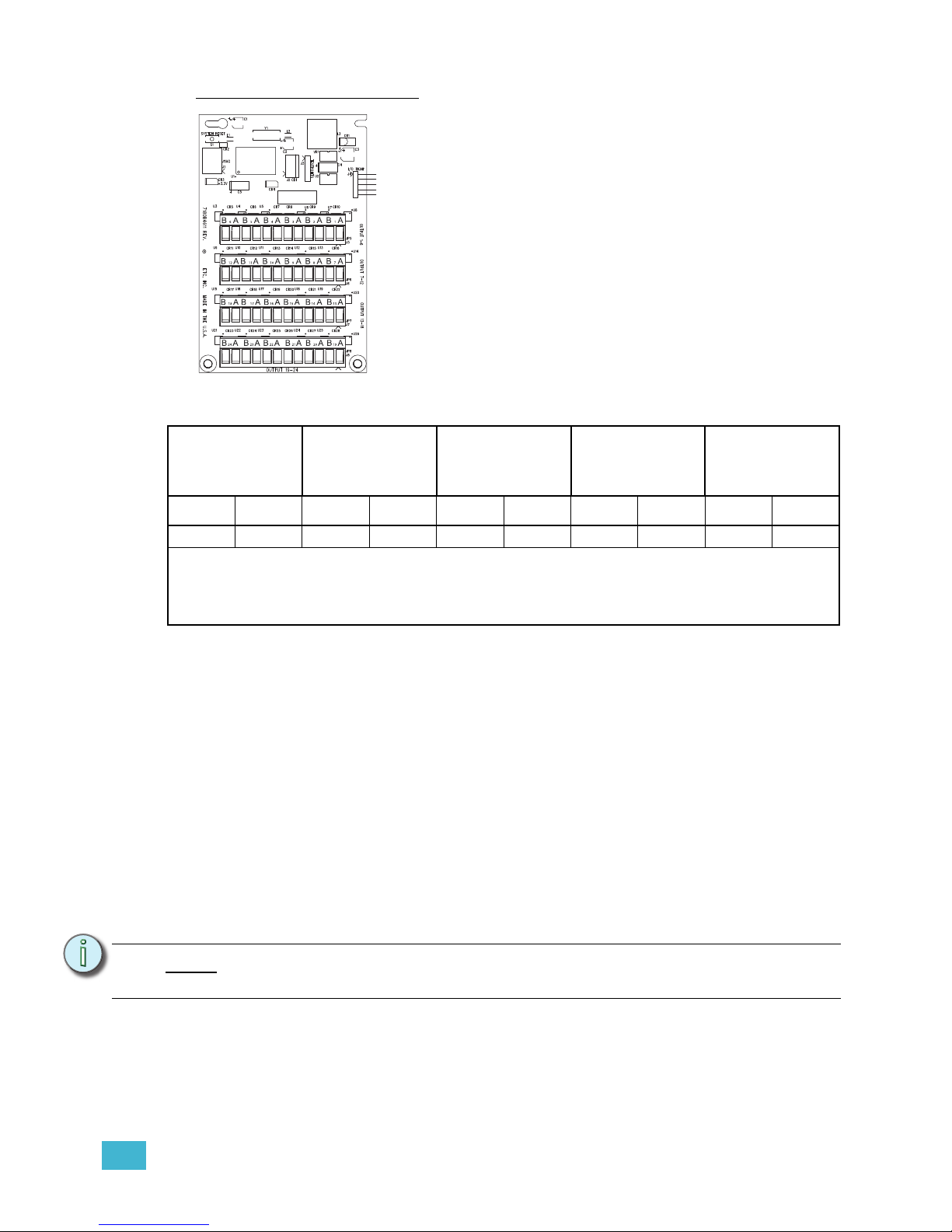
5 Install Rack Options 43
Connect DALI Option Wiring
It is important to label the DALI fluorescent ballast load and control wiring sets with the
circuit designation. Control wires terminate on the associated DALI board output loop
terminal.
For example: If circuit 1 is configured as a D20 in DALI dimmer mode, DALI fluorescent
ballast control wiring should terminate to the DALI board loop output terminals labeled “1”.
Step 1: Remove the DALI bus connector for loop outputs 1-6.
Step 2: Strip each wire in the pair back 1/4 inch (6mm).
Step 3: Using a small 3,35mm or 1/8” flat blade screwdriver, loosen the terminals and
insert each wire into the data “+” or data “-” terminals for the specific circuit loop.
Data wires in the wire set are polarity independent.
Step 4: Tighten the terminal screw until the wire is held snugly.
Step 5: Repeat steps 1 through 4 for the remaining DALI loops through loop 6.
Step 6: Replace the DALI bus connector on the DALI board and repeat for the remaining
DALI loops in the system (up to 24 loops).
*Maximum Run Lengths for Class 1 wiring
18 AWG
1mm
2
16 AWG
1.3 mm
2
14 AWG
1.6 mm
2
12 AWG
2 mm
2
**Max.
aggregate run
length
feet meter feet meter feet meter feet meter feet meter
570 175 900 275 1,430 435 2,280 700 3000 900
*Maximum Run Length - the longest distance between any device and any power supply on
the DALI bus.
**Maximum Aggregate Run Length - the longest total length of all total wiring connected to
the DALI bus.
Note:
DALI wiring can be run in the same conduit as the power wiring for the same
ballast.
2008
Label
Each of the four bus connectors on the option board provide
termination for six DALI loops. Each bus connector is labeled
for ease of loop identification and is pluggable for ease of
wiring termination. Terminals accept 12-24 (4 - .25mm
2
) AWG
Class 1 wire.
Page 48
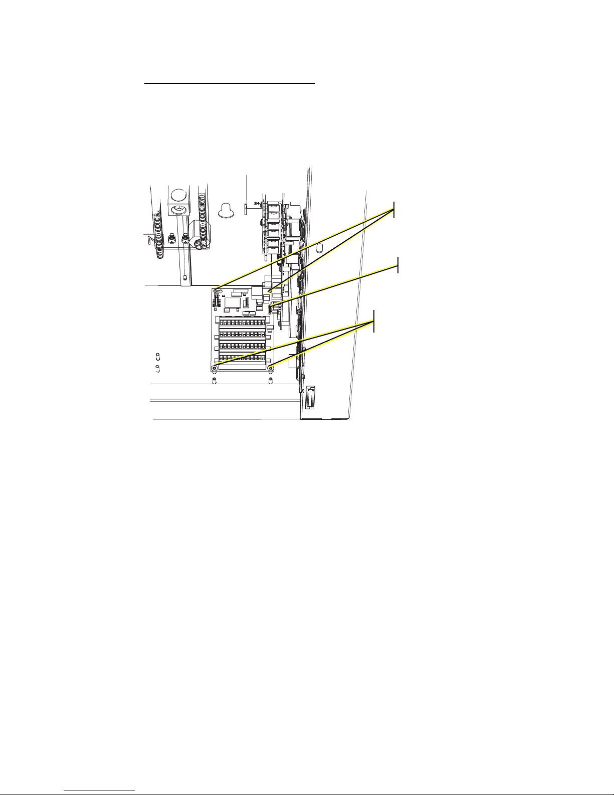
44 Unison® DRd Rack Enclosure Installation Manual
Fluorescent Option Kit
Install the Fluorescent Option Kit
The fluorescent option (DRd-FLO) kit provides 24 outputs for control of 4-wire (0-10 Vdc)
fluorescent ballasts. Each channel output is linked one - to - one with a rack circuit for power
control. The FLO board is comprised of 24 individual 0 - 10 Vdc connections, each rated to
control a maximum of 75 fluorescent ballasts (a maximum of 400mA per channel).
Each output connection is clearly labeled on the removable screw terminal bus connectors.
The removable connectors accept 12 - 24 AWG (4 - .25mm
2
) Class 1 wire.
Step 1: Align the FLO option board to the mounting studs in the bottom of the DRd rack.
• Notice the mounting holes on the FLO option board. One is a slotted
keyhole, another is an open ended slot, and the remaining two on the other
end of the board are standard mounting holes used to secure the board in
place.
Step 2: Set the rear left stud through the slotted keyhole and align the open ended slot
with the back right side mounting stud.
Step 3: Gently slide the FLO board toward the right I/O board aligning the five prong
connector to the receptacle on the I/O board.
Step 4: Secure the remaining two mounting holes to the pems with the screws provided.
Step 2
Step 3
Step 4
Page 49
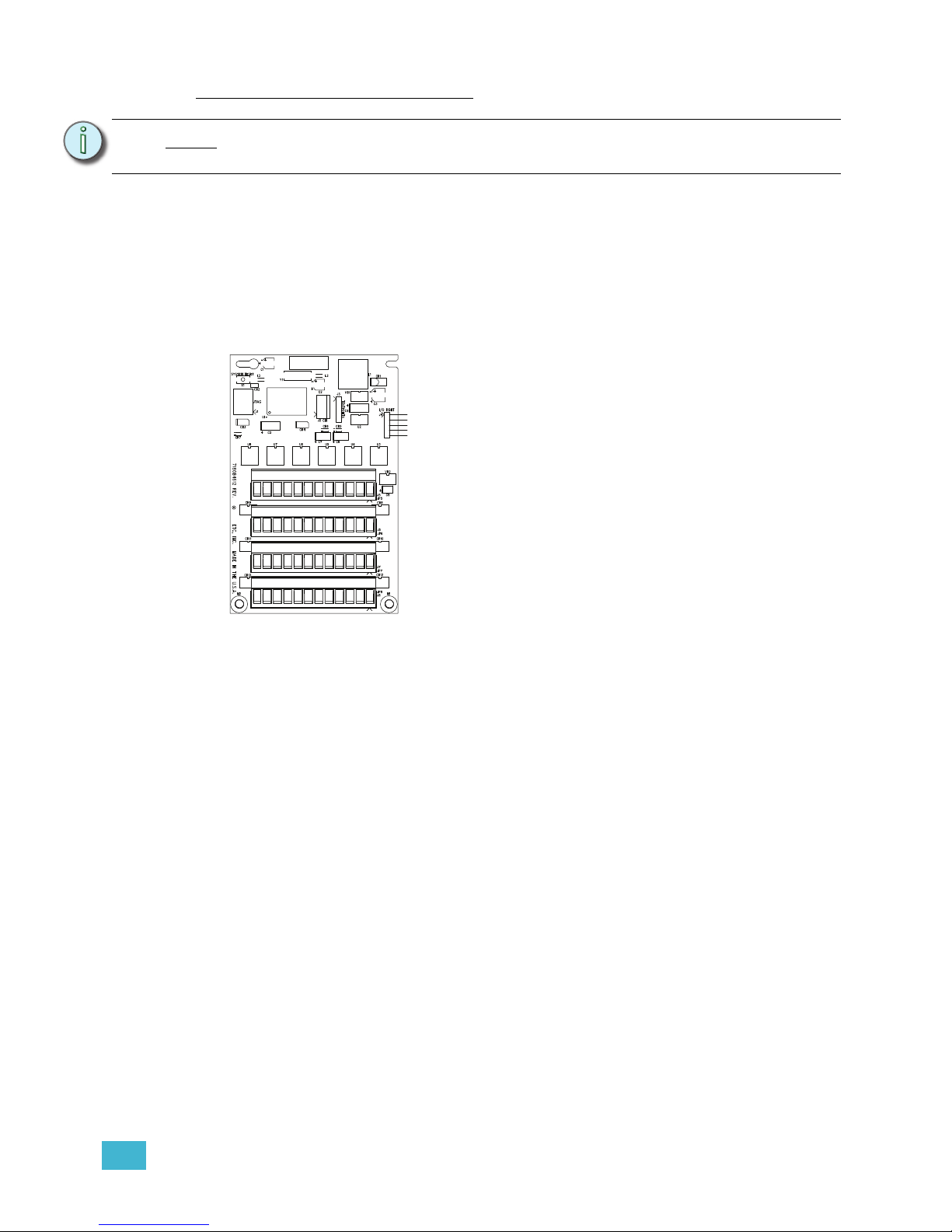
5 Install Rack Options 45
Connect Fluorescent Option Wiring
To control 4-wire fluorescent ballasts, the power circuit in the rack must be a dimmer
module and assigned to 4-wire fluorescent dimmer mode. Reference the related
Architectural Control Processor (SmartLink or Paradigm) configuration manual for
instruction to change dimmer mode.
It is important to label the 4-wire fluorescent load and control wiring sets with the circuit
designation. Control wires terminate on the associated FLO option board output terminal.
Example: If circuit 1 is configured as a dimmer with a 4-wire fluorescent dimmer mode,
ballast control wiring would terminate to the FLO option board output terminals labeled “1”.
Step 1: Pull fluorescent ballast control wiring pairs into the DRd rack enclosure per the
wire entry plan.
Step 2: Strip each wire pair back 1/4 inch (6mm).
Step 3: Remove the bus connector for fluorescent outputs 1-6. The pluggable connector
is seated tight in the receptacle. You may need to gently pry the connector free
from the board using a small 3,35mm or 1/8” flat blade screwdriver.
Step 4: Notice the connector is labeled for your reference during wire termination. Using
a small 3,35mm or 1/8” flat blade screwdriver, loosen the terminals and insert
each of the data ‘+” and data “-” wires in the wire set into the appropriate terminal.
a: Terminate the violet (typical) control wire of the first pair into the “+” terminal
associated to the power circuit.
b: Terminate the gray (typical) control wire of the first pair into the “-” terminal
associated to the power circuit.
c: Tighten each screw terminal until the wire is held snug.
Step 5: Repeat for the remaining fluorescent outputs through output 6.
Step 6: Replace the first bus connector to the FLO option board and repeat for the
remaining fluorescent outputs in the system (up to 24 outputs).
Note:
Fluorescent control wiring must be routed in separate conduit from the line voltage
wiring for 0-10V ballast.
2008
Label
+1- +2- +3- +4- +5- +6-
+7- +8- +9- +10- +11- +12-
+13- +14- +15- +16- +17- +18-
+19- +20- +21- +22- +23- +24-
FLUOR 1 - 6
FLUOR 7 - 12
FLUOR 13 - 18
FLUOR 19 -24
Each of the four bus connectors on the option board
provide termination for six fluorescent outputs. Each
bus connector is labeled for ease of identification and is
pluggable for ease of wiring termination. Terminals
accept 12-24 (4 - .25mm
2
) AWG Class 1 wire.
Page 50
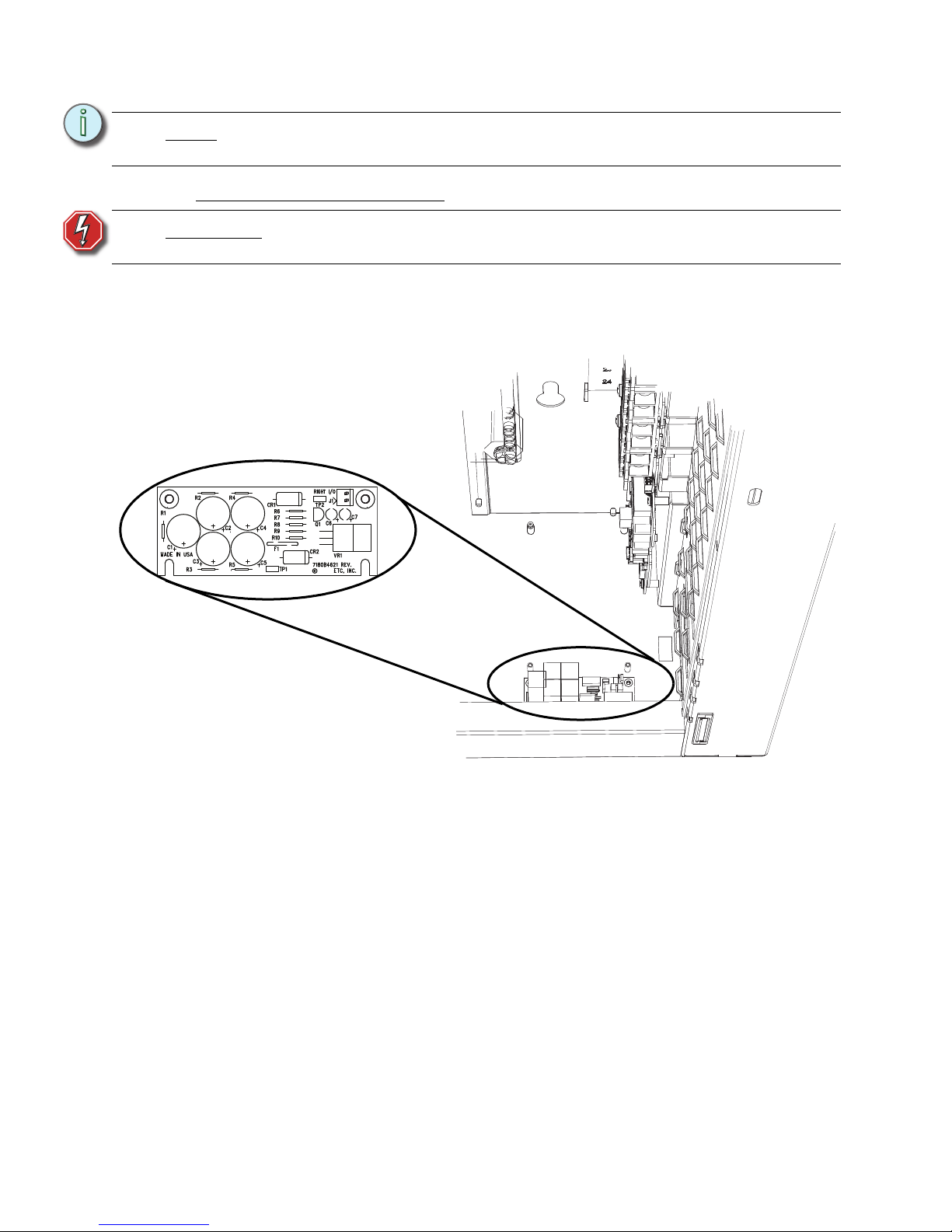
46 Unison® DRd Rack Enclosure Installation Manual
Ride Thru Option Kit
Install the Ride Thru Option Kit
The Ride Thru Option (URTO) kit provides power for the Architectural Control Processor
(either SmartLink ACP or Paradigm ACP) for a minimum of 12 seconds during brief power
outages or power drop outs. The Ride Thru Option board fully charges and is ready for
operation within ten minutes of the DRd rack being powered.
Step 1: Align the Ride Thru Option board to the mounting studs in the bottom of the DRd
rack.
• Notice the mounting holes on the option board. Two are open ended slots
used to place the board, and the remaining two standard mounting holes
used to secure the board in place.
• Align the open ended slots to the studs and rest the other end of the board
on the mounting studs.
Step 2: Secure the board to the two mounting studs with the screws provided.
Note:
A single DRd rack supports the use of either the Unison Ride Thru Option (URTO)
or the Unison Battery Pack Option (UBPO), but not both in the same rack.
WARNING:
Risk of Electric Shock! The Unison ride thru option board retains an
electrical charge even when power to the DRd rack is off.
2008
Page 51
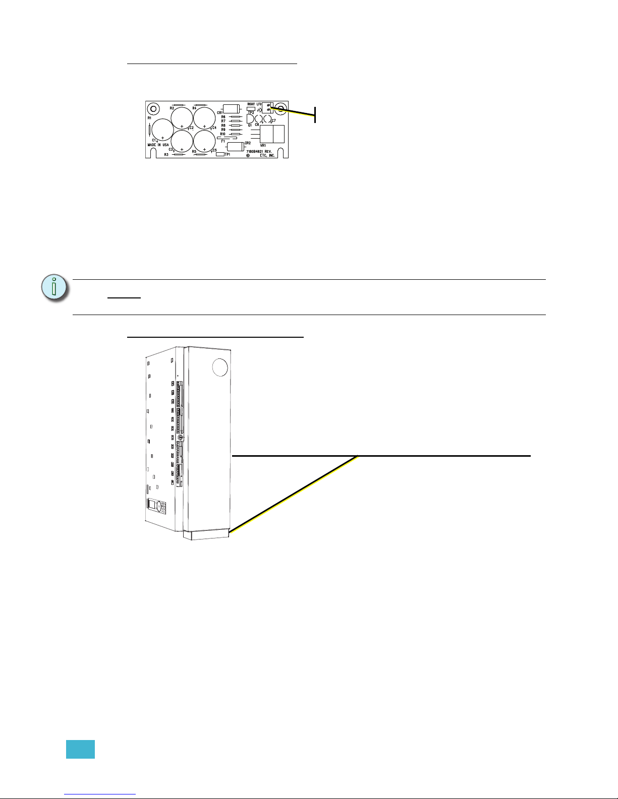
5 Install Rack Options 47
Connect Ride Thru Option Wiring
The Unison Ride Thru Option board is provided with a wiring harness for connection
between the board and the DRd rack right I/O board.
Step 1: Connect one end of the wiring harness to the two pin receptacle on the option
board.
Step 2: Connect the other end of the wiring harness to the two pin receptacle on the DRd
rack right I/O board. See “DRd Right I/O Data Terminations” on page 33.
• Secure the wiring harness to the DRd rack using the cable tie and cable tie
mounts supplied with the Ride Thru Option board.
Battery Pack Option Kit
Install the Battery Pack Option Kit
Step 1: The Battery Pack Option board is provided with a wiring harness for connection
between the battery pack and the right I/O board. Install the wiring harness and
connector into the rack enclosure (the connector is keyed for proper orientation).
Note:
A single DRd rack supports the use of either the Unison Ride Thru Option (URTO)
or the Unison Battery Pack Option (UBPO), but not both in the same rack.
2008
Step 1:
The Battery Pack Option (UBPO) kit provides sustained battery
power to the Architectural Control Processor (either SmartLink
ACP or Paradigm ACP) for up to 90 minutes during power
outages. The self-contained battery installs on the bottom of the
host DRd enclosure.
Page 52
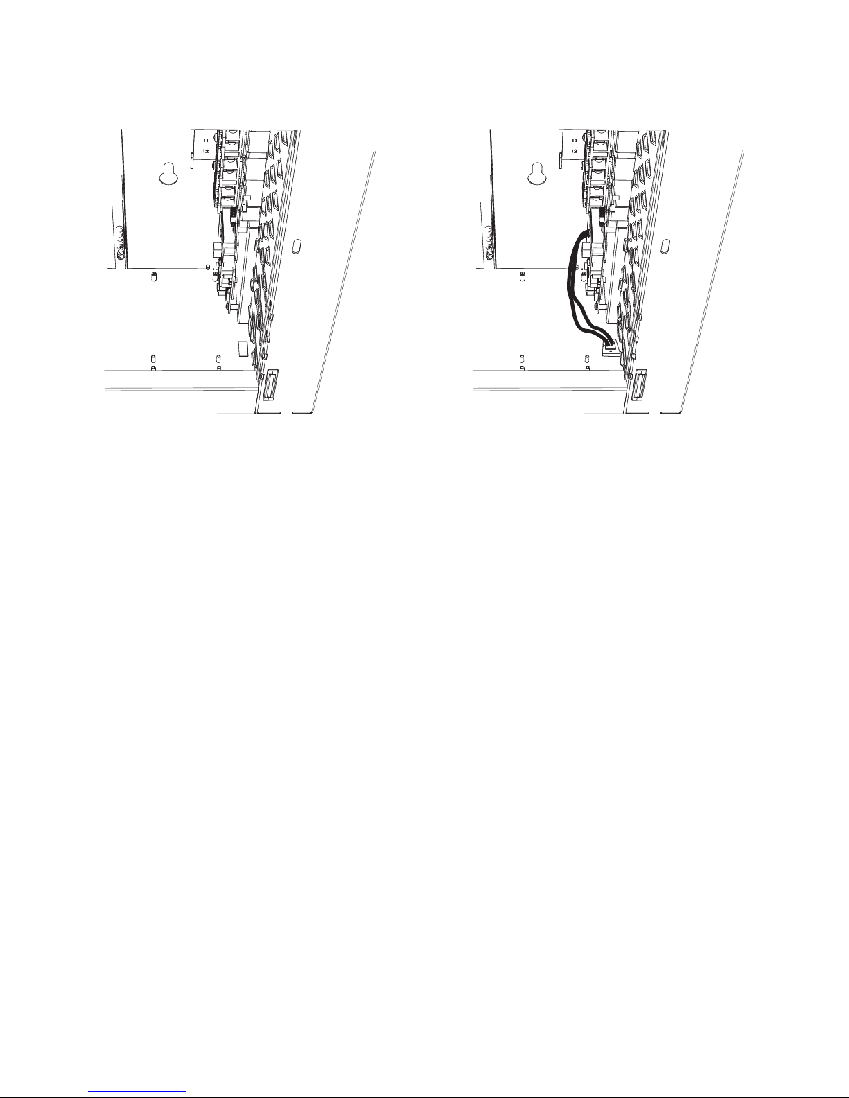
48 Unison® DRd Rack Enclosure Installation Manual
a: Insert the connector end through the opening in the bottom of the DRd rack.
The connector is designed to snap into place without additional hardware,
therefore slight force may be required to ensure the connector installs
properly.
Step 2: Connect the two pin receptacle labeled “Ride Thru/Batt” on the DRd right I/O
board. See “DRd Right I/O Data Terminations” on page 33.
Step 3: Secure the wiring harness to the DRd rack using the cable tie and cable tie mount
supplied with the Battery Pack Option kit. A loose or poorly routed wiring harness
could interfere with option module (DRd-FLO or DRd-DALI) installation.
DRd enclosure before UBPO cable and
connector installation
DRd enclosure after UBPO cable and
connector installation
Page 53
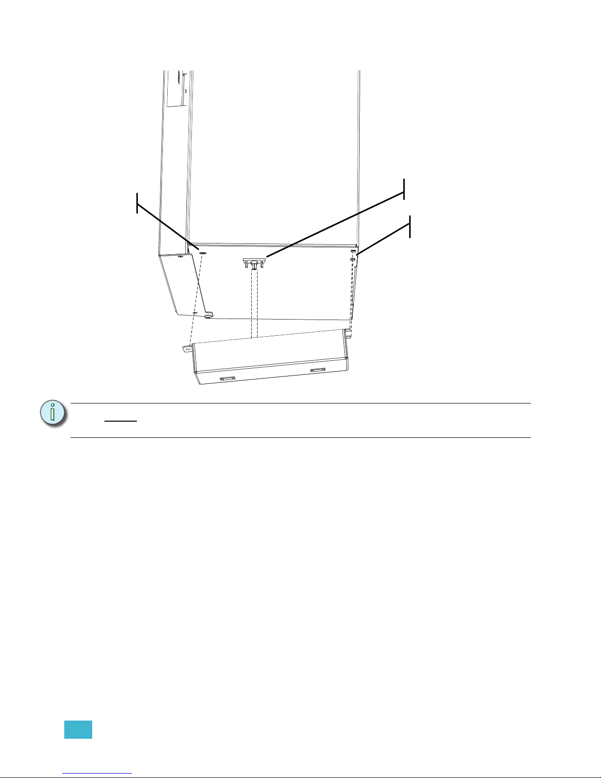
5 Install Rack Options 49
Step 4: Install the battery pack on to the bottom of the rack enclosure.
a: Insert the tabs from the battery pack into the slots in the DRd rack.
b: Secure the battery pack to the DRd rack using the screw provided.
Note:
As the battery is mated to the rack, the connector on the battery pack and the
connector receptacle installed in step 1 also mate.
see Note:
Step 4a:
Step 4b:
Page 54

50 Unison® DRd Rack Enclosure Installation Manual
Chapter 6
Final Installation and Power Up
This chapter contains the following sections:
• Checking the Rack Installation before Installing Modules .51
• Sealing Rack Air Leaks . . . . . . . . . . . . . . . . . . . . . . . . . . . . . .52
• Final Installation. . . . . . . . . . . . . . . . . . . . . . . . . . . . . . . . . . . .53
• Control Bypass (Test Mode) . . . . . . . . . . . . . . . . . . . . . . . . . .54
• Engage Module Retention Bar . . . . . . . . . . . . . . . . . . . . . . . .55
Page 55
6 Final Installation and Power Up 51
Checking the Rack Installation before Installing Modules
It’s a good idea to look over the entire installation before installing modules or applying
power to the rack.
Step 1: Clean out dust, metal scraps or other debris from the rack interior.
• ETC recommends vacuuming the rack interior before installing modules.
Step 2: Check for loose connections, bare wires and damaged insulation.
Step 3: Manually spin the top cooling fan in both directions to be sure it is not obstructed.
Step 4: Correct air leaks caused by misaligned or removed conduit panel openings or
empty screw holes. For complete instructions for this procedure reference
Sealing Rack Air Leaks, page 52.
Step 5: Check resistance between phases, Neutral and Earth for short circuits. With the
power connector to the Power Supply/Dimming Engine still removed from the
rack (this was accomplished prior to installing conduit and terminating any wires,
see Remove the DRd Rack Power Supply/Dimming Engine Access Panel, page
18), and the all modules removed from the rack enclosure, including the Station
Power Module, check resistance between phases, neutral and ground busses
with a digital voltmeter (DVM).
a: Phase to Phase; resistance should be 10M ohm or higher.
b: Phase to Earth (ground); resistance should be 10M ohm or higher.
c: Neutral to Earth (ground); resistance should be less than 1 ohm.
d: Phase to Neutral; resistance should be 10M ohm or higher.
Step 6: Check Load Wiring. Check resistance between the load terminals and the
Neutral buss.
a: Above 1M ohm is normal when no load is connected.
b: Between 6-300 ohm is a reasonable reading when loads are connected.
c: Below 1M ohm indicates a dead short in the load wiring and an infinite
reading indicates no load or an open circuit
.
WARNING:
Power must be turned OFF when you perform this procedure.
Before service, de-energize main feed to dimmer rack and follow
appropriate Lockout/Tagout procedures as described in NFPA Standard
70E. It is important to note that electrical equipment such as dimmer racks
can present an arc flash safety hazard if improperly serviced. This is due to
available large short circuit currents on the feeders of the equipment. Any
work on energized equipment must comply with OSHA Electrical Safe
Working Practices.
CAUTION:
A dead short can cause module damage.
Page 56

52 Unison® DRd Rack Enclosure Installation Manual
Sealing Rack Air Leaks
After you have attached all the conduit to the rack and connected all wiring, you must seal
any air leaks in the rack enclosure that was created during the installation process. ETC
recommends use of urethane aerosol foam to fill air gaps in conduit fittings.
• Seal all conduit access holes.
• Completely cover all conduit openings with fiche paper and/or urethane aerosol foam
or duct seal.
• Seal any air gaps caused by bent access panels.
• Fill in any gaps inside partially filled wiring conduit.
• Fill in other gaps or holes in the cabinet created during installation.
• Any rack enclosures that are installed side - by - side (bolted together) should only have
minimal airflow between them.
CAUTION:
Air leaks can cause dimmer racks to overheat during operation and shut down. Air
leaks can also cause a rack to shut down via an overtemp error, meaning that too
little air is flowing through the front of the rack where it is needed to cool the
dimmers.
Page 57
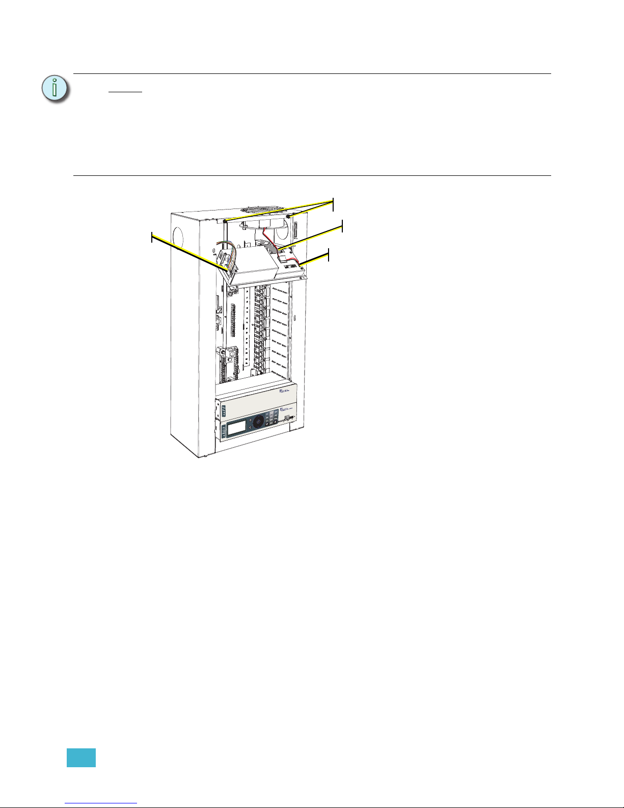
6 Final Installation and Power Up 53
Final Installation
.
Step 2: Reconnect the three cable assemblies to the unit.
a: For the cable bundle on the left side, insert the connector into receptacle until
you hear a click.
b: For the ribbon cable on the right rear side; insert the connector into the
receptacle. Press gently on both sides until it clips into place.
c: For the two-wire cable on the right side, gently press the connector straight
into the receptacle. This connection is also keyed and can only install one
way.
Step 3: Rotate the access panel closed, then slide the panel up approximately one inch
to align the panel to the captured screws.
Step 4: Tighten the two captured screws, securing the access panel in place.
Step 5: Install modules into the rack.
a: Align each dimmer module with the correct module slot and firmly press into
place. The face of the dimmer module should be flush with the DRd rack
enclosure.
b: Install the Station Power Module and Architectural Control Processor into
their respective slots. The Architectural Control Module (either SmartLink
ACP or Paradigm ACP) installs into the lowest module slot. The Station
Power Module installs into the slot directly above the ACP.
Note:
All 230 VAC DRd racks are shipped with a dimmer module retention bar installed.
The dimmer module retention bar prohibits installed modules from being removed
from the rack without the use of a tool.
Before installing modules into the rack, remove this dimmer module retention bar
from the left side of the enclosure (door hinge side). Complete the final installation
procedure outlined below, then Engage Module Retention Bar again. This bar is
required to be installed in all 230 VAC DRd rack enclosures in order to maintain
proper CE rating.
Step 3
Step 2a
Step 2.b
Step 2.c
The rack door
has been
removed from
this graphic for
clarity of this
procedure.
Step 1: Reinstall the Power Supply / Dimming
Engine Access Panel that was
removed prior to conduit installation
and wire termination.
a: Align the guide pins located on the
access panel to the guided slots
on the rack enclosure.
b: Glide the access panel down, so
that it rests fully into the guided
slots.
c: Tilt the supply access panel away
from the rack enclosure.
Page 58

54 Unison® DRd Rack Enclosure Installation Manual
Step 6: Power up the rack. Before installing or removing dimmer or control modules for
service, de-energize main feed to dimmer rack and follow appropriate Lockout/
Tagout procedures as described in NFPA Standard 70E. It is important to note
that electrical equipment such as dimmer racks can present an arc flash safety
hazard if improperly serviced. This is due to available large short circuit currents
on the feeders of the equipment. Any work on energized equipment must comply
with OSHA Electrical Safe Working Practices.
Step 7: Switch all module circuit breakers to the “On” position.
Step 8: Reference the related Architectural Control Processor Programming Guide for
rack configuration setup and operation.
Control Bypass (Test Mode)
Test load circuits connected to the DRd rack enclosure by switching the “Control Bypass”
switch to the “Test” position. The Control Bypass switch allows testing of lighting loads and
provides temporary lighting before complete system commissioning. Return the switch to
its “Normal” setting after the test is complete.
WARNING:
Never power up or operate the Unison DRd rack without all modules
installed. Failure to comply exposes you to dangerously high voltages that
may result in death by electrical shock.
Note:
Store this access panel in a safe place until you are finished roughing in conduit
and terminations. You will need to reinstall this panel when then rack enclosure is
installed and all wires have been terminated.
CAUTION:
Turning the Control Bypass switch to the “Test” position with all module circuit
breakers “On” will bring all lighting loads to full. To select only certain lighting loads
for test, switch “Off” undesired module circuit breakers in the DRd rack enclosure.
Control Bypass switch
Page 59
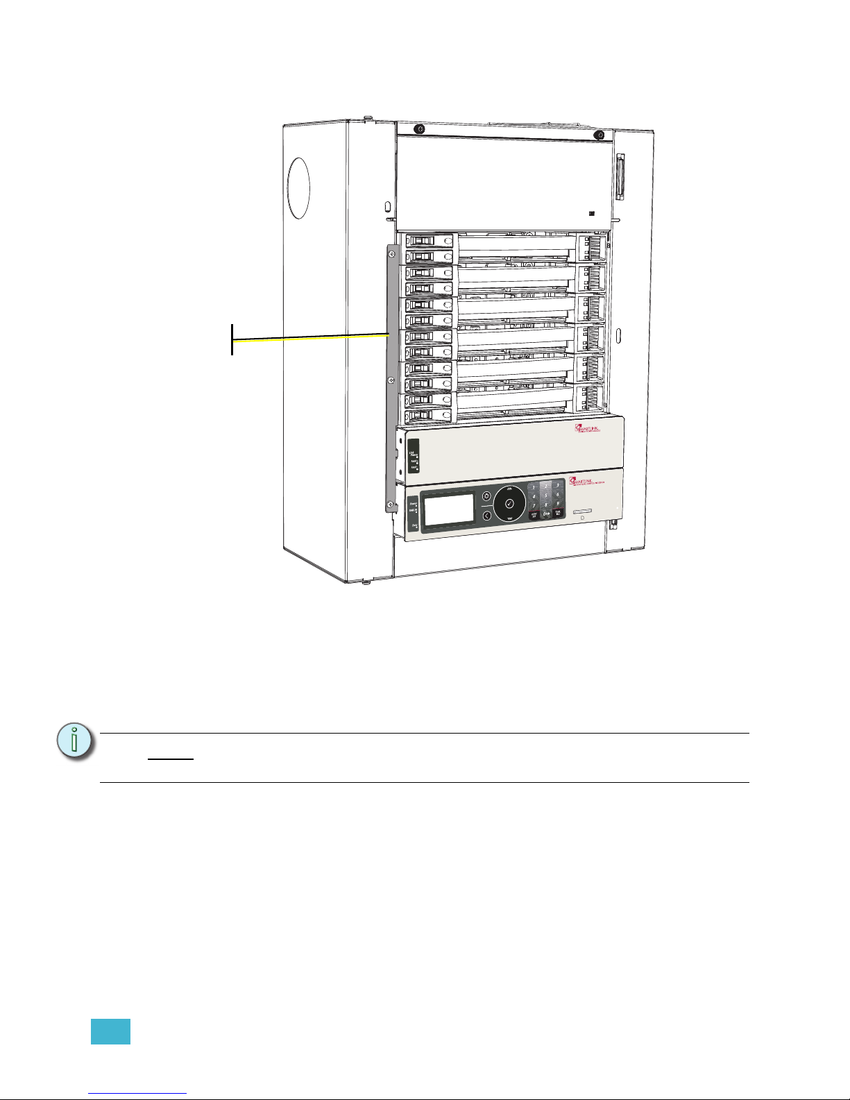
6 Final Installation and Power Up 55
Engage Module Retention Bar
Step 1: Check that all required modules have been installed into the DRd rack enclosure
including dimmer modules, air flow modules, station power module, and Architectural
Control Processor. All module slots should be populated.
Step 2: Loosen the screws on the retention bar.
Step 3: Slide the retention bar to the right. Notice the retention bar has two tabs that insert into
the ACP and station power module slots for retention.
Step 4: Secure the retention bar in place using the screws provided.
Note:
The DRd rack power supply access panel is not accessible when the DRd module
retention kit is installed.
Rack door removed from
graphic only for clarity of
the dimmer module
retention installation.
Dimmer module
retention bar
Page 60
56 Unison® DRd Rack Enclosure Installation Manual
Appendix A
Modules Specification
120 VAC Modules
Module
Type
Description Part Number
Module Weight
(lbs/kg)
AFM Air Flow Module 7083A1072 1.3 lbs / .59 kgs
CC15 Dual 15A Constant Circuit Breaker Module 7083A1021 2.1 lbs / 1.0 kgs
CC20 Dual 20A Constant Circuit Breaker Module 7083A1025 2.2 lbs / 1.0 kgs
D15 Dual 15A, 1.8KW, 350µS Dimmer Module 7083A1018 5 lbs / 2.3 kgs
D15E Dual 15A, 1.8KW, 500µS Dimmer Module 7083A1019 5 lbs / 2.3 kgs
D15F Single 15A, Fluorescent Dimmer Module 7083A1020 2.4 lbs / 1.1 kgs
D20 Dual 20A, 2.4KW, 35OµS Dimmer Module 7083A1022 5 lbs / 2.3 kgs
D20E Dual 20A, 2.4KW, 500µS Dimmer Module 7083A1023 5 lbs / 2.3 kgs
D20F Single 20A, 2.4KW Fluorescent Dimmer Module 7083A1024 2.4 lbs / 1.1 kgs
ELV10 Reverse Phase 10A at 120 VAC, Dimmer Module 7183A1017 2.6 lbs / 1.2 kgs
R15 Dual 15A at 120 VAC Relay Module 7083A1084 2.6 lbs / 1.2 kgs
R20 Dual 20A at 120 VAC, Relay Module 7083A1085 2.6 lbs / 1.2 kgs
230 VAC Modules
AFM Air Flow Module 7183A1050
1.3 lbs / .59
kgs
AFM Air Flow Module 7083A1072 1.3 lbs / .59 kgs
ECC6 Dual 6A, 1.3KW, Constant Circuit Module 7183A1091 2.7 lbs / 1.2 kgs
ECC6N Dual 6A, 1.3KW, Neutral Disconnect Constant Circuit Module 7183A1089 5 lbs / 2.3 kgs
ECC10 Dual 10A, 2.3KW Constant Circuit Module 7183A1092 5 lbs / 2.3 kgs
ECC10N Dual 10A, 2.3KW Neutral Disconnect Constant Circuit Module 7183A1090 5 lbs / 2.3 kgs
ECC15 Dual 15A, 3KW Constant Circuit Module 7070A1046 2.7 lbs / 1.2 kgs
ECC25 Dual 25A, 5KW Constant Circuit Module 7070A1047 2.5 lbs / 1.1 kgs
ED6E Dual 6A, 1.3KW, 400μS Dimmer Module 7183A1085 5 lbs / 2.3 kgs
ED6N Dual 6A, 1.3KW, 400μS Dimmer Module 7070A1081 5.5 lbs / 2.5 kgs
ED6NE Dual 6A, 1.3KW, 400μS Neutral Disconnect Dimmer Module 7183A1079 5 lbs / 2.3 kgs
ED10E Dual 10A, 2.3KW, 400μS Dimmer Module 7083A1086 5 lbs / 2.3 kgs
ED10N Dual 10A, 2.3KW, 400μS Neutral Disconnect Dimmer Module 7070A1082 5.5 lbs / 2.5 kgs
ED10NE Dual 10A, 2.3KW, 400μS Neutral Disconnect Dimmer Module 7070A1080 5.5 lbs / 2.5 kgs
ED15 Dual 15A, 3KW, 225μS Dimmer Module 7083A1035 1.3 lbs / .59 kgs
ED15E Dual 15A, 3KW, 400μS Dimmer Module 7083A1032 5 lbs / 2.3 kgs
ED15N Dual 15A, 3KW, 225μS Neutral Disconnect Dimmer Module 7083A1041 5.6 lbs / 2.5 kgs
ED15NE Dual 15A, 3KW, 400μS Neutral Disconnect Dimmer Module 7083A1042 5.6 lbs / 2.5 kgs
ED15R Dual 15A, 3KW, 225μS RCD Module 7083A1045 5 lbs / 2.3 kgs
ED15RE Single 15A, 3KW, 400μS RCD Module 7083A1046 5 lbs / 2.3 kgs
ED25 Single 25A, 400μS Dimmer Module 7083A1033 5.5 lbs / 2.5 kgs
ED25E Single 25A, 5KW, 600μS Dimmer Module 7083A1034 5.5 lbs / 2.5 kgs
ED25NE Single 25A, 5KW, 600μS, Neutral Disconnect Dimmer Module 7083A1044 5 lbs / 2.3 kgs
Page 61
A Modules Specification 57
ED25N Single 25A, 5KW, 400μS Neutral Disconnect Dimmer Module 7083A1043 5.5 lbs / 2.5 kgs
ED25R Single 25A, 5KW, 400μS RCD Module 7083A1047 5 lbs / 2.3 kgs
ED25RE Single 25A, 5KW, 600μS RCD Module 7083A1048 5 lbs / 2.3 kgs
ER6 Dual 6A, 1.3KW at 230 VAC, Relay Module 7183A1083 5 lbs / 2.3 kgs
ER10 Dual 10A, 2.3KW at 230 VAC, Relay Module 7083A1084 5 lbs / 2.3 kgs
ER15 Dual 15A, 3KW at 230 VAC, Relay Module 7083A1086 3.1 lbs / 1.42 kgs
ER25 Dual 25A, 5KW at 230 VAC, Relay Module 7083A1087 3.1 lbs / 1.42 kgs
240 VAC Modules
Module
Type
Description Part Number
Module Weight
(lbs/kg)
AFM Air Flow Module 7083A1072 1.3 lbs / .59 kgs
HD15 Dual 15A, 3.0KW at 240 VAC, 165µS Dimmer Module 7183A1047 5 lbs / 2.3 kgs
HD15F Single 15A, Fluorescent Dimmer Module 7183A1056 5 lbs / 2.3 kgs
HELV5 Reverse Phase 5A at 240 VAC, Dimmer Module 7183A1055 2.4 lbs / 1.1 kgs
HR15 Dual 15A at 240 VAC, Relay Module 7183A1057 3.1 lbs / 1.42 kgs
HCC15 Dual 15A, Constant Circuit Module 7183A1058 2.6 lbs / 1.2 kgs
277 VAC Modules
Module
Type
Material description Part Number
Module Weight
(lbs/kg)
AFM Air Flow Module 7083A1072 1.3 lbs / .59 kgs
ACC15 Dual 15A at 277 VAC, Constant Circuit Breaker Module 7183A1048 2.7 lbs / 1.2 kgs
ACC20 Dual 20A at 277 VAC, Constant Circuit Breaker Module 7083A1090 2.7 lbs / 1.2 kgs
AD15 Dual 15A, 4.1KW at 277 VAC, Dimmer Module 7083A1006 5 lbs / 2.3 kgs
AD15F Single 15A, 4.1KW at 277 VAC, Dimmer Module 7083A1008 2.4 lbs / 1.1 kgs
AD20 Dual 20A, 5.5KW at 277 VAC, Dimmer Module 7083A1007 5 lbs / 2.3 kgs
AD20F Single 20A, 5.5KW at 277 VAC, Fluorescent Dimmer Module 7083A1009 2.4 lbs / 1.1 kgs
AELV5 Dual 5A at 277 VAC Reverse Phase Dimmer Module 7183A1028 2.6 lbs / 1.2 kgs
AR15 Dual 15A at 277 VAC Relay Module 7083A1082 2.6 lbs / 1.2 kgs
AR20 Dual 20A at 277 VAC Relay Module 7083A1083 2.6 lbs / 1.2 kgs
230 VAC Modules
AFM Air Flow Module 7183A1050
1.3 lbs / .59
kgs
Page 62
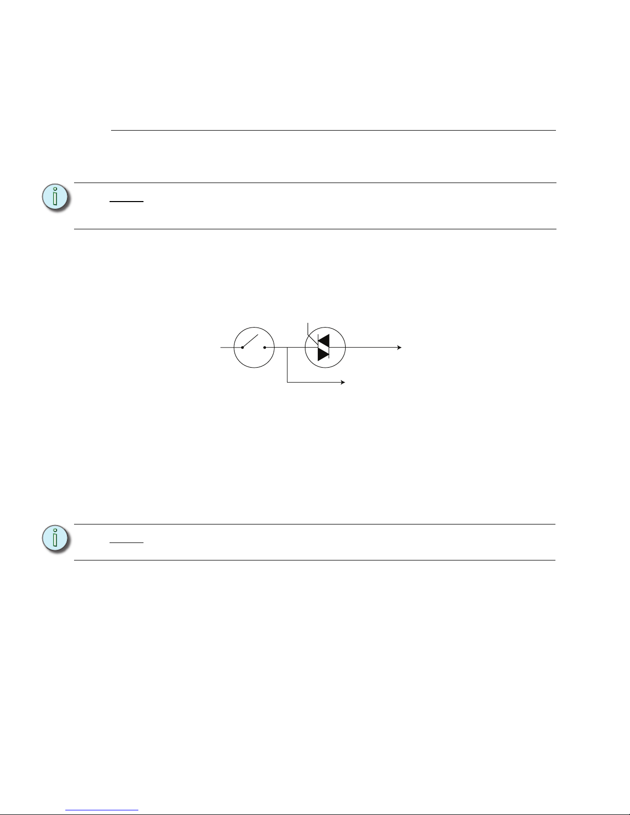
58 Unison® DRd Rack Enclosure Installation Manual
Appendix B
CE 230V Emergency Modules
230V CE Emergency modules are non-standard for Unison DRd 230V Rack. On the
occasion that your installation requires use of these modules, refer to the information
outlined below for installation.
About Emergency Modules
The 230V CE Emergency modules provide two live outputs, one of which is dimmed or
switched, and one of which is live whenever the breaker is turned “On”. This setup allows
the modules to control battery-backed lighting, which requires both a constant and a
switched or dimmed feed.
ETC offers two varieties of Emergency Modules - ED15AFE (15A Dimmer), and
ER15AFE(15A Relay), painted red for easy identification.
Wire Termination
The constant output from the module is connected to the Neutral lugs at the left of the rack.
Therefore, unlike Neutral Disconnect modules, Emergency modules provide a live output
at these lugs, not a neutral connection.
Step 1: Locate the module slot in the rack where the Emergency module is to be fitted.
Step 2: Terminate the outgoing dimmed line to the terminals at the right hand side of the
rack.
Step 3: Terminate the outgoing (constant feed) line to the terminals at the left side of the
rack.
Step 4: Terminate the outgoing (Earth) line to the earth bar terminals.
Note:
When configuring the dimmer modules at the Architectural Control Processor
(SmartLink ACP or Paradigm ACP), configure as either the ED15 or the ER15
module type.
Note:
ETC does not offer a Neutral Disconnect or RCD version of the emergency
modules.
Figure 1: Emergency Module Circuit
Module Circuit Breaker
Dimming Circuit
Dimmed Output
Constant Output
Page 63
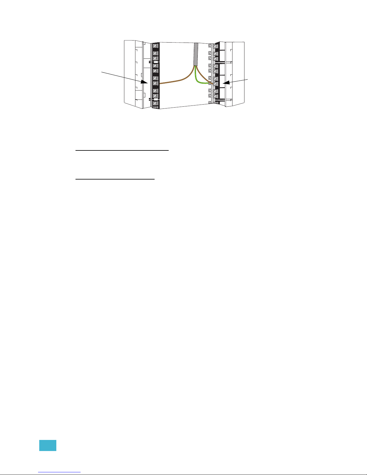
CE 230V Emergency Modules 59
Step 5: Terminate the Neutral as described in the following section, dependant on your
rack type.
Non Neutral Disconnect Racks
For racks which have neutral jumpers fitted, the Neutral of the load, fed by the Emergency
module, should be connected to the Neutral terminal of an adjacent module.
Neutral Disconnect Racks
In racks without neutral jumpers (Neutral Disconnect racks), the Neutral of the load should
not be connected to another load’s Neutral terminal. This can cause unwanted tripping of
RCD modules.
Instead, an auxiliary Neutral terminal must be fitted to the neutral plate and the loads should
be connected to the terminal. If your rack was ordered with Emergency modules from the
factory, the auxiliary neutral terminal will be factory fitted. If you require an auxiliary neutral
terminal for field installation, please contact ETC as shown using the details in Contacting
ETC, page 2.
Figure 2: Emergency Module Connections
Constant live
line is landed
on the Neutral
lugs
Dimmed or
switched line is
landed on live
lugs
Page 64

Corporate Headquarters
3031 Pleasant View Road, P.O. Box 620979, Middleton, Wisconsin 53562-0979 USA Tel +608 831 4116 Fax +608 836 1736
London, UK
Unit 26-28, Victoria Industrial Estate, Victoria Road, London W3 6UU, UK Tel +44 (0)20 8896 1000 Fax +44 (0)20 8896 2000
Rome, IT
Via Pieve Torina, 48, 00156 Rome, Italy Tel +39 (06) 32 111 683 Fax +44 (0) 20 8752 8486
Holzkirchen, DE
Ohmstrasse 3, 83607 Holzkirchen, Germany Tel +49 (80 24) 47 00-0 Fax +49 (80 24) 47 00-3 00
Hong Kong Rm 1801, 18/F, Tower 1 Phase 1, Enterprise Square, 9 Sheung Yuet Road, Kowloon Bay, Kowloon, Hong Kong Tel +852 2799 1220 Fax +852 2799 9325
Service:
(Americas) [email protected]
(UK) [email protected] (DE) [email protected]
(Asia) [email protected]
Web:
www.etcconnect.com
Copyright © 2013 ETC. All Rights Reserved. Product information and specifications subject to change.
7183M2100
Rev C Released 2013-12
 Loading...