

Page 1
ETC Setup Guide
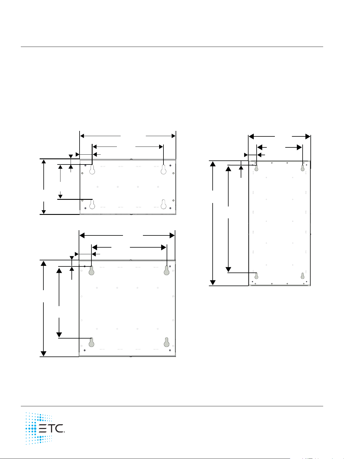
7180A1019
7180A1019-H
356 mm
(14”)
267 mm
(10.5”)
209 mm
(8.23”)
24 mm
(0.95”)
130 mm
(5.12”)
44 mm
(1.75”)
DIN rail Enclosures
Overview
This document covers the installation of the DIN28 - large DIN rail enclosure (ETC Part 7180A1018),
DIN14 - small vertical DIN rail enclosure (ETC Part 7180A1019), DIN14-H - small horizontal DIN rail
enclosure (ETC Part 7180A1019-H), and the DIN8 - mini DIN rail enclosure (ETC Part 7180A1030).
Installation
1: Remove the screws securing the front cover to the enclosure.
2: Use the measurements provided below for specifications to assist with installation.
356 mm
(14”)
267 mm
(10.5”)
7180A1030
203 mm
(8”)
44 mm
(1.75”)
17 mm
(0.67”)
130 mm
(5.11”)
356 mm
(14”)
267 mm
(10.5”)
44 mm
(1.75”)
24 mm
(0.95”)
711 mm
(28”)
622 mm
(24.5”)
7180A1018
3: Secure the DIN rail enclosure to a fire resistant surface, such as drywall, masonry, or concrete, using
four bolts (mounting hardware not provided).
4: Prior to drilling holes in the enclosure for conduit entry, remove electronics (if installed).
5: Drill conduit access following the installation requirements for the DIN-mounted devices.
Corporate Headquarters Middleton, WI, USA +1 608 831 4116 London, UK +44 (0)20 8896 1000
Holzkirchen, DE +49 (80 24) 47 00-0 Rome, IT +39 (06) 32 111 683 Hong Kong +852 2799 1220 Paris, FR +33 1 4243 3535
Web etcconnect.com Support support.etcconnect.com Contact etcconnect.com/contactETC
© 2019 Electronic Theatre Controls, Inc. Trademark and patent info: etcconnect.com/ip
Product information and specifications subject to change. ETC intends this document to be provided in its entirety.
7180M2270 Rev E Released 2019-12
Page 2

ETC Setup Guide
7180A1019-H
7180A1018
7180A1030
DIN rail Enclosures
6: Remove any metal shavings and debris from the enclosure.
7: Install the provided voltage barrier in one of the possible locations in the enclosure. Multiple locations
are provided in the enclosure to meet your installation needs. Use the provided four screws to secure
the barrier in place..
7180A1019
8: Install the DIN rail devices to the DIN rail.
9: Complete the wire terminations and installation procedure for the installed devices as specified in the
device’s installation manual.
10: Reinstall the cover, securing it in place with the previously removed screws.
DIN rail Enclosures Setup Guide Page 2 of 2 ETC
 Loading...