

Page 1
Desire Series by ETC Installation Guide
D40/D60 XTI Wall Mounting
The Wall Mount Bracket accessory for the Desire XTI provides a stable mounting position for the fixture,
while providing a wire way for a clean and functional installation to walls and other vertical surfaces.
WARNING:
WARNING:
● Do not use this fixture with a damaged power lead. If the power lead (cord
● Do not use the fixture with a damaged power lead. If the power lead (cord set) is
set) is damaged, it must be replaced.
damaged, it must be replaced.
● Do not expose the interior of the fixture to moisture. Do not stand in water
● Do not expose the interior of the fixture to moisture. Do not stand in water while
while installing or servicing the fixture.
installing or servicing the fixture.
Failure to follow these warnings can result in serious injury or death.
Failure to follow these warnings can result in serious injury or death.
Keep the following in mind while installing the fixture and Wall Mount.
● The slots on the yoke provide small focusing adjustments.
● The fixture must be attached to the mount and the power and DMX/RDM cords pulled through the
cable grips prior to mounting the assembly on the wall.
● The Wall Mount must be securely attached to the wall directly over the junction boxes or near flush
or surface mounted junction boxes.
● Use an appropriate water-resistant sealant around the junction boxes.
● The fixture and mount assembly is heavy. Take the necessary precautions to ensure your safety.
Installation
WARNING:
To install the Wall Mount:
Step 1: Bolt the fixture to the Wall Mount with the provided three bolts through the holes in the base of the yoke. Use
provided anti-seize on the threaded holes in the wall bracket where the fixture is to mount.
Step 2: Do one of the following. Refer to the illustrations on the next page.
• Route the cables through the cable grips and pull the cables out the back of the mount. Install the provided
watertight hole plugs in the cord grip holes not used.
• Route the cables through the cable grips of flush or surface mounted junction boxes.
Step 3: Leave slack in the cables between the fixture and the cable grip to allow focusing of the fixture.
Step 4: Tighten the cable grips.
Step 5: Make the electrical connection to the supply cable inside the junction box.
Step 6: Attach the Wall Mount and fixture assembly to the wall.
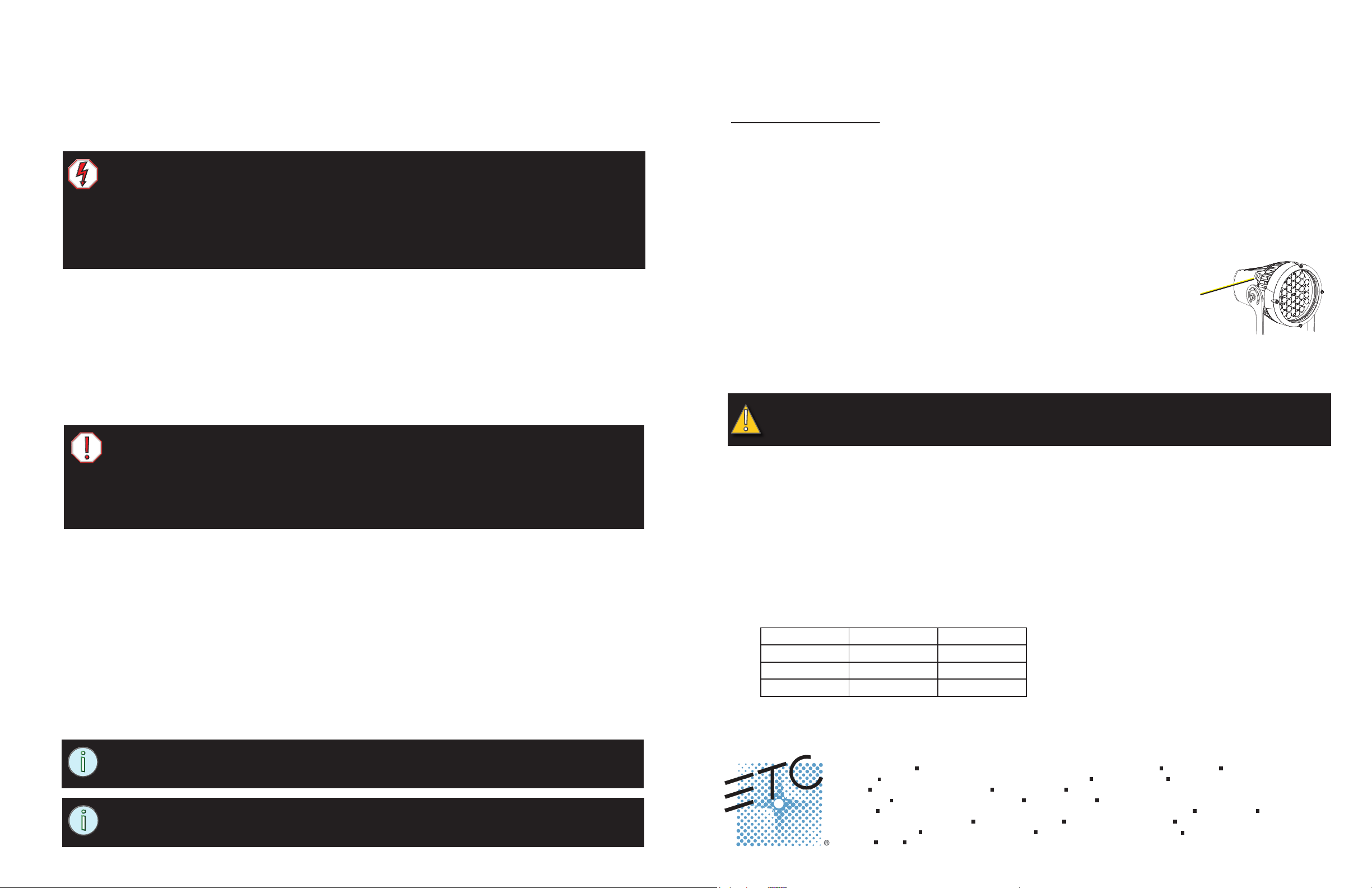
Step 7: Attach a safety cable from the fixture to a secure location on the mounting structure.
Step 8: Make the DMX/RDM connections at the Terminal board.
Step 9: Focus the fixture.
Step 10: Tighten the mounting bolts to secure the fixture to the Wall Mount.
Electrical
CAUTION: The fixtures are sold for 100 to 240VAC universal power input. Verify that the
voltage requirements match the power supply. Connecting the fixture to the wrong voltage
voids the warranty.
● Do not use this fixture if glass lens is deeply scratched or cracked. Damaged lenses
must be replaced.
● Do not mount the fixture on or near combustible surfaces.
Failure to follow these warnings can result in serious injury or death.
Install on a suitable, rigid wall. The installation must meet the published weight and wind-load requirements for the
fixture. Use application appropriate bolts, nuts, and washers such as hot-dipped zinc or stainless steel for wet
locations.
D40XTI
● Weight: 16 pounds, exclusive of accessories and/or color filters and patterns.
● Wind Load: 0.72 cubic feet of effective projected area (EPA).
D60XTI
● Weight: 23 pounds, exclusive of accessories and/or color filters and patterns.
● Wind Load: 0.95 cubic feet of effective projected area (EPA).
Use three bolts to attach the fixture to the Wall Mount. The curved holes in the yoke allow small focusing
adjustments.
Reference D40/D60XTI Installation Instructions for information about electrical requirements and installing the
fixture. The instructions include a yoke template and is available for download at www.etcconnect.com.
NOTE: The EPA number is obtained by estimating Cd (wind drag coefficient) and
multiplying it with the projected ara of the object. Wind drag coefficients were obtained
from AASHTO sixth edition 2013.
NOTE: Reference the Desire XTI User Manual for information for focusing and
configuring the fixture. The User Manual is available for download at
www.etcconnect.com.
Page 1 of 2
● The fixture must be installed by a qualified electrician.
● The fixture must be installed in accordance with national, state, and local electrical codes.
● The fixture must be grounded.
● Application-appropriate electrical junction boxes with cord grips are required.
● The junction boxes must not interfere with focusing.
● The fixture is completely pre-wired at the factory and there is no need for entry into the housing.
● The fixture must be connected to a non-dimmable power source in order to avoid damage to its internal
power supply and other electrical components. Dimming will damage the fixture and void the warranty.
Power Requirements
● Acceptable voltage is rated 100 to 240VAC 50/60 Hz universal power input.
Mains Europe North America
Line Brown Black
Neutral Blue White
Ground Green/Yellow Green
Corporate Headquarters
London, UK
Rome, IT
Holzkirchen, DE
Hong Kong
Service:
Web:
7410M2150
Unit 26-28, Victoria Industrial Estate, Victoria Road, London W3 6UU, UK Tel +44 (0)20 8896 1000 Fax +44 (0)20 8896 2000
Via Pieve Torina, 48, 00156 Rome, Italy Tel +39 (06) 32 111 683 Fax +44 (0) 20 8752 8486
(Americas) service@etcconnect.com (UK) service@etceurope.com (DE) techserv-hoki@etcconnect.com (Asia) service@etcasia.com
www.etcconnect.com
3031 Pleasant View Road, P.O. Box 620979, Middleton, Wisconsin 53562-0979 USA Tel +608 831 4116 Fax +608 836 1736
Ohmstrasse 3, 83607 Holzkirchen, Germany Tel +49 (80 24) 47 00-0 Fax +49 (80 24) 47 00-3 00
Rm 1801, 18/F, Tower 1 Phase 1, Enterprise Square, 9 Sheung Yuet Road, Kowloon Bay, Kowloon, Hong Kong Tel +852 2799 1220 Fax +852 2799 9325
Rev B Released 2014-02
Copyright © 2014 ETC. All Rights Reserved. Product information and specifications subject to change.
ETC intends this document to be provided in its entirety.
Page 2
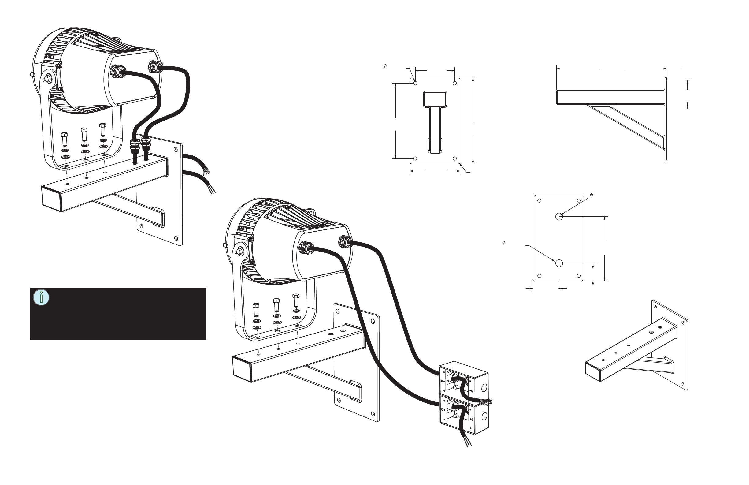
Wall Mount Covering
Junction Boxes
Wall Mount Dimensions
To junction boxes
in wall
.500 inch
(12.7mm)
10.5 inch
(267mm)
5.50 inch
(140mm)
7.00 inch
(178mm)
12.00
inch
R.25 inch
(6.35mm)
1.00 inch
(25.4mm)
15.37
inch
4.00 inch
(102mm)
1.00 inch
(25.4mm)
9.00 inch
(229mm)
NOTE: The safety cable must be securely
attached to both the fixture housing and the
mounting structure. Take care to leave as
little slack as possible in the safety cable to
avoid the cable catching on the yoke of the
fixture.
Wall Mount With Exposed
Junction Boxes
2.50 inch
(64mm)
3.50 inch
(89mm)
DMX/RDM
Power
Flush or surface mount
junction boxes
Page 2 of 2
 Loading...