

Page 1
ETC Installation Guide
DMX Emergency Bypass Controller
Overview
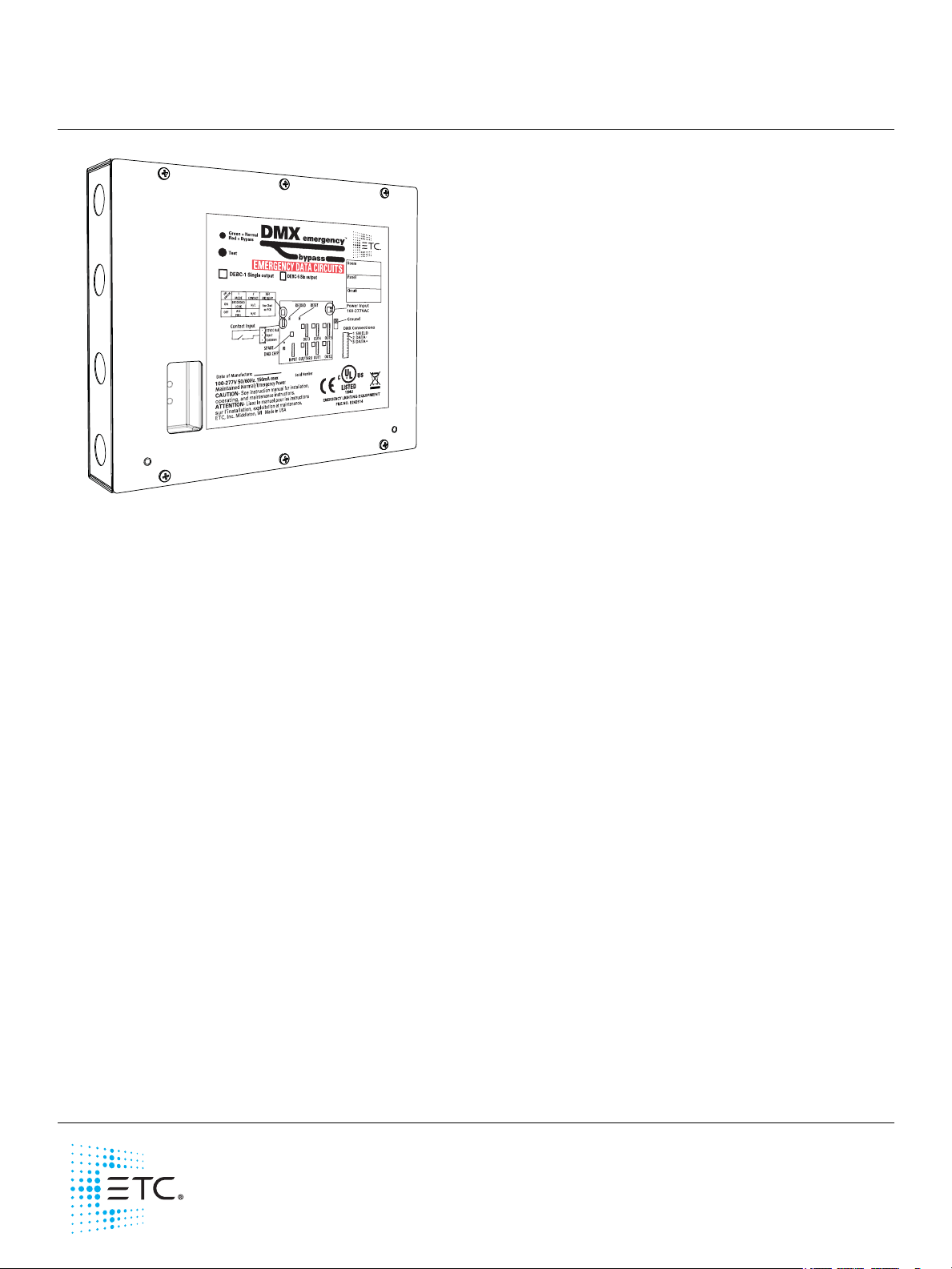
The DMX Emergency Bypass Controller (DEBC) allows
DMX512-controlled fixtures, such as LEDs, to operate as
normal/emergency fixtures by bypassing a single universe of
DMX512 directly to the connected fixtures. This unit is
designed to override the control signals on designated
emergency lighting fixtures that are separately energized
upon loss of utility power.
The bypass is triggered through the onboard contact closure
input, such as in the event of a power outage. The contact
closure may be normally open or normally closed, and is
supplied by an external device. For example, to turn lights on
during a power loss, utilize the ETC Emergency Bypass
Detection Kit (EBDK) or other suitable power sensing device.
The DEBC may also operate as part of a closed-loop fire alarm
system.
The DEBC requires that the electrical supply to the lighting fixtures is a normal/emergency source fed by an
upstream transfer switch or other emergency power system. Upon loss of utility power or other event when
egress lighting is needed, a dry contact closure or +12VDC input forces the DMX data link that is feeding
connected fixtures into a bypass state. The bypass state can be defined as “All DMX channels to full” or a
designated emergency setting of each DMX channel to a selected level.
DEBC Types
There are two types of DMX Emergency Bypass Controllers available:
• Single-output DEBC (DEBC-1): Single DMX input, single DMX output
• Six-output DEBC (DEBC-6): Single DMX input, six DMX outputs
Important Safeguards
When using electrical equipment, basic safety precautions should
always be followed including the following:
–READ AND FOLLOW ALL SAFETY INSTRUCTIONS.
–Do not use this equipment for other than its intended use.
–SAVE THESE INSTRUCTIONS.
–All servicing should be performed by qualified personnel only.
Product Specification
• UL924 listed for use in emergency lighting systems
• Compatible with PLASA DMX512 protocol
• Compatible with 100–277VAC/50–60Hz emergency power (hot, neutral, and ground)
• Panic input can accommodate a maintained normally open (NO) dry contact, normally closed (NC) dry
contact, or +12VDC signal
Corporate Headquarters Middleton, WI, USA Tel +608 831 4116 Service: (Americas) service@etcconnect.com
London, UK
Rome, IT
Holzkirchen, DE
Hong Kong
Web: etcconnect.com
Product information and specifications subject to change. ETC intends this document to be provided in its entirety.
7180M2190
Tel +44 (0)20 8896 1000 Service: (UK) service@etceurope.com
Tel +39 (06) 32 111 683 Service: (UK) service@etceurope.com
Tel +49 (80 24) 47 00-0 Service: (DE) techserv-hoki@etcconnect.com
Tel +852 2799 1220 Service: (Asia) service@etcasia.com
© 2017 Electronic Theatre Controls, Inc.
Rev B Released 2017-05
Page 2
ETC Installation Guide
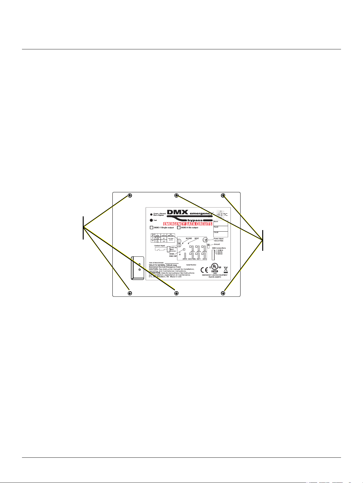
Remove these
screws to remove
cover
Remove these
screws to remove
cover
DMX Emergency Bypass Controller
Installation
Install the DEBC enclosure on a suitable surface, within 1,640 ft (500 m) of the Emergency Bypass
Detection Kit (EBDK) or other suitable power sensing or triggering device providing a contact closure
output.
Required Installation Tools and Supplies
• Small 3 mm or 1/8” flat-blade screwdriver (jeweler’s screwdriver) for wire terminations
• #2 Phillips screwdriver for the front cover
• Four mounting bolts or screws suitable to hold up to 6 lb (2.7 kg)
Install the DEBC
1: Remove the front cover from the DMX Emergency Bypass Controller, revealing access to the
mounting keyholes.
a: Remove the six screws securing the front cover to the unit.
b: Lift the cover from the unit.
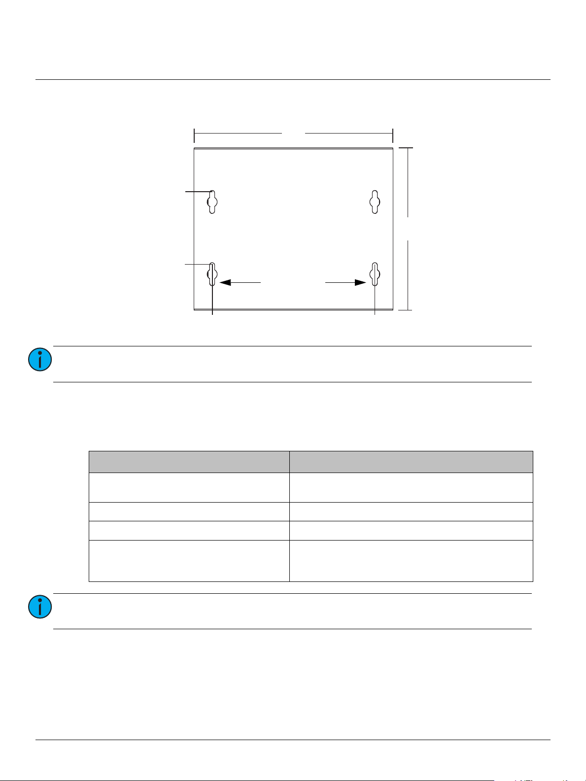
2: Use the measurements provided in the image that follows for mounting bolt locations.
3: Secure the DEBC enclosure to the wall using four bolts (mounting hardware not provided).
DMX Emergency Bypass Controller Installation Guide Page 2 of 8 ETC
Page 3
ETC Installation Guide
1 in
(25.4 mm)
6.5 in
(165 mm)
2.5 in
(63 mm)
10 in
(254 mm)
11 in
(280 mm)
9 in
(229 mm)
Secure with a
screw in either
bottom slot
DMX Emergency Bypass Controller
4: To further secure the box to the wall, use a single screw (also not provided) in either bottom slot (see
image below).
Note:
Install the DEBC enclosure on a suitable surface, within 1,640 ft (500 m) of the
Emergency Bypass Detection Kit (EBDK) or suitable triggering device.
Route Conduit and Wiring
Four conduit knockouts are provided on each side of the enclosure for installation convenience. Emergency
or normal/emergency AC power will utilize the two topmost knockouts while the remaining knockouts
near the bottom of each side will accommodate the Class 2 wiring (DMX and panic input wire).
Termination type Specified wire type
AC input (emergency or normal/emergency)
2 wires (hot, neutral)
Ground
Panic input
DMX in/out
Note:
Power and control wires must be run in separate conduits. Follow all local code
restrictions.
24–10AWG / .2mm
Ground lug accepts 14–2AWG / 2.5mm
30–12AWG / .05mm
Belden 9729 (or approved equivalent for DMX, such as
CAT5 or CAT5E with insulation displacement
connectors)
2
–4mm
2
–2.5mm
2
2
–35mm
2
2
DMX Emergency Bypass Controller Installation Guide Page 3 of 8 ETC
Page 4
ETC Installation Guide
CONFIG
1234
RECORD
PANIC IN
V OUT
INPUT
COM
ON
OFF
DMX Emergency Bypass Controller
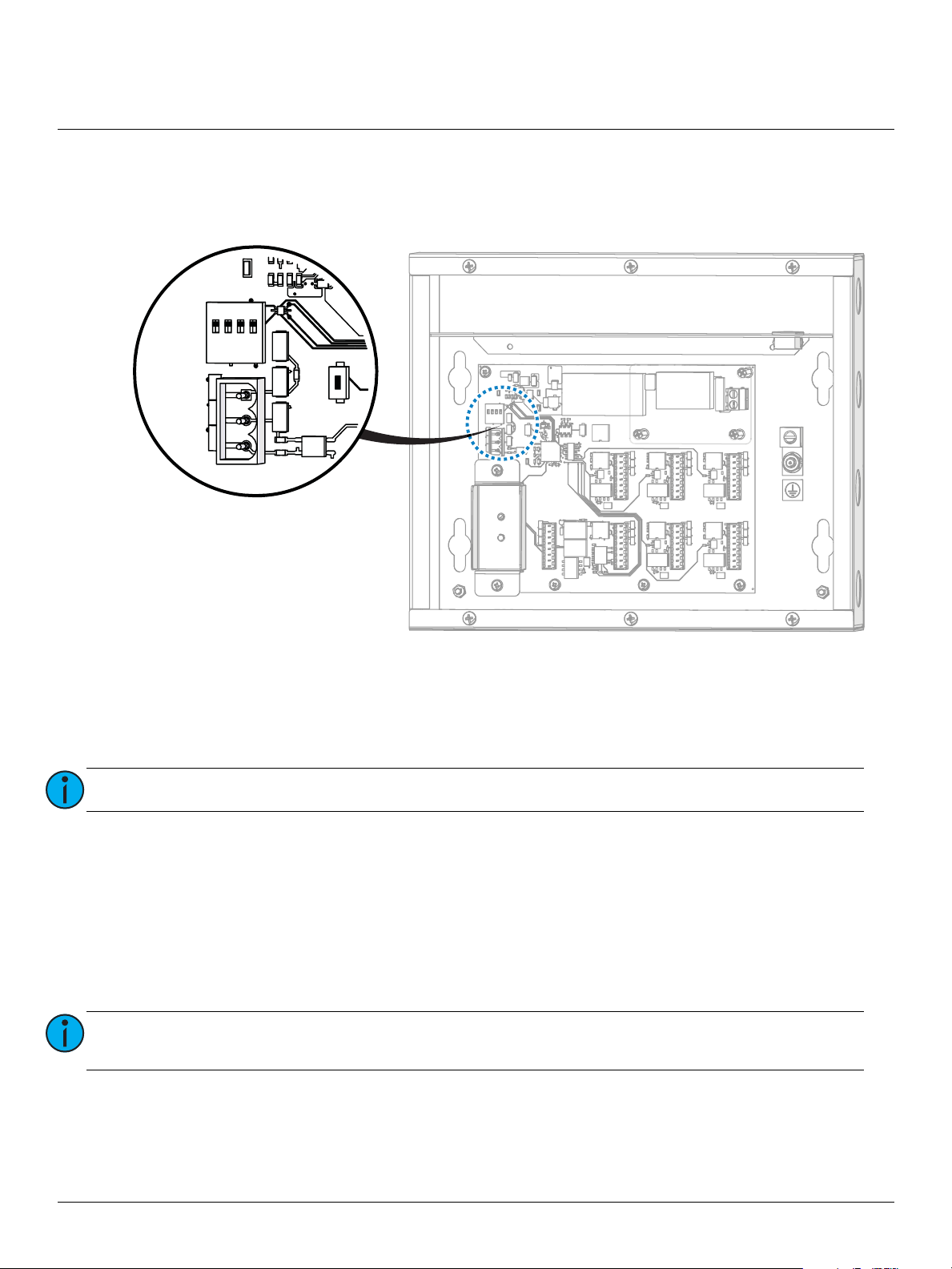
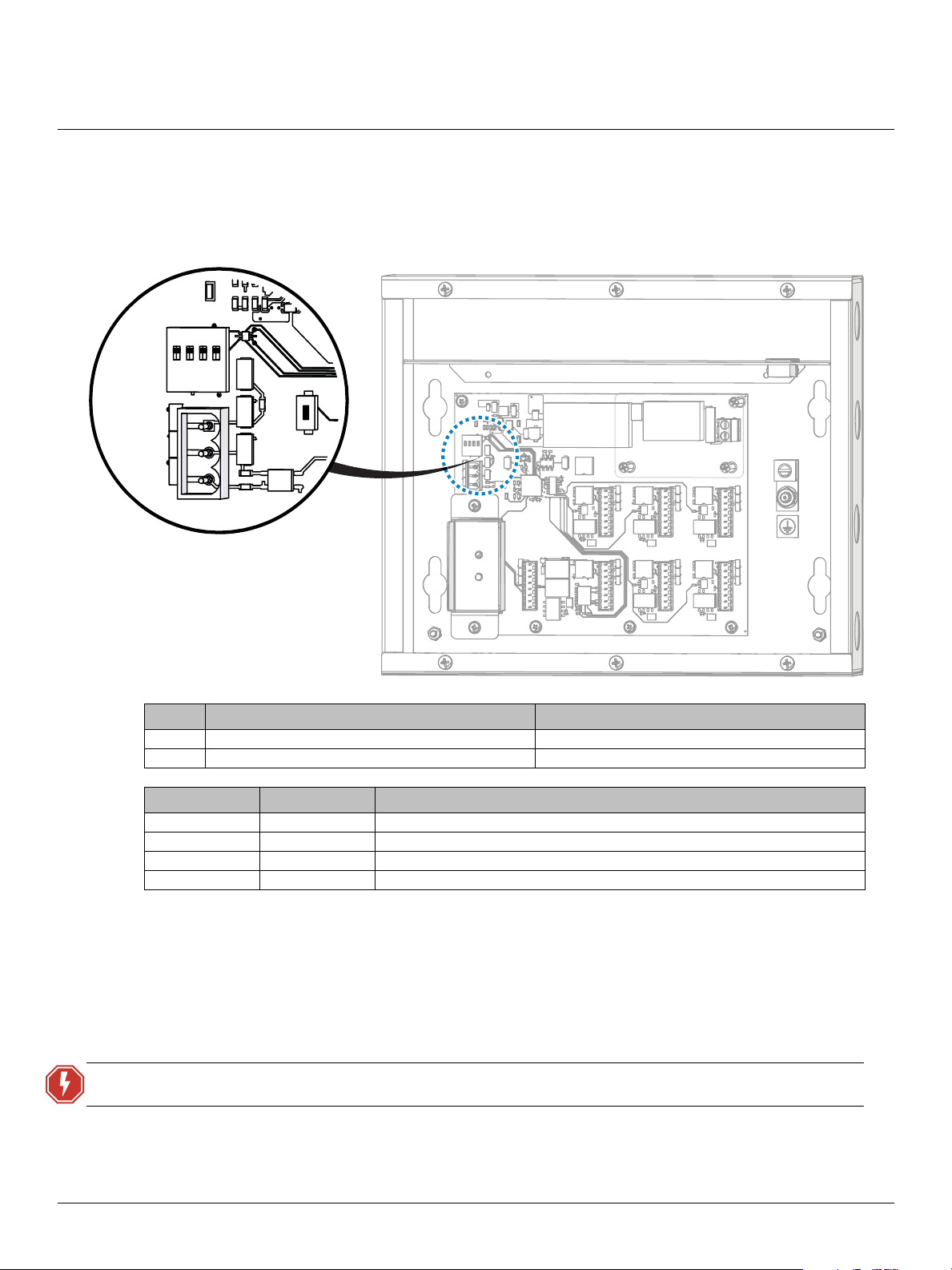
Connect Panic Input
The panic input can be configured as a maintained dry contact or a +12VDC signal. Determine which
configuration is best for your application and wire the receptacle on J4 of the control board accordingly.
Maintained Dry Contact
1: Strip 1/4” (6 mm) insulation from the two panic wires.
2: Locate and remove the PANIC IN connector from J4 on the control board.
3: Loosen the V OUT terminal and the INPUT terminal.
Note:
4: Insert the first panic input wire into the V OUT terminal. Using the jeweler’s screwdriver, tighten the
screw firmly onto the wire.
5: Insert the second panic input wire into the INPUT terminal. Using the jeweler’s screwdriver, tighten
the screw firmly onto the wire.
The V OUT terminal can also be identified by the triangle that points to pin 1.
+12VDC Signal
1: Strip 1/4” (6 mm) insulation from the two panic wires.
2: Locate and remove the PANIC IN connector from J4 on the control board.
Note:
3: Loosen the INPUT terminal and the COM terminal.
4: Insert the +12VDC wire into the INPUT terminal. Using the jeweler’s screwdriver, tighten the screw
firmly onto the wire.
5: Insert the common wire into the COM terminal. Using the jeweler’s screwdriver, tighten the screw
firmly onto the wire.
Identify the panic wires coming from the sensing device and determine which one is
+12VDC and which one is common.
DMX Emergency Bypass Controller Installation Guide Page 4 of 8 ETC
Page 5
ETC Installation Guide
DMX IN
DMX OUT/THRU
Single-output
DMX connections
DMX IN
DMX OUT/THRU
DMX OUT1
DMX OUT2
DMX OUT3
DMX OUT4
DMX OUT5
Six-output DMX connections
DMX Emergency Bypass Controller
Connect DMX In/Out
Note:
A DMX Cable Preparation Kit with Screw Connector (part number 4100A1012) for use
with Belden 9729 cable (or equivalent) is provided with the DMX Emergency Bypass
Controller. Before you connect the DMX IN and DMX OUT, please follow the instructions
in that kit to prepare the cable.
ETC offers a DMX Cable Preparation Kit with IDC Connector (part number 4100A1013)
for use with installations utilizing Category 5 cable (or equivalent, such as 5e or 6).
Contact ETC Professional Services to order this cable preparation kit, if required.
Note:
The six-output DMX Emergency Bypass Controller has one DMX OUT/THRU output (J9)
and five optically isolated DMX outputs. RDM is passed through the device to the DMX
OUT/THRU connection only; the other outputs transmit DMX but do not provide RDM
functionality.
When the DMX Emergency Bypass Controller is unpowered, DMX data will pass to the
DMX OUT/THRU output only.
1: Locate the DMX cable that is coming “in” from the DMX source: this is DMX IN. Label the cable.
2: Locate the DMX cable (or cables) going “out” to the DMX controlled fixtures, and label the cables.
3: Prepare and terminate each of the cables to the appropriate connectors for the cable type:
• Belden 9729 cable (or equivalent) and screw terminal style connectors: Follow the cable
preparation instructions as provided with the DMX Cable Preparation Kit with Screw Connector
for Belden 9729 cable (part number 4100A1012).
• Category 5 cable (Belden 1583A or equivalent) and insulation
displacement (IDC) connectors: Follow cable preparation
instructions as provided with the DMX Cable Preparation Kit for
Category 5 cable (part number 4100A1013).
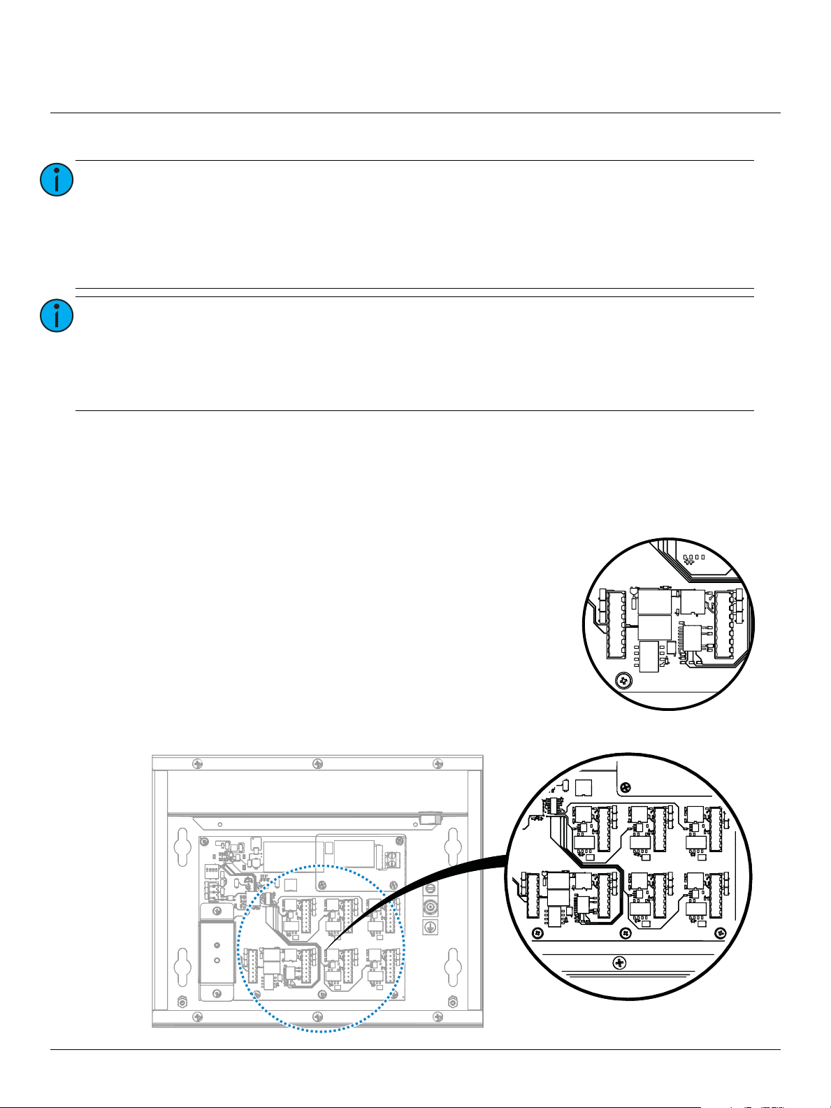
4: Install the connectors to the appropriate receptacles on the control
board. DMX IN installs to J8, and the other connections are as
follows:
• Single-output DEBC: DMX OUT/THRU to J9 (see image at right)
• Six-output DEBC: DMX OUT/THRU to J9, and DMX OUT to J10,
J11, J5, J6, and J7 (see image below)
DMX Emergency Bypass Controller Installation Guide Page 5 of 8 ETC
Page 6
ETC Installation Guide
AC INPUT
L
N
Ground
Lug
DMX Emergency Bypass Controller
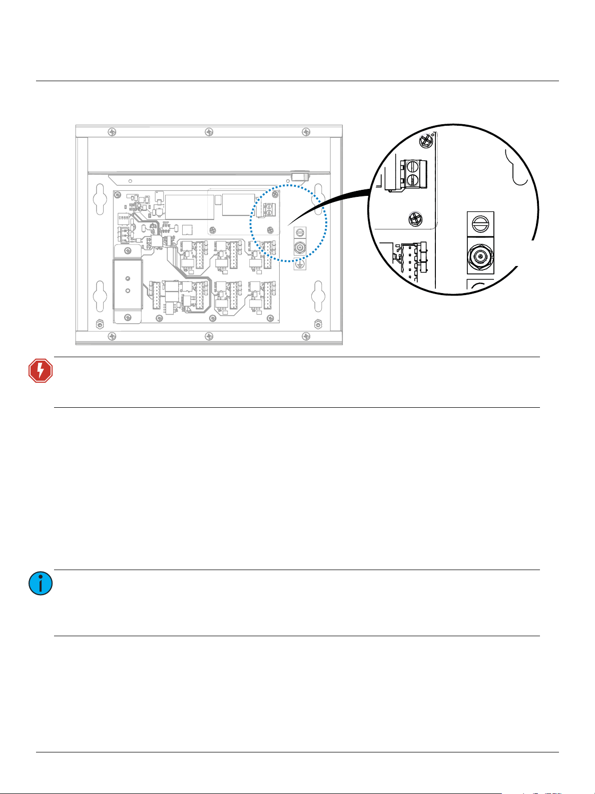
Connect AC and Ground Input
WARNING:
1: Strip 1/2” (13 mm) of insulation from the hot, neutral, and ground wires.
2: Locate and loosen the earth ground lug located on the right side of the control board, near the AC
INPUT connector.
3: Locate the earth ground wire (typically green or green with a yellow stripe) and insert it into the
ground lug; tighten the lug firmly onto the wire.
4: Locate the two-pin connector located at J1 on the control board; using the jeweler’s screwdriver,
loosen both terminals.
5: Locate the hot wire (typically black) and insert it into pin 1, labeled “L” on the AC INPUT terminal;
tighten the terminal firmly onto the wire.
6: Locate the neutral wire (typically white) and insert it into pin 2, labeled “N” on the AC INPUT
terminal; tighten the terminal firmly onto the wire.
Note:
Risk of electric shock! Before terminating the AC power wiring, verify that the
main breaker is in the off position and follow the proper lockout/tagout
procedures per NFPA Standard 70E.
In order for the system to function correctly in an emergency state, the DMX Emergency
Bypass Controller must be powered via a normal/emergency supply provided by an
upstream transfer device such as the ETC SC1008 BCELTS or ELTS2. If the DMX
Emergency Bypass Controller is powered from an emergency supply only, DMX will be
available only on the DMX OUT/THRU connector when power is absent.
DMX Emergency Bypass Controller Installation Guide Page 6 of 8 ETC
Page 7
ETC Installation Guide
CONFIG
1234
RECORD
PANIC IN
V OUT
INPUT
COM
ON
OFF
DMX Emergency Bypass Controller
Configure
Set the configuration for the DMX bypass operation at the CONFIG DIP switches, located at S1 on the
control board. By default, all four DIP switches are in the OFF position. See the table below to set the
function of the DMX bypass.
Power Up
Switch 1: Mode Switch 2: Panic Input
OFF Panic look sets all 512 channels to full Normally Open (NO) maintained panic input
ON Panic look is recordable (snapshot) Normally Closed (NC) maintained panic input
Switch 3 Switch 4 Panic Exit Delay
OFF OFF Deactivates panic look immediately when panic input is released.
OFF ON Deactivates panic look 10 seconds after panic input is released.
ON OFF Deactivates panic look 30 seconds after panic input is released.
ON ON Deactivates panic look 10 minutes after panic input is released.
1: Verify that incoming power to connected normal/emergency lighting fixtures is wired to an
emergency lighting transfer device, such as the ETC SC1008 Branch Circuit Emergency Lighting
Transfer Switch (BCELTS) or Emergency Lighting Transfer System (ELTS2).
2: Replace the cover on the DMX Emergency Bypass Controller. Be careful not to damage the Test
button and the Normal/Bypass indicator while replacing the cover.
WARNING:
3: Restore power to the main breaker that supplies power to the controller. See
Testing
Replace the cover on the DEBC before applying power to avoid electric shock!
Operational Notes and
for details of how the DMX Emergency Bypass Controller should respond when powered.
DMX Emergency Bypass Controller Installation Guide Page 7 of 8 ETC
Page 8

ETC Installation Guide
CONFIG
1234
RECORD
PANIC IN
V OUT
INPUT
COM
ON
OFF
DMX Emergency Bypass Controller
Operational Notes and Testing
Verify that the external power sensing or triggering device is working properly. This could be the ETC
Emergency Bypass Detection kit (EBDK) or a fire alarm system.
What to Expect in Normal DMX Mode
If the DMX Emergency Bypass Controller is powered from a normal/emergency power source, the DEBC’s
Normal/Bypass LED indicator (located on the front of the unit) will illuminate green.
What to Expect in DMX Bypass Mode (loss of normal power)
• The DEBC Normal/Bypass LED indicator will illuminate red when an emergency state (panic input) is
triggered.
• The DMX panic look that was preset using the CONFIG DIP switches will output to the lighting fixtures
attached to the DEBC.
Recording a Panic Look from an External DMX512 Source
1: Set the CONFIG DIP switch 1 in the ON (up) position.
2: Verify that the external DMX source is outputting DMX
to the normal/emergency lighting fixtures through the
DEBC.
3: Hold down the RECORD button, located at S2 on the
control board, for approximately 5 seconds.
The Status LED, located below the RECORD button, will
flash rapidly while you hold the RECORD button, and
then will illuminate solid on when recording is complete
(if DMX is received by the DEBC).
Note:
If the DMX source is unplugged or DMX is interrupted from the DEBC during recording,
the Status LED will instead turn off at the end of recording. This indicates that the panic
look was not recorded.
Periodic Testing Procedure
Pressing and holding the Test button (located on the front panel of the DEBC) forces the unit to output its
panic look. This is true as long as it is receiving power, regardless of the PANIC IN closure/signal state. Once
you release the Test button, the DEBC will stop bypassing incoming DMX and return to the normal state
after two seconds.
The Panic Exit Delay timer settings (set using DIP switches 3 and 4) have no effect on the DEBC when you
release the Test button. See
DMX Emergency Bypass Controller Installation Guide Page 8 of 8 ETC
Configure
on
page 7
.
 Loading...