

Page 1
ETC Installation Guide
CueSystem CueSpider Series Outstations
Corporate Headquarters Middleton, WI, USA Tel +608 831 4116 Service: (Americas) service@etcconnect.com
London, UK
Tel +44 (0)20 8896 1000 Service: (UK) service@etceurope.com
Rome, IT
Tel +39 (06) 32 111 683 Service: (UK) service@etceurope.com
Holzkirchen, DE
Tel +49 (80 24) 47 00-0 Service: (DE) techserv-hoki@etcconnect.com
Hong Kong
Tel +852 2799 1220 Service: (Asia) service@etcasia.com
Web: etcconnect.com
© 2018 Electronic Theatre Controls, Inc.
Product information and specifications subject to change. ETC intends this document to be provided in its entirety.
7493M2110
Rev C Released 2018-03
Overview
CueSpider series outstations connect to the
CueSystem network using a standard PoE
Ethernet switch. The stage manager controls
each CueSpider series outstation remotely
from a CueSystem control desk, providing
simple, effective, audio-free communication.
Set Up and Connect
Mount
CueSpider series outstations are designed to
install in a temporary location, using the
keyhole on the rear panel of the unit, or in a
permanent location, using the provided screw
holes on the bottom of the mounting bracket.
Power Up
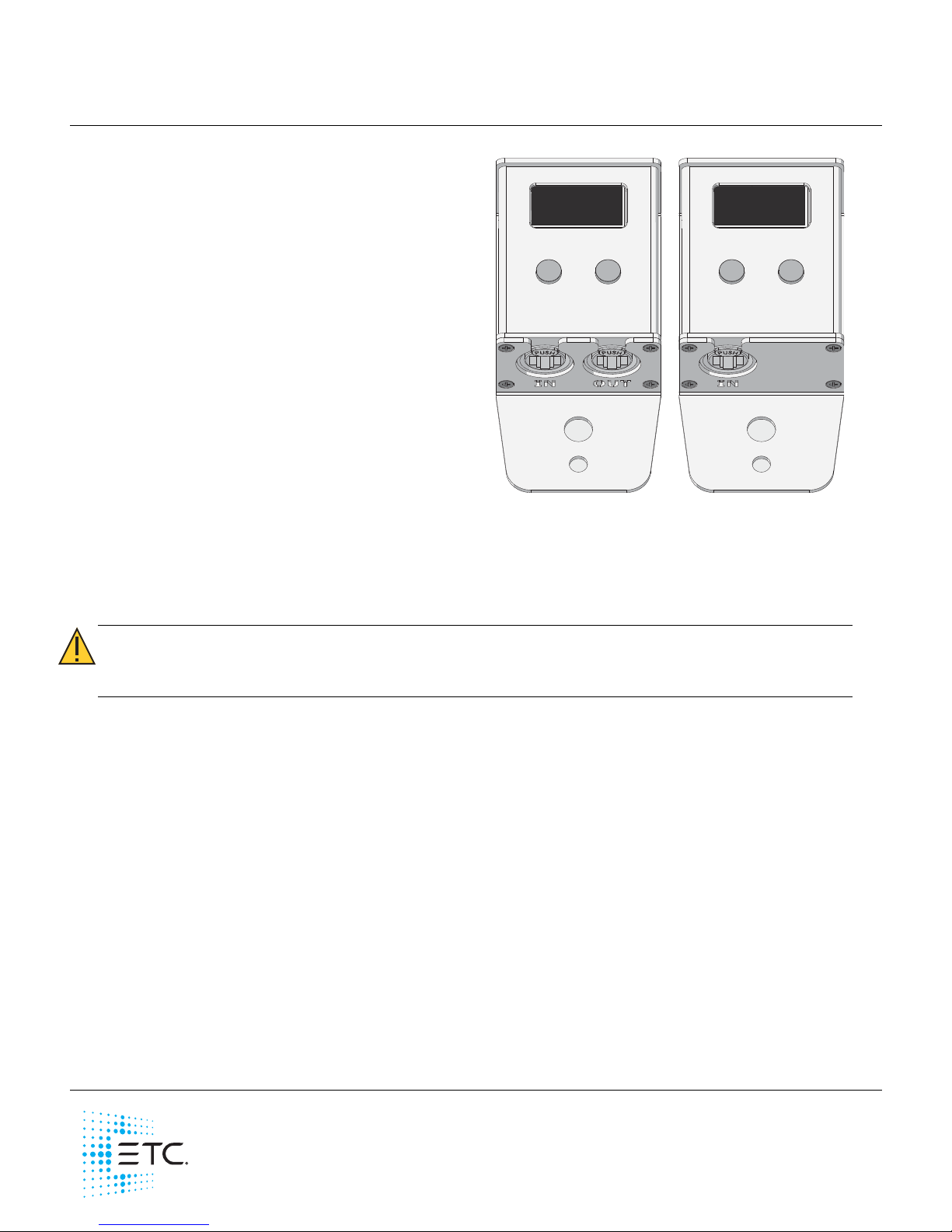
CueSpider includes two RJ45/etherCON®
connectors for connection to the CueSystem network and to link additional CueSpider series outstations.
CueSpider Lite includes one RJ45/etherCON connector for connection to the CueSystem network or to a
CueSpider. CueSpider Lite cannot be connected to another CueSpider Lite.
1: Connect the first station on the communication bus.
• Connect an Ethernet cable (not provided) between the CueSpider or CueSpider Lite “IN” RJ45
connector and the PoE Ethernet network switch.
2: Connect a second CueSpider or connect a CueSpider Lite to a CueSpider.
• Connect an Ethernet cable (not provided) between the CueSpider “OUT” RJ45 connector and
the “IN” on the next CueSpider or the CueSpider Lite.
Reset to Factory Defaults
To return a CueSpider series outstation to factory defaults:
1: Disconnect all Ethernet cables from the CueSpider or CueSpider Lite.
2: Insert a small pin into the hole in the top of the outstation until the internal reset button is depressed,
and then reconnect the Ethernet cable to the “IN” connector.
3: Continue depressing the reset button until the “ETC” screen displays, and then release the reset
button. The CueSpider or CueSpider Lite will return to factory settings and begin to search for an IP
address from the DHCP server.
CAUTION:
Due to the show-critical nature of CueSpider outstations, ETC recommends the
use of NEUTRIK
®
etherCON connectors to minimize the risk of inadvertent device
disconnection.
CueSpider CueSpider Lite
Page 2

ETC Installation Guide
CueSystem CueSpider Series
CueSystem CueSpider Series Page 2 of 2 ETC
Programming and Operation
Please see the
CueSystem User Guide
for programming and operation of CueSystem devices. This
document is available for free download at etcconnect.com/cuesystem.
Help from Technical Services
If you experience difficulty during setup or installation of the CueSystem CueSpider series outstation,
additional information is available from etcconnect.com, or by contacting ETC Technical Services at your
local office listed at the bottom of the first page.
 Loading...