

ETC 7060A3169, 7060A3171 User Manual

Assembly Guide
Production Dates: September 2004 - Present
ATTENTION: The part numbers listed in this guide may differ from the parts
required for your particular Source Four fixture. Part numbers for
fixtures change occasionally as parts are replaced or upgraded.
To ensure that you are ordering the proper part for your specific
fixture, please contact your ETC dealer, or ETC Customer Service
for assistance.
Copyright © Electronic Theatre Controls, Inc.
All Rights reserved.
Product information and specifications subject to change.
Part Number:
7060M2500-05.02
Released: July 2006
Rev B

Table of Contents
Basic Assembly . . . . . . . . . . . . . . . . . . . . . . . . . . . . . . . . . . . . . . . . .1
Lamp Socket Assembly . . . . . . . . . . . . . . . . . . . . . . . . . . . . . . . . . . .2
Assemble lamp socket. . . . . . . . . . . . . . . . . . . . . . . . . . . . . . . . .3
Reflector Housing Assembly . . . . . . . . . . . . . . . . . . . . . . . . . . . . . . .6
Remove reflector . . . . . . . . . . . . . . . . . . . . . . . . . . . . . . . . . . . . .7
Install reflector . . . . . . . . . . . . . . . . . . . . . . . . . . . . . . . . . . . . . . .8
Clean reflector . . . . . . . . . . . . . . . . . . . . . . . . . . . . . . . . . . . . . . .8
Front Barrel Assembly . . . . . . . . . . . . . . . . . . . . . . . . . . . . . . . . . . . .9
Assemble front barrel. . . . . . . . . . . . . . . . . . . . . . . . . . . . . . . . .10
19°, 26°, 36°, and 50° Lens Tubes . . . . . . . . . . . . . . . . . . . . . . . . . .12
Assemble lens tube (19°, 26°, 36°, and 50°) . . . . . . . . . . . . . . .13
Cleaning 19°, 26°, 36°, and 50° glass lenses . . . . . . . . . . . . . .14
10° Lens Tube . . . . . . . . . . . . . . . . . . . . . . . . . . . . . . . . . . . . . . . . .15
5° Lens Tube . . . . . . . . . . . . . . . . . . . . . . . . . . . . . . . . . . . . . . . . . .16
Assemble 5° and 10° lens tubes . . . . . . . . . . . . . . . . . . . . . . . .17
Clean 5° and 10° polymer lenses . . . . . . . . . . . . . . . . . . . . . . .17
ETC®, Emphasis®, Expression®, Insight™, Imagine™, Focus™, Express™, Unison®, Obsession® II, ETCNet2™,
EDMX™, Source Four
of Electronic Theatre Controls, Inc. in the United States and other countries.
All other trademarks, both marked and not marked, are the property of their respective owners.
i Table of Contents
®
, Revolution®, Sensor®, and WYSILink™ are either registered trademarks or trademarks
Basic Assembly
4
5
6
7
8
9
3
1
12
2
2A
10
11
10
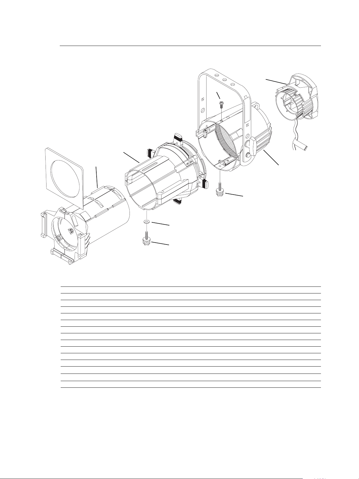
Figure 1
Reference
Number
1 7060A2008 Lamp socket assembly 1
2 7060A2011 Rear housing assembly, single clutch 1
2A 7060A2020 Rear housing assembly, double clutch 1
3 7060A2012 Front barrel assembly 1
4 7060A2000-K 5° lens tube, with knob (See page 16)1
5 7060A2001-K 10° lens tube, with knob (See page 15)1
6 7060A2002-K 19° lens tube (6 x 16), with knob 1
7 7060A2003-K 26° lens tube (6 x 12), with knob 1
8 7060A2004-K 36° lens tube (6 x 9), with knob 1
9 7060A2005-K 50° lens tube (4.5 x 6), with knob 1
10 7060A4008-01 Knob set with male insert 2
11 HW5143 Washer, flat fiber 1
Part
Number
Description Quantity
Required
Optional Equipment
12 HW5197 Screw, 1/4-20 x 5/8, black zinc 1
Basic Assembly 1
Lamp Socket Assembly
11
13
1
20
22
25
17
2
3
6
5
18
14
10
22
21
12
8
19
7
9
16
15
4
24
23
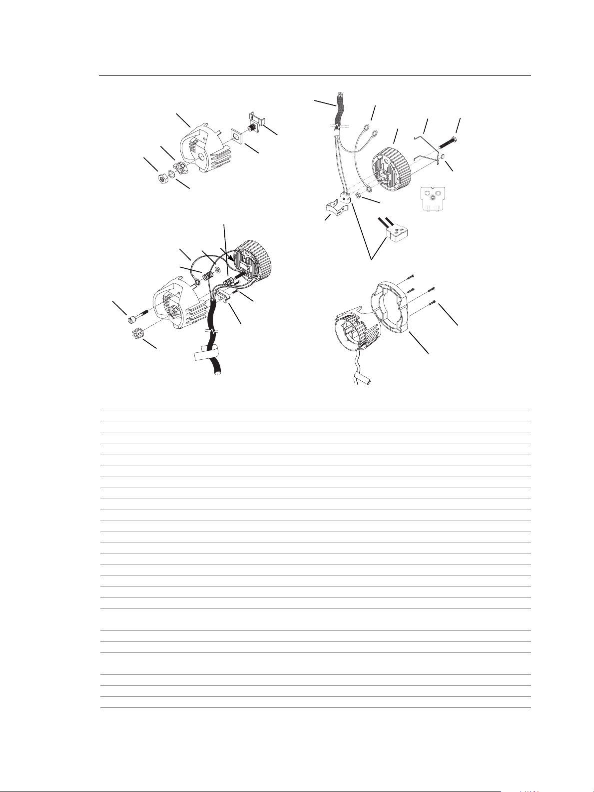
Figure 2
Reference
Number
1 7060A3055 Housing, socket, casting, painted 1
2 7060A3057 Socket, light baffle casting, painted 1
3 7060A4007 Knob, X-Y, lamp set 1
4 7060A4008-02 Knob, Z, lamp set w/female insert 1
5 7060A4011 Bushing, cup 1
6 7060A3011 Hub, index, casting 1
7 7060A3012 Spring, lamp retainer 1
8 HW748 Spring, compression 1
9 7060B7019 Complete UL socket assembly 1
10 HW534 Nut, hex, 1/4-20, black zinc 1
11 7060A3025 Screw, 1/4-20 knurled head 1
12 HW746 Retaining ring, flat, Southco 1
13 HW5123 Nut, hex, 9/16-18, black zinc 1
14 HW747 Washer, wave 1
15 7060A3056 Clamp, strain relief, painted 1
16 HW3103 Screw, 8-32 x 5/8 PhFHMS, black zinc 2
17 HW5122 Bolt, 1/4-20 x 1.75, full thread, black zinc 1
18 HW8209 Clip Tinnerman 1
19 7060B7003
20 W6195 36" sleeve, fiberglass 1
21 HW749 Spring, ground 1
22 7060B7007
23 7060A4037 Handle, insulated rear, black 1
24 HW2181 Screw, 6-32 x 3/4, Taptite 4
25 7060A3085 Source Four Lamp Retainer Wire 1
Part
Number
Description Quantity
48" W420 wire, 16 gauge, 200° C/300V, green UL 1180/CSA AWM
with lug J490T installed
4" W420 wire, 16 gauge, 200° C/300V, green, UL 1180/CSA AWM
with two J490T lugs installed
Required
1
1
2 Source Four Assembly Guide
Assemble lamp socket
Tools Required:
• Open-end adjustable wrench or a 7/16” socket
• Needle-nose pliers
• #2 Phillips screwdriver
18
25
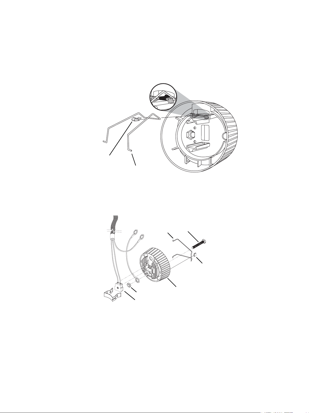
Figure 3
Step 1: Set the crossbar of the retainer clip (25) under the two hooks on the clip bracket
as shown in Figure 3.
Step 2: Place the Tinnerman clip (18) over the retainer clip crossbar between the two
hooks and press it down firmly until it snaps into place.
22
19
10
97
Step 3: Insert the bolt (17) through the light baffle socket casting (2). See Figure 4.
Step 4: Install the green ground wire assemblies (19 and 22) on the bolt (17) with the
prongs on the crimped connectors toward the casting. Run both wires through
the indent in the lip around the bolt hole. Secure with nut (10) and torque to 60
inch pounds.
Step 5: Place the socket assembly (9) into the light baffle socket casting (2). Be sure it is
well seated.
25
17
18
2
Figure 4
Lamp Socket Assembly 3
Step 6: Install the lamp retainer spring (7). The lamp retainer spring secures the socket.
Insert the spring one end at a time, making sure the rectangular slot in each side
of the spring seats on the corresponding tab in the casting.
Note:
Note:
If the spring does not seat correctly, coax it into place with a screwdriver or needlenose pliers.
6
5
13
14
1
3
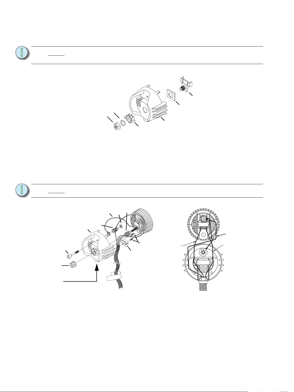
Figure 5
Step 7: Install the bushing cup (5) into the housing socket casting (1) as shown in Figure
5. The cup should slide smoothly up and down, but not side to side.
Step 8: Insert the threaded end of the index hub (6) through the holes in the bushing cup
and the back of the housing socket casting (1).
Step 9: Slide the X-Y knob (3) over the exposed index hub bolt (6), then insert the wave
washer (14) on the bolt and secure with the 9/16 hex nut (13). Hand tighten the
X-Y knob (3).
Install the wave washer with the upward curve toward the hex nut.
4
Cable Clamp in
Housing
222112
8
1
Green
wires
11
16
White
wire
White
wire
15
Figure 6
Figure 7
Step 10: Insert the knurled head screw (11) through the housing socket casting (1) as
shown in Figure 6.
Step 11: Install the shorter green ground wire (22) onto the screw. The prongs on the
crimped connector should be toward the casting.
Step 12: Install the ground spring (21) onto the screw and secure it with the Southco flat
retaining ring (12). Install the Southco ring with its prongs away from the casting.
4 Source Four Assembly Guide
 Loading...