


© ETB Instruments LTD 2007 DigiDash2 Quick Start Guide
D
Version 1.03 - 1 -
DigiDash2 - LITE Display Quick Start Guide
Please read thoroughly before attempting installation of the DigiDash
2
This quick start guide is intended for fast installation and set-up of the DD
2 –
LITE with basic
parameters to get you up and running in a short period. For more detailed instructions on
installation, set-up and operation, please refer to the DD
2
– LITE manual supplied on the
accompanying CD-ROM.
Installation
1. Copy DigiTools (on CD-ROM) to your PC’s Hard Drive
• Insert the DigiTools CD into your CD-ROM Drive.
• Using the mouse, Left double-click on “My Computer” Icon
• Right-Click on CD-ROM Drive Icon and select “Explore”
• Select all files shown on CD-ROM and by Right-Clicking on these files, drag and drop
them into a suitable folder on your Hard Drive.
2. Information Required for Set-up
You will need to obtain some information about your vehicle before starting installation. This is
necessary for the unit to show Speed, RPM and Engaged Gear. These are:-
• Transmission type (e.g. Rear wheel drive with speed sensor mounted on prop-shaft).
• Tyre Size (e.g. 205/50/15”)
• Differential Ratio (e.g. 3.62:1)
• Gear Ratios (e.g. 1
st
Gear – 3.65:1, 2nd Gear 1.97:1….)
• ‘Speedo Cal’ – (Obtained from using DigiDash
2
Tools ‘Calculator’ software on the CD)
• ‘Gear Cal’ – (Obtained from using DigiDash
2
Tools ‘Calculator’ software on the CD)
Please refer to the Sheet entitled ‘DigiDash2 – LITE Wiring Schematic’
1. Connect DigiDash2 to 12 volt supply
The cable supplied with a RED 9-pin connector should be connected to the Display module.
Connectors are gender specific to prevent incorrect connection.
Of the wires coming out of this green connector, you will find a RED wire with black fuse
holder, and a single BLACK wire. Connect the RED wire to a switched +12v (positive) supply
(usually this is a 12 volt feed from your ignition switch), and connect the black wire to the
vehicle Ground (negative (-ve)). It is more preferable to connect the RED wire to a position on
the Ignition switch that does not require the engine to be running.
2. Install Sensors supplied and connect according to Wiring Schematic
After installing the sensors supplied with the unit, connect wires as shown on the wiring
schematic, either directly using the cable supplied or to an existing wiring harness.
3. Turn on your Vehicle Ignition Switch
Switch on Ignition in order to supply 12 volts to the DigiDash2 and the Display will power up
and go through its initial start-up sequence.
© ETB Instruments LTD 2007 DigiDash2 Quick Start Guide
D
Version 1.03 - 2 -
Initial Set-up Using DigiDash2 – LITE Display
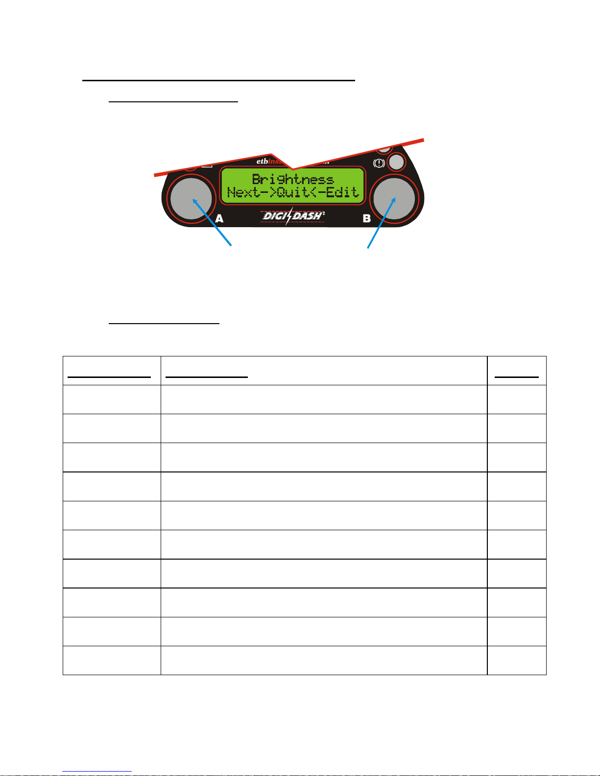
1. Enter Configuration Menu
In order to begin basic configuration of the DigiDash
2 –
LITE, you will need to select the set-up
menu.
To enter the set-up Menu, Hold Down Buttons A & B Together
To move to the next Menu screen, press Button ‘A’. To Edit the Menu displayed, press Button
‘B’. Once you have finished editing a particular Menu screen, press Button ‘A’ (shown on LCD
as ‘OK’) to return the Main editing menu.
2. Editing Configuration
There are 30 menu displays for editing the set-up of the DigiDash2. The majority of the Menu
editing functions are self-explanatory. The key parameters that require initial editing are:-
Menu Display Edit Function Default
MPH or KMH
Select units of Speed and Odometer (Miles or Kilometres) MPH
Shift RPM
Sets the maximum RPM limit (Point at which main RED shift LED is lit.) 6000rpm
Shift Delta
Sets the RPM increments of each shift LED (e.g. 200rpm) 200rpm
Pulses/Cycle
Sets the numbers of engine cylinders. Note that on certain types of ignition systems the output
pulses of the system may not match the number of engine cylinders. This number can be
changed from 1 to 8 to accommodate this.
2
Speedo Cal
Numeric factor dependent on speed sensor location, tyre size and differential ratio. Obtained
from DigiTools Calculator software.
Gear Cal
Numeric factor dependent on Gear and Speed ratios. Obtained from DigiTools Calculator
software.
Primary Ratio
On a vehicle using a car engine and gearbox, this ratio is usually 1:1. On vehicles using
motorcycle engines and gearboxes, this ratio can be set using this menu function.
1:1
Num Gears
Sets the number of forward gears in the gearbox 6
Gear 1
Allows the user to enter the ratio of 1st gear. Please note that when entering Gear ratios, the ratio
displayed is in abbreviated format. (e.g. the ratio of 2.657:1 is shown as 2657)
Gear 2-6
Allows the user to enter the gearbox ratio of 2nd Gear. The next 4 menu screens are for entering
the gearbox ratios for gears 3 to 6.
Once editing is complete, press and hold Buttons A & B together and you will be asked
whether you wish to exit set-up. Press Button A to select ‘YES’ and exit.
© ETB Instruments LTD 2007 DigiDash2 Quick Start Guide
D
Version 1.03 - 3 -
3. Speed Sensor Installation
There are 2 small, powerful magnets supplied with kit. You must use both magnets for the
DD2 to read correctly. These magnets are mounted on a surface that rotates in relation to
vehicle speed and supply electrical pulses as they pass in front of the speed sensor to the
DigiDash
2
.
The harness with the RED 9-pin connector incorporates the speed sensor. The sensor can be
disconnected from this harness to aid ease of installation.
You must first locate a suitable position for mounting the speed sensor and magnets on your
vehicle. The speed sensor and magnets are commonly mounted in one of three locations: -
• Prop-shaft (either at the differential end or gearbox end)
• Drive-shaft Coupling ( with Sensor mounted on Gearbox)
• Front Hub (with sensor mounted on steering arm)
The recommended gap between the sensor and top surface of the magnets is 1mm and
therefore you must ensure that whatever location is used, any movement in the position of the
magnets is replicated in the movement of the sensor to maintain a constant gap.
You will need to fabricate a strong bracket to hold the sensor in place, and bolt this bracket to
a suitable mounting point.
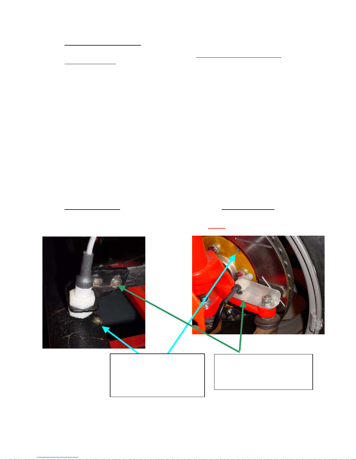
Here are 2 examples:-
Prop-Shaft Mounting Front-Hub Mounting
Important! – The speed sensor is polarity dependent. This means that the magnets
must be mounted dimple-side DOWN.
Important! - The recommended gap between the speed sensor head and top surface of
the magnets is 1mm.
Magnets glued in position.
Liberal application of a strong
adhesive such as ‘Chemical
Metal’ or ‘Araldite’ will ensure
that the magnets do not become
dislodged during use.
Strong mounting brackets that
hold the speed sensors in
position. The brackets have been
mounted in positions that move in
unison with the ma
g
nets.

© ETB Instruments LTD 2007 DigiDash2 Quick Start Guide
D
Version 1.03 - 4 -
4. Connecting the Tachometer (RPM)
As well as the speed sensor cable, the RED 9-pin connector incorporates the yellow
tachometer-input wire.
If the vehicle’s ignition system uses an ignition coil, the yellow tachometer wire should be
connected to the Negative (-ve) side of the ignition coil.
If the engine has an engine management system (or ECU), with a dedicated Tachometer
output, the yellow tachometer input should be connected to this output from the ECU.
5. Test Mode
The Configuration menu (See above) accessed by holding down buttons A&B together has a
TEST MODE for verifying the presence of a signal input for Speed, RPM and Lap timer
receiver. To test the speed sensor is reading the magnets, enter Test Mode and rotate the
part on which the magnets are mounted. A ‘++’ sign should appear under the heading ‘SP’
each time a magnet passes in front of the sensor head. To test the lap trigger receiver, any
infra-red TV remote Control can be used – by pressing a button on the handset, a ‘++’ sign
should appear under the ‘LT’ (and ‘SW’) heading.
General Safety Instructions
• When connecting wires to your vehicle’s wiring loom, always ensure the negative pole of
the battery is disconnected prior to starting work to prevent short circuits.
• Connect cables in accordance with the electrical wiring schematic.
• When routing cables, use existing cable ducts or conduits where possible and fix in place
using suitable cable tape.
• Avoid routing wires near existing cables that carry high current, in particular the ignition
cables, fuel pump wires or heater fan cables.
• Do not route cables over mobile components.
• If wires are routed through drilled holes, protect them with rubber sleeves or similar.
• Insulate any exposed strands of cable so that no short-circuiting can occur.
• Always ensure that the vehicle cannot be accidentally started whilst working on the
vehicle.
• Double-check all connections before re-connecting the battery.
Help & Advice
Should you require help and advice when installing and configuring the DigiDash2 please
contact ETB and we will do our best to help.
ETB Instruments Limited
Unit 15 Brookside, Sumpters Way
Temple Farm Industrial Estate
Southend-on-Sea
Essex
SS2 5RR
United Kingdom
Tel: + 44 (0) 1702 601055
Fax: + 44 (0) 1702 601056
Email: info@etbinstruments.com
 Loading...