

Page 1
EN
OPERATING INSTRUCTIONS AND MAINTENANCE
FR
UNI EN ISO 9001:2008
www.etatronds.com
eSelect-CD1
Page 2

Page 3

Page 4

(IT) DIRETTIVA "RAEE" 2002/96/CE E SUCCESSIVA MODIFICA 2003/108/CE SUI RIFIUTI DI APPARECCHIATURE ELETTRICHE
ED ELETTRONICHE
Il simbolo sotto riportato indica che il prodotto non può essere smaltito come normale rifiuto urbano. Le Apparecchiature Elettriche ed
Elettroniche (AEE) possono contenere materiali nocivi per l'ambiente e la salute e pertanto devono essere oggetto di raccolta
differenziata: smaltite quindi presso apposite discariche o riconsegnate al distributore a fronte dell'acquisto di una nuova, di tipo
equivalente o facente le stesse funzioni. La normativa sopracitata, alla quale rimandiamo per ulteriori particolari e approfondimenti,
prevede sanzioni per lo smaltimento abusivo di detti rifiuti.
(UK) WASTE OF ELECTRICAL AND ELECTRONIC EQUIPMENT DIRECTIVE (WEEE, RAEE in Italy) 2002/96/EC AND
SUBSEQUENT AMENDMENT 2003/108/EC
The marking shown below indicates that the product cannot be disposed of as part of normal household waste. Electrical and
Electronic Equipment (EEE) can contain materials harmful to health and the environment, and therefore is subject to separate waste
collection: it must be disposed of at appropriate waste collection points or returned to the distributor against purchase of new equipment
of similar type or having the same functions. The directive mentioned above, to which make reference for further details, provides for
punitive actions in case of illegal disposal of such waste.
(FR) DIRECTIVE "RAEE" 2002/96/CE ET MODIFICATION SUCCESSIVE 2003/108/CE CONCERNANT LES REBUTS
D'APPAREILLAGES ÉLECTRIQUES ET ÉLECTRONIQUES
Le symbole ci-dessous indique que le produit ne pas être éliminé comme un normal déchet urbain. Les Appareillages Électriques et
Électroniques (AEE) peuvent contenir des matériaux nocifs pour l'environnement et la santé et doivent donc faire l'objet de collecte
différenciée: éliminés donc auprès de décharges prévues à cet effet ou rendus au distributeur pour l'achat d'un nouveau, de type
équivalent ou ayant les mêmes fonctions. La réglementation susmentionnée, à laquelle nous vous renvoyons pour les détails et les
approfondissements ultérieurs, prévoit des sanctions pour la mise en décharge abusive desdits rebus.
(ES) DIRECTIVA "RAEE" 2002/96/CE Y MODIFICACIÓ N SUCESIVA 2003/108/CE SOBRE RESIDUOS DE APARATOS ELÉ
CTRICOS Y ELECTRÓ NICOS
El símbolo que se muestra abajo indica que el producto no puede eliminarse como un residuo urbano normal. Los Aparatos Eléctricos y
Electrónicos (AEE) pueden contener materiales nocivos para el medio ambiente y la salud y por tanto tienen que ser objeto de
recogida selectiva: por consiguiente tienen que eliminarse en vertederos apropiados o entregarse al distribuidor cuando se adquiera
uno nuevo, del mismo tipo o con las mismas funciones. La normativa mencionada arriba, a la que remitimos para más detalles y
profundizaciones, prevé sanciones por la eliminación clandestina de dichos residuos.
(PR) DIRETRIZ "RAEE" 2002/96/CE E MODIFICAÇÃO POSTERIOR 2003/108/CE SOBRE RESÍDUOS DE
EQUIPAMENTOS ELÉTRICOS E
ELETRÔNICOS
O símbolo referido abaixo indica que o produto não pode ser eliminado como resíduo urbano normal.
Os Aparelhos Elétricos e
Eletrônicos (AEE) podem conter materiais nocivos ao ambiente e à saúde e, portanto, devem
ser objeto de coleta seletiva: eliminados, portanto,
através de depósitos apropriados ou pelo reenvio ao distribuidor
para a aquisição de um novo, de tipo equivalente ou que
realize as mesmas funções.
Anormativa referida acima, à qual nos referimos para detalhes complementares e
esclarecimentos, prevê
sanções no caso de eliminação inadequada de tais resíduos.
Page 5

ENGLISH
5
TABLE OF CONTENTS
SAFETY STANDARDS ................................................................................................................................................. 7
User information signs .................................................................................................................... 7
CONTROLLER DESCRIPTION .................................................................................................................................... 8
TECHNICAL CHARACTERISTICS .............................................................................................................................. 8
HINTS AND WARNINGS .............................................................................................................................................. 9
Warning .......................................................................................................................................... 9
Shipping and Transporting ............................................................................................................... 9
Proper use of the controller ............................................................................................................. 9
Risks .............................................................................................................................................. 9
Assembling and dismantling the equipment ..................................................................................... 10
ESELECT-CD1 SERIES ENCLOSURES, MOUNTING, COMMISSIONING AND OVERALL DIMENSIONS ............ 10
Wall mounting enclosure eSelect-CD1 ............................................................................................. 10
Overall dimensions ......................................................................................................................... 11
Electrical wiring co nnectors ........................................................................................................... 11
Connecting conductivity sensor ...................................................................................................... 11
Connecting to main power supply / PARALLEL CO NNECTIONS ........................................................ 12
Example connection controller-motor dosing pum p relays OUT 1-2................................................... 12
DISPLAY DESCRIPTION ........................................................................................................................................... 13
TERMINAL BOARD ELECTRICAL WIRING .............................................................................................................. 14
OPERATING MODES GLOSSARY ............................................................................................................................ 15
PROGRAMMING FUNCTIONS .................................................................................................................................. 17
INPUTS / OUTPUTS DIAGRAM FUNCTIONS ........................................................................................................... 17
INITIAL DISPLAY ....................................................................................................................................................... 18
Selecting Language ........................................................................................................................ 18
Selecting Conductivity (EC) “K” factor ............................................................................................ 18
TEMPERATURE settings .................................................................................................................. 19
Programming MENU ........................................................................................................................ 19
MAIN MENU > BASIC PROGRAMMING MENU ................................................................................................... 20
SETPOINT 1 EC CONDUCTIVITY > BASIC MENU ............................................................................................. 20
SETPOINT 2 EC CONDUCTIVITY > BASIC MENU .............................................................................................. 21
SENSOR CALIBRATION > BASIC MENU ............................................................................................................... 22
SETTINGS > BASIC MENU ...................................................................................................................................... 22
MAIN MENU > EXPERT PROGRAMMING MENU ................................................................................................ 23
SETPOINT 1 EC CONDUCTIVITY > EXPERT MENU ........................................................................................... 23
SETPOINT 2 EC CONDUCTIVITY > EXPERT MENU ........................................................................................... 25
4-20MA ANALOG CURRENT OUTPUT FUNCTION SELECTION > EXPERT MENU ............................................ 27
4-20mA EC CO NDUCTIVITY > AUX FUNCTIO N .............................................................................. 27
4-20mA EC Conductivity > DOSING SETPOINT ................................................................................. 27
SENSOR CALIBRATION > EXPERT MENU ............................................................................................................ 28
Page 6

6
ENGLISH
SETTINGS > EXPERT MENU ................................................................................................................................ 29
CONDUCTIVITY SENSORS AND MAINTENANCE ................................................................................................... 30
CONDUCTIVIT Y sensors NOT ES ....................................................................................................... 30
CONDUCTIVITY sensors maintenance .............................................................................................. 30
CONDUCTIVITY sensors range ......................................................................................................... 31
TROUBLESHOOTING ................................................................................................................................................ 31
Page 7

ENGLISH
7
eSelect-CD1 CONTROLLER SERIES INCLUDES SCREWS FOR WALL MOUNTING
eSelect-CD1 series is NOT provided with sensors, which are available upon request.
ETATRON D.S. declines any responsibility in case the controller is used with other brand probes and sensors
SAFETY STANDARDS
User information signs
WARNING: ignoring safety information can endanger life or result in serious injury!
CAUTION: ignoring safety information can result in injuries to persons or damage systems or materials!
HIGH VOLTAGE: ignoring this sign can result in death or serious injuries to persons!
NOTE or INFORMATION SOURCE
- this symbol “pointing finger” indicates programming steps.
- if no keys are pressed within 60 seconds, controller will display current measurements
Qualified and authorized personnel must carry out any work or repair on the unit: manufacturer declines any responsibility for
consequences in case this rule is not complied.
Unqualified personnel should keep away from the plant and/or hazard areas.
The official operator of the system or the plant, when installing the unit, is responsible to fulfil the above rules.
Page 8

8
ENGLISH
CONTROLLER DESCRIPTION
The eSelect-CD1 is a compact system with ELECTRICAL CONDUCTIVITY (EC) controller. In many cases, conductivity is linked directly
to the total dissolved solids (T.D.S.): conductivity provides an approximate value for the TDS concentration, usually to within ten-percent
accuracy. eSelect-CD1, along with the high quality performance in terms of measurements and functions thus satisfying most of the
requirements for an instrument, it offers many features thus making it extremely versatile and easy to operate. Conductivity measurement are
in micro Siemens features 4 K factor ranges (Cell Constant) suitable for following K:
Controller covers ranges from costant K 1 up to 20.00 mS and even 100.00 mS (latter with graphite sensor electrodes) and costant K 5
ranges 2.000 μS;
BENEFIT: The above feature allow dealers to stock one type for all controller thus reducing stock value or saving problems when
issuing orders to manufacturer.
Two types of programming menu:
• Basic making life easier for those home applications such small swimming pool or water treatment systems;
• Expert for professionals giving the opportunity to refine measurements and safety functions.
A friendly user menu programming it is almost self-explanatory and the elegant wide display allows easy vision.
TECHNICAL CHARACTERISTICS
Conductivity EC Measuring range and
K factor (cel
constant):
▪ K 1 ranges up to 20.00 mS and even 100.00 mS (latter with graphite sensor
electrodes) / Hysteresis / PWM point = 500 μS
Resolution 10 μS
▪ K 5 ranges up to 2.000 μS / Hysteresis / PWM point = 50 μS
Resolution 1 μS
▪ K10 ranges up to 200 μS / Hysteresis / PWM point = 0,50 μS
Resolution 0,1 μS
▪ K 0.1 ranges up to 100.00 mS / Hysteresis / PWM point = 5000 μS
Resolution 100 μS (only with graphite sensor electrodes)
Temperature setting:
automatic with combined conductivity + PT100 or NTC system
Temperature probe range:
– 20 ....100°C
▪ Resolution 0.1% °C ▪ Accuracy: ± 0.5% °C
Power supply / Power consumption:
Universal power supply 100÷250 Vac / 5W at 240 V AC
Microprocessor technology: SMD components mounting, digital controls keypad 6 key
Linearity, Stability Reproducibility:
± 0.5 % under standard conditions
Display: back-lit custom display (126x64); Display visible area 70x37 mm
Delay: Delay time relay activation, programmable for each set-point (999 sec.)
Start-up Delay: Delay time relay when switching ON, programmable on each set-point
PARAMETER
VALUE
Measure
Conductivity up tol 20mS
Type of probe
PTFE with graphite electrodes, k=1
Power supply
100÷240 Vac – 50/60 Hz – 6W
Display
Graphic 128x64 (visible area 70x37 mm)
Power supply protection
The whole power pack (there is no fuse)
Temperature probe
PT100, 0,1°C resolution
External casing
ABS, IP65
Inputs
Level, Proximity
Relay outputs
2 relay outputs (set-point 1 and set-point 2) ON-OFF or PWM type
Relay outputs features
maximum 5A on resistive load, maximum 1A on inductive load, 230Vac
mA outputs
1 mA galvanically separated output
mA outputs features
500 ohm maximum load impedence
Alarm
Overdosing alarm
Accessories
Wall mounting kit
Measures
120 x 200 x 90,5
Weight
Net weight: 1230 gr - Gross weight: 1255 gr
Front controls
Polycarbonate adhesive
Working temperature
0÷50 °C
Page 9
ENGLISH
9
Power consumption / Nominal current: 230V=6W, 100mA / 24Vac-dc=7W, 300mA / 12Vdc=7W, 600mA
Internal electrical protection: power supplier guarantees electrical protection (instead of fuse)
Level / Remote relay control Chemical additive level (level switch not included)
Outputs:
Output RELAY 1 (set-point 1) ON-OFF or PWM mode voltage free contact 5Amax 230Vac
Output RELAY 2 (set-point 2) ON-OFF or PWM mode voltage free contact 5Amax 230Vac
FLUX sensor (proximity switch) It blocks output operations in case of no flow into the sensor cell
Unit load
Resistive load 5A max 230 V AC / Inductive load 1A 230 V AC
Insulation voltage relay output: > 3000 Vac
Relay contact lifespan > 105 switching operations (at 3 A /230Vac)
0/4...20 mA output EC
Adjustable (500 Ω max input impedance), galvanic separation
Noise Level: Irrelevant
Working temperature: Ideal working temperature 5°C÷40°C, withstand 0°C÷45°C.
Environmental Conditions: Possibly dry environment, altitude up to 2000m, Relative humidity 80% for
temperatures up to 31°C decreasing linearly to 50% relative humidity at 40°C.
Pollution degree 2.
Transport and storage conditions:
– 5÷60°C possibly dry environment
HINTS AND WARNINGS
Please read the warning notices given in this section very carefully, because they provide important information regarding safety in
installation, use and maintenance of the unit.
• Keep this manual in a safe place, so that it will always be available for further consultation.
• The company manufactured the unit in accordance with best practice. Both its lifetime and electrical and mechanical reliability will
be enhanced if it is correctly used and subjected to regular maintenance.
Warning
Qualified and authorized personnel must carry out any intervention or repair for the unit; manufacturer declines any responsibility
for consequences in case this rule is not complied.
Shipping and Transporting
Shipment is always at the purchaser's risk. Claims for any missing materials must be made within 15 (fifteen) days of goods arrival,
while claims for defective materials will be considered within 30 (thirty) days from the same date. ETATRON D.S. authorized personnel must
previously agree the return of the equipment or other materials.
Proper use of the controller
• Controller must be used only for the purpose for which it has been expressly designed, namely the controlling and measuring
physical-chemical values.
• Any different use of it must be considered improper therefore dangerous.
• All other applications or modifications are prohibited.
• The equipment is NOT designed for use in explosion-hazardous locations.
• The unit can only be used for applications where technical requirements meet the ones of ETA TRON D.S. characteristics and
specification data shown in the present operating booklet.
• The vendor is not liable for damage deriving from improper and/or unreasonable use of the unit.
Risks
• After unpacking the equipment, ensure it is in good shape and form. In case of doubt, do not use it and contact qualified personnel. Keep
out of reach of children packing materials (plastics bags, polystyrene, etc.) being potential sources of danger. However, save packaging: it
can be useful for future shipments.
• Before connecting the equipment ensure voltage ratings corresponds to local power supply. You will find these characteristics in the product
label placed on the equipment and packing.
Page 10

10
ENGLISH
Caps (A) x 4
• The electrical installation must comply with the standards and rules in force in the country where it is utilised.
• Use of electrical equipment always implies observance of some basic rules:
1 - Do not touch the equipment with wet or damp hands or feet;
2 - Do not operate the equipment with bare feet (example: swimming pool equipment);
3 - Do not leave the equipment exposed to the action of the atmospheric agents;
4 - Do not allow the equipment to be touched by children or used by unskilled individuals without supervision;
• When commissioning the unit or in case of emergencies or improper functioning, the controller should be switched off
immediately. Disconnect the power cable from the main power supply! Contact our technical assistance for any necessary repairs,
use only original spares! Failure to respect this condition could render the equipment unsafe to use.
• When carrying out any repairs or opening the unit, ensure to disconnect it from power supply.
• When there is no longer use requirement of installed equipment, ensure to disconnect it from power supply.
1. Disconnect power from mains or from the single-pole switch-contact.
2. Take all due safety precautions during unit service (gloves, goggles, overalls, etc.).
Assembling and dismantling the equipment
ASSEMBLY: all ET ATRON D.S. controllers are fully assembled. For the wall mounting, please proceed as follows.
DISMANTLEMENT: before dismantling the unit or carrying any operation, disconnect power.
ESELECT-CD1 SERIES ENCLOSURES, MOUNTING, COMMISSIONING AND OVERALL DIMENSIONS
Wall mounting enclosure eSelect- CD1
eSelect-CD1 enclosure ABS plastic 200w x 106h x 90,5d
To access the 4 wall mounting points remove the 4 mounting point closures (A) located in each corner of the controller.
The enclosure features 4 captive screws for a quick opening/closing of the lid thus allowing easy access for commissioning and
service and also guarantees a perfect seal for long time operation
a. - Install the unit in a dry place and well away from heat sources; max environmental temperatures 40°C.
b. - Carefully observe regulations in force in the various countries as in regards electrical installations.
c. - Mount the controller on the wall using the screws and dibbles provided with the unit
VERY IMPORTANT NOTE FOR ENCLOSURE: when handling the unit bear in mind not to pull, drag, or mistreat the flat cable
connecting the pcb display placed on the lid with main pcb.
Page 11

ENGLISH
11
Overall dimensions
Electrical wiring connectors
eSelect-CD1 is provided with 2 multiple cable glands for various input and output cable wirings. Complying with International
electrical wiring rules., we advice not to connect more then one equipment on each pin.
CONNECTORS GLANDS USE:
Cable gland 1: Power cable
Cable gland 2 and 3: Recommended use for:
• Set-points relay outputs
• mA output
• Level probes for chemical tanks
• 12Vdc input
• Flow sensor
• AUX output
• Conductivity sensor
• Temperature Sensor
Connecting conductivity sensor
eSelect-CD1 works with simple conductivity 2-electrode open sensors, with AISI 316 and Graphite electrodes.
NOTE FOR CONDUCTIVITY SENSORS
eSelect-CD1 works with simple conductivity 2-electrode open sensors, AISI 316 OR Graphite electrode.
FOR CONDUCTIVITY SENSORS with internal temperature sensor: due to the various types on the m arket, in case operator w ished
to use such sensor, use PT100 temperature sensors, please contact ETATRON D.S. service or Local Dealer to get the right
configuration. eSelect-CD1 is NOT suitable for inductive EC sensors!
Install conductivity sensor into the system or an off-line holder and connect to Terminal board (see page 13) before connecting to
mains. We recommend using a new electrode or at least in good conditions (not old).
Connect Conductivity sensor to internal terminal board.
PLEASE NOTE:
eSelect-CD1 automatically adjust itself for various conductivity ranges by adapting the controller to the different probes cell constant
“K” characteristic. However, at the beginning of programming and in “Expert Menu Set-point1” user can adjust the required K factor.
It is always RECCOMENDED and mandatory to use the correct K probe according to the range in which the controller is working.
1 3 2
Page 12

12
ENGLISH
- Controller covers ranges from costant K 1 up to 20.00 mS and even 100.00 mS (latter with graphite sensor electrodes) and costant
K5 ranges 2.000 μS;
The controller will adapt also the Measurement and Display resolution according to the type of probe used;
CONTROLLER SENSOR “SENSOR CALIBRATI O N”, check pages 22 and 26
“SENSOR CONFIGURATION AND RANGE” check page 8
Connecting to main power supply / PARALLEL CONNECTIONS
PARALLEL CONNECTIONS: when connecting the unit to main power supply in parallel with other inductive equipment (motors,
pumps, blowers, solenoid and motorized valves), these gears must be electrically isolated and with a proper Ground system, to prevent
damages from inductive voltages when switching ON-OFF.
• try to use a power switch in order to have separate connections via contact relay or relay.
• when this is not possible, contact ETATRON technical service.
EXAMPLE CONNECTION CONTROLLER-DOSING PUMP RELAY OUTPUTS 1-2-3-4
ETATRON controllers are equipped only with clean contact relays to drive actuators (e.g.pumps) as shown in the above diagram. In
case installator
wishes to drive actuators directly from mains, wiring must respond according to local electrical rules and ensuring the
following requirements: Max 3A, Max voltage 250Vac or 30Vdc.
Example connection controller-motor dosing pump relays OUT 1-2
1
CONTROLLER
3
SINGLE PHASE MOTOR METERI NG PUMP
2
POWER RELAY SW ITCH 230V MAX 10A
4
TRI-PHASE MOTOR METERING PUMP
L = one phase of mains network N = neutral r - s - t = represent each phase of tri-phase mains system
SINGLE-PHASE CONNECTIONS DIAGRAM THROUGH POWER RELAY SWITCH
THREE-
Page 13

ENGLISH
13
PHASE CONNECTIONS DIAGRAM T HROUGH POWER RELAY SWITCH
DISPLAY DESCRIPTION
* Info showing as follows:
ALARM MAX - SETPOINT 1
OVERDOSING - SETPOINT 1
ALARM MIN - SETPOINT 1
OVERDOSING - SETPOINT 2
NO LINK
OVERDOSING - 4-20mA
If there are more than one function active, messages appear in a continuous cycle lasting 3 sec. for each item. ALARM or
OVERDOSING messages will disappear once measurements are restored according to programmed settings whilst Overdosing icon will
remain; to delete activated icons from the display, keep pressing on ESC.
When messages appear, temperature status will NOT be shown.
Temperature value**: in case the temperature has been set with Manual mode, the temperature value will correspond to the one
selected. In case has been selected the PT100 mode and such temperature sensor has been connected, the temperature value shown will
correspond to the actual value in the system.
NO LINK: communication break down between controller and display
WHEN OPENING THE LID FOR SERVICING THE UNIT, ALWAYS DISCONNECT POWER SUPPLY!!!
KEEP IN MIND: unit with universal voltage 100÷250Vac (±10%) or 9÷24Vdc. If the actual voltage is constantly at the limit
(lower or higher), or when spikes are much higher than mentioned range, the unit input is electronically protected against
Voltage fluctuations; outside the above mentioned ranges, controller will not function
and circuit boards must be replaced.
We RECOMMEND using voltage protections, checking system ground and, when connecting in parallel other equipment,
using “power switch”. A plant not built according to correct electrical rules, without a ground system, with frequent ON/OFF
operations, could affect directly the circuit boards.
eSelect-CD1 series power and control boards software are linked together via 485 protocol: when in place of the temperature
display is shown “NO LINK” it means there is a problem between the two boards in that case check the electrical flat cable and
wiring connection between the them and contact immediately ETATRON service.
RX measurement
Other unit status here***
Temperature value**
Conductivity measurement
mS / range 20 mS
Messages showing here*
Controller status
Conductivity measurement
µS / range 2000 µS
Back-lit custom display (126x64)
Display visible area 70x37 mm
Page 14
14
ENGLISH
Other status icons shown at bottom line***
Here are displayed some other messages status such as:
S1 S2 L1 ALARM OVERDOSING FLOW “BASIC MENU” “EXPERT MENU”
“BASIC MENU” “EXPERT MENU” these messages appear during programming steps as reminders.
Controller is set as default with * BASIC MENU * which is a simple programming for not professional user keeping all the functions
to a very basic simple menu.
* EXPERT MENU * features other parameters to select thus refining the unit operation and safety functions although programming
is still user friendly.
S1 S2 indicating the correspondent active Set point. When selecting “Mode Timed Pulses” (Pulse With Modulation) during set
point step, the message S1… S2 will flash during PWM operations but when the set point is NOT active there will not be any message.
** FLOW ** shows the absence of water flow into the sensor holder: this is valid only when using a Proximity switch and the “Flow
sensor” is enable which is possible only when using “Menu Expert”.
L1 L2 indicate the “Level” control of external chemical tanks and are only shown once the floating level probe/s are connected to
the terminal block pins IN1 and IN2: when the level into the tank is lower than the level probe floater, this will enable the Status message.
When switching ON the controller for the first time, it will appear a list of all the programming keys function.
Controller covers ranges from costant K 1 up to 20.00 mS and even 100.00 mS (latter with graphite sensor electrodes) and costant
K 5 ranges 2.000 μS. Display will show µS values but in case setpoint value exceed 1999 µS, it will show 2.00 mS (decreasing the value will
return to µS reading). Selecting K5 (5.000) range setpoint value 100 µS.
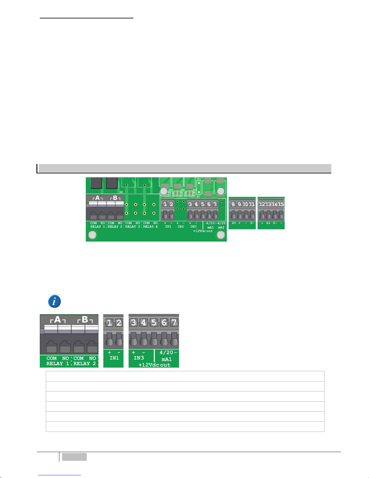
TERMINAL BOARD ELECTRICAL WIRING
WHEN OPENING THE LID FOR SERVICING THE UNIT, ALWAYS DISCONNECT POWER SUPPLY!!!
- Unscrew the front panel and carefully open the lid
- eSelect-CD1 series is provided with 2 m cable already wired; in case user wishes to replace the cable with a longer one, connect
the mains to neutral, phase, unit switches ON, initially display quickly shows the instrument latest software review.
The terminal board is built with special pin for top safety: ensure to twist well the wire ends, use a small screwdriver to
press the safe
ty on top of the slot where insert the wire ends and, according International electrical rules, we do not
recommend to connect more then one equipment on each pin.
Out A Pin COM / N.O.RELAY1 Set-point 1 ON-OFF / output relay PWM timed pulses
Out B Pin COM / N.O.RELAY2 Set-point 2 ON-OFF / output relay PWM timed pulses
Pin 1 + / Pin 2 - IN 1 Digital Input Level switch for chemical tank
Pin 3 + / Pin 4 - IN 3 Proximity Switch input BL ACK + / BLUE – wires
Pin 5 + +12Vdc out Proximity Switch input 12Vdc BROWN wire
Pin 6 / Pin 7 4/20mA 4-20mA proportional output for mA dosing pump or data device
Page 15

ENGLISH
15
Conductivity sensor 2 wires
DO NOT CONNECT BRAIDED WIRE
Pin 8 = S+ RED or WHITE
Pin 9 = +
Pin 10 = –
Pin 11 = S– WHITE or RED
eSelect-CD1 works with simple conductivity 2-electrode open sensors, AISI 316 OR Graphite electrode. F OR CONDUCTIVITY
SENSORS with internal temperature sensor: due to the various types on the market, in case operator wished to use such sensor,
please contact ETATRON service or Local Dealer to get the right configuration for connecting to terminal board. eSelect-CD1 is
NOT suitable for inductive EC sensors!
Temperature probe PT100
DO NOT CONNECT BRAIDED WIRE
Pin 12 = + RED
Pin 13 = S+ BLUE
Pin 14 = S– GREEN
Pin 15 = – YELLOW
KEEP IN MIND: unit with universal voltage 100÷250Vac (±10%) or 9÷24Vdc. If the actual voltage is constantly at the limit (lower
or higher), or
when spikes are much higher than mentioned range, the unit input is electronically protected against Voltage
fluctuations; outside the above mentioned ranges, controller
will not function and circuit boards must be replaced. We
RECOMMEND using voltage protections, checking system ground and, when connecting in parallel other equipment, using “power
switch”. A plant not built according to correct electrical rules, without a ground system, with frequent ON/OFF operations, could
affect directly the circuit boards.
OPERATING MODES GLOSSARY
ON-OFF mode
• Unit is provided with ON-OFF mode which will activate (or deactivate in case of reverse mode ON) output relays Constant / ON-OFF
dosing pumps mode or other ON-OFF equipment.
BENEFITS: it will work with most of ON-OFF equipment, which are also cost effective.
DISAVANTAGES: due to dosing equipment high output performance rate (frequency for dosing pump and peristaltic dispensers with motor
rpm), this will result to a slight different values between actual measurement in the system and what controller shows.
USING EXTRA ON-OFF RELAY OUTPUT
• ON-OFF Relay probably will connect a dosing pump; the free available relays can connect an alarm device (buzzer and light),
programming different values then the ones for dosing pumps.
BENEFITS: increase safety measurements ensuring warning in case parameters are out of control.
DIRECT / REVERSE DIRECTION MODE
• Set points relays Direction mode are set as default as follow:
Set point 1 EC (conductivity measure: DIRECT mode, meaning that output is active when measured value is lower than selected setpoint. Set point 2 is set with REVERSE direction mode output is active when measured value is higher than selected set-point..
ALARM HIGH / LOW FUNCTION
• Alarm function allows selecting two points high and low passed which controller will go into alarm. Set point 2 relay can function as Alarm
connecting and diving an alarm device or other equipment (only Alarm High or Low).
BENEFITS: increase safety measurements ensuring warning in case parameters are out of control.
HYSTERESIS
• Hysteresis is useful during ON-OFF mode set-point adjustment operations and is used to activate or deactivate output relays when
selected hysteresis is reached. Hysteresis is useful when there are too many and/or quick changes around set point, which could damage
connected equipment. Increasing Hysteresis will allow moving away from set point according to required value.
Example with range 2000 μS: if selected set-point is 700 μS EC and Hysteresis set to 100 μS, the two active points are 600 μS and
800 μS: within this range, set-point is OFF and outputs are blocked, outside this range set-point is ON (always in accordance with direct
or reverse mode).
BENEFITS: ensuring good control the systems without stressing connected equipment.
DISAVANTAGES: user must remember that programmed hysteresis is slightly different from required set point.
Page 16

16
ENGLISH
DELAY
• Delay time blocks relay outputs (max 999 sec. programmable) to ensure that the outputs are active only when the sensors
measurements are stable thus allowing the best results in terms of chemical balance.
TIMED PULSES MODE (PWM) PULSES WITH MODULATION TIME/PAUSE
• Timed Pulses also known as PWM “pulses with modulation ” time/pause allows proportional mode on each ON-OFF set-point activating
corresponding pulses with Start/Stop time cycle variation according to measured value in respect to set-point.
Window Width (example range 2000 μS): pulses are timed ON and OFF according to the distance from selected set-point,
programmable, example: if selected set point is 700 μS EC and measured value is 600 μS, PWM mode will start after reaching 650 μS
with Time/Pause pulses and decreasing the active time while reaching set point value.
Cycle Time: PWM mode cycle 60 seconds (programmable): example set point 700 μS = active time 60 sec - pause time = 0 sec.; 675
ppm active time= 30 sec / pause time 30 sec.....and decreasing active time accordingly while reaching set point value. Cycle time
depends on many variables such as: distance from injection point to treating system, how fast or slow set point must react, chemical
concentration, etc....
Active Time MIN programmable: it sets the minimum time in which PWM is active; it overrules selected settings. Times Pulses function is
adjusted via 3 functions following the formula:
Active Time according to selected formula = (measured value – set point) / window width * cycle time If the result of the formula is < the
selected Active Time Min, the latter with overrule the first, example range 2000 μS: measured 600 μS -set point 700 μS / Window Width
0.50 *Cycle time 60 sec=active time 4 sec.
In case user has selected Active time min 5 sec., this will be minimum time of PWM and not 4 sec.
BENEFITS: a si mile-proportional function more accurate then ON-OFF mode using simple equipm ent such as Constant dosing pumps and
peristaltic dispensers.
DISAVANTAGES: not as accurate as mA mode, user needs an accurate selection of dosing unit flow rate.
PROPORTIONAL ANALOG CURRENT OUTPUT 4÷20 mA
• 4÷20mA1 and mA2 programmable proportional mode: at 4 mA corresponds selected set-point, at 20 mA corresponds the max
measured distance from selected set point. The active time on the mA outputs is calculated according to the following relation: 0 sec:4
mA / 1 sec:20mA. Analog mA outputs connections are galvanic separated. Controller allows choosing between AUX (driving data logger
or data recorder or other equipment) and Dosing set point (driving dosing pumps) or all equipment suitable to work with mA signal).
BENEFITS: best results because pulses are extremely accurate in relation to measured levels.
DISAVANTAGES: user needs a specific dosing pump for such operational mode.
OVERDOSING TIME
• Over dosing time-out alarm allows to select a period of time in which set point must be reached. If during this time set point is not
reached, controller will block outputs operations including mA outputs (dosing pump), Alarm is ON shown on display and will activate a
signalling device connected to alarm relay.
BENEFITS: to prevent excess of chemical addition.
START-UP DELAY
• Start-up Delay time “freezes” the relay outputs when switching ON the unit thus allowing sensors to polarize ensuring correct
measurements (programmable).
FLOW SENSOR “PROXIMITY SWITCH” FUNCTION
• Flow Sensor: in case, no water is running through the sensor cell holder (and eventually into the systems), flow sensor (proximity switch)
will deactivate all outputs ensuring that no extra chemical is added.
TEMPERATURE
• Manual temperature compensation. 0÷100°C. Selecting TEMP.PROBE (latter temperature sensor) compensates temperature/electrode
measurements, always giving the exact value against the current temperature.
Page 17
ENGLISH
17
PROGRAMMING FUNCTIONS
Set-Points
Output Relay 1 - 2
2 set-points ON-OFF
Independent setting to activate Constant / ON-OFF
mode dosing pumps or On-Off equipment.
Set point adjusts set-point value (ON-OFF mode).
Hysteresis
It selects a measuring range around set-point value,
blocking output relays (ON-OFF mode)
Direct - Reverse
It selects output dosing relay dosing direction.
PWM Proportional mode with
modular pulses
Proportional time/pause pulses output will activate a
Constant / ON-
OFF mode dosing pumps or other
equipment.
Delay on set point
It selects a delay time (999 seconds adjustable) before
activating relay output.
Alarm Min / Alarm Max
Alarm function selects alarm Lowest and Highest level
passed which alarm relay will be ON or OFF.
mA output
It allows to select Conductivity (μS) levels corresponding to min. / max mA output analogical signal. It activates a
dosing pump suitable to process a remote mA signal or chart recorder or Data logger.
Calibration Calibration menu for Conductivity sensor.
System
Settings
Flow sensor It activates (ON) or deactivates (OFF) flow sensor (proximity switch) input.
Manual temperature It selects manual temperature compensation. 0÷100°C (Auto-Temp=OFF).
Auto-temperature
Compensation
It compensate the temperature/electrode sensor thus always measuring
the exact value against the current temperature.
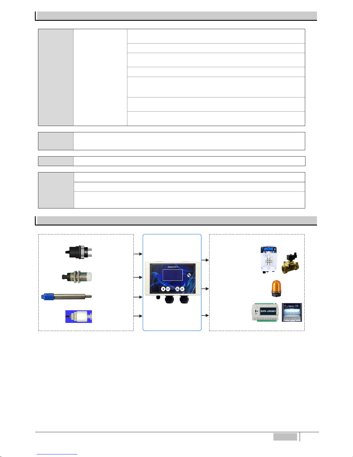
INPUTS / OUTPUTS DIAGRAM FUNCTIONS
INPUTS TO...........
EC
probe
Proximity
switch
Temperature
sensor
Level probe
for chemical
tanks
OUTPUTS TO...........
Set point 1-2
dosing pumps,
solenoid valves or
other equipment
Alarm output
(using Set point 2)
mA ouputs:
data logger:
chart recorder;
dosing pumps
Page 18

18
ENGLISH
INITIAL DISPLAY
NOTES FOR PROGRAMMER: try not to press the keys continuously. First, read the manual before programming or have the
booklet handy so to be sure to perform a correct selection.
IMPORTANT: if keys are not pressed during 60 seconds, controller will display current measurements.
For rapid advancement, keep pressed firmly either one of ◄► keys
When the controller is turned ON there will be displayed at the bottom the latest software upgrade.
Software is subject to revision without further notice.
Controller will get set for measurements and ready to work.
at this point there could be some here are displayed some other messages status such as:
S1 S2 L1 ALARM OVERDOSING FLOW *BASIC MENU* *EXPERT MENU*
which could be ON due to actual measurements, just go ahead with programming.
Display shows pH, Redox mV and Chlorine ppm measurements. If controller has been already programmed, display shows
previously selected set points.
INITIAL DISPLAY
shows measurements according to the K range selected in the next
paragraph.
If the controller has been already programmed, display will show previously
selected programs.
CONTINUOS MEASUREMENT DISPLAY
shows when parameter measurements, function
status and alarm indications.
When the controller is turned ON for the first time, th
ere will be displayed a list of all the
programming function keys which will not appear in the next switching ON operations.
CAREFULLY READ KEY USAGE THEN PRESS
OK to start
For rapid advancement
keep pressed firmly either one of the ◄► keys
Selecting Language
►
◄
The controller has 2 languages: English and
Italian, selected by using the keypad arrows.
Selecting Conductivity (EC) “K” factor
Conductivity EC value automatically adjust itself for various conductivity ranges by adapting the controller to the probes cell costant
“K” characteristic.
Controller covers ranges from cell costant K 1 up to 20.00 mS and even 100.00 mS (latter with graphite sensor electrodes) and
costant K 5 ranges 2.000 μS. Display will show µS values but in case setpoint value exceed 1999 µS, it will show 2.00 mS (decreasing the
value will return to µS reading). Selecting K5 (5.000) range setpoint value 100 µS.
IMPORTANT: the above μS ranges are just indicative: for example a K1 probe can make good measurements below 1000 μS, only
resolution will be less accurate. However the same concept doesn’t apply the other way for high ranges.
Lingua
Italiano
Language
English
ETATRON D.S.
MODEL ESELECT-CD1
Rev. X .X
Page 19

ENGLISH
19
K selections starts from 1.000 and pressing ◄► value can reach up to 20.000 or down to 0,000.
K1 select 1.000
K5 select 5.000
Controller will adapt Measurement and Display resolution according to the type of probe used as shown in page 13;
IMPORTANT: once selected EC probe K factor, ENSURE, to connect the proper Conductivity sensor.
In case, the user wished to change the EC K RANGE, even during operations:
from
∗
BASIC ∗ menu, move to > SETTINGS > CALIBRATION > EC probe K factor
from
∗
EXPERT∗ menu, move to > MAIN MENU > CALIBRAT ION > EC probe K factor
Press ESC to return to MAIN MENU or Press ESC ESC to CONTINUOS MEASUREMENT display.
TEMPERATURE settings
Manual temperature compensation 0÷100°C.
Press ◄► to show the environmental temperature.
Se
lecting AUTO compensation temperature/electrode
measurements, always giving the exact value against the current
temperature.
Press ◄► to show the environmental temperature to calibrate
sensor.
Programming MENU
eSelect-CD1 series allows choosing between:
• BASIC programming: simplified mode for not professional operators
• EXPERT programming: complete programming including functions for a more refined control and results
Once selected the programming menu, Menu and submenus will change accordingly.
To help operator to choose the correct menu here following the main difference between the two menus:
Setpoint 1-2 Setpoint Value - Dosing Mode - Mode ON/OFF or Timed Pulses - Alarm
MIN/MAX - Priming > Calibration > Settings
Setpoint 1-2 Setpoint Value - Dosing Mode - Mode ON/OFF or Timed Pulses Hysteresys - Delay - Temperature correction Alarm MIN/MAX - Overdosing - Startup
Delay - Priming > 4-20mA > Calibration > Settings
Press OK/MENU display shows BASIC mode (default):
►◄
►
Selecting either one of the two menus, will change
the Main Menu programming accordingly.
In case the user wished to change the operating Menu, after the initial selection and even during operations, move to > SETTINGS
menu than go to > PROGRAMMING steps.
►
Press ESC
to return to MAIN MENU or press ESC ESC for CONTINUOS MEASUREMENT display.
After selecting, e.g. choosing EXPERT, at first display will still show Basic but as soon as moving to other steps it will change
to Expert, and vice versa.
CONTROLLER SETTINGS
Temperature
XX°C
CONTROLLER SETTINGS
Temp. Probe
Manual
CONTROLLER SETTINGS
Temp.Probe
Auto
EC METER SETTINGS
EC probe K factor
1.000
CONTROLLER SETTINGS
Programming
BASIC
CONTROLLER SETTINGS
Programming
EXPERT
Select Menu
Settings
Menu
EXPERT
Menu
BASIC
Select Menu
EXPERT
Select Menu
BASIC
Page 20

20
ENGLISH
MAIN MENU > BASIC PROGRAMMING MENU
These are all the steps included in the MAIN MENU loop visualization with BASIC menu programming:
►
◄
►
►
◄
►
Selecting EC probe K range , Setpoint 1 - 2 and Calibration programming will follow range values.
Press OK/MENU
to confirm selection and to approach next submenu.
Press ESC to return to CONTINUOS M EASUREMENT display.
SETPOINT 1 EC CONDUCTIVITY > BASIC MENU
Keep in mind that the value displayed is automatically adjust
ed to the selected
conductivity range cell constant “K” characteristic in previous paragraph SELECTING
CONDUCTIVITY “K” FACTOR
Set point will activate output relays for dosing pumps or other
equipment once selected set-point level is reached. Display will
show µS values but in case setpoint value exceed 1999 µS, it
will show 2.00 mS (decreasing the value will return to µS
reading). Selecting K5 (5.000) range setpoint value 100 µS
Direct mode operation: output is active when measured value is
lower than selected set point thus driving connected equipment.
Reverse mode works the opposite way.
Unit is provided with ON-OFF mode which will activate (or deactivate in case of reverse mode ON)
output relays such as Constant / ON-OFF mode dosing pumps or other On-Off equipment.
* SELECTING MODE “ON-OFF” NEXT PROGRAMMING STEP “ALARM MIN”
*Timed Pulses also known as PWM “pulses with modulation” time/pause allows proportional mode
on each ON-OFF set point activating corresponding pulses on output relay according to measured
value and always relating to the previous hysteresis selected settings. Default activating point at
1000 μS (range 0-20.000 μS DEFAULT); 100 μS (range 0-2000 μS); 0,10 μS (range 0-200 μS);
10000 μS (range 0-200.000 μS)
For more accurate “Timed Pulses” PWM settings, select “Expert” menu from initial settings
* BACK TO SETPOINT PROGRAMMING STEPS FROM EITHER “ON-OFF” OR “TIMED PULSES” MODE
MENU SETPOINT 1
Setpoint Value
100 µS
∗ BASIC MENU ∗
MENU SETPOINT 1
Setpoint Value
1000 µS
∗ BASIC MENU ∗
MENU SETPOINT 1
Mode
Timed Pulses
∗ BASIC MENU ∗
MENU SETPOINT 1
Working Mode
Reverse
∗ BASIC MENU ∗
MENU SETPOINT 1
Working Mode
Direct
∗ BASIC MENU ∗
Select Menu
Setpoint 1 (EC)
MENU SETPOINT 1
Mode
ON/OFF
∗ BASIC MENU ∗
Select Menu
Settings
Select Menu
Calibration
Select Menu
Setpoint 2
Select Menu
Setpoint 1
Page 21
ENGLISH
21
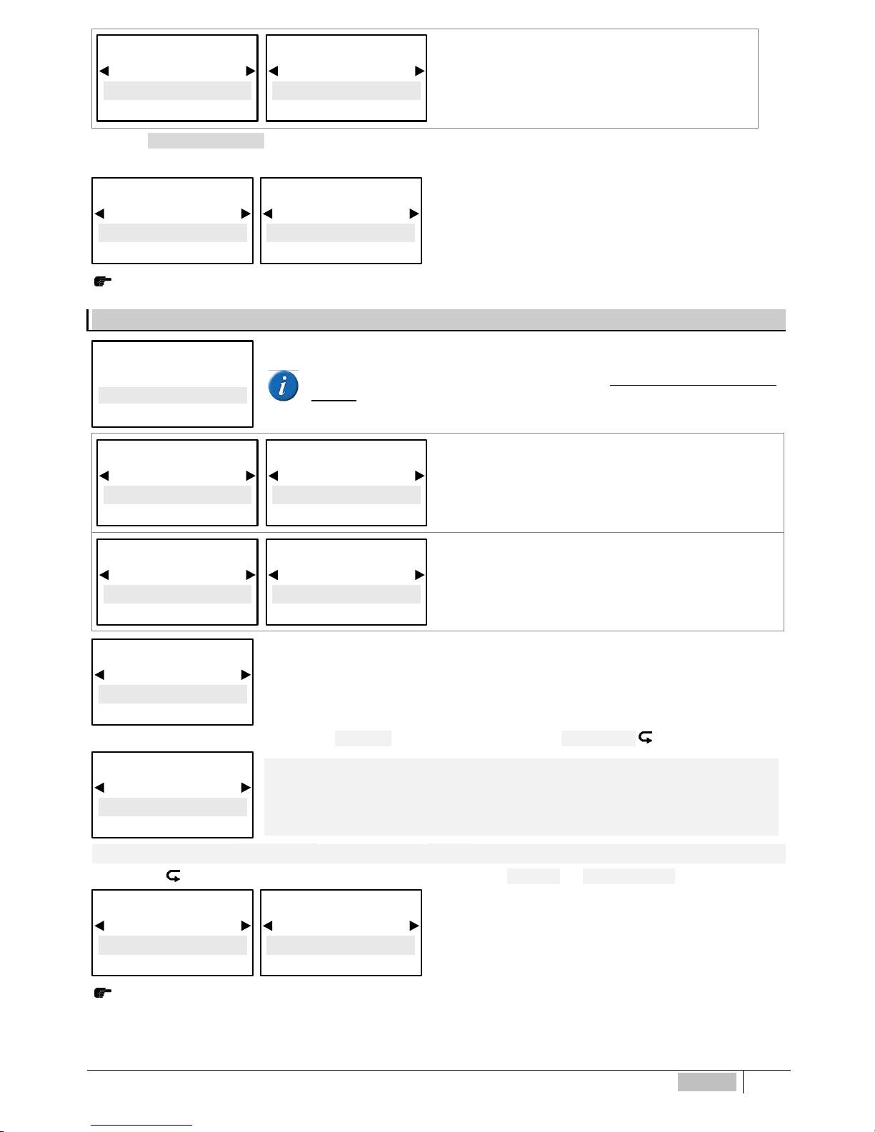
Alarm MIN function selects alarm LOWEST level passed which
alarm relay will be ON.
Alarm MAX function selects alarm HIGH
EST level passed
which alarm relay will be ON.
*Selecting EC probe K range , Alarm Max will show the max value of the selected range, example: selecting range K1 range 20.00
mS, this will be Max alarm value, selecting K5 at the beginning of programming shows 2000 μS
ONLY WHEN USING DOSING PUMPS
Priming function ON will “freeze” the set point value to allow the
dosing pumps to be primed, outputs will not be active.
Press ESC to return to MAIN MENU or Press ESC ESC to C ONTINUOS MEASUREMENT display
SETPOINT 2 EC CONDUCTIVITY > BASIC MENU
Keep in mind that the value displayed is automatically adjusted to the selected onductivity
range cell constant “K” characteristic in previous paragraph SELECTING CONDUCTIVITY “K”
FACTOR. Set point 2 relay can function as Alarm connecting and diving an alarm device or
other equipment (only Alarm High or Low).
Set
point will activate output relays for dosing pumps or other
equipment once selected set-
point level is reached. Display will
show µS values but in case setpoint value exceed 1999 µS, it will
show 2.00 mS (decreasing the value will return to µS reading.
Selecting K5 range setpoint value
100 µS
Reverse mode operation: output is active when measured value is
higher than selected set-point, dosing pump injects chlorine reducer.
Direct mode dosing pump injects chlorine (Oxidant).
Unit is provided with ON-OFF mode which will activate (or deactivate in case of reverse mode ON)
output relays such as Constant / ON-OFF mode dosing pumps or other On-Off equipment.
* SELECTING MODE “ON-OFF” NEXT PROGRAMMING STEP “ALARM MIN”
*Timed Pulses also known as PWM “pulses with modulation” time/pause allows proportional mode on
each ON-OFF set point activating corresponding pulses on output relay according to measured value
and always relating to the previous hysteresis selected settings. Default activating point at 1000 μS
(range 0-20.000 μS DEFAULT); 100 μS (range 0-2000 μS); 0,10 μS (range 0-200 μS); 10000 μS (range
0-200.000 μS)
For more accurate “Timed Pulses” PWM settings, select “Expert” menu from initial settings
* BACK TO SETPOINT PROGRAMMING STEPS FROM EITHER “ON-OFF” OR “TIMED PULSES” MODE
ONLY WHEN USING DOSING PUMPS
Priming function
ON will “freeze” the set point value to allow the
dosing pumps to be primed, outputs will not be active.
Press ESC to return to MAIN MENU or Press ESC ESC to CONTINUOS MEA SUREMENT display
MENU SETPOINT 2
Setpoint Value
100 µS
∗ BASIC MENU ∗
MENU SETPOINT 2
Setpoint Value
1000 µS
∗ BASIC MENU ∗
MENU SETPOINT 2
Mode
Timed Pulses
∗ BASIC MENU ∗
MENU SETPOINT 2
Working Mode
Direct
∗ BASIC MENU ∗
MENU SETPOINT 2
Working Mode
Reverse
∗ BASIC MENU ∗
MENU SETPOINT 1
Priming
ON
∗ BASIC MENU ∗
MENU SETPOINT 1
Priming
OFF
∗ BASIC MENU ∗
MENU SETPOINT 2
Priming
ON
∗ BASIC MENU ∗
MENU SETPOINT 2
Priming
OFF
∗ BASIC MENU ∗
Select Menu
Setpoint 2 (EC)
MENU SETPOINT 2
Mode
ON/OFF
∗ BASIC MENU ∗
MENU SETPOINT 1
Alarm MAX
20.00 mS*
∗ BASIC MENU ∗
MENU SETPOINT 1
Alarm MIN
0 μS*
∗ BASIC MENU ∗
Page 22

22
ENGLISH
SENSOR CALIBRATION > BASIC MENU
IMPORTANT NOTES:
• If there is NO temperature sensor to adjust Temperature move into Expert Menu “Settings > Temperature > Manual”
to change it to required temperature value;
• When calibrate the sensor ensure that the probe electrodes do not touch any surface except the solution;
• Ensure that the sensor is firmly positioned without movements into the solution container;
• Wait the necessary time until calibration measurements are stabilised.
►
Press OK/MENU
to confirm selection and to approach next submenu.
A message will appear before calibration reminding:
We recommend to make a sample solution which matches the required EC value in the system (nor mally the set-point value);
using a good portable EC meter, ensure conductivity levels correspond to the EC requirements. Use a Conductivity sensor
with cell constant according to the selected K factor range (paragraph 8.2) with max cable length of 4 m. After calibration wait
5/10 minutes for measure to stabilise.
Dip EC probe into sample solution previously prepared, wait until measure stabilises.
To modify the value press OK/Menu key, then press ◄► until it shows the sample solution value,
press OK/MENU
to confirm.
Dip EC probe into a buffer solution value which is within the sensor K range wait until measure
stabilises.
To modify the value press OK/MENU
key, then press ◄► until it shows the buffer solution value,
press OK/MENU
to confim.
Press OK/MENU
to confirm selection.
Press ESC
to MAIN MENU
Press ESC ESC
to CONTINUOS MEASUREMENT display.
* It will show the value according to selected range, example: selecting K1 (1.000) range 20.00 mS, this will be Max alarm value, selecting K5
(5.000) at the beginning of programming shows 2000 μS
SETTINGS > BASIC MENU
BASIC programming: simplified mode for not professional operators
EXPERT programming: complete programming including functions
for a more refined control and results.
After selecting, e.g. choosing EXPERT, at first display will still show Basic but as soon as moving to other steps it will change to
Expert, and vice versa.
It adjusts the display save ene
rgy mode backlight level; touching any button will restore full 100%
display operative brightness.
Press ESC to return to MAIN MENU or Press ESC ESC to CONTINUOS MEASUREMENT display.
MEASURE CALIBRATION
Calibrate
1 µS
Select Menu
Calibration
CONTROLLER SETTINGS
Programming
EXPERT
∗ BASIC MENU ∗
CONTROLLER SETTINGS
Programming
BASIC
∗ BASIC MENU ∗
CONTROLLER SETTINGS
Backlight Low lev.
100%
∗ BASIC MENU ∗
Select Menu
Settings
Page 23

ENGLISH
23
LANGUAGE: Choose between English and Italian
Press ESC to return to MAIN MENU or Press ESC ESC to CONTINUOS MEASUREMENT display.
FACTORY SETTINGS
: it restores factory default settings. To be used ONLY when parameters or
measurements are not responding correctly or when user wants to ensure to re-program from zero. Not
to abuse, continuous restoring can affect controller efficiency.
◄
• ◄
•
Once confirmed YES, display will be OFF for 1 second than will return to starting display.
MAIN MENU > EXPERT PROGRAMMING MENU
These are all the steps included in the MAIN MENU loop visualization with EXPERT menu programming:
► ◄
► ◄
►
► ◄
►
*Selecting EC probe K range , Setpoint 1 - 2 and Calibration programming will follow range values.
*Selecting K factor range Setpoint 1 - 2 and Calibration programming will follow selected range values.
Press OK/MENU
to confirm selection and to approach next submenu.
Press ESC to return to CONTINUOS M EASUREMENT display.
SETPOINT 1 EC CONDUCTIVITY > EXPERT MENU
Keep in mind that the value displayed is automatically adjusted to the selected
conductivity range cell constant “K” characteristic in previous paragraph SELECTING
CONDUCTIVITY “K” FACTOR
Set point will activate output relays for dosing pumps or other
equipment once selected set-point level is reached. Display will
show µS values but in case setpoint value exceed 1999 µS, it
will show 2.00 mS (decreasing the value will return to µS
reading). Selecting K5 (5.000) range setpoint value 100 µS
CONTROLLER SETTINGS
Lingua
Italiano
∗ BASIC MENU ∗
CONTROLLER SETTINGS
Language
English
∗ BASIC MENU ∗
MENU SETPOINT 1
Setpoint Value
100 µS
∗ EXPERT MENU ∗
MENU SETPOINT 1
Setpoint Value
1000 µS
∗ EXPERT MENU ∗
Select Menu
Setpoint 1 (EC)
Select Menu
Settings
Select Menu
Calibration
Select Menu
4-20mA
Select Menu
Setpoint 2
Select Menu
Setpoint 1
CONTROLLER SETTINGS
CONFIRM ?
YES
∗ BASIC MENU ∗
CONTROLLER SETTINGS
CONFIRM ?
NO
∗ BASIC MENU ∗
CONTROLLER SETTINGS
Factory Se tt in g s
YES
∗ BASIC MENU ∗
CONTROLLER SETTINGS
Factory Se tt in g s
NO
∗ BASIC MENU ∗
Page 24

24
ENGLISH
Direct mode operation: output is active when measured value is
lower than selected set point thus driving connected equipment.
Reverse mode works the opposite way.
Unit is provided with ON-OFF mode which will activate (or deactivate in case of reverse mode ON)
output relays such as Constant / ON-OFF mode dosing pumps or other On-Off equipment.
* SELECTING MODE “ON-OFF” NEXT PROGRAMMING STEP “HYSTERESIS”
SELECTING MODE “TIMED PULSES” WILL REQUIRE NEXT PARAM ET E RS SET T IN G S
*Timed Pulses also known as PWM “pulses with modulation” time/pause allows proportional mode
on each ON-OFF set point activating corresponding pulses on output relay according to measured
value and always relating to the previous hysteresis selected settings. Default activating point at
1000 μS (range 0-20.000 μS DEFAULT); 100 μS (range 0-2000 μS); 0,10 μS (range 0-200 μS);
10000 μS (range 0-200.000 μS)
EC CONDUCTIVITY TIMED PUL SES PROGRAMMING
Window Width (example with range 2000 μS): pulses are time d ON and OFF according to the
distance from selected set point, programmable, example: if selected set point is 700 μS EC and
measured value is 600 μS, PWM mode will start after reaching 650 μS with Time/Pause pulses
and decreasing the active time while reaching set point value.
*Value shown according to
selected K range.
Cycle Time: PWM mode cycle 60 seconds (programmable): e.g. set point 700 μS, window width
850 μS EC = active time 60 sec / pause time = 0 sec.; at measured value 775 μS EC active time=
30 sec / pause time 30 sec.....and decreasing active time accordingly while reaching set point
value.
Cycle time depends on many variables such as distance from injection point to treating system,
reaction time required, chemical concentration, etc....
Active Time MIN (minimum, programmable): it sets the minimum time in which PWM is active, it
overrules the minimum setting programmed, In case user has selected Active time min 5 sec.,
this will be minimum time of PWM (check page 15, Timed Pulses function).
SELECTING MODE “ON-OFF” NEXT PROGRAM MING STEPS ARE AS FOLLOW ……
NOT AVAILABLE WITH TIMED PULSES MODE
Hysteresis is used to activate or deactivate output relays when selected value is reached. It is
useful when there are too many and/or quick changes, which could damage connected equipment.
Increasing Hysteresis will allow to move away from set point value. *Value shown according to
selected K range.
NOT AVAILABLE WITH TIMED PULSES MODE
Delay time blocks relay outputs to ensure that the outputs are active only when the sensors
measurements are stable thus allowing the best results in terms of chemical balance.
*BACK TO SETPOINT PROGRAMMIN G STEPS FROM EITHER “ON-OFF” OR “TIMED PULSES” MODE
EC alfa factor is the correction factor for conductivity measurement in function of temperature:
EVERY CONDUCT IVITY SEN SOR IS TEMP ERATURE-D EPENDENT. Co nductivity varie s linearly
according to the temperature of the solution. This coefficient normalize the measurement of the
conductivity at the reference temperature of 25° C. For aqueous solutions, this coefficient is
normally 1.9%-2% per °C. Select 0 if you do not want to normalize the reading. Alfa factor ensures
best measurement results and accuracy.
MENU SETPOINT 1
Mode
Timed Pulses
∗ EXPERT MENU ∗
MENU SETPOINT 1
Temp. correction
0.0 %/°C
∗ EXPERT MENU ∗
MENU SETPOINT 1
Active Time MIN
5 sec
∗ EXPERT MENU ∗
MENU SETPOINT 1
Cycle Time
60 sec
∗ EXPERT MENU ∗
MENU SETPOINT 1
Window Width
1000 μS*
∗ EXPERT MENU ∗
MENU SETPOINT 1
Set point Delay
5 sec
∗ EXPERT MENU ∗
MENU SETPOINT 1
Hysteresis
200 μS*
∗ EXPERT MENU ∗
MENU SETPOINT 1
Working Mode
Reverse
∗ EXPERT MENU ∗
MENU SETPOINT 1
Working Mode
Direct
∗ EXPERT MENU ∗
MENU SETPOINT 1
Mode
ON/OFF
∗ EXPERT MENU ∗
Page 25

ENGLISH
25
EVERY CONDUCTIVITY SENSOR IS TEMPERATURE DEPENDENT. Conductivity varies linearly according to the temperature of the
solution. Normally the best measurements are obtained by automatic temperature compensation using PT100 temperature sensor.
Whenever operator DOES NOT have the temperature sensor, we strongly recommend to set use MANUAL temperature programming step.
eSelect-CD1 series allows to choose between:
- MANUAL selecting the buffer solution and/or environmental current temperature (default set at 25°C)
- PT100 or NTC system allowing automatic temperature compensation connecting a temperature probe.
Press ◄► to adjust according current liquid temperature to calibrate sensor.
Alarm MIN function selects alarm LOWEST level passed which
alarm relay will be ON.
Alarm MAX function selects alarm HIGHEST level passed
which alarm relay will be ON.
*Selecting EC probe K range , Alarm Max will show the max value of the selected range, example: selecting range K1 range 20.00 mS,
this will be Max alarm value, selecting K5 at the beginning of programming shows 2000 μS
ONLY WHEN USING DOSING PUMPS
Over dosing time-out alarm selects a period of time for reaching set-point. If set point is not reached
within time, controller will block outputs operations including mA outputs (dosing pump). Alarm is
ON shown on display and will activate relay4 activating an alarm device.
Start-up Delay time “freezes” the relay outputs when switching ON the unit thus allowing sensors to
polarize ensuring correct measurements.
ONLY WHEN USING DOSING PUMPS
Priming function ON will “freeze” the set point value to allow the
dosing pumps to be primed, outputs will not be active.
Press ESC to return to MAIN MENU or Press ESC ESC to CONTINUOS MEASUREMENT display
SETPOINT 2 EC CONDUCTIVITY > EXPERT MENU
Keep in mind that the value displayed is automatically adjusted to selected conductivity
range cell constant “K” characteristic in previous paragraph SELECTING
CONDUCTIVITY “K” FACTOR. Set point 2 relay can function as Alarm connecting and
diving an alarm device or other equipment (only Alarm High or Low).
Set point will activate output relays for dosing pumps or other
equipment once selected set-point level is reached. Display will
show µS values but in case setpoint value exceed 1999 µS, it
will show 2.00 mS (decreasing the value will return to µS
reading). Selecting K5 (5.000) range setpoint value 100 µS
Direct mode operation: output is active when measured value is
lower than selected set point thus driving connected equipment.
Reverse mode works the opposite way.
MENU SETPOINT 1
Alarm MAX
20.00 mS*
∗ EXPERT MENU ∗
MENU SETPOINT 1
Alarm MIN
0 μS*
∗ EXPERT MENU ∗
Select Menu
Setpoint 2 (EC)
MENU SETPOINT 2
Setpoint Value
100 µS
∗ EXPERT MENU ∗
MENU SETPOINT 2
Setpoint Value
1000 µS
∗ EXPERT MENU ∗
MENU SETPOINT 1
Reference Temp.
XX °C
∗ EXPERT MENU ∗
MENU SETPOINT 1
Priming
OFF
∗ EXPERT MENU ∗
MENU SETPOINT 1
Priming
ON
∗ EXPERT MENU ∗
MENU SETPOINT 1
Startup Delay
00:00 h:m
∗ EXPERT MENU ∗
MENU SETPOINT 1
Overdosing
00:00 h:m
∗ EXPERT MENU ∗
MENU SETPOINT 2
Working Mode
Direct
∗ EXPERT MENU ∗
MENU SETPOINT 2
Working Mode
Reverse
∗ EXPERT MENU ∗
Page 26
26
ENGLISH
Unit is provided with ON-OFF mode which will activate (or deactivate in case of reverse mode ON)
output relays such as Constant / ON-OFF mode dosing pumps or other On-Off equipment.
* SELECTING MODE “ON-OFF” NEXT PRO GRAM MING STEP “HYSTERESIS”
SELECTING MODE “TIMED PULSES” WILL REQUIRE NEXT PARAM ET E RS SET T IN G S
*Timed Pulses also known as PWM “pulses with modulation” time/pause allows proportional mode
on each ON-OFF set point activating corresponding pulses on output relay according to measured
value and always relating to the previous hysteresis selected settings. Default activating point at
1000 μS (range 0-20.000 μS DEFAULT); 100 μS (range 0-2000 μS); 0,10 μS (range 0-200 μS);
10000 μS (range 0-200.000 μS)
EC CONDUCTIVITY TIMED PUL SES PROGRAMMING
Window Width (example with range 20000 μS): pulses are timed ON and OFF according to the
distance from selected set point, programmable, example: if selected set point is 700 μS EC and
measured value is 600 μS, PWM mode will start after reaching 650 μS with Time/Pause pulses
and decreasing the active time while reaching set point value.
*Value shown according to
selected K range.
Cycle Time: PWM mode cycle 60 seconds (programmable): e.g. set point 7,00pH, window width
850 μS EC = active time 60 sec / pause time = 0 sec.;
at measured value 775 μS EC active time= 30 sec / pause time 30 sec.....and decreasing active
time accordingly while reaching set point value.
Cycle time depends on many variables such as distance from injection point to treating system,
reaction time required, chemical concentration, etc....
Active Time MIN (minimum, programmable): it sets the minimum time in which PWM is active, it
overrules the minimum setting programmed, In case user has selected Active time min 5 sec.,
this will be minimum time of PWM (check page 15, Timed Pulses function).
SELECTING MODE “ON-OFF” NEXT PROGRAMMING STEPS ARE A S FOL LO W ……
NOT AVAILABLE WITH TIMED PULSES MODE
Hysteresis is used to activate or deactivate output relays when selected value is reached. It is
useful when there are too many and/or quick changes, which could damage connected equipment.
Increasing Hysteresis will allow to move away from set point value. *Value shown according to
selected K range.
NOT AVAILABLE WITH TIMED PULSES MODE
Delay time blocks relay outputs to ensure that the outputs are active only when the sensors
measurements are stable thus allowing the best results in terms of chemical balance.
*BACK TO SETPOINT PROGRAMMIN G STEPS FROM EITHER “ON-OFF” OR “TIMED PULSES” MODE
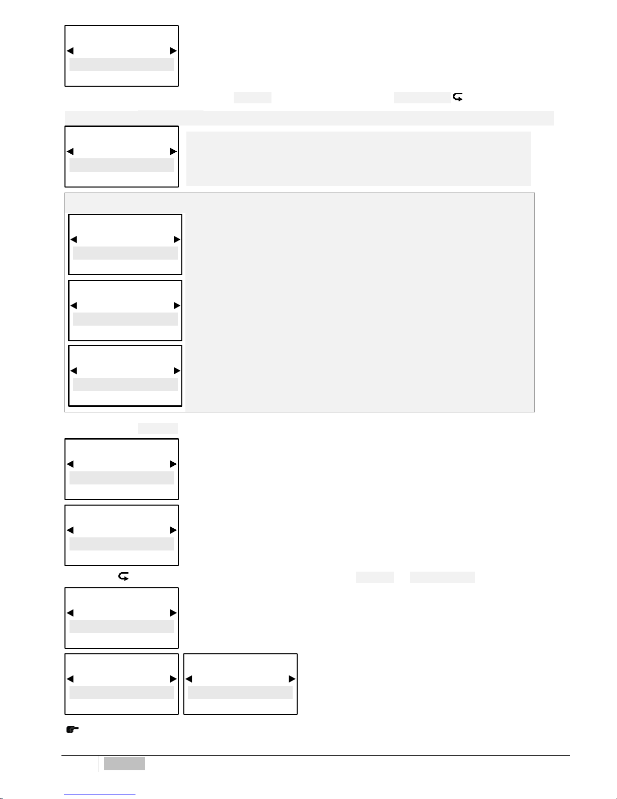
Over dosing time-out alarm selects a period of time for reaching set-point. If set point is not reached
within time, controller will block outputs operations including mA outputs (dosing pump). Alarm is
ON shown on display and will activate relay4 activating an alarm device.
ONLY WHEN USING DOSING PUMPS
Priming function ON will “freeze” the set point value to allow the
dosing pumps to be primed, outputs will not be active
.
Press ESC to return to MAIN MENU or Press ESC ESC to CONTINUOS MEASUREMENT display
MENU SETPOINT 2
Mode
ON/OFF
∗ EXPERT MENU ∗
MENU SETPOINT 2
Mode
Timed Pulses
∗ EXPERT MENU ∗
MENU SETPOINT 2
Active Time MIN
5 sec
∗ EXPERT MENU ∗
MENU SETPOINT 2
Cycle Time
60 sec
∗ EXPERT MENU ∗
MENU SETPOINT 2
Window Width
1000 μS*
∗ EXPERT MENU ∗
MENU SETPOINT 2
Priming
OFF
∗ EXPERT MENU ∗
MENU SETPOINT 2
Priming
ON
∗ EXPERT MENU ∗
MENU SETPOINT 2
Set point Delay
5 sec
∗ EXPERT MENU ∗
MENU SETPOINT 2
Overdosing
00:00 h:m
∗ EXPERT MENU ∗
MENU SETPOINT 2
Hysteresis
200 μS*
∗ EXPERT MENU ∗
Page 27
ENGLISH
27
4-20MA ANALOG CURRENT OUTPUT FUNCTION SELECTION > EXPERT MENU
►
*Selecting Conductivity range, Setpoints and Calibration
programming will follow
selected range values.
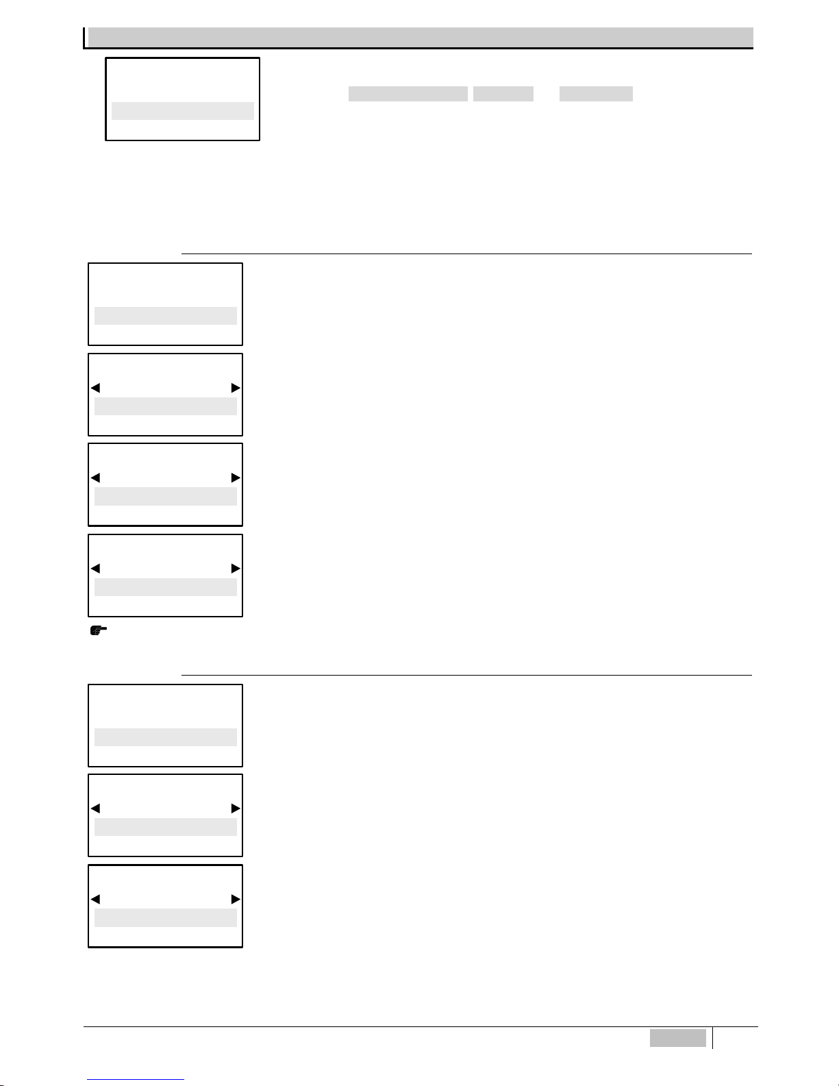
eSelect-CD1 proportional analog 4-20mA follows the option previously selected among the conductivity measuring range.
eSelect-CD1 series mA allows choosing between two functions:
- AUX driving data logger or data recorder or other equipment suitable to work with mA signal.
- DOSING SETPOINT: driving dosing pumps suitable to work with mA signal.
4-20mA EC CONDUCTIVITY > AUX FUNCTION
eSelect-CD1 series proportional analog 4-20mA 2 follows the option previously selected among the
conductivity measuring range.
Proportional analog 4-20 mA outputs Dosing Setpoint follow the set point here following selected
thus driving a dosing pump suitable to process a remote mA current signal.
Select the value corresponding to 4 mA point according to Set point 1 settings.
Keep in mind that the value displayed is automatically adjusted to the selected conductivity range
cell constant “K” characteristic in previous paragraphs.
Select the value corresponding to 20 mA point according to Set point 1 settings.
Press ESC to return to MAIN MENU or Press ESC ESC to CONTINUOS MEASUREMENT display.
4-20mA EC Conductivity > DOSING SETPOINT
eSelect-Cd1 series proportional analog 4-20mA 2 follows the option previously selected among the
conductivity measuring range.
Proportional analog 4-
20 mA outputs Setpoint follow the set point here following selected thus
driving an electrovalve or dosing pump suitable to process a remote mA current signal.
Select the value corresponding to 4 mA point according to Set point 1 settings.
Keep in mind that the value displayed is automatically adjusted to the selected conductivity range
cell constant “K” characteristic in previous paragraphs.
Select Menu
4-20mA
4-20mA SETTINGS
mA Output Mode
Setpoint
∗ EXPERT MENU ∗
4-20mA SETTINGS
Setpoint Value
1000 μS
∗ EXPERT MENU ∗
Select Menu
4-20mA
4-20mA SETTINGS
mA Output Mode
AUX
∗ EXPERT MENU ∗
4-20mA SETTINGS
Measure @4mA
0 μS
∗ EXPERT MENU ∗
4-20mA SETTINGS
Measure @20mA
20.00 mS
∗ EXPERT MENU ∗
Select Menu
4-20mA
Page 28

28
ENGLISH
Direct mode operation, meaning that output is active when
measured value is lower than selected set-
point, connected
dosing pump will be dosing chlorine and vice versa with Reverse
Mode
Window Width: sets the distance from set point at which point 4-20mA mode will start: 4 mA = 0
dosing pump pulse, 20 mA = max dosing pump pulses frequency. Window width depends on many
variables: distance injection point,
reaction time, chemical %, etc.
Over dosing time-out alarm selects a period of time for reaching set-point. If set point is not
reached within time, controller will block outputs operations including mA outputs (dosing pump).
Alarm is ON shown on display and will activate relay4 activating an alarm device.
Press ESC to return to MAIN MENU or Press ESC E SC to CONTINUOS MEASUREMENT display.
SENSOR CALIBRATION > EXPERT MENU
IMPORTANT NOTES:
- if there is NO temperature sensor to adjust Temperature move into Expert Menu “Settings > Temperature
> Manual” to change it to required temperature value;
- when calibrate the sensor ensure that the probe electrodes do not touch any surface except the solution;
- ensure that the sensor is firmly positioned without movements into the solution container;
- wait the necessary time until calibration measurements are stabilised.
►
Press OK/MENU
to confirm selection and to approach next submenu.
A message will appear before calibration reminding:
We recommend to make a sample solution which matches the required EC value in the system (nor mally the set-point value);
using a good portable EC meter, ensure conductivity levels correspond to the EC requirements. Use a Conductivity sensor
with cell constant according to the selected K factor range (paragraph 8.2) with max cable length of 4 m. After calibration wait
5/10 minutes for measure to stabilise.
Dip EC probe into sample solution previously prepared, wait until measure stabilises.
To modify the value press OK/Menu key, then press ◄► until it shows the sample solution value,
press OK/MENU
to confirm.
Dip EC probe into a buffer solution value which is within the sensor K range wait until measure
stabilises.
To modify the value press OK/MENU
key, then press ◄► until i t shows the buffer solution value,
press OK/MENU
to confim.
Press OK/MENU
to confirm selection.
Press ESC
to MAIN MENU
Press ESC ESC
to CONTINUOS MEASUREMENT display.
* It will show the value according to selected range, example: selecting K1 (1.000) range 20.00 mS, this will be Max alarm value, selecting K5
(5.000) at the beginning of programming shows 2000 μS
MEASURE CALIBRATION
Calibrate
0 µS
Select Menu
Calibration
4-20mA SETTINGS
Overdosing
00:00 h:m
∗ EXPERT MENU ∗
4-20mA SETTINGS
Working Mode
Reverse
∗ EXPERT MENU ∗
4-20mA SETTINGS
Working Mode
Direct
∗ EXPERT MENU ∗
4-20mA SETTINGS
Window Width
200 μS
∗ EXPERT MENU ∗
Page 29

ENGLISH
29
SETTINGS > EXPERT MENU
BASIC programming: simplified mode for not professional
operators
EXPERT programming: complete programming including
functions for a more refined control and results.
After selecting, e.g. choosing EXPERT, at first display will still show Basic but as soon as moving to other steps it will change
to Expert, and vice versa.
Flow sensor enabled in case no water into sensor cell holder
(proximity switch will deactivate all outputs ensuring that no
extra chemical is added.
Manual temperature compensation 0÷100°C.
Press ◄► to show the environmental temperature.
Selecting Auto automatic compensation temperature/electrode
measurements, always giving the exact value against the
current temperature.
Press ◄► to show the environmental temperature to
calibrate sensor.
It adjusts the display save energy mode backlight level; touching any button will restore full 100%
display operative brightness.
Press ESC to return to MAIN MENU or Press ESC ESC to CONTINUOS MEASUREMENT display.
FACTORY SETTINGS: it restores factory default settings. To be used ONLY when parameters or
measurements are not responding correctly or when user wants to ensure to re-program from
zero. Not to abuse, continuous restoring can affect controller efficiency.
◄
► ◄
►
Once confirmed YES, display will be OFF for 1 second than will return to starting display.
CONTROLLER SETTINGS
Programming
BASIC
∗ EXPERT MENU ∗
CONTROLLER SETTINGS
Programming
EXPERT
∗ EXPERT MENU ∗
CONTROLLER SETTINGS
CONFIRM ?
YES
∗ EXPERT MENU ∗
CONTROLLER SETTINGS
CONFIRM ?
NO
∗ EXPERT MENU ∗
CONTROLLER SETTINGS
Factory Se tt in g s
YES
∗ EXPERT MENU ∗
CONTROLLER SETTINGS
Factory Se tt in g s
NO
∗ EXPERT MENU ∗
CONTROLLER SETTINGS
Backlight Low lev.
100%
∗ EXPERT MENU ∗
Select Menu
Settings
CONTROLLER SETTINGS
Probe Calibration
XX°C
∗ EXPERT MENU ∗
CONTROLLER SETTINGS
Temp. setting
XX°C
∗ EXPERT MENU ∗
CONTROLLER SETTINGS
Temp. mode
Auto
∗ EXPERT MENU ∗
CONTROLLER SETTINGS
Temp. mode
Manual
∗ EXPERT MENU ∗
CONTROLLER SETTINGS
Flow Sensor
Enabled
∗ EXPERT MENU ∗
CONTROLLER SETTINGS
Flow Sensor
Disabled
∗ EXPERT MENU ∗
Page 30

30
ENGLISH
CONDUCTIVITY SENSORS AND MAINTENANCE
CONDUCTIVITY sensors NOTES
eSelect-CD1 works with simple conductivity 2-electrode open sensors, with AISI 316 and Graphite electrodes.
NOTE FOR CONDUCTIVITY SENSORS
eSelect-CD1 works with simple conductivity 2-electrode open sensors, AISI 316 OR Graphite electrode.
FOR CONDUCTIVITY SENSORS 4 WIRES (with internal temperature sensor): due to the various types on the market, in case
operator wished to use such sensor, please contact ETATRON
service or Local Dealer to get the right configuration for
connecting to terminal board.
eSelect-CD1 is NOT suitable for inductive EC sensors !
eSelect-CD1 automatically adjust itself for various conductivity ranges by adapting the controller to the different probes cell costant “K”
characteristic.
Conductivity measurement are in micro Siemens features 4 K factor ranges (Cell Constant) suitable for:
IMPORTANT: the above μS ranges are just indicative, considering that, for example, a K1 probe can make good measurements below 1000
μS, only resolution will be less accurate. However, the same concept does not apply the other way around to higher ranges.
TEMPERATURE CORRECTION (EC alfa factor)
EC alfa factor is the correction factor for conductivity measurement in function of temperature: EVERY CONDUCTIVITY SENSOR IS
TEMPERATURE-DEPENDENT. Conductivity varies linearly according to the temperature of the solution. This coefficient normalize the
measurement of the conductivity at the reference temperature of 25° C. Alfa factor ensures best measurement results and accuracy.
2% per °C is an average found typical of many water samples with some dissolved solids. Over wide temperature spans (e.g. 0 to 100 °C)
the temperature compensation factor may not remain constant,
CONDUCTIVITY sensors maintenance
Sensor Storage
Short term: Rinse the sensor electrodes in demineralised water; allow drying and storing dry.
Long term: Rinse the sensor electrodes in demineralised water, allow to dry, cover with tip with a plastic shipping cap and store dry.
Monthly Maintenance
A monthly maintenance check is recommended by grab sample calibration since the sensor is typically installed in the process and not easy
to remove. Follow the procedure under calibration by grab sample.
Keep a log of the cell constant at each monthly calibration.
When to clean your sensor
Various factors can affect the physical limits on the liquid and the apparent cell constant; scale, biological growths, oils, wax, gum, etc all
reduce the area for current-carrying liquid. Periodic cleaning of conductivity sensors in continuous use will remove these deposits; restore the
conducting surfaces, controlled cell volume, and thus the cell constant.
Page 31

ENGLISH
31
CONDUCTIVITY sensors range
SCD conductivity probe EC sensor K1
AISI 316 electrodes, PVC body (available PTFE),
1/2” Gm, 4 m cable
SCD conductivity probe EC sensor K5
AISI 316 electrodes, PVC body (available PTFE),
1/2” Gm, 4 m cable
STGCD conductivity probe EC sensor K1 or K5
GRAPHITE electrodes, PTFE body, 1/2” Gm, 4 m cable
SCD graphite conductivity probe has the same wiring
configuration as above probes but electrodes are in
graphite.
Graphite EC sensor K1 is also suitable for 100.000 μS
range.
TROUBLESHOOTING
WARNING: ignoring safety information can endanger life or result in serious injury!
BEWARE: in presence of chlorine gas or a environment saturated with chlorine gas, ensure to lock the power supply of the
chlorine gas dosing equipment; ensure also to secure the power supply to other equipment being part of the plant.
Before working on the unit, disconnect the controller from the mains voltage
MALFUNCTION POSSIBLE CAU SE SOLUTION
1. Display is OFF
No power supply
a. Check electrical connections
b. Check if mains correspond to power supply printed
instrument label.
Internal fuse is blown out
Change the fuse
2. Display measurements don’t
move (there are no changes)
Conductivity levels are NOT stable
Double check levels by means of portable instrument or
colorimetric kit, particularly Temperature reference measure.
Signal from sensor doesn’t change
Repeat sensor calibration and if the problem remains change
the probe
3. Display measurements change
continuously (measuring jumps)
Electrical disturbs from electrical
local network
Check the electrical local network. Check system ground
connection.
Electrical disturbs into the
measuring liquid
Check controller calibration , if controller measures correctly
eliminate electrical disturbs and refer to below point A.
4. It’s not possible to complete
sensor calibration procedure
Buffer solution kit old or
contaminated
Change buffer solution and use portable Kit
Sensor is defective
Check sensor condition (see page 29).
IMPORTANT TESTS in the above cases 2, 3, 4, always test the unit functioning making the following steps:
A. Dismount the unit from the system and mount it into another room or you own lab without connection to other equipment but directly to
local network mains.
B. Recreate into a bucket with fresh water the physical-chemical conditions as in the plant, for pH levels.
C. Program the unit and calibrate sensor.
a . If results are a correct unit functioning, it means there are problems with the systems
b. If problems persist, change sensor with brand new ones: if problem persist, the unit is defective, otherwise use new sensors
RED wire
WHITE wire
Shielded wire / Ground
Probe SCD cable wiring
Page 32

32
ENGLISH
5. Set-point relay doesn’t close
the contact
Set-point value is incorrect
Change set-point value
Set-point “direction” mode is
incorrect
Change set-point function mode, direct or reverse, from the
menu functions
The unit works with universal voltage 100÷250Vac (±10%) or 9÷24Vdc. If the actual voltage is constantly at the limit and/or
lower or higher, or when voltage spikes are much higher than mentioned range, the unit c.a. input is electronically protected
against previously mentioned Voltage fluctuations, above that, controller will not function and pcb must be replaced, contact
manufacturer Customer Service or the local Dealer
Ensure that the system EARTH, in which the controller operates, is properly made, including pipes, other equipment
installed, relays, etc.
TROUBLESHOOTING HINTS FOR CONDUCTIVITY SENSOR
Slow Response typically due to excessive sample line length and low flow, thus producing long sample transport lags. Resolve by adding a
fast-flow loop with the sensor in a short side stream, or by shortening the line. Slow response can also be caused by a build up of dirt in the
sample line. In this case the problem may be alleviated by changing the take-off point or by installing a knock-out pot.
Readings consistently low or spike low characteristic of bubbles in the sample line passing through the sensor or hanging up in the
sensor.
Readings gradually falling the controller can no longer be calibrated properly. This problem is typical of scale or sludge/slime deposits in
the sensor. The sensor may need to be cleaned.
Readings at maximum under all conditions. First verify that controller is displaying conductivity using Conductivity portable controller.
Page 33

Page 34

Note:
Page 35

Page 36

ITALY (BRANCH OFFICE)
ETATRON D.S.
ASIA
ETATRON D.S. PTE Ltd
BRASIL
ETATRON do Brasil
FRANCE
ETATRON FRANCE
Batiment 4 - Hall 406 95520
Osny FRANCE
Phone: +33 (0)1 34 48 77 15
Fax: +33 (0)1 78 76 73 95
UNITED KINGDOM
ETATRON GB
Newlin Business Park
Exchange Road
Lincoln, LN6 3AB UK
Phone +44 (0) 1522 85 23 97
Str. Avram Iancu, nr.34A
407280 Floresti, Cluj,
ROMANIA
Phone +40 264 57 11 88
Fax +40 364 80 82 97
RUSSIAN FEDERATION
DOSING SYSTEMS
ETATRON AMERICA
DILUTION SOLUTIONS Inc
UKRAINE
ETATRON - UKRAINE ltd.
ESPAÑA
ETATRON DOSIFICACION Y
MEDICION S.L.
Ihurrita Bidea, 13 Bajo 25
Polígono Industrial Oiartzun
20180 OIARTZUN
(Guipúzcoa) ESPAÑA
Phone: +34 902 099 321
3-rd Mytishenskaya, 16/2
129626 Moscow RUSSIA
Phone +7 495 787 1459
Fax +7 495 787 1459
Soborna Street, 446 Rivne,
33024 Rivne Region UKRAINE
Phone +380 36 26 10 681
Fax +380 36 26 22 033
2090 Sunnydale Blvd
Clearwater FL 33765
Phone: 727-451-1198
Fax: 727-451-1197
(Asia-Pacific)
Oxley Business Hub, #04-46
Singapore 408729
Phone +65 67 43 79 59
Fax +65 67 43 03 97
Rua Vidal de Negreiros, 108
Bairro Canindé - CEP 03033-050
SÃO PAULO SP
BRASIL
Phone/Fax +55 11 3228 5774
Via Ghisalba, 13
20021 Ospiate di Bollate
(MI) ITALY
Phone +39 02 35 04 588
Fax +39 02 35 05 421
ROMANIA
ETATRON ROMANIA
COD. DMU 000210ML-A (12-2016)
HEAD OFFICE - ITALY
Via dei Ranuncoli, 53 - 00134 ROMA - ITALY
Phone +39 06 93 49 891 - Fax +39 06 93 43 924
email: [email protected] - web: www.etatronds.com
 Loading...