

Etatron DLX-MF/M, DLXB-MF/M Operating Instructions And Maintenance Manual
ITALIANOENGLISH
POMPE DOSATRICI SERIE
DLX-MF/M E DLXB-MF/M
NORME DI INSTALLAZIONE, USO E MANUTENZIONE
■
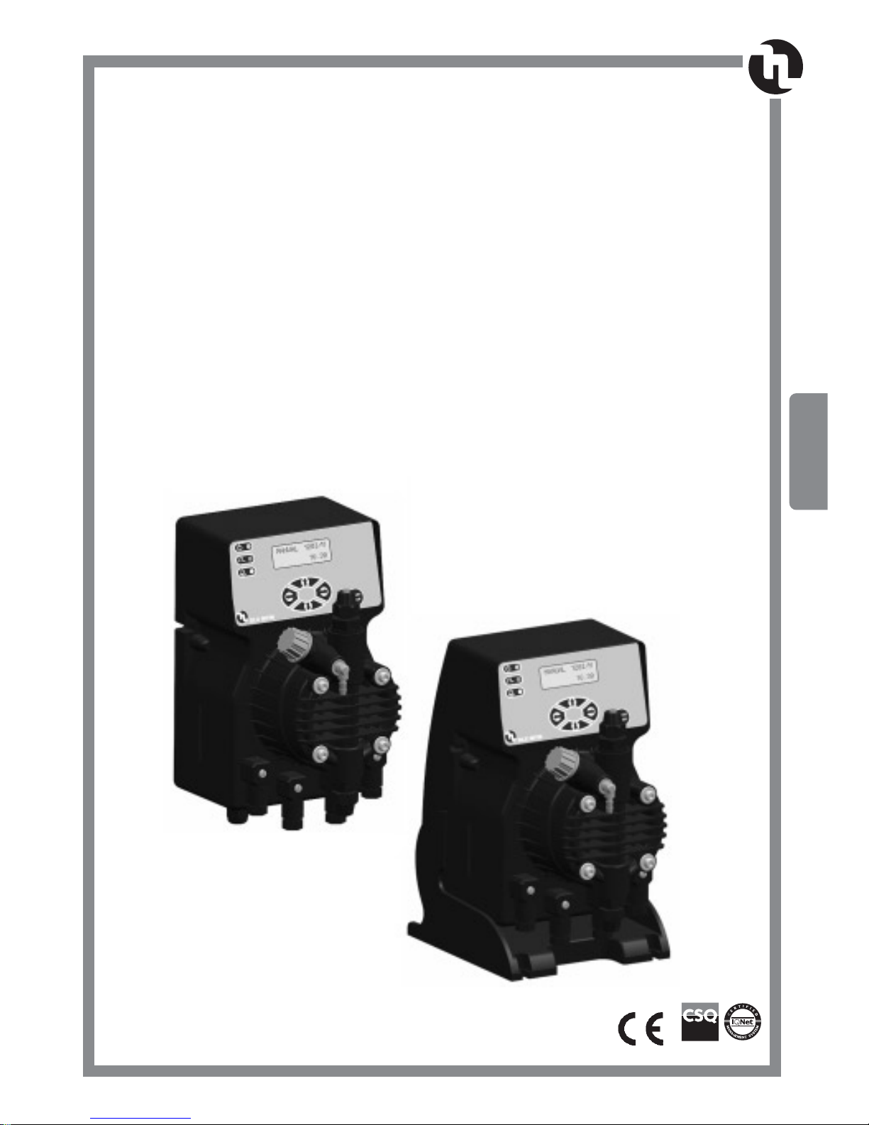
DLX-MF/M AND DLXB-MF/M
SERIES METERING PUMPS
OPERATING INSTRUCTIONS AND MAINTENANCE
UNI EN ISO 9001 - 9190.ETAD

• 27 •
ENGLISH
INDEX
1.0 - HINTS AND WARNING PAG. 28
1.1 - WARNING 28
1.2 - SHIPPING AND TRANSPORTING THE PUMP 28
1.3 - PROPER USE OF THE PUMP 28
1.4 - RISKS 28
1.5 - TOXIC AND/OR DANGEROUS LIQUID DOSAGE 29
1.6 - ASSEMBLING AND DISMANTLING THE PUMP 29
2.0 - DLX MF/M DLXB MF/M MICROCONTROLLER DOSING PUMPS 30
2.1 - OPERATION 30
2.2 - COMMON FEATURES 30-31
2.3 - LIQUID ENDS MATERIALS 32
3.0 - INSTALLATION 33
3.1 - INJECTION VALVE INSTALLATION DIAGRAM 34
4.0 - MAINTENANCE 35
5.0 - HOW TO OPERATE WHEN DOSING SULPHURIC ACID 35
6.0 - MULTIFUNCTIONS DOSING PUMP DLX MF/M - DLXB MF/M SERIES 36
6.1 - PUMP CONTROLS 36
6.2 - TYPICAL INSTALLATION 36
6.3 - ACCESSORIES 36
7.0 - WIRING CONNECTION AND OUTPUT CONNECTOR FUNCTIONS 37
8.0 - DESCRIPTION OF OPERATING MODE 38
8.1 - DESCRIPTION OF ADDITIONAL FEATURES 39
9.0 - TROUBLE SHOOTING COMMON TO DLX - DLXB MF SERIES 40
9.1 - MECHANICAL FAULTS 40
9.2 - ELECTRICAL FAULTS 40-41
9.3 - RESTORATION OF DEFAULT PARAMETERS 41
10.0 - FLOW DIAGRAMS (DISPLAY) 42-52
EXPLODED VIEWS 53-56

• 28 •
1.0 - HINTS AND WARNINGS
Please read the warning notices given in this section very carefully, because they provide important information
regarding safety in installation, use and maintenance of the pump.
• Keep this manual in a safe place, so that it will always be available for further consultation.
• The pump complies with EEC directives No.89/336 regarding "electromagnetic compatibility" and No.73/23
regarding "low voltages", as also the subsequent modification No.93/68.
N.B. The pump has been constructed in accordance with best practice. Both its life and it electrical and
mechanical reliability will be enhanced if it is correctly used and subjected to regular maintenance.
1.1 - WARNING:
Any intervention or repair to the internal parts of the pump must be carried out by qualified and authorized
personnel. The manufacturers decline all responsibility for the consequences of failure to respect this rule.
GUARANTEE: 1 year (the normal wearing parts are excluded, i.e.: valves, nipples, tube nuts, tubing, filter
and injection valve). Improper use of the equipment invalidates the above guarantee. The guarantee is exfactory or authorized distributors.
1.2 - SHIPPING AND TRANSPORTING THE PUMP
The pump should always be moved in a vertical (and never in a horizontal) position. No matter what the means
of transport employed, delivery of the pump, even when free to the purchaser's or the addressee's domicile, is
always at the purchaser's risk. Claims for any missing materials must be made within 10 (ten) days of arrival,
while claims for defective materials will be considered up to the 30th (thirtieth) day following receipt. Return of
pumps or other materials to us or the authorized distributor must be agreed beforehand with the responsible
personnel.
1.3 - PROPER USE OF THE PUMP
• The pump should be used only for the purpose for which it has been expressly designed, namely the dosing
of liquid additives. Any different use is to be considered improper and therefore dangerous.The pump should not
therefore be used for applications that were not allowed for in its design. In case of doubt, please contact our
offices for further information about the characteristics of the pump and its proper use.
The manufactures cannot be held responsible for damage deriving from improper, erroneous or unreasonable
use of the pump.
1.4 - RISKS
• After unpacking the pump, make sure it is completely sound. In case of doubt, do not use the pump and contact qualified personnel. The packing materials (especially bags made of plastics, polystyrene, etc.) should
be kept out of the reach of children: they constitute potential sources of danger.
• Before you connect the pump, make sure that the voltage ratings, etc., correspond to your particular power
supply. You will find these values on the rating plate attached to the pump.
• The electrical installation to which the pump is connected must comply with the standards and good practice rule in force in the country under consideration.
• Use of electrical equipment always implies observance of some basic rules: In particular:
1 - do not touch the equipment with wet or damp hands or feet;
2 - do not operate the pump with bare feet (Example: swimming pool equipment);
3 - do not leave the equipment exposed to the action of the atmospheric agents;
4 - do not allow the pump to be used by children or unskilled individuals without supervision;
• In case of breakdown or improper functioning of the pump, switch off, but do not touch. Contact our technical assistance for any necessary repairs and insist on the use of original spares. Failure to respect this condition could render the pump unsafe for use.
• When you decide to make no further use of an installed pump, make sure to disconnect it from the power
supply.
Before carrying out any service on the item, check:
1. Disconnect the pins from the mains or by means of a two poles switch with 3 mm minimum distance
between the contacts. (Fig. 4).
2. Relieve all the pressure from the pump head and injection tube.
3. Drain or flush all dosing liquid from the pump head. This operation can also be done with the pump disconnected from the plant by turning the pump upside-down for 15 to 30 seconds and without connecting
the tubing to the nipples: if this operation is not possible, dismount and remount the pump head using
the four mounting screws.
In event of possible losses in the hydraulic system of the pump (breakage of the "O" ring gasket, the valves
or the hoses) the pump should immediately be brought to a stop, emptying and depressurizing the delivery
hose while taking all due safety precautions (gloves, goggles, overalls, etc.).

• 29 •
ENGLISH
1.5 - TOXIC AND/OR DANGEROUS LIQUID DOSAGE
To avoid risk from contact with the hazardous liquids or toxic fumes, always adhere to the notes in this instruction manual:
• Follow the instructions of the dosing liquid manufacturer.
• Check the hydraulic part of the pump and use it only if it is in perfect condition.
• Use only the correct materials for the tubing, valves and seals to suit the liquid to be dosed; where possible
shield the tubing with PVC conduit.
• Before disconnecting the metering pump, make sure to flush out and neutralize the pump head with the
proper reagent liquid.
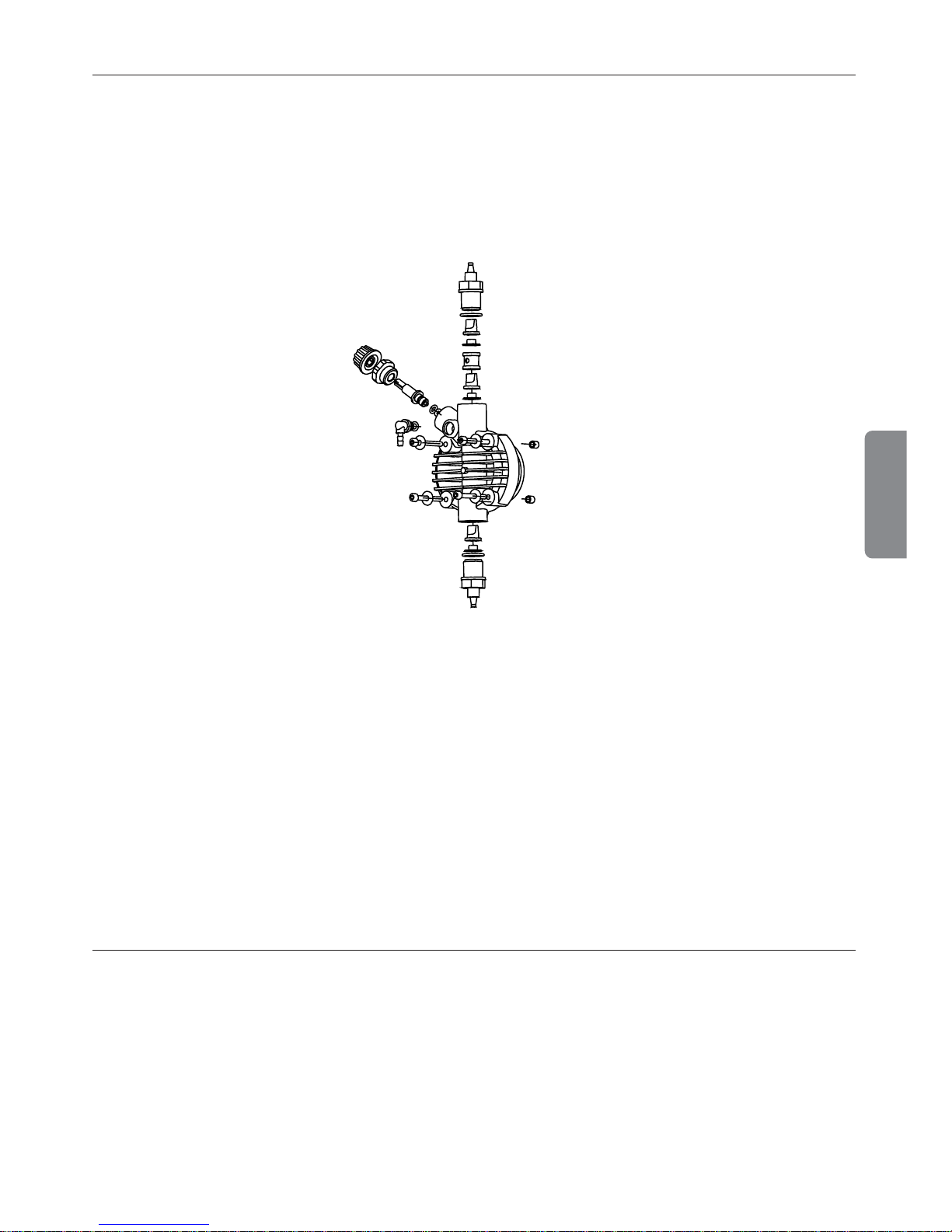
1.6 - ASSEMBLING AND DISMANTLING THE PUMP
1.6.1 - ASSEMBLY
All metering pumps are normally supplied fully assembled. For greater clarity, please consult the exploded view
of the pump appended at the end of the manual, which shows all the pump details and a complete overview of
all the pump components. These drawings are in any case quite indispensable whenever defective parts have
to be re-ordered. For the same purpose, the appendix also contains other drawings showing the hydraulic parts
(pump head and valves).
1.6.2 - DISMANTLEMENT
Proceed as follows before you dismantle the pump or before performing any other operation on it:
1. Disconnect the pins from the mains or by means of a two poles switch with 3 mm minimum distance between
the contacts. (Fig. 4).
2. Relieve all the pressure from the pump head and injection tube.
3. Drain or flush all dosing liquid from the pump head. This operation can also be done with the pump disconnected from the plant by turning the pump upside-down for 15 to 30 seconds and without connecting the
tubing to the nipples: if this operation is not possible, dismount and remount the pump head using the four
mounting screws. (Fig. 11).
This operation calls for special attention, and you should therefore consult the drawings in Appendix and
Chapter
1.4“RISKS” before you commence work.
• 30 •
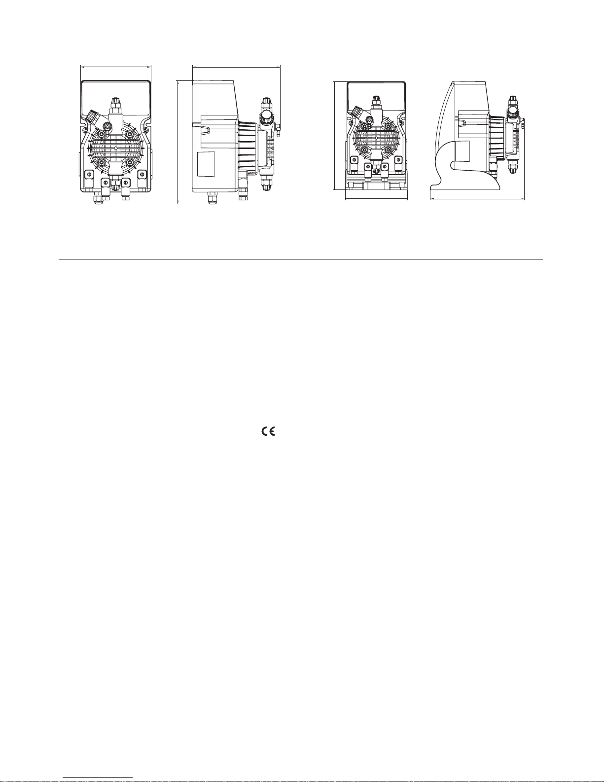
OVERALL DIMENSIONS (Fig. 1)
2.0 - DLX-MF/M AND DLXB-MF/M MICROCONTROLLER DOSING PUMPS
Multifunctions dosing pumps with a microprocessor and a liquid cristal display allows a accurate injection pulses choice.
2.1 - OPERATION
The metering pump is activated by a teflon diaphragm mounted on a piston of an electromagnet.
When the piston of the electromagnet is attracted, a pressure is produced in the pump body with an expulsion
of liquid from the discharge valve. Once the electric impulse is finished a spring brings the piston back to the
initial position, with a recall of liquid through the suction valve.
The operation is simple the pump does not need lubrication, therefore maintenance is reduced almost to zero.
The materials used for the construction of the pump make it particularly suitable for aggressive liquids.
The metering pump has been designed to feed liquids with capacities from 0 to 15 l/h and pressures from 0 to
15 bar (depending on the model selected).
2.2 - COMMON FEATURES
• The products are manufactured according regulation.
• IP 65 protection.
• Antiacid plastic casing.
• Control panel protection assured by an adhesive polyester film, weatherproof and resisting UV ray
• Standard power supply:
230 V a.c.50 Hz single phase.
• Optional power supply:
240 V a.c.50-60 Hz single phase;
110 V a.c. 50-60 Hz single phase.
Upon request: manual stroke lenght adjustment. This control provides accurate flow adjustment. (only DLXB
series)
OPERATING FUNCTIONS:
Manual The pump can be programmed to operate in one of the following ways:
Operating range: 0 – 120 pulses per minute
0 – 120 pulses per hour
0 – 48 pulses per day
1xN When a pulse generating water meter is connected to the pump, every pulse received will
cause the pump to pulse N times. Operating range: 0 – 999 pulses for each contact
0 – 120 pulses per minute
1xN(M) Every pulse from a water meter will cause the pump to pulse N times. While the pump is
pulsing, it still registers all further signals received (M) and translates them into successive pulses. Operating range: 0 – 999 pump pulses (value of N) for each signal received
1 : N Every N number of signals received on the connector, the pump supplies an injection
0-999 pulses for each contact
221 mm
127 mm
192 mm
120 mm
210 mm
150 mm
DLX MF/M (wall mounting) DLXB MF/M (basement mounting)

• 31 •
ENGLISH
mA The pump doses in proportional way to the power signal
Operating range: 0 – 20 mA pulses per minute
0-120 pump pulses per minute
Minimum and maximum cutoff points are adjustable:
Stop/Continue dosing
PPM The pump can dose directly in PPM. User can set the following parameters:
Water meter liter/contacts 0.1, 0.25, 0.5, 1, 2.5, 5, 10, 25, 50, 100, 250, 500, 1000. cc/injection 0.00 - 20.00 Concentration of solution (%) - PPM 0.1 – 20.000
ACCESSORY FUNCTIONS:
FLOW ALARM
A flow sensor (optional) checks the pump flow and activates an alarm should the flow stop
Reference injections 0 - 100 - Max injection difference 0 - 100
RELAY SERVICE Enabled through a flow alarm
Characteristic: 1 pole - 250V a.c. 5A (resistive load)
BUZZER Audible alarm for missed pump pulses can be Enabled / Disabled
CLOCK
Date and time
day/month/year
hour/minutes
Clock holds its settings in the case of power failure of up to 24 hours. Prior to initial use,
pump should be powered for 4-5 Hrs to precharge internal battery
REMOTE CONTROL Ability to control the pump (START / STOP) from normal or reversed polarity remote loca-
tion
TIMER Built-in weekly and daily timer
8 cycles of daily on/off operation. Setting to the minute
LANGUAGE Menu languages choice: Italian / English
Serial line This connector (Pos. 4 - see chapter 7.0) is used only to update the software, although it
RS232 has an input to totally reset the pump only if it goes to permanent block.
Pulses characteristic
• Pulse duration mSec.:80 (user can not change it)
• Max pulses frequency / minute: 100÷120
• Max pulses frequency / hour: 120
• Max pulses frequency / day: 48
Input connectors characteristic
• Min contact duration mSec.:10
• Max contact number / second:40
“mA” characteristic / function
• Ampere meter accuracy: 0,1 mA
• Setting mA (1) SET 1: 4,0 mA
• Setting mA (2) SET 2: 20,0 mA
• Pulses/minute (1) SET 1: 0
• Pulses/minute (2) SET 2: 100÷120
• Below mA (1) SET 1: Stop
• Above mA (2) SET 2: Stop
Remote control
Closing /opening delay contact: 3 seconds - Polarity: Normal
• 32 •
2.3 - LIQUID ENDS MATERIALS
- DIAPHRAGM: PTFE
- PUMP HEAD: Polypropylene; upon request: PVC, 316 Stainless Steel, PTFE, PVDF.
- NIPPLES: polypropylene
- FILTER: polypropylene
- INJECTION NIPPLE: polypropylene
- SUCTION HOSE: PVC - flexible
- DISCHARGE HOSE: polyethylene
- VALVES: “lip”type FPM (Viton®) upon request available in EPDM (Dutral®), NBR, Silycon.
- “Ball Check” VALVES upon request type in SS 316 and Glass PYREX. Available with Spring Return and
“KALRETZ”Valve.
-
SEALS: FPM (Viton®) upon request EPDM (Dutral®), NBR, Silycon, PTFE only for ball checks valves
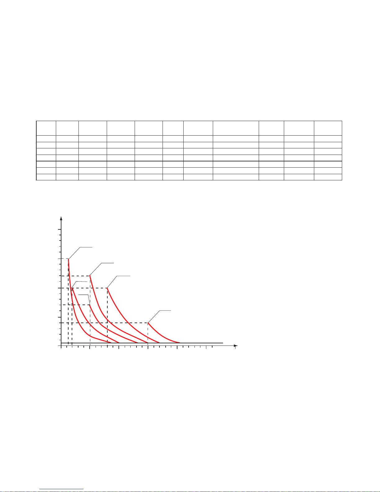
The diagrams of fig. 3 indicate max metering pump flow variation in relation to the working pressure in the
plant; the diagrams also include injection valve losses. I.V.P.
Due to production requirements the technical characteristics of our equipment at maximum ratings can vary
with a tolerance of 5% which must be taken into account when choosing the type of pump.
i.v.p.
bar
20
10
15
5
0
05 1015 20
l/h
02-10
05-07
01-15
05-12
08-10
15-04
Fig. 2
Fig. 3
MAIN FEATURES
Tipo
Type
Portata max
Max flow
Pressione max
Max press
Max imp./min.
Max imp./min.
Dosaggio per imp.
Output per stroke
Corsa
Stroke
Altez. aspiraz.
Suction height
Aliment. elettr. standard
Standard power supply
Potenza ass.
Power consum.
Corrente ass.
Current consum.
Peso netto
Net weight
l/h bar ml mm m
Volts - Hz
Watts Ampere kg
01-15
1 15 120 0.14 0.80 2.0
230 V 50 - 60 Hz
37 0.16 2.3
02-10
2 10 120 0.27 0.80 2.0
230 V 50 - 60 Hz
37 0.16 2.3
05-07
5 07 120 0.70 1.00 2.0
230 V 50 - 60 Hz
37 0.16 2.3
05-12
5 12 120 0,70 1.00 2.0
230 V 50 - 60 Hz
58 0.25 2.9
08-10
8 10 120 1.11 1.40 2.0
230 V 50 - 60 Hz
58 0.25 2.9
15-04
15 04 120 2.08 2.20 2.0
230 V 50 - 60 Hz
58 0.25 2.9
• 33 •
ENGLISH
3.0 - INSTALLATION
a. - Install the pump in a dry place and well away from sources of heat and, in any case, at environmental tem-
peratures not exceeding 40°C. The minimum operating temperature depends on the liquid to be pumped,
bearing in mind that it must always remain in a liquid state.
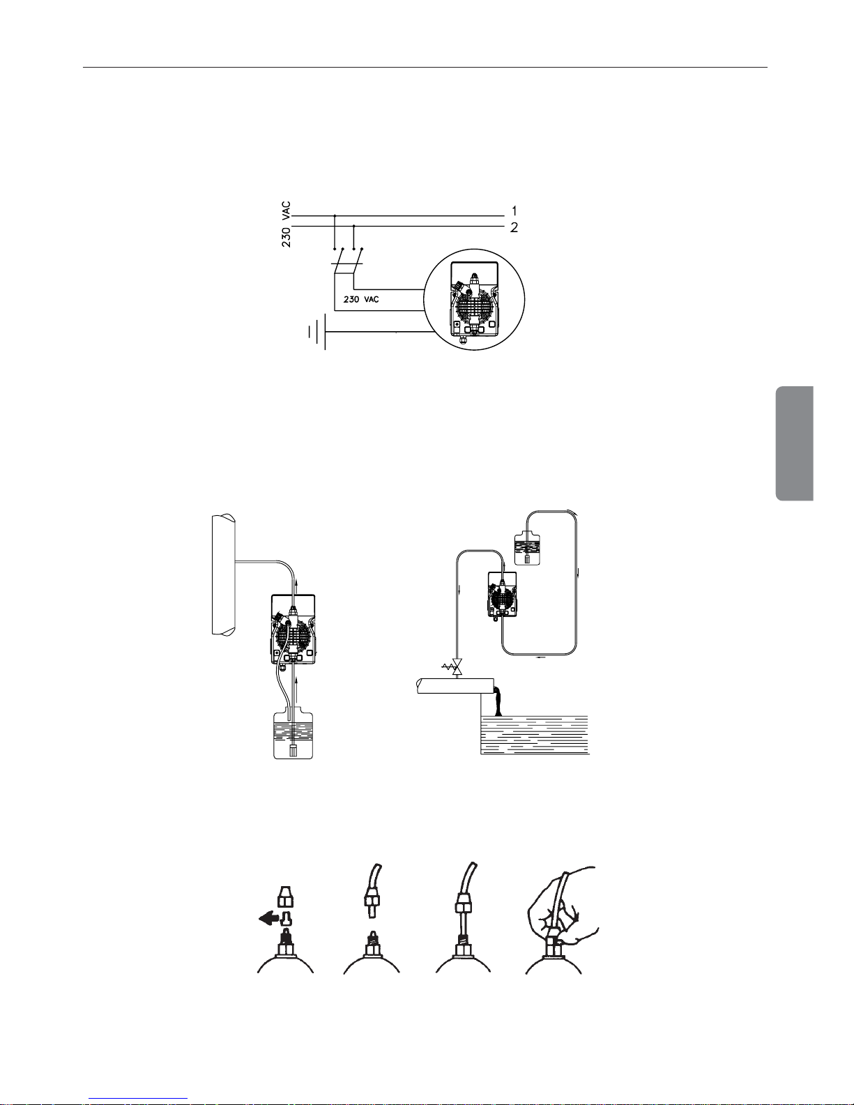
b. - Carefully observe the regulations in force in the various countries as regards electrical installations (Fig.4).
When the supply cable is devoid of a plug, the equipment should be connected to the supply mains by
means of a two-poles switch having a minimum distance of 3 mm between the contacts. Before accessing any of the electrical parts, make sure that all the supply circuits are open.
Fig. 4
c.- Locate the pump as shown in fig. 5 bearing in mind that it may be installed either below or above the level
of the liquid to be dosed, though the level difference should not exceed 2 meters. When the process plant in
which the pump is installed is operating at atmospheric pressure (no back pressure) and the chemical tank
is situated above the plant (Fig. 6), the condition of the injection valve should be checked at regular intervals, because excessive wear and tear could cause additive to drip into the plant even when the pump is shut
down. If the problem persist, install a properly calibrate
counter-pressure valve (C) between injection point
and the valve. In the case of liquids that generate aggressive vapours, do not install the pump above the
storage tank unless the latter is hermetically sealed.
d. - The discharge nipple will always remain in the upper part of the pump. The suction nipple, which serves to
attach the hose (with filter) leading into the chemical tank, will therefore always be situated in the lower part
of the pump.
Fig. 7
e. - Remove the protection caps from the two nipples, slide the hoses over the connectors, pushing them right
home, and then fix them with appropriate tube nuts. (Fig. 7).
Fig. 6
Fig. 5
C
BLUE
BROWN
YELLOW/GREEN

• 34 •
Fig. 8
Whenever the pump is dismantled from the pipework, you will be well advised to replace the caps on the
connectors to avoid residual liquid being spilled. Before attaching the delivery hose to the plant, prime the
metering pump by going through the sequence shown in Fig. 8. Before finalizing the installation of the discharge hose, make sure that the pump strokes will not cause it to move and bump into rigid bodies. In case
of priming difficulties, use a normal syringe to suck liquid from the discharge nipple while the pump is in
operation, continuing until you actually see the liquid rise in the syringe. Use a short length of suction hose
to connect the syringe to the discharge nipple. In case of a pump equipped with an air bleed valve, unscrew
the air relief valve B up to all the air in the pump head will be out.
f. - Try to keep both the suction and discharge hose as straight as possible, avoiding all unnecessary bends.
g. - Select the most appropriate injection point on a pipe of the plant to be treated and there fit a 3/8" female gas
thread connector (similar to BSPm). This connector is not supplied with the pump. Screw the injection valve
to the gas connector, inserting a gasket as shown in Fig. 9. Then connect the discharge hose to the conical
connector on the injection valve and fix it with the supplied tube nut G. The injection valve also acts as no
return valve by means of a cylinder sleeve (elastomer, standard supplied in Viton).
N.B. The sleeve D must not be removed.
3.1 - INJECTION VALVE INSTALLATION
DIAGRAM Fig. 9
A
- Pipework
C - Injection valve
M - Conical connector for attaching the
discharge hose
N - 3/8" female steel gas thread connector
G - Hose tube nut
T - Polyethylene hose
D - Cylinder sleeve (no return valve)
BBB
Fig. 9
• 35 •
ENGLISH
4.0 - MAINTENANCE
1. Periodically check the chemical tank level to avoid the pump operating without liquid. This would not dam-
age the pump, but may damage the process plant due to lack of chemicals.
2. Check the pump operating condition at least every 6 months, pump head position, screws, bolts and seals;
check more frequently where aggressive chemicals are pumped, especially:
- pulse and power L.E.D.;
- the additive concentration in the pipework; a reduction of this concentration could be caused by the wearing of the valves, in which case they need to be replaced (Fig. 10) or by the clogging of the filter which then
has to be cleaned as in point 3 here below.
Fig. 10
3. The Company suggests periodically cleaning off the hydraulic parts (valves and filter). We cannot say how
often this cleaning should be done as it depends on the type of application, we also cannot suggest what
cleaning agent to use as this will depend on the additive used.
Operating suggestions when dosing sodium hypochlorite (most frequent case):
a- disconnect the pins from the mains or by means of a onnipolar switch with 3 mm minimum distance between
the contact.
b- disconnect discharge hose from pipework;
c- remove the suction hose (with filter) from the tank and dip it into clean water;
d- switch on the metering pump and let it operate with water for 5 to 10 minutes;
e - switch OFF the pump, dip the filter into a hydrochloric acid solution and wait until the acid finishes
cleaning;
f- switch ON the pump again and operate it with hydrochloric acid for 5 minutes in a closed-circuit, with
suction and discharge hose dipped into the same tank;
g - repeat the operation with water;
h - re-connect the metering pump to the pipework.
5.0 - HOW TO OPERATE WHEN DOSING SULPHURIC ACID
In this case it is essential to bear in mind the following:
1. replace PVC crystal suction hose with polyethilene discharge hose;
2. empty any residual water from the pump head beforehand.
Warning: if the water mixes with sulphuric acid it can produce a large quantity of gas with consequent overheating of the area causing damage to valves and pump head.
This operation can also be done with the pump disconnected from the plant by turning the pump upside-down
for 15 to 30 seconds and without connecting the hose to the nipples; if impossible, dismount and remount the
pump head (Fig. 10) using the four mounting screws.
 Loading...