

Etatron DLX-pH/M SERIES, DLXB-pH/M SERIES, DLX-Rx/M SERIES, DLXB-Rx/M SERIES Operating Instructions And Maintenance Manual
ENGLISH
POMPE DOSATRICI SERIE
DLX & DLXB-pH/M • DLX & DLXB-Rx/M
NORME DI INSTALLAZIONE, USO E MANUTENZIONE
■
DLX & DLXB-pH/M • DLX & DLXB-Rx/M
SERIES METERING PUMPS
OPERATING INSTRUCTIONS AND MAINTENANCE
UNI EN ISO 9001:2000
9190.ETAD

• 17 •
ENGLISH
INDEX
1.0 - HINTS AND WARNING PAG. 18
1.1 - WARNING 18
1.2 - SHIPPING AND TRANSPORTING THE PUMP 18
1.3 - PROPER USE OF THE PUMP 18
1.4 - RISKS 18
1.5 - TOXIC AND/OR DANGEROUS LIQUID DOSAGE 19
1.6 - ASSEMBLING AND DISMANTLING THE PUMP 19
2.0 - DLX AND DLXB SERIES METERING PUMPS 20
2.1 - OPERATION 20
2.2 - COMMON FEATURES 20
2.3 - LIQUID ENDS MATERIALS 21
3.0 - INSTALLATION 22
3.1 - INJECTION VALVE INSTALLATION DIAGRAM 23
3.2 - WIRING CONNECTION AND OUTPUT CONNECTOR FUNCTIONS 24
3.3 - MANUAL STROKE LENGHT ADJUSTMENT 24
4.0 - MAINTENANCE 25
5.0 - HOW TO OPERATE WHEN DOSING SULPHURIC ACID 25
6.0 - MICROCONTROLLED METERING PUMP WITH pH CONTROLLER 26
6.1 - PUMP CONTROLS 26
6.2 - TYPICAL INSTALLATION 26
6.3 - ACCESSORIES 26
6.4 - LEVEL CONTROL 27
6.5 - COMMISSIONING THE PUMPS 27
6.6 - SET POINT REGULATION 27
6.7 - ACID OR ALKALINE DOSING 27
6.8 - PROPORTIONAL FUNCTIONING 27
6.9 - FUNCTIONS 27
6.10 - ACTIVATION/DISACTIVATION OF THE FUNCTIONS 28
7.0 - MICROCONTROLLED METERING PUMP WITH pH CONTROLLER 29
7.1 - PUMP CONTROLS 29
7.2 - TYPICAL INSTALLATION 29
7.3 - ACCESSORIES 29
7.4 - LEVEL CONTROL 30
7.5 - COMMISSIONING THE PUMPS 30
7.6 - SET POINT REGULATION 30
7.7 - OXIDATIVE OR REDUCING DOSING 30
7.8 - PROPORTIONAL FUNCTIONING 30
7.9 - FUNCTIONS 30
7.10 - ACTIVATION/DISACTIVATION OF THE FUNCTIONS 31
8.0 - TROUBLE SHOOTING COMMON TO DLX - DLXB SERIES PUMPS 32
8.1 - MECHANICAL FAULTS 32
8.2 - ELECTRICAL FAULTS 32
9.0 - ELECTRODE HOLDERS 32
10.0 - ELECTRODE CLEANING AND MAINTENANCE 32
EXPLODED VIEWS 33-36

• 18 •
1.0 - HINTS AND WARNINGS
Please read the warning notices given in this section very carefully, because they provide important information
regarding safety in installation, use and maintenance of the pump.
• Keep this manual in a safe place, so that it will always be available for further consultation.
• The pump complies with EEC directives No.89/336 regarding "electromagnetic compatibility" and No.73/23
regarding "low voltages", as also the subsequent modification No.93/68.
N.B. The pump has been constructed in accordance with best practice. Both its life and it electrical and
mechanical reliability will be enhanced if it is correctly used and subjected to regular maintenance.
1.1 - WARNING:
Any intervention or repair to the internal parts of the pump must be carried out by qualified and authorized
personnel. The manufacturers decline all responsibility for the consequences of failure to respect this rule.
GUARANTEE: 1 year (the normal wearing parts are excluded, i.e.: valves, nipples, tube nuts, tubing, filter
and injection valve). Improper use of the equipment invalidates the above guarantee. The guarantee is exfactory or authorized distributors.
1.2 - SHIPPING AND TRANSPORTING THE PUMP
The pump should always be moved in a vertical (and never in a horizontal) position. No matter what the means
of transport employed, delivery of the pump, even when free to the purchaser's or the addressee's domicile, is
always at the purchaser's risk. Claims for any missing materials must be made within 10 (ten) days of arrival,
while claims for defective materials will be considered up to the 30th (thirtieth) day following receipt. Return of
pumps or other materials to us or the authorized distributor must be agreed beforehand with the responsible
personnel.
1.3 - PROPER USE OF THE PUMP
• The pump should be used only for the purpose for which it has been expressly designed, namely the dosing
of liquid additives. Any different use is to be considered improper and therefore dangerous.The pump should not
therefore be used for applications that were not allowed for in its design. In case of doubt, please contact our
offices for further information about the characteristics of the pump and its proper use.
The manufactures cannot be held responsible for damage deriving from improper, erroneous or unreasonable
use of the pump.
1.4 - RISKS
• After unpacking the pump, make sure it is completely sound. In case of doubt, do not use the pump and contact qualified personnel. The packing materials (especially bags made of plastics, polystyrene, etc.) should
be kept out of the reach of children: they constitute potential sources of danger.
• Before you connect the pump, make sure that the voltage ratings, etc., correspond to your particular power
supply. You will find these values on the rating plate attached to the pump.
• The electrical installation to which the pump is connected must comply with the standards and good practice rule in force in the country under consideration.
• Use of electrical equipment always implies observance of some basic rules: In particular:
1 - do not touch the equipment with wet or damp hands or feet;
2 - do not operate the pump with bare feet (Example: swimming pool equipment);
3 - do not leave the equipment exposed to the action of the atmospheric agents;
4 - do not allow the pump to be used by children or unskilled individuals without supervision;
• In case of breakdown or improper functioning of the pump, switch off, but do not touch. Contact our technical assistance for any necessary repairs and insist on the use of original spares. Failure to respect this condition could render the pump unsafe for use.
• When you decide to make no further use of an installed pump, make sure to disconnect it from the power
supply.
Before carrying out any service on the item, check:
1. Disconnect the pins from the mains or by means of a two poles switch with 3 mm minimum distance
between the contacts. (Fig. 4).
2. Relieve all the pressure from the pump head and injection tube.
3. Drain or flush all dosing liquid from the pump head. This operation can also be done with the pump disconnected from the plant by turning the pump upside-down for 15 to 30 seconds and without connecting
the tubing to the nipples: if this operation is not possible, dismount and remount the pump head using
the four mounting screws (Fig. 12).
In event of possible losses in the hydraulic system of the pump (breakage of the "O" ring gasket, the valves
or the hoses) the pump should immediately be brought to a stop, emptying and depressurizing the delivery
hose while taking all due safety precautions (gloves, goggles, overalls, etc.).

• 19 •
ENGLISH
1.5 - TOXIC AND/OR DANGEROUS LIQUID DOSAGE
To avoid risk from contact with the hazardous liquids or toxic fumes, always adhere to the notes in this instruction manual:
• Follow the instructions of the dosing liquid manufacturer.
• Check the hydraulic part of the pump and use it only if it is in perfect condition.
• Use only the correct materials for the tubing, valves and seals to suit the liquid to be dosed; where possible
shield the tubing with PVC conduit.
• Before disconnecting the metering pump, make sure to flush out and neutralize the pump head with the
proper reagent liquid.
1.6 - ASSEMBLING AND DISMANTLING THE PUMP
1.6.1 - ASSEMBLY
All metering pumps are normally supplied fully assembled. For greater clarity, please consult the exploded view
of the pump appended at the end of the manual, which shows all the pump details and a complete overview of
all the pump components. These drawings are in any case quite indispensable whenever defective parts have
to be re-ordered. For the same purpose, the appendix also contains other drawings showing the hydraulic parts
(pump head and valves).
1.6.2 - DISMANTLEMENT
Proceed as follows before you dismantle the pump or before performing any other operation on it:
1. Disconnect the pins from the mains or by means of a two poles switch with 3 mm minimum distance between
the contacts. (Fig. 4).
2. Relieve all the pressure from the pump head and injection tube.
3. Drain or flush all dosing liquid from the pump head. This operation can also be done with the pump disconnected from the plant by turning the pump upside-down for 15 to 30 seconds and without connecting the
tubing to the nipples: if this operation is not possible, dismount and remount the pump head using the four
mounting screws. (Fig. 12).
This operation calls for special attention, and you should therefore consult the drawings in Appendix and
Chapter
1.4“RISKS” before you commence work.

• 20 •
OVERALL DIMENSIONS (Fig. 1)
2.0 - DLX AND DLXB SERIES METERING PUMPS
2.1 - OPERATION
The metering pump is activated by a teflon diaphragm mounted on a piston of an electromagnet.
When the piston of the electromagnet is attracted, a pressure is produced in the pump body with an expulsion
of liquid from the discharge valve. Once the electric impulse is finished a spring brings the piston back to the
initial position, with a recall of liquid through the suction valve.
The operation is simple the pump does not need lubrication, therefore maintenance is reduced almost to zero.
The materials used for the construction of the pump make it particularly suitable for aggressive liquids.
The metering pump has been designed to feed liquids with capacities from 0 to 20 l/h and pressures from 0 to
15 bar (depending on the model selected).
2.2 - COMMON FEATURES
• The products are manufactured according regulation.
• IP 65 protection.
• Antiacid plastic casing.
• Control panel protection assured by an adhesive polyester film, weatherproof and resisting UV ray
• Standard power supply:
230 V a.c.50 Hz single phase.
• Optional power supply:
240 V a.c.50-60 Hz single phase;
110 V a.c. 50-60 Hz single phase.
Upon request: manual stroke lenght adjustment. This control provides accurate flow adjustment. (only DLXB
series)
221 mm
127 mm
192 mm
120 mm
210 mm
150 mm
DLX (wall mounting) DLXB (basement mounting)
• 21 •
ENGLISH
2.3 - LIQUID ENDS MATERIALS
- DIAPHRAGM: PTFE
- PUMP HEAD: Polypropylene; upon request: PVC, 316 Stainless Steel, PTFE, PVDF.
- NIPPLES: polypropylene
- FILTER: polypropylene
- INJECTION NIPPLE: polypropylene
- SUCTION HOSE: PVC - flexible
- DISCHARGE HOSE: polyethylene
- VALVES: “lip”type FPM (Viton®) upon request available in EPDM (Dutral®), NBR, Silycon.
- “Ball Check” VALVES upon request type in SS 316 and Glass PYREX. Available with Spring Return and
“KALREZ”Valve.
-
SEALS: FPM (Viton®) upon request EPDM (Dutral®), NBR, Silycon, PTFE only for ball checks valves
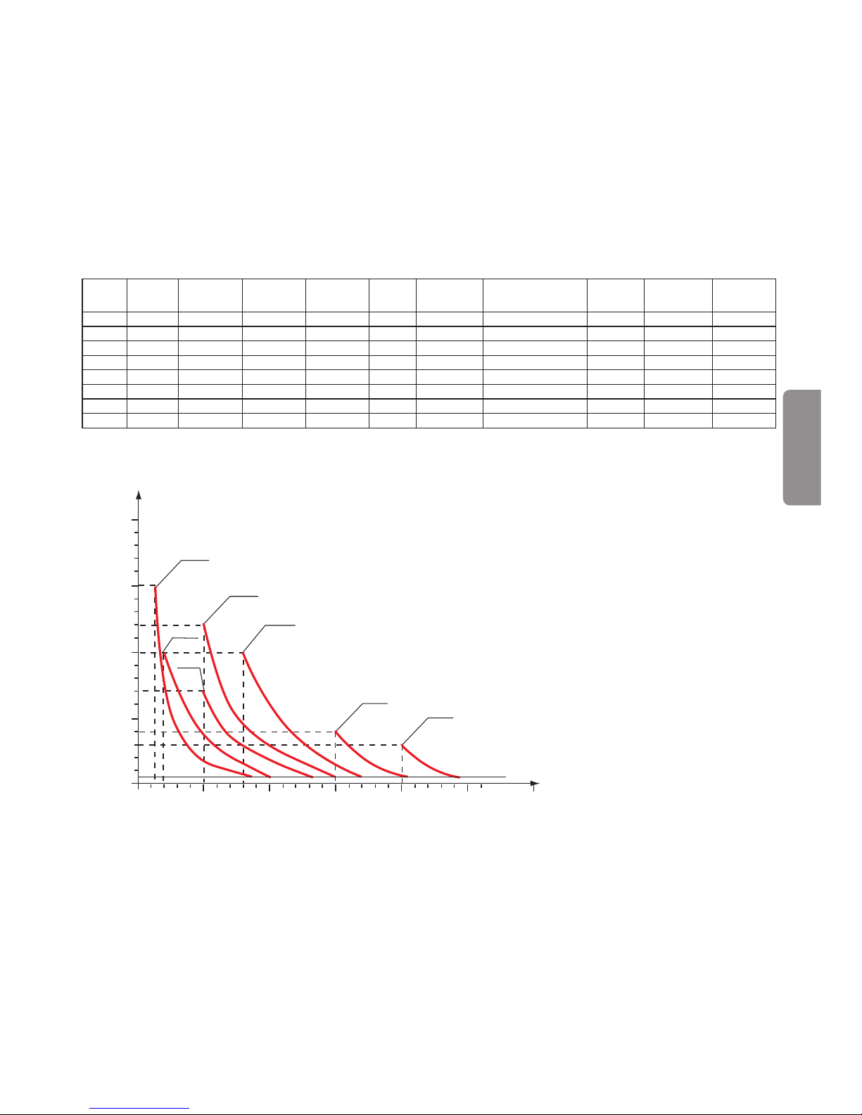
The diagrams of fig. 3 indicate max metering pump flow variation in relation to the working pressure in the
plant; the diagrams also include injection valve losses. I.V.P.
Due to production requirements the technical characteristics of our equipment at maximum ratings can vary
with a tolerance of 5% which must be taken into account when choosing the type of pump.
i.v.p.
bar
20
10
15
5
0
05 1015 20
l/h
2-10
5-7
1-15
5-12
8-10
15-4
20-3
Fig. 2
MAIN FEATURES
Fig. 3
Tipo
Type
Portata max
Max flow
Pressione max
Max press
Max imp./min.
Max imp./min.
Dosaggio per imp.
Output per stroke
Corsa
Stroke
Altez. aspiraz.
Suction height
Aliment. elettr. standard
Standard power supply
Potenza ass.
Power consum.
Corrente ass.
Current consum.
Peso netto
Net weight
l/h bar ml mm m
Vol ts - Hz
Watts Ampere kg
1-15
1 15 120 0.14 0.80 2.0
230 V 50 - 60 Hz
37 0.16 2.3
2-10
2 10 120 0.27 0.80 2.0
230 V 50 - 60 Hz
37 0.16 2.3
5-7
5 7 120 0.70 1.00 2.0
230 V 50 - 60 Hz
37 0.16 2.3
5-12
5 12 120 0,70 1.00 2.0
230 V 50 - 60 Hz
58 0.25 2.9
8-10
8 10 120 1.11 1.40 2.0
230 V 50 - 60 Hz
58 0.25 2.9
15-4
15 4 120 2.08 2.20 2.0
230 V 50 - 60 Hz
58 0.25 2.9
20-3
20 3 120 2.60 2.20 2.0
230 V 50 - 60 Hz
58 0.25 2.9
• 22 •
3.0 - INSTALLATION
a. - Install the pump in a dry place and well away from sources of heat and, in any case, at environmental tem-
peratures not exceeding 40°C. The minimum operating temperature depends on the liquid to be pumped,
bearing in mind that it must always remain in a liquid state.
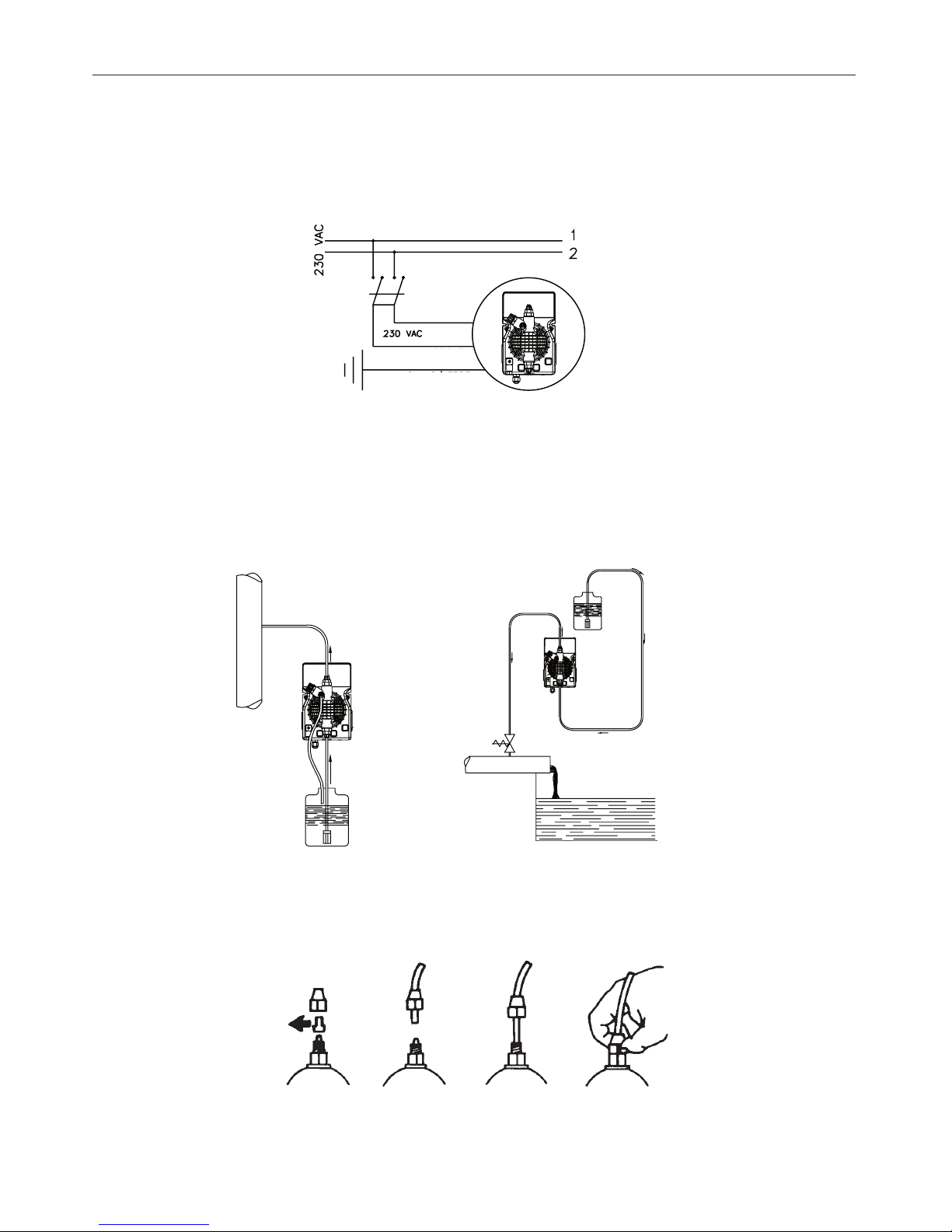
b. - Carefully observe the regulations in force in the various countries as regards electrical installations (Fig.4).
When the supply cable is devoid of a plug, the equipment should be connected to the supply mains by
means of a two-poles switch having a minimum distance of 3 mm between the contacts. Before accessing any of the electrical parts, make sure that all the supply circuits are open.
Fig. 4
c.- Locate the pump as shown in fig. 5 bearing in mind that it may be installed either below or above the level
of the liquid to be dosed, though the level difference should not exceed 2 meters. When the process plant in
which the pump is installed is operating at atmospheric pressure (no back pressure) and the chemical tank
is situated above the plant (Fig. 6), the condition of the injection valve should be checked at regular intervals, because excessive wear and tear could cause additive to drip into the plant even when the pump is shut
down. If the problem persist, install a properly calibrate
counter-pressure valve (C) between injection point
and the valve. In the case of liquids that generate aggressive vapours, do not install the pump above the storage tank unless the latter is hermetically sealed.
d. - The discharge nipple will always remain in the upper part of the pump. The suction nipple, which serves to
attach the hose (with filter) leading into the chemical tank, will therefore always be situated in the lower part
of the pump.
Fig. 7
e. - Remove the protection caps from the two nipples, slide the hoses over the connectors, pushing them right
home, and then fix them with appropriate tube nuts. (Fig. 7).
Fig. 6
Fig. 5
C
BLUE
BROWN
YELLOW/GREEN
 Loading...