

Page 1

CPC Series
Conditioned Power Center
RoHS Compliant
Conditioned Power Center
1
Page 2

SM5505 - March 1, 2006—Rev. A
2
Conditioned Power Center
Page 3

Table of Contents
Caution Notice...............................................................................................................5
Section 1-General .........................................................................................................6
Section 2 – Safety
Section 3 – Product Overview
Section 4 – Preparation
Section 5 – Installation
Section 6 - Operation
Section 7 - Options
2.1 ANSI Warning Notices ..............................................................................7
2.2 Inherent Hazards.......................................................................................7
2.3 Alerts and Labels.......................................................................................7
2.4 Safety Interlocks........................................................................................9
2.5 Lockout/Tagout..........................................................................................9
2.6 Conformance with Regulations ...............................................................10
2.7 Product Liability .......................................................................................10
2.8 Emergency Contact Information .............................................................10
3.1 Product Purpose......................................................................................11
3.2 Standard Features...................................................................................12
3.3 Optional Features....................................................................................12
3.4 Feature/Model Matrix ..............................................................................13
4.1 Unpackaging ...........................................................................................14
5.1 Location ...................................................................................................17
5.2 Conduit Landings ....................................................................................17
5.2.1Top Feed................................................................................17
5.2.2 Bottom Feed .........................................................................17
5.3 Outer Panel Removal ..............................................................................18
5.4 Alternate Conduit Landing Locations ......................................................18
5.5 Main Input Circuit Breaker.......................................................................18
5.5.1 Fixed Input Circuit Breaker ...................................................18
5.5.2 Programmable Circuit Breaker .............................................19
5.6 Isolation Transformer ..............................................................................19
5.6.1Transformer Primary Voltage Adjustment .............................20
5.6.2 Output Voltage Fine Adjustment...........................................21
5.7 Grounding................................................................................................21
5.8 Lockout/Tagout........................................................................................22
5.9 Input Power Connections ........................................................................23
5.10 Output Power Connections ...................................................................23
5.11 Optional Line Cord/Receptacles ...........................................................23
6.1 Restoring for Service...............................................................................24
6.2 Energizing the Power Conditioner ..........................................................24
6.3 Energizing the Load ................................................................................25
6.4 Orderly Shutdown....................................................................................25
7.1 Passive Harmonic Filter ..........................................................................26
7.2 Basic Power Metering .............................................................................26
7.3 Power Management ................................................................................26
7.4 Phase Loss - Low Voltage Detect...........................................................27
7.5 External EMO Connector ........................................................................27
7.6 Seismic Anchorage .................................................................................27
7.7 SEMI S2-0200 .........................................................................................28
7.7.1 Input Power Conductor Restraints.......................................28
7.7.2 SEMI S2-0200 Compliant EMO ...........................................28
Conditioned Power Center
3
Page 4

Table of Contents
Section 8 - Troubleshooting/Maintenance
Section 9 - Service and Support
Section 10 - Specifications
Document Revision History ..........................................................................................38
Detailed Specifications .................................................................................................39
8.1 Troubleshooting Conditions ....................................................................30
8.1.1 Source Circuit Breaker Trips Out .........................................30
8.1.2 Input Circuit Breaker Trips Out............................................. 30
8.1.3 TVSS Fault LEDs Illuminate.................................................31
8.1.4 Harmonic Filter Circuit Breaker Trips Out ............................32
8.2 Rountine Maintenance ............................................................................32
9.1 Technical Service Assistance .................................................................33
9.2 Customer Service ...................................................................................33
9.3 Product Warranty ....................................................................................33
10.1 System Schematic ................................................................................ 34
10.2 Standard EMO Circuit ...........................................................................35
10.3 Semi S2-0200 Compliant EMO Circuit .................................................36
10.4 Output Voltage Fine Adjustment ...........................................................37
4
Conditioned Power Center
Page 5

P L E A S E !
For maximum safety, reliability, and user satisfaction,
please read all of the following important information
carefully. When finished,
phase of the installation, operation, maintenance or use
of this product contact the manufacturer immediately
for additional assistance.
If you are in doubt about any
Conditioned Power Center
5
Page 6

Section 1 - General
This manual describes the installation, connection, adjustment and operation of electrically powered equipment.
For your convenience, this document has been divided into the following nine sections.
Section 1 - General: The section which your are currently reading describes the manual’s structure and the
location of pertinent information required to install, operate, troubleshoot, repair, and maintain the product.
Section 2 - Safety: This section provides information on the safe installation and use of the product.
Section 3 - Product Overview: This section describes the product’s function and purpose, gives examples of
some applications where it may be used, and describes the both standard and optional product features. It also
gives details on unpacking and inspecting the product on arrival and preparing it for installation.
Section 4 - Preparation: This section provides information on unpacking and moving the conditioner.
Section 5 - Installation: This section provides details on locating and leveling the product, landing conduits,
grounding, connecting input and output wiring, configuring operating voltages, and preparing the unit prior to
energizing and putting into service.
Section 6 - Operation: This section of the manual provides the information required to operate the product and
its controls.
Section 7 - Optional Equipment: This section gives detailed information on features which are available as
options. Your particular product may be equipped with one or more options. If so, this section will provide the
information necessary to use the options.
Section 8 - Troubleshooting and Maintenance: This section provides all the information necessary to maintain
the product, troubleshoot a failure or malfunction, and to repair the product when possible.
Section 9 - Service and Support: This section provides the information necessary to obtain service and support
on the product.
Section 10 - Technical Specifications: This section provides complete technical specifications. Consult the
information in this section for detailed information on conduit landings and electrical parameters for the specific
model you are installing.
As you use this manual for the installation, operation, and maintenance of the product, you may be
required to consult different sections of this manual in the process of completing specific tasks.
6
Conditioned Power Center
Page 7
Section 2 - Safety
- IMPORTANT SAFETY INSTRUCTIONS -
- SAVE THESE INSTRUCTIONS -
2.1 ANSI Warning Notices
Failure to observe reasonable precautions in the use of this product may result in fire, injury, electrocution and/or
death. Please observe all notices and warnings. This equipment must be installed in accordance with all
applicable national, state, county, and/or municipal codes. If you are in doubt about any phase of installation or
operation, contact the manufacturer immediately for assistance. While this entire document is important, certain
portions may require your special attention. These passages are clearly marked with the notices shown below.
Please observe all safety notices carefully. Each has a specific meaning.
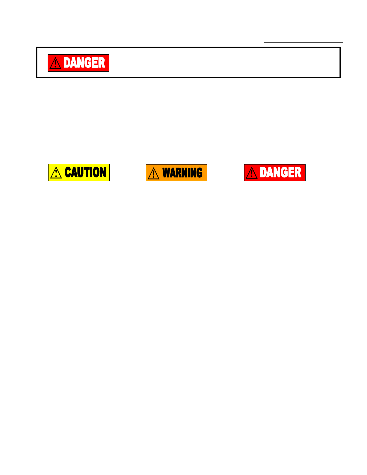
CAUTION indicates a
potentially hazardous
situation which, if not
avoided, could result in
m inor or m odera te injury.
It may also be used to
alert against unsafe
practices.
W A RN IN G ind ica te s a
potentially hazardous
situation which, if not
avoided, could result in
death or serious injury.
DANGER indicates an
imminently hazardous
situation which, if not
avoided, will result in
death or serious injury.
2.2 Inherent Hazards
This product uses electricity and high voltages are present inside the cabinet. This product is equipped with a
lockout/tagout feature on the input circuit breaker to prevent accidentally energizing the product during installa-
tion, maintenance, and/or repair. This product is also equipped with safety interlock circuits, which will de-
energize the product when a cover is removed. In all such cases, hazardous touch voltages will still be present
at the rear of the product’s input circuit breaker where input power feeds are attached. Working on the product
under such circumstances is classified under SEMI S2-0200 as a Type 4 Task. This may be changed to a Type
1 task and complete safety may be assured by disconnecting power to the product (and locking and tagging out)
at the source.
Failure to follow proper safety precautions as well as intentionally defeating the safety interlocks built into the
product’s design will negate the safety features designed into this product and may subject the user to death or
serious injury.
2.3 Alerts and Labels
This product’s enclosure is provided with warning labels in appropriate locations to call your attention to important
user information. The labels and their locations include the following:
Conditioned Power Center
7
Page 8
Section 2 - Safety
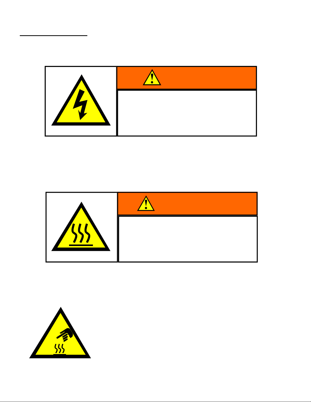
On both removable side panels, near the top of the panel and approximately in the middle are the following warn-
ings. Each calls attention to a specific hazard requiring special attention.
With the front panel circuit breaker of the power conditioner turned off and locked out, potentially hazardous
touch voltages are confined to the input power conductors at the rear of the circuit breaker. Entering the cabinet
under these circumstances is classified as a Type 4 task under SEMI S2-0200 guidelines. This hazard label
alerts personnel to the need to turn off and lock out power to the power conditioner at the facility source. Doing
so will eliminate all potentially hazardous voltages inside the enclosure. Entering the enclosure under these circumstances if a Type 1 task under SEMI S2-0200.
PLEASE NOTE: After extended operation, internal parts of the power conditioner may become very hot.
This hazard label calls attention to the need for protective gear when entering the equipment enclosure.
Inside the power conditioner enclosure another warning similar to the one
shown at the left warns once again of the presence of very hot surfaces
and the potential for injury and burns. This warning is accompanied by
the legend “CAUTION - HOT SURFACE” and is attached to the upper steel
frame of the isolation transformer on the primary side.
Hot surface inside.
Contact may cause burn.
Do not touch.
Wear protective gear before
servicing internal parts.
WARNING
LINE VOLTAGE PRESENT
WITH MACHINE POWER OFF.
Risk of electric shock or burn.
Turn off and lock out facility power before
servicing.
WARNING
8
Conditioned Power Center
Page 9
2.4 Safety Interlocks
This product incorporates a safety interlock circuit that functions as a
secondary means of protection for personnel. Protective side panels and
hazard warning labels provide primary protection. However, in the event one
or more side panels are removed from the product prior to being de-
energized, the safety interlock system will de-energize the power conditioner.
The circuit consists of two safety interlock switches (one per each side access
panel) located in the center of the top side frame of the power conditioner.
Section 2 - Safety
The switches operate as a normally open circuit connected to the shunt trip
coil of the input circuit breaker. See Figure A. Activating either of these safety
interlock switches causes a 24 VDC signal to energize the shunt trip coil of the breaker. The 24 VDC signal is
derived from a low voltage, fused tap on the transformer secondary. The shunt trip circuit also uses stored
energy from a capacitive circuit to ensure that the shunt trip mechanism will function even in the event of a power
outage. The safety interlock switches are shown on the general circuit diagram found in subsection 10.1 of
Section 10 of this manual.
If the power conditioner shunt trips as a result of removing the side panels, hazardous voltages will remain at the input voltage connection to the rear of the main cir-
cuit breaker. Entering the enclosure under these conditions is classified as a Type
4 task under SEMI S2-0200 guidelines. This can be changed to a Type 1 task by disconnecting power at
the source before entering the enclosure.
Figure A
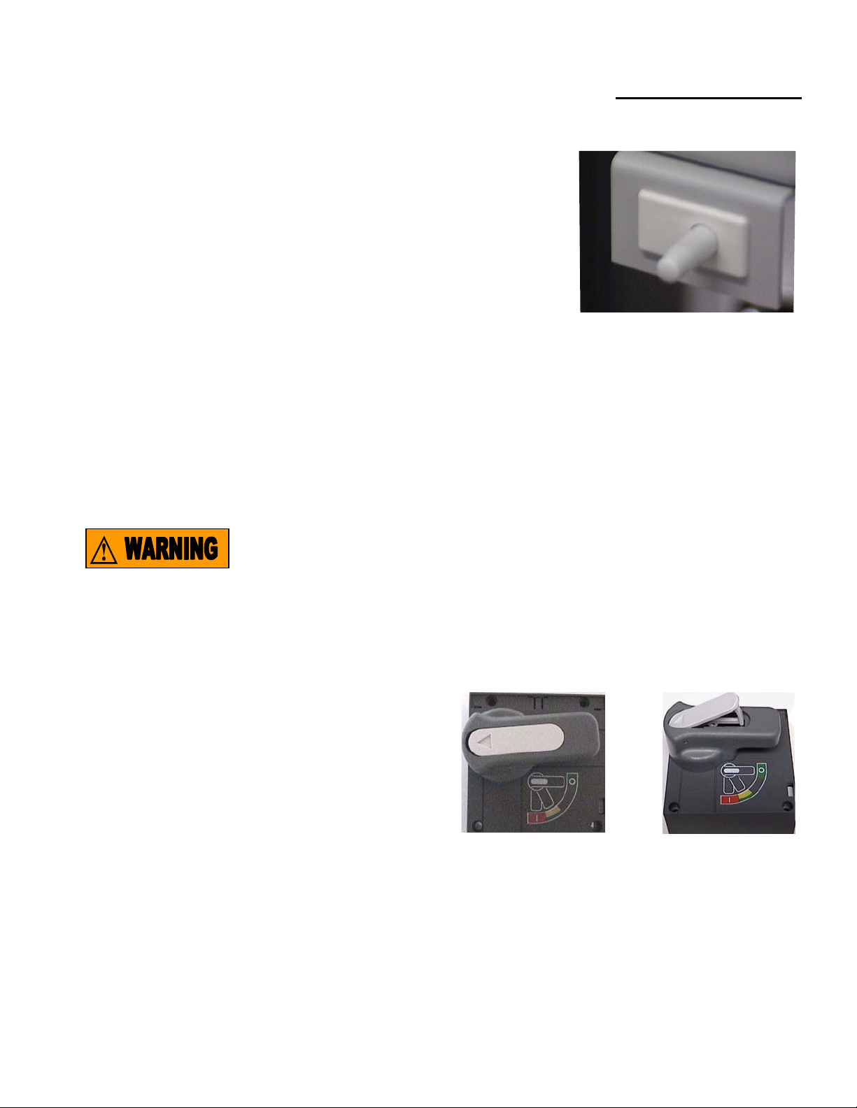
2.5 Lockout/Tagout
The rotary handle of the main breaker is equipped with a
hinged center insert clearly identified with an arrow. The
rotary handle of the main breaker must be in the horizontal
position to proceed. See Figure B. Depress the insert on
the arrow on the left hand side causing the insert to extend
on the right revealing a slot to accommodate a locking
device as shown in Figure C. The lockout/tagout feature is
designed to prevent personnel from accidentally energizing
the power conditioner while maintenance, service or repair
is being performed. With the lockout/tagout engaged, hazardous voltages are still present at the rear of the input
circuit breaker where input power feeds connect to the power conditioner. Entering the enclosure under these
circumstances is classified as a Type 4 Task under SEMI S2-0200. Entering the enclosure may be classified as
a Type 1 Task if power is disconnected from the power conditioner at the source.
Conditioned Power Center
Figure B Figure C
9
Page 10

Section 2 - Safety
2.6 Conformance with Applicable Laws and Regulations
This equipment must be installed and used in accordance with all applicable local, county, state, provincial, and
federal regulations. In the United States, these regulations include, but may not be limited to, those of the NFPA,
NEC, and other regulating bodies. Outside of the United States, other specific laws and regulations may apply.
Compliance with applicable regulations is the responsibility of the installer, user, or owner of the power
conditioner.
2.7 Product Liability
Product liability refers to the liability of any or all parties along the chain of manufacture of any product for
damage caused by the product. Product defects may include inherent design defects, manufacturing defects,
and defects in marketing. The manufacturer of this product has taken every possible precaution to ensure that
design defects do not exist and that manufacturing defects will not occur. Marketing defects generally result from
a lack of proper instructions or failures to warn of latent dangers associated with the product. The manufacturer
has taken great care in preparing this manual to ensure that the documentation is proper, correct, and complete.
However, the manufacturer cannot control how the product documentation is used or how well it is read and
understood. It remains the sole responsibility of the installer, user, and owner of this product to thoroughly review
and understand the documentation that accompanies the product. Those installing, using, servicing, and
maintaining the product should observe all warning notices in both the documentation and on the product and
contact the manufacturer if any part of the installation, use, or service procedures of this product are unclear.
Statutory product liability provisions can be, geographically speaking, very diverse. In the United States, the
Department of Commerce has created a Model Uniform Products Liability Act (MUPLA) for voluntary use by the
states. However, there remains no federal product liability law. For further information consult the products
liability statutes that may apply for the state or country where you reside. Also consult the manufacturer’s
warranty statement in Section 9.3 of this manual concerning implied and expressed warranties of merchantability
and fitness for purpose.
2.8 Emergency Contact Information
In an occurrence requiring emergency assistance from the manufacturer, please call (800) 321-6699. Normal
business hours are 8 am to 5 pm, Central Time. In EMEA, emergency calls should be directed to +44 (0) 1793
553980. Normal business hours for our European operations are 8:00 to 17:00 GMT. Outside of normal
business hours, the manufacturer’s phone systems provide an emergency after hours phone number.
10
Conditioned Power Center
Page 11

Section 3 - Product Overview
Welcome to the world of conditioned power. Electrical power users from around the world benefit from the use of
clean, quality power. That's why we developed the Conditioned Power Center (CPC). The CPC Series is a low-
impedance power conditioner that provides high peak-load capability. You'll find that we've engineered these
products to provide features not readily available as standard equipment on other three-phase power line
conditioning products. The CPC series of products provide the functionality and flexibility that your business
needs in a power quality solution-both now and in the future.
3.1 Product Purpose
The CPC is designed to eliminate high-frequency noise and high-voltage impulses (also known as spikes or
surges) from the AC power that runs your electronic equipment. The power conditioner installs between the
power source and the critical load. And because it is a three-phase device, the CPC provides protection for all
transformer phases that power a large system. Sophisticated electronic systems contribute to the profitability of
your business, and clean power is an essential element in their reliable operation. Each electronic system
responds to power-quality problems differently, but properly protected systems benefit in a variety of ways. These
benefits include fewer hardware failures, fewer "no problem found" service calls, less system downtime, higher
manufacturing yield, better image quality and longer equipment life.
The CPC power conditioning series incorporates these three important power quality elements:
1. A low-impedance isolation transformer - The transformer is the "heart" of the power conditioning system. It
provides unequaled protection against common mode (neutral to ground) disturbances and voltages. In addition,
it provides all the criteria necessary to meet National Electrical Code 250-5d requirements for a "separately
derived power source." The isolation transformer can be specified to accommodate the variety of electrical supply
voltages and frequencies that are encountered throughout the world.
2. A low pass filter - The filter is responsible for removing normal mode (phase to neutral and phase to phase)
noise components from the electrical power. These power disturbances are the ones that are caused by your
system's "electrical neighbors" (i.e. elevators, copy machines, motors, HVAC equipment and even other
computer systems).
3. A surge diverter - The surge diverter is part of the input (primary) circuit of the isolation transformer. This
ensures that any voltage impulses generated within the facility (our outside of it due to occurrences like lightning
and utility activities) do not interfere with the connected system. Although the surge diverter is designed to
handle substantial energies, catastrophic events may occur, which damage one or more of the circuit’s protective
elements. If such damage occurs, one or more of the TVSS Fault LEDs on the power conditioner’s front panel
will illuminate. Consult Section 8.1.3 for instructions on how to proceed if a TVSS Fault LED illuminates.
Conditioned Power Center
11
Page 12

Section 3 - Product Overview
3.2 Standard Features
These include a “power on “ LED, TVSS Fault LEDs (one per phase), a lockout/tagout provision for the front
panel input circuit breaker, safety interlocks, casters, and leveling feet. In addition, the CPC offers a range of
options as described below.
3.3 Optional Features
Input line cord - This option is available on models 45 kVA and smaller.
Output receptacles - This option is available on all models. A range of different receptacle styles (each with
over-current protection) may be added to the CPC power conditioner.
Distribution panels - This option is available only on models 85 kVA and larger. It provides a standard 42 circuit
Square D panelboard from which the conditioner’s power may be distributed to individual branch circuits each
with their own dedicated circuit breaker.
External EMO connector - This optional connector (if so equipped) is part of the power conditioner’s EMO
(emergency machine off) circuit. It provides a point for connecting the power conditioner’s EMO circuit to an
external control or the master EMO circuit of a computer room or similar facility. See Section 7.3
Seismic anchorage brackets - This options permits stabilization of the power conditioner in seismically active
(earthquake prone) areas. Seismic design data is included in the specification sheet found in Section 10.
A 5th harmonic filter - The GPI Series 2000 may be ordered with an optional passive 5th harmonic filter. When
so equipped, the CPC will significantly reduce the fifth odd order harmonic current regardless of origin (line or
load). Passive harmonic filters tuned to other order harmonics are available special order. Consult the
manufacturer for more information. If the CPC you are installing is equipped with an optional harmonic filter,
consult Section 7.1 of this manual for complete information regarding it’s location and operation.
Zig-Zag transformer - This option is only available on models 85 kVA and larger. Special transformers with
zigzag secondary windings for the elimination of harmonic currents are available as a special order from the
manufacturer.
Basic metering/Power management package - All CPC models may be equipped with basic metering
functions using Power Measurements Limited 6200 ION monitor. A full power management package is available
on models 85 kVA and larger. This package uses a Power Measurements ION 7500 monitor and provides
multiple functions including low voltage/phase loss/phase reversal detection and protection.
12
Conditioned Power Center
Page 13

Section 3 - Product Overview
complete monitoring of three phase voltages, currents, phase angles, power factor, demand, energy usage,
event logs and more. If the CPC is equipped with the power management option, documentation prepared by
Power Measurements Limited will accompany this manual. The table below illustrates a matrix of standard
equipment and options for each model of GPI Series 2000.
3.4
Feature
Matrix
S= Standard
O= Option
NA = Not Available
ABC10.0-XDXY S S O S S S S O O NA O O NA NA O NA
Power On LED
TVSS Fault LEDs
Safety Interlocks
EMO Pushbutton
Lockout/Tagout
Casters
Leveling Feet
Input Line Cord
Output Receptacles
Distribution Panel
Ext. EMO Contacts
Harmonic Filter
Seismic Anchorage
Basic Power Meter
Zig Zag Transformer
Power Management
ABC15.0-XDXY S S
ABC20.0-XDXY S S O S S S S O O NA O O NA NA O NA
ABC25.0-XDXY S S O S S S S O O NA O O NA NA O NA
ABC30.0-XDXY S S O S S S S O O NA O O NA NA O NA
ABC35.0-XDXY S S O S S S S O O NA O O NA NA O NA
ABC45.0-XDXY S S O S S S S O O NA O O NA NA O NA
ABC55.0-XDXY S S O S S S S NA O NA O O NA NA O NA
ABC65.0-XDXY S S O S S S S NA O NA O O NA NA O NA
ABC75.0-XDXY S S O S S S S NA O NA O O NA NA O NA
ABC85.0-XDXY S S O S S S S NA O O O O O O O O
ABC100.0-XDXY S S O S S S S NA O O O O O O O O
ABC125.0-XDXY S S O S S S S NA O O O O O O O O
ABC150.0-XDXY S S O S S S S NA O O O O O O O O
O
S S S S O O NA O O NA NA O NA
ABC175.0-XDXY S S O S S S S NA O O O O O O O O
ABC200.0-XDXY S S O S S S S NA O O O O O O O O
ABC230.0-XDXY S S O S S S S NA O O O O O O O O
ABC250.0-XDXY S S O S S S S NA O O O O O O O O
ABC300.0-XDXY S S O S S S S NA O O O O O O
Conditioned Power Center
O O
13
Page 14

Section 4 - Preparation
IMPORTANT ! Each unit is fully inspected and tested prior to leaving the factory. CPC series products
are packed carefully in approved shipping crates. However, since we cannot control handling during
shipping, damage in transit is possible. Please retain all packing materials until the power conditioner is
installed and operating satisfactorily. If damage to the shipping container is evident, you may file a claim
with the shipper. Concealed damage can also be claimed with the shipper within fifteen (15) days.
Immediately contact the shipping company to arrange for any visual inspection or report. Contact the
manufacturer if you require assistance. Do not install or apply power to units if there is external damage
or if internal components or connections are loose or "rattle." Always check all electrical connections
during installation to verify a tight connection.
4.1 Unpackaging
The CPC series is packaged in a sturdy shipping container. For models 20 kVA and smaller, the container
consists of a shipping pallet/skid with an outer cardboard housing. For models 25 kVA and larger, the shipping
container consists of a bottom pallet/skid, a packing block, four wooden sides, and a top.
For 20 kVA and smaller conditioners, perform the following five steps to remove the power conditioner from the
packaging crate.
Step 1 - Remove the outer cardboard carton from the shipping pallet.
Step 2 - The power conditioner is attached to the shipping pallet with metal bands. Using a metal snips or band
cutter, cut the metal bands and remove them from the packing crate.
The metal bands are under tension. When cut, they may spring out of control if not
held securely. The bands may be very sharp. Gloves and eye protection are recommended before cutting and removing the metal bands. Failure to follow this pre-
caution may result in injury to eyes or other body parts. Wear protective gear.
Step 3 - Remove the protective plastic bag and foam cushion wrap and dispose of appropriately.
Step 4 - Consult Figure D on Page 16. Remove the 2 x 4 cleat at the front of the pallet by removing the lag
screws.
Step 5 - Remove the front 4 x 4 shipping skid by removing the lag screws. The shipping pallet may now be
“rocked” forward on the center skid allowing the power conditioner to roll off the pallet onto the floor.
Refer to the diagram in Figure E on page 16 for unpacking power conditioners 25 kVA and larger. You will need
a Phillips screwdriver (preferably power) and a band cutter or metal snips. Follow these seven steps.
Step 1 - Remove the top of the packing crate by removing the screws that secure the top to the four sides of the
crate. Once the screws are removed the top may be lifted off the crate and set to one side.
14
Conditioned Power Center
Page 15

Section 4 - Preparation
Step 2 - A packing block assembly rests on top of the power conditioner to secure it tightly inside the packing
crate. Remove the packing block assembly by removing the screws that are driven through the crate front and
back panels into the ends of the wooden struts. The packing block may now be removed and set to one side.
Step 3 - The front and back panels of the packing crate should be removed next. The front and back panels are
secured to the side panels and to the shipping pallet with screws along the edges and bottom of the panels.
Remove the screws from one panel at a time. Remove the panels and set them to one side.
Step 4 - The side panels are removed next by removing the screws that secure them to the pallet. Remove the
screws from the bottom of the side panels and set the panels to one side.
Step 5 - The power conditioner is attached to the shipping skid with metal bands. Using a metal snips or band
cutter, cut the metal bands and remove them from the packing crate.
Step 6 - The power conditioner is wrapped in foam cushion wrap and then enclosed in a protective plastic bag to
prevent moisture from entering the enclosure. Remove the outer plastic bag and foam cushion wrap from the
power conditioner and dispose of them appropriately.
Depending on the rating, the CPC power conditioner may weigh as much as 3000
pounds (1500 kg.). The next steps involve removing the power conditioner from the
shipping skid. Carelessness may result in injury.
Step 7 - The power conditioner is now free of the shipping container and bottom pallet/skid. A fork truck with
sufficient fork length and height and a minimum rating of two tons may be used to raise the power conditioner a
few inches off the bottom pallet.
IMPORTANT ! Never lift the power conditioner with the forklift from the front. Doing so may damage the
front bezel. Always lift the power conditioner with the forklift on the side or back.
Once raised clear of the bottom pallet, pull the pallet away from the power conditioner and set it off to the side
with the rest of the shipping container panels. The power conditioner is shipped with the threaded leveling feet
extended for stability. Retract the leveling feet by turning them in a sufficient number of turns. This will allow the
power conditioner to rest on its casters when lowered to the floor. The power conditioner may now be lowered to
the floor and the fork lift removed.
Take a few minutes to inspect the unit for any visible damage. If damage is present, contact the carrier for an
inspection before proceeding. If no damage is present, move the power conditioner to its installation location on
its casters. Once placed into its final position, make sure the unit is leveled and stabilized using the leveling feet.
Conditioned Power Center
15
Page 16

Section 4 - Preparation
2
4
Figure D - Shipping Crate Disassembly - 10 to 20 kVA
1. Cardboard outer carton
2. Shipping pallet
3. 2 x 4 front cleat
4. Front skid
After removing the front
cleat and front skid, the
pallet may be rocked forward on the middle skid
and the power conditioner
may be easily rolled off the
pallet and onto the floor.
1
3
2
4
Figure E—Shipping Crate Disassembly - 25 kVA to 300 kVA
1. Crate Top
2. Packing Block
3. Front Side
4. Back Side
5. Right Side
6. Left Side
7. Shipping Pallet/Skid
Shipping crate should be disassembled in the numerical
order shown. Removing panels 1 through 7 will provide
total access to the power conditioner, which is enclosed in
foam wrap and plastic and
banded to shipping skid #7.
6
3
1
5
7
IMPORTANT ! Retain all parts of the shipping container and packaging material until after the CPC series
has been installed and proper operation verified. Once installed and operational integrity is verified, the
packaging material may be discarded.
16
Conditioned Power Center
Page 17

Section 5 - Installation
5.1 Location
For best performance, the CPC series should be installed within fifty (50) wire feet maximum of the protected
load. Refer to the dimensional information shown in the specifications sheet accompanying this document. Allow
six inches of free space on all sides of the CPC series to provide for proper air circulation. The unit is designed to
operate at high efficiency and is convection cooled. If the unit is installed in a facility that has a raised flooring
system, ensure that the flooring system can support the weight of the ETA power conditioner. Consult the
specification sheet found in Section 10 of this manual for dimensions and weights.
The power conditioner is not weatherproof and must be installed in a dry location.
During winter months, the transition from cold temperatures to a warm indoor
climate may result in significant condensation. Make sure that the power
conditioner has been given enough time to acclimate to its environment and that condensation has
evaporated before installing and energizing the conditioner.
5.2 Conduit Landings
The power conditioner is designed to accept conduit landings on the top panel, rear panel and on the unit bottom
(for raised floor applications). It is not possible to land conduits on the side panels due to interference with the
ventilation slots and/or the internal frame components.
5.2.1 Top Feed
Conduit holes may be punched or cut anywhere in the top panel except within 3” of any edge. It is important to
avoid landing conduits within 3” of the panel edges to prevent interference with the frame of the power
conditioner. Consult the specification sheet in Section 10 of this manual for additional guidance.
5.2.2 Rear Feed
Consult the specification sheet in Section 10 of this manual for allowable rear conduit landing locations.
Prior to drilling or cutting any top or rear panel, the panel must be removed.
Drilling or cutting conduit access holes with panels mounted on the conditioner
may result in metal shavings or other debris falling into or on the transformer or
other system components resulting in damage when power is applied to the system. The manufacturer
is not responsible for damage caused by improper or careless installation. Please take proper
precautions by removing panels before drilling, cutting, or punching conduit access holes. Failure to
follow this precaution will void the product warranty.
5.2.3 Bottom Feed
Consult the specification sheet in Section 10 of this manual for allowable bottom conduit landing locations.
Conditioned Power Center
17
Page 18

Section 5 - Installation
5.3 Outer Panel Removal
The side panels, the back panel, the top panel and the front panel have all been designed for easy removal prior
to installation. The side panels must be removed first. Turn the quarter turn fasteners counterclockwise and
remove the side panels.
A bonding strap is attached to the bottom of each side panel with a hand fastener
and lock-washer. The bonding strap electrically grounds the side panel to the
frame during normal operation. This bonding strap must be disconnected for
complete removal of the side panel taking care not to misplace the fastener and lock-washer. It is
extremely important that the bond strap be reconnected to the side panel when the side panel is
replaced. Failure to reconnect the ground strap may result in an electrical shock hazard in the event of
an electrical fault.
The back panel, top panel and front panel are held in place by threaded fasteners, which are accessible once the
side panels have been removed. Removing these fasteners will allow the top, back, and front to be removed.
5.4 Alternate Conduit Landing Locations
In the event, it is not possible to land conduits on the power conditioner top, rear, or bottom panels, consult with
the manufacturer. Although less desirable, alternate conduit landings can be accommodated. The manufacturer
can provide information, detailed drawings, and instructions for landing conduits at alternate locations.
5.5 Main Input Circuit Breaker
Depending on the primary voltage configuration of the power conditioner’s isolation transformer, the conditioner
will be equipped with one of two types of circuit breakers. If the power conditioner uses a single voltage primary
(i.e. 480 volts) the power conditioner will come equipped with a circuit breaker rated at the proper amperage to
accommodate the power conditioner’s power rating at the specified input voltage. If the isolation transformer has
a primary voltage configuration capable of accepting multiple input voltages through the use of changeable taps,
the power conditioner will be equipped with a programmable circuit breaker. Prior to being shipped, a tag is
attached to the main circuit breaker of each power conditioner on the front panel. The tag indicates the
transformer primary configuration, breaker type, and input voltage setting. Based on the type of circuit breaker
shown on the tag, consult either Sec. 5.5.1 or 5.5.2 for more information
5.5.1 Fixed Input Circuit Breakers
Before beginning installation, check the tag on the circuit breaker. The power conditioner has been
manufactured and shipped according to the input voltage specified at the time the order was placed. If the input
voltage information shown on the tag does not match the voltage available at your site and if the tag indicates the
transformer in the power conditioner has a single voltage primary, then the input circuit breaker will have a fixed
value. Under the circumstances, you will not be able to proceed with the installation. Contact the company who
18
Conditioned Power Center
Page 19

Section 5 - Installation
5.5.2 Programmable Circuit Breakers
Before beginning installation, check the tag on the circuit breaker. The power conditioner has been
manufactured and shipped according to the input voltage specified at the time the order was placed. If the input
voltage information shown on the tag does not match the voltage available at your site, check the tag to
determine the transformer primary configuration and circuit breaker type. If equipped with a programmable circuit
breaker and a transformer with a multiple voltage primary, it will be necessary to adjust the transformer’s primary
taps. Transformer primary tap connections are included in the specification sheet found in Section 10 of this
manual.
Breaker operating parameters such as input current, inrush characteristics, and time delay may all be
programmed to make it easier to adapt the power conditioner in the field to a full range of site installation
voltages. In order to reprogram the circuit breaker, it is necessary to gain access to the front of the breaker itself.
This is accomplished by removing the side panels as described previously in Sec. 5.3. Once the side panels
have been removed, proceed as follows:
1. The front bezel is attached to the frame of the power conditioner with screws on each side of the conditioner
frame. Remove the screws on each side of the front bezel, and remove the bezel from the power conditioner. (If
equipped with optional power management package or basic metering package, it will also be necessary to
unplug the wiring harness connecting the power management computer to the power conditioner before
removing the bezel. This is done by disconnecting at the Molex connector).
2. The front control panel is now accessible. It is hinged on the left side. Undo the screw on the right side of the
control panel and swing the control panel out to the left exposing the front of the breaker.
3. A hinged cover protects the breaker DIP switches. Raise the cover to gain access to the DIP switches.
Change DIP switch settings using the instructions included in the specifications sheet found in Section 10 of this
manual. Consult the manufacturer if you have any questions or difficulties.
5.6 Isolation Transformer
NOTE: CPC series power conditioners utilize a low-impedance isolation transformer. When first
energized, transformers of this kind typically exhibit a high "inrush" current that may approach 10-15
times the nominal rating. While inrush currents quickly decay to nominal, it is possible to experience
"nuisance" tripping of the source circuit breaker. If this occurs consult the manufacturer for options.
Conditioned Power Center
19
Page 20

Section 5 - Installation
Transformers are designed to meet a variety of requirements. Some locations (Europe, for example) have
standardized on a single input voltage. In other cases customers may specify multiple input voltages to
accommodate the variety of voltages commonly found in the United States. The CPC series conditioner can
accommodate either style of transformer - single voltage or multiple voltage primary.
The conditioner is a "delta-wye" system. The input or primary side of the transformer accepts power from either a
delta or wye power system at the voltages for which the transformer has been designed. Delta feeds are
desirable because they reduce wiring and installation costs by eliminating the neutral conductor from the input
wiring arrangement. In addition, feeding the CPC series with a higher input voltage reduces input amperage and
further reduces installation costs by allowing the use of less expensive, smaller gauge electrical conductors and
conduits. Consult the tag on the input circuit breaker. If the power conditioner you are installing has a single
voltage primary, the site voltage must match the transformer primary voltage. Power conditioners with multiple
voltage primaries may be changed to accommodate a variety of site voltages.
The secondary configuration of the transformer is a five wire wye requiring three phase conductors, a neutral,
and a safety ground.
5.6.1 Transformer Primary Voltage Adjustment
Figure F
Depending on the design of the isolation transformer, the
power conditioner may accommodate different input voltages.
The voltages are selected by changing primary taps. If
necessary, changes may be made to the input voltage setting
by changing connections on the transformer primary windings
at the locations shown in Figure F to the left. Most voltage
changes can be accomplished in 15 minutes or less. Consult
the specification sheet found in Section 10 of this manual for
detailed information on the specific connections required to
accommodate any of the allowable input voltages. In the event
that the voltage adjustment information in this manual is
missing, input voltage configuration information is also shown
on a data plate attached to the top of the transformer as shown
in Figure G to the left.
20
Figure G
Conditioned Power Center
Page 21

5.6.2 Output Voltage Fine Adjustment
The transformer secondary of the power conditioners is a 5 wire
Wye configuration (three phase conductors, one neutral and one
safety ground). Output voltage can be adjusted plus-or-minus five
Section 5 - Installation
percent ( +
site-specific voltage differences . This is accomplished by moving
the output lugs and connections on the transformer secondary.
Consult the information found in Section 10.4 on page 37 of this
manual for detailed information on the location of the transformer
secondary taps and the settings necessary to make fine
adjustments up or down.
IMPORTANT! Output power feeds connect directly to the lugs provided at the transformer secondary. If
the CPC series power conditioner is equipped with the Power Management Option, it will be necessary (if
changing output voltage taps) to also move current transformers to the appropriate transformer
secondary tap at the same time the output lug and associated wiring is moved.
5%) (as shown in Figure H to the right) to accommodate
Figure H
5.7 Grounding
The presence of a code legal safety ground on both the input and the output
circuits of the power conditioner is required to prevent fire hazards and to ensure
personnel safety. If a safety ground connections cannot be made or are made
incorrectly, do not proceed with the installation until this problem is corrected. Failure to observe this
warning may result in fire or electrical shock hazard in the event of an electrical fault.
The CPC series product family is considered to be information technology equipment for the purposes of the
National Electrical Code as defined in NEC Article 645. Before proceeding, please review any requirements for
proper grounding of the conditioner. This is critical for proper operation as well as personnel safety and fire
prevention. Grounding requirements and guidelines can be confusing. Contact the manufacturer if you are unsure
about proper grounding methods or techniques.
The National Electrical Code (NEC), in Article 250-20d, describes a "separately derived system" as one in which
the output neutral is bonded to safety ground. The key advantage of such an arrangement is the complete
elimination of neutral to ground (common mode) voltages and noise at the point of power delivery to a critical
load. The power conditioner meets all the requirements for a separately derived system as defined by U.S. and
Canadian electrical codes.
Conditioned Power Center
21
Page 22

Section 5 - Installation
Specific locations for connecting the input and output safety ground conductors are discussed in Sections 5.9 and
5.10 that follow. These sections cover the information necessary to connect electrical wiring to both the main and
to the load. Please review both sections carefully before beginning the actual electrical installation. A
sophisticated electronic system will benefit greatly when all parts of the system and all system peripherals are
powered from a single power source. It is recommended that all parts of the system share this common power
source and its common, "clean" ground. Non-isolated code minimum input safety grounds are permitted.
Dedicated input safety grounding conductors are also permitted. They may be either isolated or non-isolated. If
an isolated input safety ground connection is desired, it should be a continuous, insulated, isolated conductor that
is routed directly back to the service entrance panel-board. The ground lug connection of the power conditioner
may also be connected to a separate grounding electrode or to building steel, provided that a separate low-
impedance grounding path (either copper conductor or conduit) is present and connects to the electrical system
ground. Excellent guidelines for grounding practices are also available by consulting the Federal Information
Processing Standards Publication (FIPS Pub. 94) published in 1983.
Connecting input wiring to the main source of power may require working inside
switchgear or distribution panelboards containing live voltages. Contact with live
voltages will result in injury or death. Working inside live switchgear is classified
as a Type 4 Task under SEMI S2-0200 guidelines. Prior to beginning input power connections, be sure to
follow any lockout/tagout procedures pertinent to your service equipment. Failure to observe this
warning may result in live voltages being present on conductors being connected to the input power
connections of the power conditioner.
Strict compliance with the following lockout/tagout procedure for the CPC series is
required to assure personnel safety when making input and output power
connections. Working inside the power conditioner with the lockout/tagout
engaged may be classified by SEMI S2-0200 guidelines as a Type 4 task if electrical power is not deenergized and locked out at the source. If also locked out at the source, the task is reduced to Type 1.
5.8 Lockout/Tagout Procedure
The rotary handle of the main breaker must be in the
horizontal (OFF) position to proceed. The rotary handle is
equipped with a hinged center insert clearly identified with
an arrow. See Figure I at left. Depressing the insert on
the arrow on the left hand side will cause the insert to
extend on the right. This will reveal a slot to accommodate
Figure I Figure J
(tagout) should be affixed to notify personnel that input power to the power conditioner has been locked out.
22
a locking device as shown in Figure J to the right. Place a
locking device in the slot and lock it. A warning label
Conditioned Power Center
Page 23

Section 5 - Installation
5.9 Input Power Connections
The three-phase input connection is made at
the lugs marked L1, L2, and L3 directly on the
main circuit breaker shown in Figure K to the
right. The safety ground connection is made
at the dual lug marked “PE” on the rear of the
panel immediately behind the main circuit
breaker shown in Figure L to the right. Locate
all connection points prior to committing to the
conductor lengths. Input conductor sizes are
determined by electrical code. For the convenience of the installer, the manufacturer has provided these, along
with other installation information, on the specification sheets included in Section 10 of this manual. Consult the
specification sheet for the conductor sizes required for the power conditioner.
5.10 Output Power Connections
The load is connected to the lugs provided on the transformer's secondary
Figure K Figure L
winding shown in Figure M to the right. Safety ground is connected to the
Neutral/Ground bus lug. This device provides a neutral ground bond. The
transformer secondary is also equipped with additional taps that allow the
installer to make fine adjustments to the output voltage of plus-or-minus
five percent ( +
voltage differences. The power conditioner is shipped with the output
conductor connection lugs attached to the nominal output voltage
connection. If it is necessary to utilize the fine adjustment taps, the output conductors and the connection lugs
must be moved to the appropriate tap. For detailed connection diagrams, consult Section 10.4.
IMPORTANT NOTE! If this power conditioner is equipped with the basic metering or the power
management option, be sure to also move the associated current transformers to the appropriate
transformer secondary tap at the same time the output lug and output conductors are moved.
5%) of nominal output to accommodate site-specific input
Figure M
5.11 Models With Optional Line Cord/Output Receptacles
CPC series models 45 kVA and smaller may be equipped with optional input line cords. CPC series models of all
sizes may be equipped with optional output receptacles. If equipped with an input power cord, the installation
instructions discussed in paragraphs 5.9 will not apply. If equipped with output receptacles, the installation
instructions discussed in paragraph 5.10 may not apply. In all cases, it remains critical to observe all grounding
practices discussed in paragraph 5.7. If equipped with both line cord and receptacles, installation is a plug and
play operation. In any case be sure the site voltage matches the power conditioner configuration.
Conditioned Power Center
23
Page 24

Section 6 - Operation
6.1 Restoring For Service
When wiring connections have been completed (or after maintenance or repair operations are finished) it will be
necessary to perform several tasks before the power conditioner can be put into service. Take these steps in the
following order:
1. Verify that all electrical connections are tight.
2. Verify that the enclosure, transformer and all other internal components are free of metal shavings, debris,
and installation/maintenance tools.
3. Replace any front, top, rear, or side panels that have been removed.
4. Disengage the lockout/tagout provision at the source (if engaged).
5. Disengage the lockout/tagout provision on the front panel circuit breaker of the power conditioner.
A bonding strap is attached to the bottom of each side panel with a hand fastener
and lock-washer. The bonding strap electrically grounds the side panel to the
frame during normal operation. This bonding strap must be reconnected to the
side panel when the side panel is replaced. Failure to reconnect the ground strap may result in an
electrical shock hazard in the event of an electrical fault.
6.2 Energizing the Power Conditioner
Once the power conditioner has been installed, it’s time to apply power and verify its proper operation. Perform
the following steps:
1. If equipped with the harmonic mitigation option, turn on the harmonic filter circuit breaker.
2. Rotate the front panel circuit breaker’s rotary handle one quarter turn clockwise to the “On” or red position.
3. Verify that the green “power on” LED is illuminated and the red TVSS Fault LEDs are extinguished (this is the
normal state for the front panel LEDs).
4. If equipped with either the basic metering or the power management option, verify that the Power
Measurements device is powered on and operating. If so equipped also verify steps 6 and 7 below. If not
equipped with either option, proceed to Section 6.3.
5. Using the keypad on the Power Measurements device, verify the that phases A, B, and C are present.
6. Verify that phases A, B, and C each show the correct nominal voltage for the load being powered. Voltages
must match the voltage requirements of the load.
NOTE: The installer may verify the output voltage of the power conditioner using an appropriate
voltmeter at either the output receptacles of the power conditioner (if so equipped) or at the input power
terminals inside the connected load. This final step is recommended prior to energizing the load.
24
Conditioned Power Center
Page 25

Section 6 - Operation
(NOTE: Under "no load" conditions, the transformer in the power conditioner will "step up" the output
voltage a few percent. This design characteristic compensates for losses within the transformer once
actual load is applied. As a result, an output voltage that is slightly higher than the nominal input voltage
is normal under unloaded conditions.)
(NOTE: For further information on Power Measurements Limited meters or monitors, consult the
separate owner’s manual. A separate manual will accompany this document if the power conditioner is
equipped with either option.)
6.3 Energizing the Load
Power is now available to the load. Perform the following steps in the order shown.
1. Energize the load in accordance with any recommended load power-up procedures.
2. Verify the proper operation of the load and the entire system.
3. If equipped with the basic metering or the power management option, you may use the keypad on the Power
Measurements monitor, to observe and/or verify the following:
a) Load currents for Phase A, B, and C are properly indicated
b) All other monitor functions are operating normally. (A manual is included as Section 10 with this
document if the power conditioner is equipped with the power management option.)
If all connections have been properly made and correct operation of the system has been verified, normal
operations may begin. The power conditioner is now quietly providing full-time protection to your critical system.
In the event that the power conditioner is ever dangerously overloaded for any reason, the main circuit breaker
will shut off, removing power from the connected load.
6.4 Orderly Shutdown
To shutdown the power conditioner in an orderly manner, first turn off all connected loads. Then turn off the
power conditioner by rotating the handle of the front panel circuit breaker one quarter turn counter-clockwise to
the “off” position. Verify that the front panel green power LED is extinguished. No residual energy is stored after
then power conditioner is de-energized.
Conditioned Power Center
25
Page 26

Section 7 - Options
7.1 Passive Harmonic Filter
The passive harmonic filter package is located below the transformer
secondary on the left side of the power conditioner. See Figure N to the
left. This circuit is bi-directional. It will mitigate odd order harmonic
currents originating from the load or
harmonic filters have a tendency to "sink" harmonics regardless of the
source, it is necessary to protect this circuit in the event of excessive
odd order harmonic content in the facility electrical system. To
Figure N
circuit breaker will trip. The circuit breaker may be reset while the power conditioner is operating. Unless the
source of excessive harmonic current is located and corrected, the circuit breaker will likely trip again
immediately.
NOTE: The CPC series will operate properly and provide power conditioning even if the harmonic
mitigation breaker is tripped. The breaker may be reset with power applied to the unit. However, it will be
necessary to address the harmonic condition of the facility electrical system if breaker tripping persists.
accomplish this, the power conditioner provides a circuit breaker on the
front panel. Should the facility have excessive odd order harmonics, the
the facility. Because passive
7.2 Basic Metering
If equipped with this option, a Power Measurements Limited Series 6200 ION compact modular power meter will
be installed in the front panel adjacent to the input circuit breaker. The 6200 ION provides energy and demand
measurements, per phase voltage, current, frequency and power factor, peak current demand, THD, and other
real-time, true RMS electrical parameters. Communications capability is also available. Contact the
manufacturer of the power conditioner for more information about optional communications capabilities.
7.3 Power Management
If equipped with this option, the power conditioner will have a Power Measurements Limited Series 7500 ION
power monitor installed in the front bezel. The 7500 ION is shown in Figure X. The 7500 ION monitor provides
measurement of critical operating parameters such as voltage, current, power factor and demand. It also
provides the ability to monitor apparent power, true power, reactive power and to display vector diagrams,
harmonic currents and a wealth of other information in either alphanumeric or bar graph formats. The 7500 ION
monitor stores waveforms and event logs and makes them available to facilities or systems managers when
equipped with one of several optional communications interface cards. Optional communications interfaces
include, 10Base-T or 10Base-FL Ethernet, RS-232, RS485, or modem connections. An optical port on the front
panel is standard. Contact the manufacturer of the power conditioner for more information about optional
communications capabilities.
26
Conditioned Power Center
Page 27

Section 7 - Options
7.4 Phase Loss/Low Voltage Detection and Protection
When equipped with the power management option, the 7500 ION monitor also provides:
1. Protection from the loss of one or more input phases
2. Protection for a low-voltage condition occurring on one or more phases (Protection from a high-voltage
conditions is also optionally available)
Should a phase loss or low voltage occur, the 7500 ION will “shunt” trip the power conditioner breaker within 50
msec. of the occurrence. In this event, turn off the load. Then re-energize the GPI Series 2000 input breaker to
return power to the power conditioner. The 7500 ION monitor may then be used to diagnose the event that
caused the shunt trip. If the power conditioner immediately trips again once it is energized, this indicates that the
low voltage or phase loss condition that originally caused the shunt trip still exists and must be corrected prior to
restoring operation. (Shunt trip delays other than 50 msec. can be programmed via the 7500 ION monitor.
Consult the manufacturer for instructions or assistance.
NOTE: Any phase that drops below 80% of nominal voltage is considered a “phase loss” condition. The
7500 Ion monitor is powered from phase A of the transformer secondary. If the 7500 Ion monitor appears
to have no power, this is an indication that phase A may be lost. Caution should be exercised, however,
as phases B and C may be still be energized.
7.5 External EMO
If equipped with the external EMO option, the power conditioner will be provided
with a set of terminals as a point for connecting the power conditioner’s EMO
circuit to a remote pushbutton or as a means to integrate it into the master EMO
circuit frequently found in computer rooms or semiconductor production facili-
ties. The external EMO contact terminal block is marked ‘TB1” and is located
inside the power conditioner on the rear of the panel immediately behind the
main circuit breaker as shown in Figure O to the right. The external EMO con-
tacts are clearly marked. When connected to an external EMO circuit, the acti-
vation of any EMO pushbutton or control anywhere in the master circuit will acti-
vate the shunt trip circuit of the power conditioner.
Figure O
7.6 Seismic Anchorage
When equipped with seismic anchorage brackets, the power conditioner will meet the requirements of SEMI S2-
0200 Paragraph 19 . The seismic anchors are designed to allow the power conditioner to withstand a horizontal
loading of 63% of the power conditioner’s weight acting on its own center of mass. Seismic anchorage brackets
are designed to prevent the power conditioner from overturning during seismic activity and possibly injuring per-
sonnel. Consult the specification sheet found in Section 10 of this manual for detailed information and drawings
showing physical dimensions, anchorage locations, weight distributions, and center of mass locations. Seismic
anchorage kits may be ordered for any installation and are not restricted solely to SEMI applications .
Conditioned Power Center
27
Page 28

Section 7 - Options
7.7 SEMI S2-0200 Certification
For use in semiconductor fabrication applications, the manufacturer offers a version of the power conditioner that
incorporates special modifications of the basic product family that are required for the power conditioner to meet
the safety requirements of the Semiconductor Equipment and Materials International (SEMI) safety standard S2-
0200. Included in the additional requirements for SEMI S2-0200 certification are provisions for special labeling,
an approved EMO (emergency machine off) circuit, input power conductor restraints (for additional safety in seis-
mically active locations), and product documentation that meets or exceeds the criteria specified in SEMI S2-
0200. Compliant documentation and labeling are provided with every product. Choosing the SEMI S2-0200
option adds the following additional features:
7.7.1 Input Power Conductor Restraints
SEMI S2-0200 guidelines recognize that the power conditioner, when used in semiconductor operations, may
be installed in geographic areas that experience frequent (sometimes violent) seismic activity. The seismic an-
chorage option described in paragraph 7.6 is designed to limit horizontal and vertical movement of the power
conditioner, and since the product may be installed in seismically active locations for non-semiconductor applica-
tions, the anchorage kit is provided as a separate option. For full compliance with SEMI S2-0200, however,
SEMI requires that the input power conductors also be provided with a restraint system to prevent their detach-
ment from the input circuit breaker up to the limits of movement provided by the anchorage kits. When ordered
with the SEMI S2-0200 certification option, the power conditioner will be fitted with a steel bracket installed inside
the power conditioner enclosure running horizontally from side to side and near the top of the enclosure. At-
tached to this steel bracket is a plastic bag containing additional hardware for clamping the input power conduc-
tors to the steel restraint bracket. Once the input power conductors have been attached to the input circuit
breaker, the clamping hardware should be installed.
Take care not to severely over-tighten the clamping hardware to the extent that
the input power conductors are greatly distorted or the conductor insulation is
damaged in any way. Doing so may lead to conductor failure or short circuit,
which is not covered by the product warranty.
7.7.2 SEMI S2-0200 Compliant EMO
The EMO (emergency machine off) circuit provided with the SEMI S2-0200 option is considerably different from
the standard EMO design due to the incorporation of additional components designed to increase personnel
safety. For a complete details on the design of the SEMI-S2-0200 EMO circuit, please consult the schematics
on pages 34 (general system schematic), 35 (standard EMO circuit, and 36 (SEMI S2-0200 EMO) found in this
product manual. The standard EMO circuit operates as a normally open (N.O.) circuit that, when
28
Conditioned Power Center
Page 29

Section 7 - Options
activated by the closure of an interlock switch or EMO button, provides a DC voltage to the over-voltage shunt
trip coil of the input circuit breaker. In the standard EMO design, the DC voltage is derived via a full wave bridge
rectifier powered from a 24 volt AC tap on the main transformer secondary winding.
For SEMI S2-0200 approval, the EMO functions differently from the standard EMO. The SEMI S2-0200 EMO
operates as a normally closed (N.C.) circuit which provides a continuous DC voltage to an under-voltage shunt
trip coil in the input circuit breaker. Activating the EMO pushbutton or a panel interlock opens the safety circuit
and removes DC voltage activating the shunt trip. The DC voltage is derived from a separate 24 volt AC step-
down transformer powered from the output side of the input circuit breaker. When first starting the GPI Series
2000, no power is available at the circuit breaker output since it’s under-voltage shunt trip will ensure that it re-
mains in the tripped position. When first starting the power conditioner, it is necessary to provide power to the
EMO circuit. This is accomplished via a “push to start” pushbutton located on the front panel. The button is iden-
tified by a label with the legend “DEPRESS BUTTON WHILE ENERGIZING MAIN BREAKER” The “push to
start” button energizes the EMO circuit power transformer from the input side of the input circuit breaker, which
provides the initial DC voltage to energize the under-voltage shunt trip of the input circuit breaker. For starting
GPI Series 2000 power conditioners equipped with SEMI S2-0200 option, follow these simple steps:
1. Make sure that the input circuit breaker is rotated fully to it’s farthest left position.
2. Make sure that the EMO pushbutton is in its operating position (turn in direction of arrow to disengage)
3. Press and hold the “push to start” button while rotating the input circuit breaker to the right
4. Verify that the “power on” LED on the front panel is illuminated
5. Release the “push to start” button
The power conditioner will now be operating normally and any connected loads may be energized. Please con-
sult the schematics on pages 34, 35, and 36 of this manual for more information.
If a power conditioner equipped with the SEMI S2-0200 option is de-energized for
any reason (including a shunt trip due to EMO or interlock activation), mains power
will still be present at the input side of the input circuit breaker, and at the terminals
of the “push to start” switch. Working inside the power conditioner under these conditions may be
classified by SEMI S2-0200 guidelines as a Type 4 task. The task may be reduced to Type 1 if mains
power is de-energized and locked out at the facility source. The manufacturer recommends locking and
tagging out the facility source whenever it is necessary to enter the power conditioner enclosure.
Conditioned Power Center
29
Page 30

Section 8 - Troubleshooting/Maintenance
8.1 Conditions Requiring Troubleshooting
Four conditions may occur, which require operators or service personnel to troubleshoot the function of the power
conditioner. Each may be individually evaluated. These four occurrences include:
1. Source circuit breaker (at switchgear or distribution panelboard) trips out
2. Front panel circuit breaker trips out
3. TVSS Fault LED (one or more) illuminate
4. Harmonic filter circuit breaker trips out (if equipped with harmonic filter option)
8.1.1 Source Circuit Breaker Trip
The power conditioner utilizes a low-impedance isolation transformer. When first energized, transformers of this
kind typically exhibit a high "inrush" current that may approach 10-15 times the nominal rating. While inrush
currents quickly decay to nominal, it is possible to occasionally experience "nuisance" tripping of the source
circuit breaker. If this occurs, consult the manufacturer for direct assistance in troubleshooting this condition.
8.1.2 Input Circuit Breaker Trips
In the event the front panel breaker on the power conditioner trips out, one of five conditions is likely at fault. You
may effectively troubleshoot this condition by checking each of the following five areas. They are listed in order
or probability.
8.1.2.1 Electrical Load Has Exceeded Capacity - If the amount of electrical load has exceeded the
capacity of the power conditioner, the front panel circuit breaker is designed to trip. Load may exceed capacity
as a result of a short circuit in the load or too much load having been added to the power conditioner. In either
event, turn off all load power switches and recycle power to the conditioner by turning the circuit breaker handle
to the extreme counter-clockwise position and then rotating back to the clockwise “On” position. If this restores
the power conditioner to normal operation (with no loads powered up) it will be necessary to either remove load
from the conditioner or troubleshoot the load to determine if a short circuit condition exists.
8.1.2.2 Phase Loss or Low Voltage Occurrence - This condition will cause the front panel circuit
breaker to trip only
condition, rotate the circuit breaker handle to the extreme counter-clockwise position and then rotate clockwise to
the “On” position. If the phase loss/low voltage condition was temporary the power conditioner will once again be
operating and the 7500 ION monitor can be used to retrieve the phase loss or low voltage data from the log files.
If after resetting the circuit breaker it immediately trips out once again, this is an indication that the phase loss or
if the power conditioner is equipped with the power management option. To troubleshoot this
low voltage condition is still present. If a phase loss or low voltage is found not to exist consult the following
sections for information on further troubleshooting on additional failure conditions.
30
Conditioned Power Center
Page 31

Section 8 - Troubleshooting/Maintenance
Prior to performing maintenance of any kind, lockout and tagout the electrical
power at both the facility source and the input circuit breaker. Under these condi-
tions, entering the equipment enclosure will be classified as a Type 1 task under
SEMI S2-0200 guidelines. Power must be locked out and tagged out at both locations prior to entering
the enclosure for maintenance purposes.
8.1.2.3 EMO Has Been Activated - The front panel EMO pushbutton latches in a closed position once it
has been depressed. Ensure that the EMO button has not been depressed by turning the button in the direction
of the arrows and allowing it to spring back to its normal operating position. If the power conditioner is equipped
with the external EMO option, further ensure that remote EMO buttons or connected external EMO circuits have
not been activated. Once all EMO buttons and circuits have been verified, rotate the circuit breaker handle to the
extreme counter-clockwise position and then rotate clockwise to the “On” position. If the circuit breaker once
again trips immediately, contact the manufacturer for further instructions.
8.1.2.4 Safety Interlocks Activated - Check both side panels of the power conditioner for proper instal-
lation and secure fit. Both panels must be firmly in place and securely fastened with the quarter turn fasteners
provided. A loose or improperly attached panel will allow the safety interlocks to activate and shunt trip the front
panel circuit breaker. Once the panels have been checked, rotate the circuit breaker handle to the extreme
counter-clockwise position and then rotate clockwise to the “On” position.
If the circuit breaker once again trips immediately, contact the manufac-
turer for further instructions.
8.1.3 TVSS Fault LEDs Illuminate
If one or more TVSS Fault LEDs illuminate, it is an indication that the
TVSS components may be damaged. These components are protected
by fuses. The TVSS module and it’s associated fuses are located inside
the power conditioner enclosure, on the right side below the isolation transformer as illustrated in Figure P to the
right. The TVSS module itself is attached to the rear of the mounting panel. Three resistors are associated with
the fuses. The resistors function as “pull up” resistors to light the front panel LEDs should one or more of the
fuses open. The TVSS module, fuses, and resistors are accessed by removing one or both side panels as de-
scribed in Section 5.3.
The fuses may be checked for continuity using an ordinary multi-meter. Open fuses may be replaced on site us-
ing an Amptrap ATQ20, Time Delay, 10 kA IR, 500 VAC, 20A fuse or equivalent. Once the fuses have been
replaced, replace the side panels as described in Section 6.1 taking care to reattach the grounding straps. Once
Figure P
completed, rotate the circuit breaker to the clockwise “On” position. If one or more of the TVSS Fault LEDs re-
illuminate, the fuses have opened once again. This indicates that the TVSS element is damaged and requires
replacement. Contact the manufacturer to order a replacement part.
Conditioned Power Center
31
Page 32

Section 8 - Troubleshooting/Maintenance
8.1.4 Harmonic Filter Circuit Breaker Trips Out
If equipped with a harmonic filter option, the power conditioner will incorporate a
passive harmonic filter. One characteristic of such filters is that they tend to
“sink” harmonics regardless of whether the source is the load or the facility. In
some circumstances, it is possible that the load and the facility together may
require more reactive current than the filter is rated to provide. For that reason,
models equipped with the harmonic filter option include a circuit breaker to
pretect the filter from delivering reactive current current in excess of its capabili-
Figure Q
the left. The circuit breaker will trip if its reactive current capabilities are exceeded. The circuit breaker may be
reset at any time without interrupting the operation of the power conditioner. However, unless the source of ex-
cessive harmonics is located and eliminated, the circuit breaker is likely to once again trip as soon as it has been
reset. If tripping of the harmonic circuit breaker is frequent and persistent, this is an indication of high harmonic
content within the facility electrical system which could be investigated and corrected.
8.2 Routine Maintenance
ties. The circuit breaker is located on the front panel as illustrated in Figure Q to
Little routine maintenance is required for the CPC series to function reliably for many years. Depending on the
application for which the power conditioner is being used, however, occasional routine cleaning may be recom-
mended. Some applications and installation environments generate significant dust residue. This may be espe-
cially true in printing facilities. Because the CPC series is convection cooled, it is important to prevent dust
buildup from blocking the ventilation slots. Dust buildup should also be removed from inside the power condi-
tioner enclosure. Dust may be easily removed with any ordinary shop vacuum. Remove dust as often as re-
quired to keep ventilation slots clear and excessive dust from accumulating inside the enclosure.
To perform maintenance inside the enclosure, it will be necessary to de-energize the power conditioner as de-
scribed in Section 6.5 and remove the side panels as described in Section 5.3. Make sure to observe Section 6.1
carefully when completed before returning the power conditioner to service.
32
Conditioned Power Center
Page 33

Section 9 - Service and Support
9.1 Technical and Service Assistance
In North and South America, the manufacturer offers toll-free technical and customer service assistance by
calling 800-321-6699. Business hours are Monday through Friday, 8:00 a.m. to 5:00 p.m. Central Time. In
EMEA, contact the manufacturer’s international headquarters in the United Kingdom at +44 (0) 1793 553980. UK
business hours are 8:00 to 17:00 GMT. In the event of an emergency outside of normal business hours, the
manufacturer’s phone systems provide an emergency after hours phone number. Technical and service inquiries
may also be communicated to us via our website at www.etasys.com by clicking on the link for Technical
Support. You may also register your ownership of the product on the .
9.2 Customer Service
Should it ever be necessary to obtain service on your power conditioner, please obtain the following information
from the data plate attached to the rear of the unit. To process service requests, we will require:
• Model number
• Part number
• Serial number
With this information in hand, contact the manufacturer at the numbers given above to arrange for service. In
most cases, the power conditioner will require service on site. Units may only be returned to the manufacturer
after obtaining a Return Material Authorization (RMA) number. This number must be clearly marked on the
shipping container and packing slip accompanying any returned product. Unauthorized return shipments will be
refused. Units to be returned must be shipped prepaid to the manufacturer in an appropriate shipping container.
Additional charges will be billed for repair costs due to shipping damage resulting from inadequate packing.
9.3 Product Warranty
The manufacturer warrants its power conditioner (known hereafter as the “product”) to be free from defects in
material and workmanship for a period of five years from the date of shipment. The product will be repaired or (at
manufacturer’s option) replaced at no charge during this warranty period. The manufacturer makes no
warranties, expressed or implied, of merchantability, fitness for a particular purpose, performance, condition,
capacity or otherwise. The manufacturer is not liable for incidental or consequential damages, monetary loss,
loss of sales, or loss of business resulting from failure or malfunction of the product. Warranty is void on any
product that is misused, misapplied, abused, altered or repaired by any unauthorized personnel or where
evidence of tampering exists. The foregoing constitutes the sole and exclusive remedy of the purchaser and is in
lieu of all other warranties. No greater degree of liability is imposed on the manufacturer.
Conditioned Power Center
33
Page 34

Section 10 - Specifications
10.1 CPC Series Schematic
A4—Page 35
B3—Page 36
34
Conditioned Power Center
Page 35

C4—Page 34
Section 10 - Specifications
10.2 GPI Series 2000 Standard EMO
Conditioned Power Center
35
Page 36

Section 10 - Specifications
10.3 GPI Series 2000 Semi S2 EMO
C4—Page 34
36
Conditioned Power Center
Page 37

10.4 Output Voltage Fine Adjustment
IMPORTANT: ALL WORK TO BE DONE
BY A LICENSED ELECTRICIAN
Section 10 - Specifications
-5%
Nominal +5%
Nominal +5%
-5%
-5%
Nominal +5%
TRANSFORMER SECONDARY
The output voltage of the transformer may be adjusted +5% from nominal using the taps shown above. First
disconnect the power and all load equipment. After removing the side panels, move the wire from the
“nominal” transformer tap to the desired adjustment tap to adjust output voltage up or down. Replace side
panels. Then energize the transformer and check for proper desired voltage at output before reconnecting
and energizing the load.
IMPORTANT NOTE: BE SURE TO ADJUST THE TAPS ON ALL THREE PHASES.
Conditioned Power Center
37
Page 38

Document Revision History
Part # Title Rev. Letter Rel. Date Next Rev. Leve l
SM5505 Conditioned Rev. A 03/01/2006 Rev. B
Power Center
38
Conditioned Power Center
Page 39

ETA Systems
1450 Lakeside Drive
Waukegan, IL 60085
(800) 321-6699
Phone: (330) 677-4424 - Fax: (330) 677-4471
http://www.etasys.com
Conditioned Power Center
SM5505- Rev. A - 03/01/2006, © 2006 ETA Systems.
39
 Loading...