

ETA Systems 350VA, 500VA, 800VA, 1100VA, 1440VA User Manual

ETA Systems
1450 Lakeside Drive
Waukegan, IL 60085
Phone: (330) 425-3388
Fax: (330) 425-9700
Toll Free: (800) 321-6699
On the web @ http://www.etasys.com
© 2005 ETA Systems SM 5501-RevA
Uninterruptible Power Manager
350VA, 500VA, 800VA, 1100VA, 1440VA
Managed Power
User’s Guide
Guía Del Utilizador
Le Guide De l'Utilisateur
Anleitung Des Benutzers
Guida Dell' Utente

ETA SYSTEMS® - UNINTERRUPTIBLE POWER MANAGER
CONTENTS – CONTENIDO – CONTENU – INHALT – SODDISFARE
ENGLISH
1.0 – First ..............................................................1
2.0 – Safety Issues................................................2
3.0 – FCC Issues ..................................................4
4.0 – DOC Issues.................................................. 4
5.0 – Overview ......................................................5
6.0 – Operation .....................................................6
7.0 – Unpacking, Inspection, Testing ..................12
8.0 – Battery Replacement..................................16
9.0 – Warranty.....................................................17
10.0 – Specifications ...........................................91
11.0 – Illustrations ...............................................96
ESPAÑOLES
1.0 – Primero.......................................................18
2.0 – Seguridad................................................... 19
3.0 – FCC Información ........................................21
4.0 – DOC Información .......................................22
5.0 – Visión General............................................22
6.0 – Operación...................................................24
7.0 – Disempaque, Examen................................ 30
8.0 – Reemplazo De La Batería.......................... 35
9.0 – Garantía .....................................................36
10.0 – Especificaciones ......................................91
11.0 – Ilustraciones .............................................96
FRANCAIS
1.0 – D ‘Abord .....................................................37
2.0 – Sûrete.........................................................38
3.0 – Issues De FCC........................................... 40
4.0 – Issues De DOC ..........................................40
5.0 – Vue D’Ensemble ........................................41
6.0 – Execution ...................................................42
7.0 – Eclament, Inspection, Dépannage .............48
8.0 – Remplacement De Batterie ........................52
9.0 – Garantie .....................................................53
10.0 – Caractéristiques .......................................91
11.0 – Illustrations ...............................................96
DEUTSCH
1.0 – Allgemeines ...............................................54
2.0 – Sicherheits Hinweise ................................. 55
3.0 – FCC Richtlinien.......................................... 57
4.0 – DOC Richtlinien .........................................58
5.0 – Übersicht.................................................... 58
6.0 – Bedienung.................................................. 60
7.0 – Entpacken, Kontrolle, Prüfung ................... 66
8.0 – Batterie Wiedereinbau ...............................71
9.0 – Garantie ..................................................... 72
10.0 – Spezifikationen ........................................ 91
11.0 – Abbildungen............................................. 96
ITALIANO
1.0 – In Primo Luogo .......................................... 73
2.0 – Sicurezza ................................................... 74
3.0 – Soggetti Del FCC....................................... 76
4.0 – Sogetti Del DOC ........................................77
5.0 – Sommario .................................................. 77
6.0 – Funzionamento .......................................... 79
7.0 – Disimnballagio, Ispezione.......................... 85
8.0 – Rimontaggio Della Batteria ........................ 89
9.0 – Garanzia ....................................................90
10.0 – Specifiche ................................................91
11.0 – Illustrazioni............................................... 96

ETA SYSTEMS - UNINTERRUPTIBLE POWER MANAGER
1
1.0 - FIRST
Thank You
Choosing a power quality solution for your audio/video application can be a daunting task. That’s especially
true when it comes to selecting a product that delivers uninterruptible power, since there are so many on the
market to choose from. Everyone at ETA SYSTEMS thanks you for selecting an ETA SYSTEMS power
quality solution for your application. We understand that your decision was a careful one and that your
purchase of an ETA SYSTEMS product is an expression of confidence in our company. We promise to
always work our hardest to make certain that your confidence in our products and our company is well
deserved. Thank You!
The product you have purchased is the most advanced solution available today. It does so much more than
provide backup power for your application. In fact, it’s so advanced that it actually serves as a
comprehensive management interface between your system and its supply of electrical power. That’s why
we refer to it as an Uninterruptible Power Manager or UPM.
We’ve prepared this document to help familiarize you with the functions and controls of the UPM family. If,
after reviewing this manual, you have any questions at all, please feel free to contact us by phone or email.
Registering your UPM Purchase
Please take a few moments to register your product purchase. Registration is easy and quick via the
enclosed product registration card.
Technical Support
In North America, ETA SYSTEMS provides technical product support during our regular business hours of
8:00 a.m. to 5:00 p.m. Central Time. Between the hours of 5:00 p.m. and 8:00 a.m., our phone mail system
will allow you to leave a message for our support department. The phone mail system also provides an
emergency number to call in the event you should require immediate assistance. You may also
communicate with our customer service/support department via fax or email. In North America, call (800)
321-6699. Our fax number is (330) 425-9700. You may also email at etasys@etasys.com
.
Warranty
ETA SYSTEMS warrants its uninterruptible power managers or UPM (known hereafter as the "product") to
be free from defects in materials or workmanship for a period of five years from the date of shipment.
Batteries are warranted for two years. The product will be repaired or (at ETA SYSTEMS's option) replaced
at no charge during this warranty period. Product must be returned prepaid to the factory. See Page 18 for
the full text of ETA SYSTEMS’ product warranty on the UPM series.
ETA SYSTEMS - UNINTERRUPTIBLE POWER MANAGER
2
2.0 – SAFETY ISSUES
IMPORTANT – SAVE THESE INSTRUCTIONS
THIS MANUAL CONTAINS IMPORTANT SAFETY INSTRUCTIONS. KEEP THIS MANUAL
HANDY FOR REFERENCE.
CAUTION: A BATTERY CAN PRESENT A RISK OF ELECTRICAL SHOCK.
SHORT-CIRCUIT CURRENTS CAN BE EXTREMELY HIGH AND CAN CREATE
SEVERE BURNS AS WELL AS THE RISK OF FIRE OR EXPLOSION FROM
VENTED GASES. ALWAYS OBSERVE PROPER PRECAUTIONS.
WHEN REPLACING BATTERIES, USE THE SAME QUANTITY, RATING AND
TYPE OF BATTERIES USED BY ETA SYSTEMS. THE BATTERIES USED IN
THIS UPM ARE SEALED LEAD-ACID AND ARE MAINTENANCE FREE.
CONSULT THE CHART BELOW FOR QUANTITY AND RATING. PROPER
DISPOSAL OF BATTERIES IS REQUIRED. REFER TO YOUR LOCAL CODES
FOR DISPOSAL OF BATTERIES.
UPM Rating QUANTITY AND BATTERY
RATING
350 VA 2 X 4.5AH @ 12 VOLT
500 VA 2 X 4.5AH @ 12 VOLT
800 VA 2 X 7AH @ 12 VOLT
1100 VA 2 X 11AH @ 12 VOLT
1440 VA 4 X 7AH @ 12 VOLT
CAUTION !!
¾ THIS UPM CONTAINS VOLTAGES WHICH ARE POTENTIALLY HAZARDOUS. ALL REPAIRS
SHOULD BE PERFORMED BY QUALIFIED SERVICE PERSONNEL.
¾ THE UPM HAS ITS OWN INTERNAL ENERGY SOURCE (BATTERY). THE OUTPUT
RECEPTACLES OF THE UPM MAY BE LIVE EVEN WHEN THE UPM IS NOT CONNECTED TO AN
AC SUPPLY.
Safe and continuous operation of the UPM depends partially on the care taken by users.
Please observe the following precautions.
ETA SYSTEMS - UNINTERRUPTIBLE POWER MANAGER
3
PLEASE NOTE:
¾ Do not disassemble the UPM
¾ Do not attempt to power the UPM from any receptacle except a properly
grounded receptacle that matches the input plug provided with the UPM.
¾ Do not place the UPM near water or in environments of excessive humidity.
¾ Do not allow liquid or any foreign object to get inside the UPM.
¾ Do not block air vents on the side of the UPM.
¾ Do not plug appliances such as hair dryers, fans, heaters, etc. into the UPM.
¾ Do not place the UPM under direct sunshine or close to heat emitting sources
(excessively warm temperatures will shorten battery life).
¾ This UPM is intended for installation in a temperature controlled, indoor area
free of conductive contaminants.
¾ The AC power supply for the UPM should be conveniently near the UPM and easily accessible –
avoid extension cords or temporary power strips to power the UPM.
¾ The total leakage current of the UPM and consumer connected equipment should not exceed 3.5
mA.
¾ The battery should be disconnected from the UPM by unplugging at its quick connectors when
maintenance or service work inside the UPM is necessary.
¾ Do not dispose of batteries in a fire – batteries may explode.
¾ Do not open or mutilate batteries. Doing so may release electrolyte or other toxic substances,
which may be harmful to the skin, eyes, or the environment.
A battery can present a risk of electric shock and high short circuit current. The following
precautions should be observed when working with batteries:
¾ Remove watches, rings, or any other metal jewelry or objects which may make contact with the
battery.
¾ Use tools with insulated handles.
¾ A certified detachable power supply cord is to be used with this equipment. For the 350, 500,
and 800 VA models, a type not lighter than SJT 18AWG should be used. For the 1100 and 1440

ETA SYSTEMS - UNINTERRUPTIBLE POWER MANAGER
4
VA models, a type not lighter than SJT 16AWG should be used. (Also applies to Ground Guard,
Hospital Grade, and Medical versions of this UPM product.)
3.0 – FCC ISSUES
Attention:
This equipment has been tested and found to comply with the limits for a Class A and B digital devices,
pursuant to Part 15 of the FCC rules. These limits are designed to provide reasonable protection against
harmful interference in both residential and commercial environments.
This equipment generates, uses, and can radiate radio frequency energy and if not installed and used in
accordance with the instructions, may cause harmful interference to radio communications. However, there
is no guarantee that interference will not occur in a particular installation. If this equipment does cause
harmful interference to radio and/or television reception, which can be determined by turning the UPM
equipment on and off, the user is encouraged to try to correct the interference by one or more of the
following measures:
¾ Reorient or relocate the receiving antenna.
¾ Increase the separation between the UPM and the receiver.
¾ Connect the UPM into an outlet on a circuit that is different from that to which the receiver is
connected.
¾ Consult the dealer or an experienced radio/TV technician for assistance.
4.0 – DOC ISSUES
Attention:
This equipment does not exceed Class A or Class B limits for radio noise emissions from digital apparatus
set out in the Radio Interference Regulation of the Canadian Department of Communications. Operation in
a residential or commercial area may cause unacceptable interference to radio and TV reception
requiring the owner or operator to take whatever steps are necessary to correct the interference.

ETA SYSTEMS - UNINTERRUPTIBLE POWER MANAGER
5
5.0 – OVERVIEW
General
The ETA SYSTEMS series of Uninterruptible Power Managers are the most advanced, line-interactive, true
sinewave UPM products available for your application. Each model is designed to provide total protection
for your system from a complete range of power quality problems. ETA UPM solutions will protect your
installation from normal mode voltage impulses, electrical noise, sags and surges, protracted brownouts,
and complete blackouts. And because each UPM contains an isolation transformer, it completely eliminates
common mode (neutral to ground) voltages that are a constant threat to the reliable operation of
microprocessor based systems. When AC power is present, the UPM constantly filters and conditions the
power supply. When AC power fails, the UPM uses its internal, maintenance-free battery to supply reserve
power to your computer system. Regardless of whether or not commercial power is present, the UPM is
constantly on the job, ensuring a fully conditioned, safely managed interface between your computer system
and its electrical power supply. Figure 1 illustrates the basic operation of the UPM.
Sinewave Output
The output voltage of all ETA UPM models is a true, low distortion sinewave – the kind that the utility
company provides to the wall outlet and the kind that your equipment is designed to work with. This
provides guaranteed compatibility even with the most sensitive electronic loads.
Voltage Manager
™
The voltage of the AC power source can often fluctuate from its nominal rating. These deviations in line
voltage are tolerated quite well by most switch mode power supplies (the type used in many modern
electronic systems). However, some UPS products may misinterpret these transient changes in line voltage
as a power outage and erroneous battery operation may occur. This type of activity results in unnecessary
strain on the battery and may eventually shorten its life. ETA SYSTEMS’s UPM products feature Voltage
Manager – a circuit that constantly monitors the AC power source. If minor changes in AC voltage occur,
Voltage Manager adjusts the input voltage to the UPM circuitry so that erroneous inverter operations are
avoided. Ensuring that the UPM switches to its batteries only in the event of a true power outage results in
longer battery life and a lower cost for both maintenance and ownership.
Start Manager
™
Start Manager is special circuitry that allows you to start the UPM from either the main AC supply or from its
own internal battery. On occasion, AC power may not be available – such as when installing a system in a
location where the electrical wiring has not been completed. Start Manager allows you to start the UPM and
its connected system to perform final tests on both the UPM and the computer systems it’s powering.

ETA SYSTEMS - UNINTERRUPTIBLE POWER MANAGER
6
Communications Manager™
Many uninterruptible power systems provide only a basic software interface with the computer system they
protect. Communications Manager combines the signaling capabilities of the rear panel communication port
with the management capabilities of ETA SYSTEMS’s communication software suite. Using your
computer’s monitor, Communications Manager conveniently displays input and output voltage, output
current, power line frequency, battery voltage, load percentage, and temperature. Communications
Manager even initiates user defined automatic system shutdowns during extended power outages.
Communications Manager allows a system operator to locally or remotely control the shutdown and startup
of equipment connected to the UPM and provides this control either directly or through the operation of a
customized schedule that can be developed to meet specific operating requirements.
Configuration Manager
™
Configuration Manager allows the user to control certain parameters of the UPM such as operating voltage.
With Configuration Manager, for example, operating voltage of North American units can be set for 120 volts
in the United States or 100 volts for Japanese installations. Some of Configuration Manager’s features are
accessed through Communications Manager – such as those that allow adjustment to the voltage transfer
points of the UPM inverter. With Configuration Manager you can even program output receptacles to turn
off themselves and their connected loads at pre-determined times following a power outage.
User Replaceable Battery
Eventually every UPM requires a new battery. ETA SYSTEMS expects the battery in your to last a minimum
of two years – perhaps longer if power outages are short and infrequent. ETA makes battery replacement
by the user easy and fast. And it’s not necessary to turn off the UPM or the connected system. The battery
may be “hot-swapped” while the system is running.
6.0 – OPERATION
On/Off Button
The On/Off button is a dual function control:
When the UPM is off and AC power is present to the UPM input, pressing the On/Off button for more
than 3 seconds will turn the UPM on. If Start Manager’s rear panel switch is enabled, pressing the
On/Off switch for 3 seconds or more will “cold-start” the UPM on its internal battery.
When the UPM is on, pressing the On/Off button for more than 3 seconds will turn off the UPM and
output power.

ETA SYSTEMS - UNINTERRUPTIBLE POWER MANAGER
7
Test/Silence Button
The Test/Silence button is a dual function control:
Pressing the Test/Silence button when AC power is present and the UPM is operating causes the UPM
to enter a self test mode in which it tests both battery and inverter for a few seconds before returning to
the AC supply. We recommend you close all open files before initiating self-test.
When AC power fails, the UPM warns you with an audible alarm. The Test/Silence button is used to
silence the alarm. When battery power begins to run low, the audible alarm will automatically return
and beep at a faster rate.
Load Monitor
The Load Monitor is a 5-segment LED display that shows the current load percentage. The first four LEDs
each indicate approximately 20% load. When illuminated, the final LED indicates that your connected
equipment is consuming 110% of the UPM rated capacity.
Battery Charge Monitor
The Battery Charge Monitor is a 5-segment LED display that shows the charge capacity of the internal
battery from zero to 100%. Each LED indicates approximately 20% of full charge.
Status Monitor
The status monitor is a row of six individual LEDs that each indicate the status of a part of your UPM
system. The first three LED’s work with ’s Voltage Manager. All six LED’s are explained in the following
table.
LED 1 Voltage Manager Boost Mode: When this LED is illuminated, Voltage Manager has detected that
a low voltage condition exists, and it is compensating by increasing voltage to the UPM input to
the correct level.
LED 2 Voltage Manager Normal Mode: Voltage Manager has determined that input line voltage is
normal and within parameters. No adjustment is necessary.
LED 3 Voltage Manager Buck Mode: When this LED is illuminated, Voltage Manager has detected that
an overvoltage condition exists, and it is compensating by reducing voltage to the UPM input to
the correct level.
LED 4 Battery Mode: When this LED is illuminated, either commercial AC power has been lost or the
UPM has been put into self-test using the Test/Silence button. In Battery Mode, the UPM is
operating on its internal batteries. This LED will remain illuminated until the self-test is completed

ETA SYSTEMS - UNINTERRUPTIBLE POWER MANAGER
8
or until commercial AC power returns.
LED 5 Battery Weak: When this LED is illuminated, the battery requires either recharging or
replacement. If the LED remains illuminated after a 12-hour charge period, the internal battery
should be replaced.
LED 6 Overload: When this LED is illuminated, the UPM is overloaded. Remove load from the UPM by
determining, which of the connected pieces of equipment is the least critical, and disconnect it
from the UPM. Operating the UPM in an overloaded condition, may cause the UPM to protect
itself by shutting down and removing power unexpectedly to all connected components.
Configuration Manager Receptacle Indicators
The four clustered LEDs in the center of the front panel indicate the output receptacle status as controlled by
Configuration Manager. Configuration Manager addresses receptacle control differently for some of the
models (See following explanation).
350 VA models: Configuration Manager treats receptacles 1and 2 as a group (Bank 1) and receptacles
3 and 4 as a group (Bank 2). For these models, LED 1 and 2 (Bank 1) will either be on together or off
together. LEDs 3 and 4 (Bank 2) will also be on or off together. It is not possible to control receptacles
1 and 2 or receptacles 3 and 4 separately. It is only possible to separately control Bank 1 and Bank 2.
500 and 800 VA models
: The top two receptacles are Bank 1 and the bottom four receptacles are Bank
2. On these models, LED 1 and 2 (Bank 1) will either be on together or off together. LEDs 3 and 4
(Bank 2) will also be on or off together. It is not possible to control receptacles 1 and 2 or receptacles 3,
4, 5 and 6 separately. It is only possible to separately control Bank 1 and Bank 2.
1100 and 1440 VA models
: Receptacles 1 and 2 are Bank 1 and LEDs 1 and 2 will either be on
together or off together. Receptacles 3 and 4 are Bank 2 (LED 3) and receptacles 5 and 6 are Bank 3
(LED 4). It is possible to control Bank 1, Bank 2, and Bank 3 independently from each other.
Site Wiring Fault Indicator – (North American Versions Only)
A red Site Wiring Fault LED is located on the rear panel of the UPM. This LED is designed to illuminate if
the UPM is connected to an improperly wired AC receptacle. This indicator is designed to indicate a missing
safety ground wire or a reversal in phase and neutral wiring. This indicator should be visually checked
during installation and, if illuminated, you should contact a qualified electrician immediately.
Note: Do not operate the UPM if the Site Wiring Fault LED is illuminated. When lit, the LED is indicating a
wiring condition, which may represent a hazard of fire or electrocution. In addition, improper wiring may
create reliability problems for both the UPM and the connected system. Never use a 3 blade to 2-blade
adapter (often called a “cheater”) with the UPM. These devices remove the safety ground connection to the
UPM and will cause the Site Wiring Fault LED to illuminate.

ETA SYSTEMS - UNINTERRUPTIBLE POWER MANAGER
9
Communication Manager Port
Communication Manager provides a connection port on the rear panel of the UPM. Connecting to this port
and installing Communication Manager’s software package (optional), will allow you control over important
UPM functions and access to operating information from the UPM. Using Communications Manager’s
software, you can view such parameters as AC input and output voltage, powerline frequency, and battery
voltage. The following table illustrates the available parameters.
Input Voltage Indicates the actual input voltage to the UPM
when AC power is present
Output Voltage Indicates the actual output voltage of the UPM
AC Frequency Indicates the actual output frequency of the UPM
Battery Voltage Indicates the actual DC voltage of the internal
battery buss
Change Battery Indicates the battery is incapable of holding a
charge and requires replacement
Percent Load Indicates the percentage of VA capacity being
used by connected load
Temperature Indicates the actual internal temperature of the
UPM
Communications Manager also can support simple software programs that rely on basic “contact closure”
signaling from the UPM. An example would be the built in UPS Service provided in Windows® NT. The
functions of basic software control usually include the following:
Broadcast warnings of power failures/timed shutdowns
Automatic closure of files prior to battery exhaustion
Power down of the UPM and connected equipment
To support these functions without the Communications Manager software suite, you will need to either buy
or build your own special cable. The following table describes the pin assignment of the DB9 connector on
the rear of the UPM. Contact your computer supplier to determine the connection
configuration and connector style necessary to attach the cable to the computer.
Pin # Description
1 UPM simulates a relay opening between Pins 1 and 4 when
input power fails
2 UPM simulates a relay closing between Pins 2 and 4 when
input power fails
3 UPM sends a RS232 high (12V) 1 second after input power
fails (normally low)
4 Common Ground
5 UPM simulates a relay closing when battery has less than 2

ETA SYSTEMS - UNINTERRUPTIBLE POWER MANAGER
10
minutes runtime left*
6 User sends a RS232 high (5-15V) for 3 seconds. This signal
turns off the UPM until normal input voltage returns. This
signal operates only if the UPM is in battery mode. Pin 6
also functions as the RS232 receive data.
7 Common Ground
8 Reserved
9 RS232 transmit data
* Load Dependent
Notes:
1. Pins 1, 2, and 5 are open collector outputs, which must be pulled up to a common referenced supply.
Switch rating: +40V, 0.15A non-inductive.
2. Pins 4 and 7 should only be connected to ground.
Important Note: You may, of course, connect your computer to the UPM without using
Communications Manager. When power is lost, the UPM will beep and you will have to
manually shut down the computer and UPM.
Configuration Manager
Configuration Manager provides control over important operation parameters of the UPM. Configuration
Manager controls these parameters through the settings on the DIP (dual inline pin) switch pack on the rear
panel and also through certain selections accessed by Communications Manager software.
Operating Voltage: The DIP switches can be used to configure the UPM operating voltage. For North
American models, the UPM can be configured to operate at 100, 110, 115, or 120 volts. International
models can be configured for 220, 230, or 240 volts. The following table illustrates the required switch
settings for each selection.
Voltage Required SW#1 SW #2 SW #3 SW #4
120V/240V Off Off Off Unused
115V/230V On Off Off Unused
110V/220V Off On Off Unused
100V Off Off On Unused
ETA SYSTEMS - UNINTERRUPTIBLE POWER MANAGER
11
If Communications Manager software is installed on the host PC, Configuration Manager can use it to adjust
both Low Voltage Transfer Point and High Voltage Transfer Point. The following table provides the
allowable set points for adjusting transfer voltage (key in all three numbers shown).
Low Voltage Transfer Points (key in all three numbers)
Model Set Pt.
1
Set Pt. 2 Set Pt. 3 Set Pt.
4
North American 089 091 093 096
International 176 181 186 192
High Voltage Transfer Points (key in all three numbers)
Model Set Pt.
1
Set Pt. 2 Set Pt. 3 Set Pt.
4
North American 141 145 148 151
International 282 290 296 302
Low Battery Warning Time: Low battery warning time can be configured for either two or five minutes
before UPM shutdown depending on the requirements of the application. It should be noted that these times
are at full load with a healthy battery. Partial loads and/or aged batteries will affect the accuracy of this timer
setting.
Receptacle On/Off Control: Set the turn-off times of the receptacle groups and individual receptacles on
the rear panel.
Start Manager
When AC power is not available, such as in a new installation where wiring may be incomplete, you can still
start the UPM to test its operation and the operation of your system using Start Manager. With the UPM off,
follow these simple steps:
1. Disconnect the input AC power cable from the rear panel of the UPM.
2. Set the rear panel Start Manager switch to “Enable”.
3. Press and hold the On/Off switch on the front panel until the UPM beeps.
ETA SYSTEMS - UNINTERRUPTIBLE POWER MANAGER
12
4. The UPM is now running on battery. When you have finished, press the On/Off switch again and return
the Start Manager switch to the “Disabled” position. Plug the input AC power cable into the rear panel
of the UPM.
7.0 – UNPACKING, INSPECTION, TESTING AND TROUBLESHOOTING
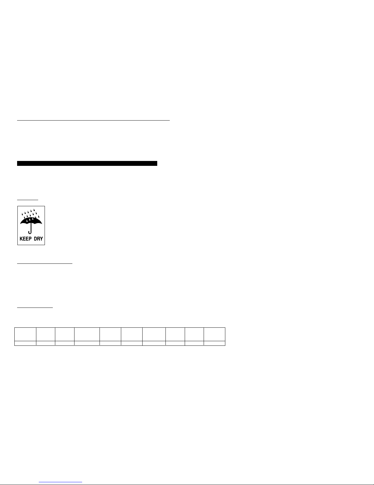
Please Note: Before installation, please read and understand the following instructions. Carefully examine
the packing carton for damage. Notify the carrier immediately if damage is observed. Be sure to save the
carton should you ever need to ship the UPM for repair or maintenance.
Placement
This UPM is intended for indoor use only. Although your UPM is very rugged, its internal
components are not sealed from the environment. The UPM must be installed in a
protected environment away from heat producing appliances such as furnaces, radiators,
and heaters. Protect the UPM from exposure to dripping or standing water and high
humidity or condensing air conditions. The location should provide adequate airflow
around the UPM. Provide a minimum 1” clearance on all sides for proper ventilation.
Applying Power to the UPM
For North American versions, connect the power cord to a verified grounded 3 wire receptacle. For
international versions, unplug the cord from your computer and plug into the inlet of the UPM. Then use the
cord supplied with the UPM to connect the UPM to your computer.
For North American versions, verify that the Site Wiring Fault LED is off. Once properly connected and
initially checked, turn on the UPM by pressing and holding the front panel On/Off switch for 3 seconds.
Operational Tests
Observe the front panel of the UPM. The following table shows how the front panel LED should appear
upon start-up.
Indicator Load
Monitor
LEDs
Battery
Monitor
LED’s
Receptacle
Monitor
LEDs
Voltage
Manager
Boost
Voltage
Manager
Normal
Voltage
Manager
Buck
Battery
Mode
LED
Battery
Weak
LED
Overload
LED
Status Off On All On Off On Off Off Off Off

ETA SYSTEMS - UNINTERRUPTIBLE POWER MANAGER
13
Note: Depending on the charge state of the battery, it is possible that some of the Battery Monitor
LEDs may be off.
With the connected equipment powered off, perform an initial test of the UPM backup function by pressing
the Test/Silence button on the front panel. During this test, the Battery Mode LED on the front panel should
briefly illuminate. It is also possible to test the backup function by unplugging the UPM input power cord. If
you choose to test the UPM in this manner, you will note that the UPM will beep every four seconds while
the power cord is unplugged. The Battery Mode LED will also illuminate constantly.
Once you have performed an initial test of the UPM backup function, turn on the connected computer
equipment. Verify that the Overload LED is off. If the Overload LED is illuminated, remove the least critical
devices from the UPM one by one until the overload light is extinguished. With the connected loads
powered up, perform the backup test once again by pressing the Test/Silence button or unplugging the
UPM. When this final test is completed, the UPM will be ready to use.
Please Note:
If you leave your UPM on continuously, it is a good idea to perform a test at least once a month.
If you are utilizing Communications Manager software, you can configure the system to
automatically self-test periodically.
The UPM is shipped with a charged battery, but some discharge naturally occurs during storage
and shipment. You may use the UPM immediately, but you should realize that backup time may
be less than the stated rating until the UPM battery has had at least six hours to charge.
ETA SYSTEMS recommends that you do not plug laser printers into the
UPM. Laser printers are known to draw large amounts of current when the
fuser/heater assembly is energized. Laser printers can easily overload the
UPM or create a low voltage condition that can interfere with the operation
of the Voltage Manager circuit.
Storage
The UPM may be stored for extended periods in an environment that does not subject the UPM to extremes
of temperature or humidity. When storing for extended periods, the battery should be charged every 3
months. If the storage location is characterized by above normal temperature, the battery should be
recharged every two months. The UPM does not need to be turned on for charging to occur – it only needs
to be plugged in.
Note: This product is not designed for continuous use on batteries.

ETA SYSTEMS - UNINTERRUPTIBLE POWER MANAGER
14
Troubleshooting
The troubleshooting information provided in this section should help you discover the cause of most
commonly encountered difficulties. Before following the troubleshooting steps provided, be certain that you
have verified the following three items:
The UPM should be plugged into a properly working outlet.
The line voltage to the UPM is within specified boundaries.
The circuit breaker on the rear panel of the UPM has been reset.
Problem Possible Cause Action you should take
UPM does not power up
and has no audible alarm
1. On/Off button is not pressed
long enough
2. No incoming line voltage or
voltage too high or too low
3. UPM input power cord is not
plugged in
4. Rear panel circuit breaker is
tripped
1. Press and hold the On/Off
switch for 3 seconds min.
2. Check wall socket and test
for proper line voltage.
3. Plug in input power cord
4. Reduce load and reset
circuit breaker.
UPM Overload LED is
illuminated and continuous
audible alarm sounds
UPM is overloaded Reduce load by removing the least
critical load items from the UPM
output.
Low/Replace Battery LED
is illuminated
Battery voltage is too low or battery
is dead.
Recharge battery for at least six
hours and reset the UPM. If LED is
still illuminated, replace the battery.
Site Wiring Fault LED is
illuminated
Site wiring problem Contact a qualified electrician to
verify wiring at this site.
Backup time is less than
expected
Battery is not fully charged or
battery is dead.
Recharge battery for at least six
hours and retest backup time.
UPM is normal, but the
computer will not turn on.
Computer input power cord is loose
or not connected.
Connect computer input power cord.
Communication Manager
not working
1. Wrong interface cable
2. Computer’s serial port has
not been properly
configured.
3. Computer’s I/O card is bad
1. Purchase correct cable
2. Check to see that the port
is enabled in the CMOS
settings. Also check for
IRQ conflicts. Make sure
settings match those found
in Communications
Manager.
3. Replace I/O card
ETA SYSTEMS - UNINTERRUPTIBLE POWER MANAGER
15
Important Information
The batteries inside this UPM are a special type called “sealed lead-acid”. These batteries use a non-liquid
electrolyte, which makes it possible to use them in any physical orientation. The batteries are designed to
last from 2 to 5 years. Their actual life span will depend on several factors including how often power
outages occur, how long power outages last, and the temperature of the environment in which the UPM
operates. Frequent, long duration power outages will shorten battery life more than infrequent, short
duration outages. Consistent high temperatures in the area where the UPM is used will also shorten battery
life.
The UPM is equipped with a Low/Replace Battery LED on the front panel. If the LED illuminates, you should
make sure that the battery has at least six hours to charge without a power interruption. Inadequate (much
shorter than usual) backup time, premature low battery alarm sounds, and persistent Low/Replace Battery
LED illumination are all good signs that the battery inside your UPM requires replacement. The batteries
inside your UPM are designed to be easily replaced by a user who possesses basic mechanical/electrical
knowledge and simple tools. Please familiarize yourself with the following precautions before proceeding
with battery replacement.
WARNING !!
Servicing of batteries should always be performed or supervised by
someone who has read and understood the following precautions and who
understands the hazards associated with storage batteries. This procedure
should not be performed by someone who is unauthorized or who is
incapable of following these precautions.
OBSERVE THE FOLLOWING CAUTIONS
" Only the battery assembly in this unit is user serviceable. The battery compartment is
accessed by removing the front panel as described in the following instructions. No
other user serviceable parts are contained in this UPM. Do not remove any cover
other than the front battery access panels.
" A battery (even a depleted one) can deliver very high currents when short-circuited.
There is a danger of electrical shock. Remove all watches, rings, bracelets or other
metal objects. Use only tools with insulated handles.

ETA SYSTEMS - UNINTERRUPTIBLE POWER MANAGER
16
" Do not dispose of batteries in a fire. There is a danger of explosion. Do not dispose of
batteries in an environmentally unfriendly manner. Batteries may be returned to ETA
SYSTEMS for proper disposal.
" Do not open or mutilate the batteries. This may release electrolyte that is toxic to the
environment and harmful to the skin and eyes.
" Replacement batteries may be ordered from ETA SYSTEMS by phone at (800) 321-
6699. If purchasing batteries from another source, be sure to use the type and
quantity of batteries described in the table in Section 10.
8.0 – USER REPLACEABLE BATTERY
Please note: Changing the batteries in this UPM is designed to be a safe and simple procedure. Batteries
may be replaced while the UPM is on and providing power to the connected load. You should remember,
however, that if a power outage occurs after the old batteries are disconnected and before the new batteries
are installed, power will be lost to your connected system and components.
Please note: If you have read and understood the cautions preceding this section, you may proceed with
the following steps. Consult Figure 6 to assist you in the following battery replacement procedure.
Battery Replacement
1. Remove the two small screws from the bottom of the front panel that secure the front panel to the frame
of the UPM.
2. Carefully slide the front panel off the UPM taking care not to damage or tear the ribbon cable that
connects the front panel “dashboard” display to the UPM.
3. Remove the screw(s) that secures the battery assembly retaining bracket, remove it from the unit, and
set it to one side.
4. Slide the battery pack from the UPM by pulling on the tab provided.
5. Disconnect the battery from the UPM by pulling apart the wire leads at the connector(s) provided.
6. Connect the new battery pack to the UPM by reconnecting the connector(s) making sure to observe
proper polarity (i.e. black to black and red to red).

ETA SYSTEMS - UNINTERRUPTIBLE POWER MANAGER
17
7. Push the new battery pack into place.
8. Replace the battery retaining bracket removed in step 3 and replace the screw(s) that secures it in
place.
9. Slide the front panel (removed in step 2) back on the front of the UPM taking care not to pinch or
damage the ribbon cable.
10. Replace the front cover screws and tighten.
9.0 – UPM WARRANTY
ETA SYSTEMS warrants its uninterruptible power managers or UPM (known hereafter as the "product") to
be free from defects in materials or workmanship for a period of five years from the date of shipment. ETA
SYSTEMS warrants the batteries used in the product to be free from defects in materials or workmanship for
a period of two years from the date of shipment. The product will be repaired or (at ETA SYSTEMS's option)
replaced at no charge during this warranty period. Product must be returned prepaid to the factory.
ETA SYSTEMS makes no warranties, expressed or implied, of merchantability, fitness for a particular
purpose, performance, condition, capacity or otherwise. ETA SYSTEMS is not liable for incidental or
consequential damages, monetary loss, loss of sales, or loss of business resulting from the failure or
malfunction of the product. Warranty is void on any product that is misused, misapplied, abused, altered or
repaired by any unauthorized personnel or where evidence of tampering exists. The foregoing constitutes
the sole and exclusive remedy of the purchaser and is in lieu of all other warranties. No greater degree of
liability is imposed on ETA SYSTEMS.

ETA SYSTEMS - UNINTERRUPTIBLE POWER MANAGER
18
1.0 – PRIMERO
Gracias
La escogencia de una buena solución en materia de energía para su aplicación en su computadora puede
ser una tarea intimidante. Ésto es especialmente cierto cuando se trata de seleccionar un producto de
suministro de energía ininterrumpible, puesto que hay tantos para escoger en el mercado. Todos nosotros
en ETA SYSTEMS le agradecemos a usted la escogencia de una buena solución en materia de energía —
ETA SYSTEMS— para su aplicación. Nosotros comprendemos que su decisión fue cuidadosa y que su
compra de un producto ETA SYSTEMS es una expresión de confianza en nuestra compañía. Le
prometemos esforzarnos siempre al máximo para sostener la veracidad de que su confianza en nuestros
productos y en nuestra compañía es bien merecida. ¡Gracias!
El producto de que usted ha comprado es hoy por hoy la solución más avanzada disponible. Hace mucho
más que darle capacidad de energía suplementaria a su aplicación. De hecho, es tan avanzado que en
realidad sirve como una interfaz de administración comprensiva entre su sistema de computadora y su
suministro de energía eléctrica. Es por ello que nos referimos al como un Administrador Ininterrumpible de
Energía (Uninterruptible Power Manager o UPM)
.
Hemos preparado este documento para ayudarlo a familiarizarse con las funciones y los controles de la
familia UPM. Si después de revisar este manual usted aún tiene cualquier pregunta, por favor siéntase en
libertad de comunicarse con nosotros por teléfono o email.
El Registro de su Compra UPM
Tome por favor algunos momentos para colocar su compra del producto. El registro es fácil y rápido
vía la tarjeta incluida del registro del producto.
Apoyo Técnico
En Estados Unidos, ETA SYSTEMS brinda apoyo técnico a sus productos en las horas hábiles, de 8:00
a.m. a 5:00 p.m. Tiempo del Centro. Entre las 5:00 p.m. y las 8:00 a.m., nuestro sistema telefónico le
permitirá a usted dejar un mensaje para nuestro departamento de apoyo. Asimismo, el sistema de correo
de voz también suministra un número de emergencia para llamar en caso de que usted requiera ayuda
inmediata. Usted también puede comunicarse con nuestro servicio al cliente/ departamento de apoyo por
fax o email. Llame al (800) 321-6699. Nuestro número de fax es el (330) 425-9700. Usted puede también
email en etasys@etasys.com.
ETA SYSTEMS - UNINTERRUPTIBLE POWER MANAGER
19
Garantía
ETA SYSTEMS garantiza que sus administradores de energía ininterrumpible o UPM (en lo sucesivo
denominados como el “producto”) están libres de defectos en sus materiales o en su manufactura durante
un periodo de cinco años a partir de la fecha de su despacho. Las baterías están garantizadas por dos
años. El producto será reparado o (a opción de ETA SYSTEMS) reemplazado durante este periodo de
garantía, sin cargo alguno. El producto debe ser devuelto a la fábrica con porte pagado. Vea en la Página
38 el texto completo de la garantía de producto ETA SYSTEMS en la serie UPM.
2.0 – SEGURIDAD
¡¡IMPORTANTE !! – CONSERVE ESTAS INSTRUCCIONES
ESTE MANUAL CONTIENE IMPORTANTE INSTRUCCIONES DE
SEGURIDAD. CONSERVE A SU ALCANCE ESTE MANUAL PARA SU
CONSULTA.
PRECAUCIÓN: UNA BATERÍA PUEDE PRESENTAR UN RIESGO DE
CHOQUE ELÉCTRICO. LAS CORRIENTES DE CORTOCIRCUITO PUEDEN
SER EXTREMADAMENTE ALTAS Y PUEDEN PRODUCIR QUEMADURAS
SEVERAS ASÍ COMO EL RIESGO DE FUEGO O EXPLOSIÓN DE ESCAPES
DE GASES. OBSERVE SIEMPRE LAS PRECAUCIONES APROPIADAS.
CUANDO CAMBIE LAS BATERÍAS, USE LA MISMA CANTIDAD, LA MISMA
CLASIFICACIÓN Y EL MISMO TIPO DE BATERÍAS EMPLEADAS POR ETA
SYSTEMS. LAS BATERÍAS USADAS EN ESTE UPM ESTÁN SELLADAS A
PRUEBA DE ÁCIDOS DE PLOMO Y NO REQUIEREN MANTENIMIENTO.
PARA INFORMACIÓN ACERCA DE CANTIDAD Y CLASIFICACIÓN,
CONSULTE LA TABLA QUE SE OFRECE A CONTINUACIÓN.
SE REQUIERE UNA ADECUADA
DISPOSICIÓN FINAL DE LAS BATERÍAS.
PARA LA DISPOSICIÓN FINAL DE LAS BATERÍAS, CONSULTE SUS
CÓDIGOS LOCALES.
UPM Rating QUANTITY AND BATTERY
RATING
350 VA 2 X 4.5AH @ 12 VOLT
500 VA 2 X 4.5AH @ 12 VOLT
800 VA 2 X 7AH @ 12 VOLT
1100 VA 2 X 11AH @ 12 VOLT
1440 VA 4 X 7AH @ 12 VOLT
ETA SYSTEMS - UNINTERRUPTIBLE POWER MANAGER
20
¡¡PRECAUCIÓN!!
¾ ESTE UPM CONTIENE VOLTAJES QUE SON POTENCIALMENTE PELIGROSOS. TODA
REPARACIÓN DEBE SER EFECTUADA POR PERSONAL CALIFICADO DE SERVICIO.
¾ ESTE UPM POSEE SU PROPIA FUENTE INTERNA DE ENERGÍA (BATERÍA). LOS TOMAS DE
SALIDA DEL UPM PUEDEN ESTAR VIVOS AUN SI EL UPM NO ESTÁ CONECTADO A UN
SUMINISTRO DE CA.
La operación segura y continua del UPM depende en parte del cuidado que le den sus usuarios. Por
favor, observe las siguientes precauciones.
POR FAVOR, TENGA EN CUENTA:
¾ No desarme el UPM
¾ No intente ponerle energía al UPM desde ningún toma excepto uno que
tenga la adecuada conexión a tierra y que se ajuste al enchufe
suministrado con el UPM.
¾ No coloque el UPM cerca de agua ni en ambientes con excesiva humedad.
¾ No permita que entren líquidos o ningún objeto extraño al interior del UPM.
¾ No bloquee las salidas laterales de aire del UPM.
¾ No enchufe en el UPM aparatos como secadores de pelo, ventiladores,
calentadores, etc.
¾ No coloque el UPM directamente bajo la luz del sol o cerca de fuentes
emisoras de calor (las temperaturas excesivamente altas pueden reducir la
vida útil de las baterías).
¾ Este UPM está hecho para su instalación en una temperatura controlada, en áreas interiores
libres de contaminantes conductores.
¾ La fuente de energía de CA para el UPM debe estar convenientemente cerca del UPM y debe ser
de fácil acceso. Evite los cables de extensión o las cuerdas de energía temporal para
suministrarle energía al UPM.

ETA SYSTEMS - UNINTERRUPTIBLE POWER MANAGER
21
¾ La pérdida total de energía del UPM y del equipo consumidor conectado no debe exceder los 3.5
mA.
¾ Cuando sea necesario efectuar trabajos de mantenimiento o de servicio en el interior del UPM,
la batería debe ser desconectada del UPM desenchufando sus conectores rápidos.
¾ No descarte las baterías tirándolas al fuego, porque pueden explotar.
¾ No destape ni mutile las baterías. Al hacerlo puede dejar escapar electrolitos u otras sustancias
tóxicas que pueden ser nocivas para la piel, los ojos o el medio ambiente.
Una batería puede presentar un riesgo de choque eléctrico y de un cortocircuito de alta corriente.
Deben observarse las siguientes precauciones cuando se esté trabajando con baterías:
¾ Quítese pulseras, anillos o cualquier otra joyería metálica u otros objetos que puedan hacer
contacto con la batería.
¾ Use herramientas con mango aislante.
¾ Con este equipo debe usarse un cable separable certificado de suministro de energía. Para los
modelos 350, 500 y 800 VA debe usarse un tipo no más liviano que el SJT 18AWG. Para los
modelos 1100 y 1440 VA debe emplearse un tipo no más liviano que el SJT 16AWG. (También
es aplicable para las versiones Ground Guard, Hospital Grade and Medical de este producto
UPM).
3.0 – FCC INFORMACIÓN
Atención:
Este equipo ha sido puesto a prueba y se ha llegado a la conclusión de que cumple con los límites fijados
para los dispositivos digitales de las Clases A y B, de acuerdo con la Parte 15 de las normas de la FCC.
Estos límites están diseñados para dar una protección razonable contra interferencia nociva en ambientes
tanto residenciales como comerciales.
Este equipo genera, utiliza y puede radiar energía de radiofrecuencia, y si no se ha instalado y no se usa de
acuerdo con las instrucciones, puede provocar interferencia dañina a las radiocomunicaciones. No
obstante, no existe garantía de que esa interferencia no ocurra en el caso de una instalación en particular.
Si este equipo causa interferencia dañina a la recepción radial o de televisión, lo cual puede determinarse
prendiendo y apagando el equipo UPM, se le recomienda al usuario tratar de corregir la interferencia
mediante la aplicación de una o más de las siguientes medidas:
¾ Reoriente o relocalice la antena receptora.
¾ Aumente la separación entre el UPM y el receptor.

ETA SYSTEMS - UNINTERRUPTIBLE POWER MANAGER
22
¾ Conecte el UPM en un toma cuyo circuito sea diferente a aquel al cual está conectado el
receptor.
¾ Para obtener ayuda, consulte al vendedor o a un técnico de radio/TV.
4.0 – DOC INFORMACIÓN
Atención:
Este equipo no excede los límites de la Clase A o la Clase B para emisiones de ruido de radio de aparatos
digitales establecidos en la Reglamentación de Interferencia de Radio del Departamento Canadiense de
Comunicaciones. La operación en un área residencial o comercial puede provocar una interferencia
inaceptable a la recepción de radio y TV, que requiera al propietario o al operador adoptar cualesquiera
pasos necesarios para corregir tal interferencia.
5.0 – VISIÓN GENERAL
General
La Serie ETA SYSTEMS de Suministros de Energía Ininterrumpibles son los productos UPM más
avanzados, interactivos en línea, de verdadera onda sinusoidal, disponibles para su aplicación. Cada
modelo está diseñado para proveer una protección total a su sistema frente a un completo rango de
problemas de energía de calidad. Las soluciones UPM protegerán su instalación de impulsos de voltaje de
modo normal, ruido eléctrico, caídas y sobrecargas, reducciones de tensión de línea prolongadas y
apagones totales. Y dado que cada UPM contiene un transformador de aislamiento, elimina
completamente los voltajes de modo común (de neutro a tierra) que constituyen una constante amenaza
para la operación confiable de los sistemas a base de microprocesador. Cuando hay
energía de CA, filtra y acondiciona constantemente el suministro de energía. Cuando falla la energía de
CA, utiliza su batería interna que no requiere mantenimiento, para suministrarle reserva de energía a su
sistema de computadora. Sin importar si hay o no energía comercial, trabaja constantemente, asegurando
así una interfaz plenamente acondicionada y de manejo seguro entre su sistema de computadora y su
suministro de energía eléctrica. La Figura 1 ilustra la operación básica del UPM.
Salida de Onda Sinusoidal
El voltaje de salida de todos los modelos UPM es una verdadera onda sinusoidal de baja distorsión, de la
misma clase que la compañía de servicios públicos suministra para las tomas de pared y del tipo con el cual
está diseñado el trabajo de su equipo. Ésto brinda garantía de compatibilidad aun para las cargas más
sensibles.

ETA SYSTEMS - UNINTERRUPTIBLE POWER MANAGER
23
Administración del Voltaje (Voltage Manager™)
El voltaje de la fuente de energía de CA con frecuencia puede fluctuar a partir de su rango nominal. Estas
desviaciones en el voltaje de la línea son bastante bien toleradas por la mayoría de los suministros de
interruptores de energía (de la clase utilizada en su sistema de computadora). No obstante, algunos
productos UPS pueden interpretar equivocadamente estos cambios momentáneos del voltaje de la línea
como una falla de la energía, y puede presentarse entonces una operación errónea de la batería. Esta
clase de actividad tiene como resultado un esfuerzo innecesario de la batería y puede llegar a acortar su
vida útil. Los productos UPM de ETA SYSTEMS ofrecen el Administrador de Voltaje, un circuito que
monitorea constantemente la fuente de energía de CA. Si se presentan cambios menores en el voltaje de
CA, el Administrador de Voltaje ajusta el voltaje de entrada a la circuitería del UPM de modo que se evitan
las operaciones de inversión erróneas. Al cerciorarse de que el UPM cambia a sus baterías solamente en
caso de que se presente un verdadero apagón se logra prolongar la vida útil de la batería, y se consigue un
costo más bajo tanto en el mantenimiento como en la propiedad misma.
Administrador de Arranque (Start Manager™)
El Administrador de Arranque es una circuitería especial que le permite a usted arrancar el UPM
tanto del suministro principal de CA como de su propia batería interna. Ocasionalmente, la
energía de CA puede no estar disponible, como cuando se está instalando un sistema en un sitio
en el que el cableado eléctrico aún no se ha completado. El Administrador de Arranque le
permite arrancar el UPM y el sistema conectado a él para efectuar las pruebas finales de que el
UPM y los sistemas de la computadora están recibiendo energía.
Administrador de Comunicaciones (Communications Manager™)
Muchos sistemas ininterrumpibles de energía suministran únicamente un software básico de interfaz con el
sistema de computadora que protegen. El Administrador de Comunicaciones combina las capacidades de
señalización del panel posterior del puerto de comunicación del con las capacidades de administración de
la comunicación del conjunto de software de ETA SYSTEMS. En el monitor de su computadora, el
Administrador de Comunicaciones muestra de manera conveniente el voltaje de entrada y de salida, la
corriente de salida, la frecuencia de la energía de la línea, el voltaje de la batería, el porcentaje de carga y
la temperatura. El Administrador de Comunicaciones incluso inicia el sistema automático definido de
apagado durante apagones prolongados. El Administrador de Comunicaciones le permite al operador de un
sistema controlar localmente o en remoto el apagado y el encendido de un equipo conectado al y UPM
provee este control directamente o mediante la operación de un programa especialmente diseñado para
cumplir requisitos específicos de operación.

ETA SYSTEMS - UNINTERRUPTIBLE POWER MANAGER
24
El Administrador de Configuración (Configuration Manager™)
El Administrador de Configuración le permite al usuario el control de ciertos parámetros del , como el voltaje
de operación. Con el Administrador de Configuración, por ejemplo, el voltaje de operación de las unidades
de Estados Unidos pueden fijarse para 120 viltios en los Estados Unidos o 100 voltios para instalaciones
japonesas. Se puede obtener acceso a algunas partes del Administrador de Configuración por medio del
Administrador de Comunicacionescomo en el caso de las que permiten ajustar los puntos de transferencia
de voltaje del inversor del UPM. Con el Administrador de Configuración usted incluso puede programar el
para que las tomas se apaguen por sí mismas y apaguen las cargas conectadas a ellas en tiempos
predeterminados después de un apagón.
Batería que el Usuario Puede Cambiar
Se llega el momento en que el UPM necesita una batería nueva. ETA SYSTEMS espera que la batería de
su UPM dure un mínimo de dos años, y quizás aún más si no hay apagones con frecuencia. El hace que
el reemplazo de la batería por parte del usuario sea una tarea fácil y rápida. Y no es necesario apagar el
UPM o el sistema conectado a él. El permite a la batería el “intercambio en caliente” mientras el sistema
está operando.
6.0 – OPERACIÓN
Botón de Encender/Apagar
El botón de Encender/Apagar es un control de función doble.
Cuando el UPM está apagado y hay energía de CA en la entrada del UPM, al presionar el botón de
Encender/Apagar por más de tres segundos se encenderá el UPM. Si el interruptor del panel posterior
del Administrador de Arranque está habilitado, apretando el botón de Encender/Apagar por tres o más
segundos, el UPM “arrancará en frío” con su batería interna.
Estando el UPM encendido, al apretar por más de 3 segundos el botón de Encender/Apagar se
apagarán el UPM y la salida de energía.
Botón de Prueba/Silencio
El botón de Prueba/Silencio es un control de función doble:
Al apretar el botón de Prueba/Silencio cuando hay energía de CA y el UPM está operando, se hace
que el UPM entre en un modo de autoprueba en el cual prueba la batería y el inversor por unos pocos

ETA SYSTEMS - UNINTERRUPTIBLE POWER MANAGER
25
segundos antes de regresar al suministro de CA. Le recomendamos que cierre todos los archivos
abiertos antes de iniciar la autoprueba.
Cuando hay una falla de la energía, el UPM le advierte a usted con una alarma audible. Se emplea el
botón de Prueba/Silencio para silenciar la alarma. Cuando empiece a funcionar despacio la energía de
la batería, la alarma audible retornará automáticamente y dará un tono breve (bip) a una intensidad
mayor.
Monitor de Carga
El Monitor de Carga es una pantalla LED (light-emiting diode) de 5 segmentos que muestra el porcentaje de
carga existente en el momento. Cada uno de los primeros cuatro LEDs indica aproximadamente el 20% de
carga. Cuando está iluminado, el LED final indica que su equipo conectado está consumiendo un 110% de
la capacidad considerada del UPM.
Monitor de Carga de la Batería
El Monitor de Carga de la Batería es una pantalla LED de 5 segmentos que muestra la capacidad de carga
de la batería interna desde cero hasta 100%. Cada LED indica aproximadamente un 20% de la carga total.
Monitor de Estado
El Monitor de Estado es una hilera de de seis LEDs individuales que indican el estado de una parte de su
sistema UPM. Los primeros tres LEDs funcionan con el Administrador de Voltaje del . Los seis LEDs se
explican en el siguiente cuadro.
LED 1 Modo de Refuerzo del Administrador de Voltaje: Cuando este LED está iluminado, el Administrador de
Voltaje ha detectado que existe una condición de bajo voltaje, y que se está compensando mediante el
aumento de voltaje a la entrada del UPM hasta el nivel correcto.
LED 2 Modo Normal del Administrador de Voltaje: El Administrador de Voltaje ha determinado que el voltaje de la
línea de entrada es normal y que está dentro de los parámetros. No se necesita ajuste.
LED 3 Modo de Compensación del Administrador de Voltaje: Cuando este LED está iluminado, el Administrador de
Voltaje ha detectado que hay una condición de sobrecarga y que se está compensando mediante la
reducción del voltaje a la entrada del UPM hasta el nivel correcto.
LED 4 Modo de Batería: Cuando este LED está iluminado, puede ser que se haya perdido la energía comercial de
CA o que el UPM haya sido colocado en autoprueba utilizando el botón de Prueba/Silencio. En el Modo de
Batería, el UPM está operando con sus batería internas. Este LED seguirá iluminado hasta que la
autoprueba se haya completado o hasta que retorne la energía comercial de CA.
LED 5 Batería Débil: Cuando este LED esté iluminado, la batería necesita ser recargada o reemplazada. Si el LED
sigue iluminado después de un periodo de 12 horas de carga, la batería interna debe ser reemplazada.

ETA SYSTEMS - UNINTERRUPTIBLE POWER MANAGER
26
LED 6 Sobrecarga: Cuando este LED está iluminado, el UPM está sobrecargado. Retire carga
del UPM determinando cuál de las partes conectadas del equipo es la menos crítica,
y desconectándola del UPM. Si se opera el UPM en condición de sobrecarga, se puede
provocar que el UPM se proteja a sí mismo apagándose y quitándoles inesperadamente
la energía a todos los componentes conectados a él.
Administrador de Configuración Indicadores de Tomas
Los cuatro LEDs agrupados en el centro del panel frontal indican la condición del toma como controlada por
el Administrador de Configuración. El Administrador de Configuración dirige el control del toma de manera
diferente para algunos de los modelos (Vea la siguiente explicación).
Modelos 350 VA: El Administrador de Configuración trata los tomas 1 y 2 como un grupo (Banco 1) y
los tomas 3 y 4 como otro grupo (Banco 2
). Para estos modelos, los LEDs 1 y 2 (Banco 1) estarán
prendidos los dos o apagados los dos. Los LEDs 3 y 4 (Banco 2) también estarán prendidos o
apagados conjuntamente. No es posible controlar los tomas 1 y 2 o los tomas 3 y 4 por separado.
Sólo es posible controlar separadamente el Banco 1 y el Banco 2.
Modelos 500 y 800 VA:
Los dos tomas superiores son el Banco 1 y los cuatro tomas de la parte inferior
son el Banco 2. En estos modelos, los LEDs 1 y 2 (Banco 1) se encenderán o se apagarán
conjuntamente. Los LEDs 3 y 4 (Banco 2) también se prenderán o se apagarán los dos. No es posible
controlar los tomas 1 y 2 o los tomas 3, 4, 5 y 6 separadamente. Sólo es posible controlar
separadamente el Banco 1 y el Banco 2.
MODELOS 1100 y 1440 VA: Los Tomas 1 y 2 son el Banco 1 y los LEDs 1 y 2 se encenderán o se
apagarán conjuntamente. Los tomas 3 y 4 son el Banco 2 (LED 3) y los tomas 5 y 6 son el Banco 3
(LED 4). Es posible controlar el Banco 1, el Banco 2 y el Banco 3 independientemente uno del otro.
Indicador de Ubicación de Falla de Cableado (Únicamente en Versiones Norteamericanas)
Un LED rojo de Ubicación de Falla de Cableado está localizado en el panel posterior del UPM. Este LED
está diseñado para iluminarse si el UPM está conectado a un toma de CA impropiamente cableado. Este
indicador está diseñado para mostrar la falta de un cable de seguridad a tierra o un cableado de inversión
en fase y neutro. Este indicador debe ser revisado visualmente durante la instalación y, si se ilumina, de
inmediato, usted debe comunicarse con un electricista calificado.
Nota: No opere el UPM si el LED de Ubicación de Falla de Cableado está iluminado. Al estar encendido,
el LED está indicando un problema de cableado, que puede implicar un riesgo de fuego o de electrocución.
Además, un cableado inadecuado puede crear problemas de seguridad tanto para el UPM como para el
sistema conectado a él. Nunca emplee en el UPM un adaptador de cuchilla 3 a 2 (llamado a menudo

ETA SYSTEMS - UNINTERRUPTIBLE POWER MANAGER
27
“cheater” o “prolongador”). Estos aparatos suprimen la conexión de seguridad a tierra del UPM y pueden
hacer que se ilumine el LED de Ubicación de Falla de Cableado.
El Administrador de Comunicaciones (Communications Manager) Puerto ( Puerto DB9)
El Administrador de Comunicaciones provee un puerto de conexión en el panel posterior del UPM. La
conexión a este puerto y la instalación del paquete de software del Administrador de Comunicaciones
(opcional), le permitirán a usted el control de importantes funciones del UPM y el acceso a la operación de
información del UPM. Con la utilización del software del Administrador de Comunicaciones, usted puede
ver parámetros como el voltaje de entrada y de salida de la CA, la frecuencia de energía de la línea y el
voltaje de la batería. El cuadro siguiente ilustra los parámetros disponibles.
Voltaje de Entrada Indica el voltaje de entradaal UPM en el momento,
cuando hay energía de CA
Voltaje de Salida Indica el voltaje de salida del UPM en el momento
Frecuencia de la CA Indica la frecuencia de salida del UPM en el momento
Voltaje de la Batería Indica el voltaje de CD del bus de la batería interna
Cambio de la Batería Indica que la batería está en incapacidad de mantener
una carga y necesita su reemplazo
Porcentaje de Carga Indica el porcentaje de la capacidad de VA que está
siendo usado por carga conectada
Temperatura Indica la temperatura interna del UPM en el momento
El Administrador de Comunicaciones también puede dar apoyo a programas sencillos de software que se
sostienen en señalización básica de “cierre de contacto” del UPM. Un ejemplo podría ser el Servicio de
instalación interna en el UPM suministrado en Windows® NT. Las funciones de control del software básico
usualmente incluyen las siguientes:
Emisión de advertencias de fallas de la energía/apagado con tiempo programado
Cierre automático de archivos antes del agotamiento de la batería
Suspensión de energía del UPM y del equipo conectado a él
Para sostener estas funciones sin el conjunto de software del Administrador de Comunicaciones, usted
necesitará comprar o fabricar su propio cable especial.. El siguiente cuadro describe la asignación de los
pernos del conector DB9 que está en la parte posterior del UPM. Comuníquese con su proveedor de
computadoras a fin de determinar la configuración de la conexión y el estilo de conector necesarios para
adosar el cable a la computadora.

ETA SYSTEMS - UNINTERRUPTIBLE POWER MANAGER
28
# del
perno
Descripción
1 El UPM simula un relé que se abre entre los Pernos 1 y
4 cuando falla la entrada de energía
2 El UPM simula un relé que se cierra entre los Pernos 2 y
4 cuando falla la entrada de energía
3 El UPM envía un RS232 arriba (12V) 1 segundo
después de que falla la entrada de energía
(normalmente baja)
4 Tierra Común
5 El UPM simula un relé que se cierra cuando a la batería
le quedan menos de 2 minutos*
6 El usuario envía un RS232 arriba (5-15V) por 3
segundos. Esta señal apaga el UPM hasta que retorna
el voltaje normal de entrada. Esta señal opera
solamente si el UPM está en modo normal. El Perno 6
también funciona a medida que el RS232 recibe
información
7 Tierra Común
8 Reservado
9 RS232 transmite información
*Dependiente de la carga
Notas:
1. Los pernos 1, 2 y 5 son salidas recolectoras abiertas, que deben sacarse a un suministro común
referenciado. Grado de conmutación: +40V, 0.15A no inductor.
2. Los pernos 4 y 7 deben conectarse únicamente a tierra.
Nota Importante: Por supuesto, usted puede conectar su computadora al UPM sin utilizar el
Administrador de Comunicaciones. Cuando se vaya la energía, el UPM dará un tono breve (bip) y
usted deberá apagar manualmente la computadora y el UPM.
Administrador de Configuración (Configuration Manager)
El Administrador de Configuración brinda control sobre importantes parámetros de operación del UPM. El
Administrador de Configuración controla estos parámetros mediante la fijación en el paquete de
conmutación DIP
(doble inline pin) que está en el panel posterior y también mediante ciertas selecciones a
las que se tiene acceso con el software del Administrador de Comunicaciones.
 Loading...