

ETAS XETK-V2.0 Series, XETK-V2.0A, XETK-V2.0B, XETK-V2.0C User Manual

XETK-V2.0
Emulator Probe for MPC5600 and SPC5600 Family
User’s Guide

Copyright
The data in this document may not be altered or amended without special notification from ETAS GmbH. ETAS GmbH undertakes no further obligation in relation to this document. The software described in it can only be used if the
customer is in possession of a general license agreement or single license. Using
and copying is only allowed in concurrence with the specifications stipulated in
the contract.
Under no circumstances may any part of this document be copied, reproduced,
transmitted, stored in a retrieval system or translated into another language
without the express written permission of ETAS GmbH.
© Copyright 2018 ETAS GmbH, Stuttgart
The names and designations used in this document are trademarks or brands
belonging to the respective owners.
XETK-V2.0 - User’s Guide R11 EN - 12.2018
2

ETAS Contents
Contents
1 About this Manual . . . . . . . . . . . . . . . . . . . . . . . . . . . . . . . . . . . . . . . . . . . . . . . . . 7
1.1 Identification of Safety Notices . . . . . . . . . . . . . . . . . . . . . . . . . . . . . . . . . . . 7
1.2 Presentation of Information . . . . . . . . . . . . . . . . . . . . . . . . . . . . . . . . . . . . . 7
1.3 Scope of Supply . . . . . . . . . . . . . . . . . . . . . . . . . . . . . . . . . . . . . . . . . . . . . . 8
1.4 Additional Information . . . . . . . . . . . . . . . . . . . . . . . . . . . . . . . . . . . . . . . . . 8
2 Basic Safety Notices . . . . . . . . . . . . . . . . . . . . . . . . . . . . . . . . . . . . . . . . . . . . . . . . 9
2.1 General Safety Information . . . . . . . . . . . . . . . . . . . . . . . . . . . . . . . . . . . . . . 9
2.2 Requirements for Users and Duties for Operators . . . . . . . . . . . . . . . . . . . . . 9
2.3 Intended Use . . . . . . . . . . . . . . . . . . . . . . . . . . . . . . . . . . . . . . . . . . . . . . . . 9
2.4 Identifications on the Product . . . . . . . . . . . . . . . . . . . . . . . . . . . . . . . . . . 12
2.5 Taking the Product Back and Recycling . . . . . . . . . . . . . . . . . . . . . . . . . . . . 13
2.6 CE marking . . . . . . . . . . . . . . . . . . . . . . . . . . . . . . . . . . . . . . . . . . . . . . . . . 13
2.7 RoHS Conformity . . . . . . . . . . . . . . . . . . . . . . . . . . . . . . . . . . . . . . . . . . . . 13
2.7.1 European Union . . . . . . . . . . . . . . . . . . . . . . . . . . . . . . . . . . . . . . 13
2.7.2 China . . . . . . . . . . . . . . . . . . . . . . . . . . . . . . . . . . . . . . . . . . . . . . 13
2.8 Declarable Substances . . . . . . . . . . . . . . . . . . . . . . . . . . . . . . . . . . . . . . . . 14
2.9 Use of Open Source Software . . . . . . . . . . . . . . . . . . . . . . . . . . . . . . . . . . . 14
3 Introduction . . . . . . . . . . . . . . . . . . . . . . . . . . . . . . . . . . . . . . . . . . . . . . . . . . . . . 15
3.1 Applications . . . . . . . . . . . . . . . . . . . . . . . . . . . . . . . . . . . . . . . . . . . . . . . . 15
3.2 Features . . . . . . . . . . . . . . . . . . . . . . . . . . . . . . . . . . . . . . . . . . . . . . . . . . . 16
4 Hardware Description . . . . . . . . . . . . . . . . . . . . . . . . . . . . . . . . . . . . . . . . . . . . . . 18
4.1 Overview . . . . . . . . . . . . . . . . . . . . . . . . . . . . . . . . . . . . . . . . . . . . . . . . . . 18
4.1.1 XETK-V2.0 Variants . . . . . . . . . . . . . . . . . . . . . . . . . . . . . . . . . . . . 18
4.1.2 XETK-V2.0A/C VertiCal Interface Concept . . . . . . . . . . . . . . . . . . . 19
4.1.3 XETK-V2.0B Interface Concept . . . . . . . . . . . . . . . . . . . . . . . . . . . 21
4.2 Architecture . . . . . . . . . . . . . . . . . . . . . . . . . . . . . . . . . . . . . . . . . . . . . . . . 21
4.3 ECU Interface . . . . . . . . . . . . . . . . . . . . . . . . . . . . . . . . . . . . . . . . . . . . . . . 22
XETK-V2.0 - User’s Guide 3

ETAS Contents
4.4 Power Supply . . . . . . . . . . . . . . . . . . . . . . . . . . . . . . . . . . . . . . . . . . . . . . . 23
4.5 XETK Ethernet Interface . . . . . . . . . . . . . . . . . . . . . . . . . . . . . . . . . . . . . . . 24
4.6 Status LEDs . . . . . . . . . . . . . . . . . . . . . . . . . . . . . . . . . . . . . . . . . . . . . . . . . 25
4.7 Reset . . . . . . . . . . . . . . . . . . . . . . . . . . . . . . . . . . . . . . . . . . . . . . . . . . . . . 26
4.8 Data Emulation Memory . . . . . . . . . . . . . . . . . . . . . . . . . . . . . . . . . . . . . . . 26
4.8.1 Page Switching . . . . . . . . . . . . . . . . . . . . . . . . . . . . . . . . . . . . . . . 27
4.8.2 XETK-V2.0A/C SRAM Characteristics & Data Retention . . . . . . . . . 28
4.8.3 Data Emulation Power Failures. . . . . . . . . . . . . . . . . . . . . . . . . . . . 29
4.9 Nexus (JTAG) Interface . . . . . . . . . . . . . . . . . . . . . . . . . . . . . . . . . . . . . . . . 29
4.9.1 XETK-V2.0A/C . . . . . . . . . . . . . . . . . . . . . . . . . . . . . . . . . . . . . . . . 29
4.9.2 XETK-V2.0B. . . . . . . . . . . . . . . . . . . . . . . . . . . . . . . . . . . . . . . . . . 30
4.10 Watchdog Timer Disable / Tool Detect Interface . . . . . . . . . . . . . . . . . . . . . 31
4.10.1 XETK-V2.0A/C . . . . . . . . . . . . . . . . . . . . . . . . . . . . . . . . . . . . . . . . 31
4.10.2 XETK-V2.0B. . . . . . . . . . . . . . . . . . . . . . . . . . . . . . . . . . . . . . . . . . 33
4.11 Startup and Triggering with DAI Pins . . . . . . . . . . . . . . . . . . . . . . . . . . . . . 33
4.11.1 XETK-V2.0A/C DAI Interface via BGA VertiCal Base Boards . . . . . . 33
4.11.2 XETK-V2.0A/C DAI Interface via QFP VertiCal Base Boards . . . . . . . 34
4.11.3 XETK-V2.0B DAI Interface . . . . . . . . . . . . . . . . . . . . . . . . . . . . . . . 35
4.11.4 Phases of the Startup Protocol . . . . . . . . . . . . . . . . . . . . . . . . . . . . 36
4.11.5 Triggering of Measurement Data Acquisition . . . . . . . . . . . . . . . . . 37
4.12 Pinless Startup and Triggering . . . . . . . . . . . . . . . . . . . . . . . . . . . . . . . . . . . 38
4.12.1 Startup Handshake . . . . . . . . . . . . . . . . . . . . . . . . . . . . . . . . . . . . 38
4.12.2 Triggering of Measurement Data Acquisition . . . . . . . . . . . . . . . . . 39
4.13 Triggering with Timers . . . . . . . . . . . . . . . . . . . . . . . . . . . . . . . . . . . . . . . . 39
4.14 Triggering with Trace . . . . . . . . . . . . . . . . . . . . . . . . . . . . . . . . . . . . . . . . . 39
4.15 XETK-V2.0A/C Microcontroller EBI Voltage Supply . . . . . . . . . . . . . . . . . . . 40
4.16 XETK-V2.0A/C Nexus (JTAG) Debugger Interface . . . . . . . . . . . . . . . . . . . . 40
4.17 Braindead Flashing . . . . . . . . . . . . . . . . . . . . . . . . . . . . . . . . . . . . . . . . . . . 41
4.17.1 Braindead Flashing via Nexus (JTAG) Debug Interface . . . . . . . . . . 41
4.17.2 External Watchdog disable . . . . . . . . . . . . . . . . . . . . . . . . . . . . . . 42
5 Installation . . . . . . . . . . . . . . . . . . . . . . . . . . . . . . . . . . . . . . . . . . . . . . . . . . . . . . 43
5.1 Connection to the ECU . . . . . . . . . . . . . . . . . . . . . . . . . . . . . . . . . . . . . . . . 43
5.1.1 XETK-V2.0A/C . . . . . . . . . . . . . . . . . . . . . . . . . . . . . . . . . . . . . . . . 43
5.1.2 XETK-V2.0B. . . . . . . . . . . . . . . . . . . . . . . . . . . . . . . . . . . . . . . . . . 44
5.2 Wiring . . . . . . . . . . . . . . . . . . . . . . . . . . . . . . . . . . . . . . . . . . . . . . . . . . . . 45
5.2.1 XETK Ethernet Interface. . . . . . . . . . . . . . . . . . . . . . . . . . . . . . . . . 45
5.2.2 Power Supply . . . . . . . . . . . . . . . . . . . . . . . . . . . . . . . . . . . . . . . . 46
6 XETK Configuration . . . . . . . . . . . . . . . . . . . . . . . . . . . . . . . . . . . . . . . . . . . . . . . 48
6.1 Overview . . . . . . . . . . . . . . . . . . . . . . . . . . . . . . . . . . . . . . . . . . . . . . . . . . 48
6.2 Configuration Parameter . . . . . . . . . . . . . . . . . . . . . . . . . . . . . . . . . . . . . . 48
7 Technical Data . . . . . . . . . . . . . . . . . . . . . . . . . . . . . . . . . . . . . . . . . . . . . . . . . . . 50
7.1 System Requirements . . . . . . . . . . . . . . . . . . . . . . . . . . . . . . . . . . . . . . . . . 50
7.1.1 ETAS Hardware . . . . . . . . . . . . . . . . . . . . . . . . . . . . . . . . . . . . . . . 50
7.1.2 Ethernet Interface of the PC . . . . . . . . . . . . . . . . . . . . . . . . . . . . . 50
7.1.3 Supported Microcontrollers and Software Versions . . . . . . . . . . . . 50
7.2 Environmental Conditions . . . . . . . . . . . . . . . . . . . . . . . . . . . . . . . . . . . . . 51
7.3 Power Supply . . . . . . . . . . . . . . . . . . . . . . . . . . . . . . . . . . . . . . . . . . . . . . . 52
XETK-V2.0 - User’s Guide 4

ETAS Contents
7.3.1 XETK-V2.0A/C . . . . . . . . . . . . . . . . . . . . . . . . . . . . . . . . . . . . . . . 52
7.3.2 XETK-V2.0B . . . . . . . . . . . . . . . . . . . . . . . . . . . . . . . . . . . . . . . . . 52
7.4 Configuration . . . . . . . . . . . . . . . . . . . . . . . . . . . . . . . . . . . . . . . . . . . . . . . 53
7.5 XETK Ethernet Interface . . . . . . . . . . . . . . . . . . . . . . . . . . . . . . . . . . . . . . 53
7.6 ECU Interface Characteristics . . . . . . . . . . . . . . . . . . . . . . . . . . . . . . . . . . . 54
7.6.1 XETK-V2.0A/C . . . . . . . . . . . . . . . . . . . . . . . . . . . . . . . . . . . . . . . . 54
7.6.2 XETK-V2.0B . . . . . . . . . . . . . . . . . . . . . . . . . . . . . . . . . . . . . . . . . 54
7.7 Test Characteristics . . . . . . . . . . . . . . . . . . . . . . . . . . . . . . . . . . . . . . . . . . 55
7.8 Electrical Characteristics . . . . . . . . . . . . . . . . . . . . . . . . . . . . . . . . . . . . . . . 56
7.8.1 XETK-V2.0A/C . . . . . . . . . . . . . . . . . . . . . . . . . . . . . . . . . . . . . . . . 56
7.8.2 XETK-V2.0B . . . . . . . . . . . . . . . . . . . . . . . . . . . . . . . . . . . . . . . . . 63
7.9 Switching Characteristics . . . . . . . . . . . . . . . . . . . . . . . . . . . . . . . . . . . . . . 65
7.9.1 JTAG Timing Characteristics. . . . . . . . . . . . . . . . . . . . . . . . . . . . . . 65
7.9.2 Nexus Timing Characteristics . . . . . . . . . . . . . . . . . . . . . . . . . . . . . 66
7.9.3 XETK-V2.0A/C SRAM Read Timing. . . . . . . . . . . . . . . . . . . . . . . . . 66
7.9.4 XETK-V2.0A/C SRAM Write Timing . . . . . . . . . . . . . . . . . . . . . . . . 67
7.10 Mechanical Dimensions . . . . . . . . . . . . . . . . . . . . . . . . . . . . . . . . . . . . . . . 68
7.10.1 XETK-V2.0A/C . . . . . . . . . . . . . . . . . . . . . . . . . . . . . . . . . . . . . . . . 68
7.10.2 XETK-V2.0B. . . . . . . . . . . . . . . . . . . . . . . . . . . . . . . . . . . . . . . . . . 70
7.11 Pin Assignment . . . . . . . . . . . . . . . . . . . . . . . . . . . . . . . . . . . . . . . . . . . . . . 72
7.11.1 XETK-V2.0A/C VertiCal Connector. . . . . . . . . . . . . . . . . . . . . . . . . 72
7.11.2 XETK-V2.0A/C Nexus (JTAG) Debugger Interface . . . . . . . . . . . . . . 77
7.11.3 XETK-V2.0B ECU Interface. . . . . . . . . . . . . . . . . . . . . . . . . . . . . . . 79
8 Cables and Accessories . . . . . . . . . . . . . . . . . . . . . . . . . . . . . . . . . . . . . . . . . . . . . 81
8.1 ECU Adapter Cable . . . . . . . . . . . . . . . . . . . . . . . . . . . . . . . . . . . . . . . . . . . 81
8.1.1 CBAM230.1 Adapter Cable . . . . . . . . . . . . . . . . . . . . . . . . . . . . . . 81
8.1.2 CBAM240.1 Adapter Cable . . . . . . . . . . . . . . . . . . . . . . . . . . . . . . 81
8.2 PC Interface Cable . . . . . . . . . . . . . . . . . . . . . . . . . . . . . . . . . . . . . . . . . . . 82
8.2.1 CBE200-3 Cable . . . . . . . . . . . . . . . . . . . . . . . . . . . . . . . . . . . . . . 82
8.2.2 CBAE200.2 Adapter Cable . . . . . . . . . . . . . . . . . . . . . . . . . . . . . . 82
8.3 ETAS Module Interface Adapter Cable . . . . . . . . . . . . . . . . . . . . . . . . . . . . 83
8.3.1 CBE230.1 Cable . . . . . . . . . . . . . . . . . . . . . . . . . . . . . . . . . . . . . . 83
8.3.2 CBAE330.2 Adapter Cable . . . . . . . . . . . . . . . . . . . . . . . . . . . . . . 83
8.4 Power Supply Cables . . . . . . . . . . . . . . . . . . . . . . . . . . . . . . . . . . . . . . . . . 84
8.4.1 Cable ETV . . . . . . . . . . . . . . . . . . . . . . . . . . . . . . . . . . . . . . . . . . 84
8.4.2 Cable K70 . . . . . . . . . . . . . . . . . . . . . . . . . . . . . . . . . . . . . . . . . . . 84
8.4.3 Cable KA50. . . . . . . . . . . . . . . . . . . . . . . . . . . . . . . . . . . . . . . . . . 84
8.4.4 Cable CBM200 . . . . . . . . . . . . . . . . . . . . . . . . . . . . . . . . . . . . . . . 85
8.5 Adapters . . . . . . . . . . . . . . . . . . . . . . . . . . . . . . . . . . . . . . . . . . . . . . . . . . . 86
8.5.1 ETAH1 ECU Interface Adapter for XETK-V2.0B. . . . . . . . . . . . . . . . 86
8.5.2 ETAH2 Debugger Interface Adapter for XETK-V2.0A/C . . . . . . . . . 89
8.5.3 ETAH5 Debugger Interface Adapter for XETK-V2.0A/C . . . . . . . . . 91
8.5.4 ETAH4 ECU Interface Adapter for XETK-V2.0B. . . . . . . . . . . . . . . . 92
9 Ordering Information . . . . . . . . . . . . . . . . . . . . . . . . . . . . . . . . . . . . . . . . . . . . . . 94
9.1 XETK-V2.0 . . . . . . . . . . . . . . . . . . . . . . . . . . . . . . . . . . . . . . . . . . . . . . . . . 94
9.2 XETK-V2.0A/C - Debugger Adapter . . . . . . . . . . . . . . . . . . . . . . . . . . . . . . 94
9.3 XETK-V2.0B - ECU Adapter . . . . . . . . . . . . . . . . . . . . . . . . . . . . . . . . . . . . . 95
XETK-V2.0 - User’s Guide 5

ETAS Contents
9.4 VertiCal Base Boards . . . . . . . . . . . . . . . . . . . . . . . . . . . . . . . . . . . . . . . . . . 95
9.5 Sockets ECU - VertiCal Base Board . . . . . . . . . . . . . . . . . . . . . . . . . . . . . . . 95
9.6 Connector XETK-V2.0B - ECU Adapter ETAH1 . . . . . . . . . . . . . . . . . . . . . . 95
9.7 Connector XETK-V2.0B - ECU Adapter ETAH4 . . . . . . . . . . . . . . . . . . . . . . 96
9.8 Cables . . . . . . . . . . . . . . . . . . . . . . . . . . . . . . . . . . . . . . . . . . . . . . . . . . . . 97
9.8.1 ECU Adapter Cables . . . . . . . . . . . . . . . . . . . . . . . . . . . . . . . . . . 97
9.8.2 Ethernet Cables . . . . . . . . . . . . . . . . . . . . . . . . . . . . . . . . . . . . . . . 97
9.8.3 Power Supply Cables . . . . . . . . . . . . . . . . . . . . . . . . . . . . . . . . . . 98
9.9 Power Supply . . . . . . . . . . . . . . . . . . . . . . . . . . . . . . . . . . . . . . . . . . . . . . . 98
10 ETAS Contact Addresses . . . . . . . . . . . . . . . . . . . . . . . . . . . . . . . . . . . . . . . . . . . . 99
Figures . . . . . . . . . . . . . . . . . . . . . . . . . . . . . . . . . . . . . . . . . . . . . . . . . . . . . . . . 100
Index . . . . . . . . . . . . . . . . . . . . . . . . . . . . . . . . . . . . . . . . . . . . . . . . . . . . . . . . . 102
XETK-V2.0 - User’s Guide 6
ETAS About this Manual
DANGER!
WARNING!
CAUTION!
1 About this Manual
This chapter contains information about the following topics:
• „Identification of Safety Notices“ on page 7
• „Presentation of Information“ on page 7
• „Scope of Supply“ on page 8
• „Additional Information“ on page 8
1.1 Identification of Safety Notices
The safety notices contained in this manual are identified with the danger symbol
shown below:
The safety notices shown below are used for this purpose. They provide notes to
extremely important information. Please read this information carefully.
indicates an immediate danger with a high risk of death or serious
injury, if not avoided.
indicates a possible danger with moderate risk of death or (serious)
injury, if not avoided.
identifies a hazard with low risk that could result in minor or medium
physical injuries or property damages if not avoided.
1.2 Presentation of Information
All activities to be performed by the user are presented in a "Use Case" format.
That is, the goal to be accomplished is briefly defined in the heading, and the
respective steps required for reaching this goal are then presented in a list. The
presentation looks as follows:
Goal definition:
any advance information...
•Step 1
Any explanation for step 1...
•Step 2
Any explanation for step 2...
•Step 3
Any explanation for step 3...
Any concluding comments...
XETK-V2.0 - User’s Guide 7

ETAS About this Manual
Note
Typographical Conventions
The following typographical conventions are used:
Bold Labels of the device
Italic Particularly important text passages
Important notes for the user are presented a
Important note for the user.
1.3 Scope of Supply
Prior to the initial commissioning of the module, please check whether the product was delivered with all required components and cables (see chapter "Ordering Information").
Additional cables and adapter
accessories and their order designation is available in this manual and at the
ETAS Home Page.
1.4 Additional Information
The configuration instructions for the product can be found in the corresponding
software documentation.
s follows:
s can be obtained separately from ETAS. A list of
XETK-V2.0 - User’s Guide 8

ETAS Basic Safety Notices
Note
2 Basic Safety Notices
This chapter contains information about the following topics:
• "General Safety In
• "Requirements for Users and Duties for Operators" on page 9
• "Intended Use" on page 9
• "Identifications on the Product" on page 12
• "Taking the Product Back and Recycling" on page 13
• "CE marking" on page 13
• "RoHS Conformity" on page 13
• "Declarable Substances" on page 14
• "Use of Open Source Software" on page 14
formation" on page 9
2.1 General Safety Information
Please observe the Product Safety Notices ("ETAS Safety Notice") and the following safety notices to avoid health issues or damage to the device.
Carefully read the documentation (Product Safety Advice and this User's Guide)
that belongs to the product prior to the startup.
ETAS GmbH does not assume any liability for damages resulting from improper
handling, unintended use or non-observance of the safety precautions.
2.2 Requirements for Users and Duties for Operators
The product may be assembled, operated and maintained only if you have the
necessary qualification and experience for this product. Incorrect operation or
operation by users without sufficient qualification may lead to injuries or death
or property damages.
General Safety at Work
The existing regulations for safety at work and accident prevention must be followed. All applicable regulations and st
strictly followed when using this product.
atutes regarding operation must be
2.3 Intended Use
An ETK is an electronic component that is installed in a vehicle control unit (ECU)
to read data from the ECU or write data to the ECU.
Application Area of the Product
This product was developed and approved for automotive applications. For use
in other application areas, please contact your ETAS contact partner.
Requirements for Operation
The following requirements are necessary for safe operation of the product:
XETK-V2.0 - User’s Guide 9
ETAS Basic Safety Notices
DANGER!
CAUTION!
• Use the product only according to the specifications in the corresponding
User's Guide. With any deviating operation, the product safety is longer
ensured.
• Observe the regulations applicable at the operating location concerning
electrical safety as well as the laws and regulations concerning work
safety!
• Do not apply any voltages to the connections of the product that do not
correspond to the specifications of the respective connection.
• Connect only current circuits with safety extra-low voltage in accordance
with EN 61140 (degree of protection III) to the connections of the prod
uct.
• The power supply for the product must be safely disconnected from the
supply voltage. For example, use a car battery or a suitable lab power sup
ply.
• Use only lab power supplies with double protection to the supply system.
• Ensure that the connections of the power supply are easily accessible.
• The module does not have an operating voltage switch.
– Switch on the product by connecting the power supply cable with the
power supply or by switching on the power supply.
– Switch off the product by disconnecting it from the power supply or by
switching off the power supply.
-
-
Connect the power cord only with a vehicle battery or with a
lab power supply! A connection to power outlets is prohibited.
- Route the power cord in such a way that it is protected against abrasion, damages, deformation and kinking. Do not place any objects on
the power cord.
- Never apply force to insert a plug into a socket. Ensure that there is
no contamination in and on the connection, that the plug fits the
socket, and that you correctly aligned the plugs with the connection.
- Do not use the product in a wet or damp environment.
- Do not use the product in potentially explosive atmospheres.
- Keep the surfaces of the product clean and dry.
Potential Equalization
Danger from inadvertent current flow!
Depending on the design, the shield of the Ethernet cables can be
connected with the housing of the module. Install the products only
on components with the same electrical potential or isolate the products from the components.
Requirements for the technical State of the Product
The product is designed in accordance with state-of-the-art technology and recognized safety rules. The product may be operated only in a technically flawless
condition and according to the intended purpose and with regard to safety and
XETK-V2.0 - User’s Guide 10
ETAS Basic Safety Notices
CAUTION!
CAUTION!
CAUTION!
CAUTION!
dangers as stated in the respective product documentation. If the product is not
used according to its intended purpose, the protection of the product may be
impaired.
Maintenance and Cleaning
The product is maintenance-free. Use a lightly moistened, soft, lint-free cloth for
cleaning the product. Ensure that no moisture can enter. Never spray cleaning
agents directly onto the product. Do not user any sprays, solvents or abrasive
cleaners which could damage the product.
Transport and Installation
The ETK can be damaged or destroyed!
Some components of the ETK board may be damaged or destroyed
by electrostatic discharges. Please keep the ETK in its storage package
until it is installed.
The board should only be taken from its package, configured, and
installed at a work place that is protected against static discharge.
During installation and removal, ECU and ETK must be in a de-eenergized state!
Risk of short circuiting the internal signals of the ETK!
When you mount the ETK to the ECU, you must ensure that the
screws and washers used will not penetrate the ETK printed circuit
board.
Differences in case ground potentials can cause high currents
to flow through the shields of the cables that connect various
system modules.
Ensure that the module mounting surfaces are at the same electrical
potential or insulate the modules from their mounting surfaces.
Cabling
Use exclusively ETAS cables at the connections of the product! Adhere to the
maximum permissible cable lengths! Observe the assignment of the cables to the
connectors! Detailed information about cabling is located in the ETK User's
Guides.
XETK-V2.0 - User’s Guide 11
ETAS Basic Safety Notices
Note
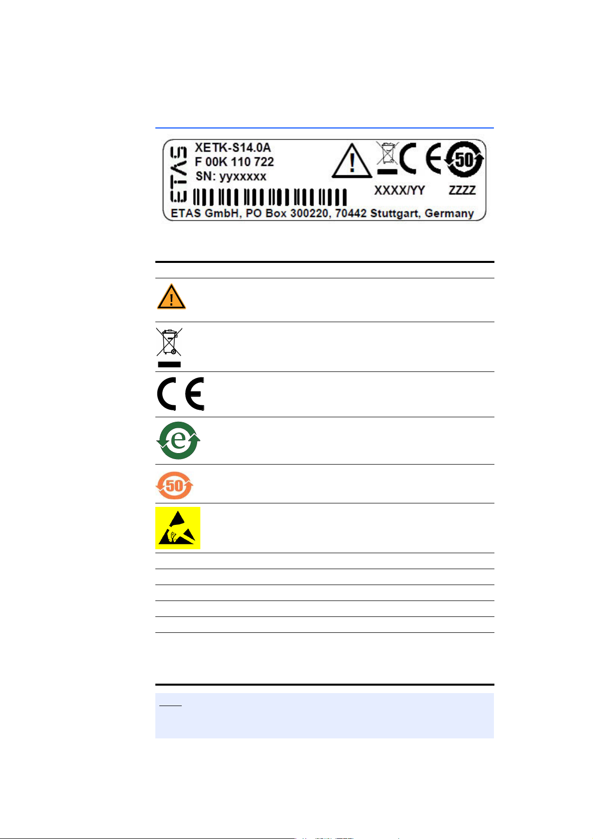
2.4 Identifications on the Product
Fig. 2-1 Adhesive Label (Example: Label for XETK-S14.0)
The following symbols are used for identifications of the product:
Symbol Description
The User's Guide must be read prior to the startup of the
product!
Symbol for WEEE, see chapter 2.5 on page 13
Symbol for CE conformity, see chapter 2.6 on page 13
Symbol for China RoHS, see chapter 2.7.2 on page 13
Symbol for China RoHS, see chapter 2.7.2 on page 13
Symbol for electrostatic sensitive components
XETK-S14.0A Product designation (example)
F 00K 110 722 Order number of the product (example)
SN: yyxxxxx Serial number (7-digit)
XXXX/YY Product version
ZZZZ Year of manufacture
ETAS GmbH,
PO Box 300220,
704
42 Stuttgart,
Germany
Manufacturer's address
For symbols and product information one or several adhesive labels can be
used.
XETK-V2.0 - User’s Guide 12

ETAS Basic Safety Notices
2.5 Taking the Product Back and Recycling
The European Union has passed a directive called Waste Electrical and Electronic
Equipment, or WEEE for short, to ensure that systems are setup throughout the
EU for the collection, treating and recycling of electronic waste.
This ensures that the devices are recycled in a resource-savi
no danger to health or the environment.
Fig. 2-2 WEEE-Symbol
The WEEE symbol (see Fig. 2-2 on page 13) on the product or its packaging
shows that the product must not be disposed of as residual garbage.
The user is obliged to collect the old devic
WEEE take-back system for recycling. The WEEE directive concerns all ETAS
devices but not external cables or batteries.
For more information on the ETAS GmbH Recycli
sales and service locations.
es separately and return them to the
ng software, contact the ETAS
ng way representing
2.6 CE marking
With the CE mark attached to the product or its packaging, ETAS confirms that
the product corresponds to the applicable product-specific European Directives.
The CE Declaration of Conformity for the product is available upon request.
2.7 RoHS Conformity
2.7.1 European Union
The EU Directive 2011/65/EU limits the use of certain dangerous materials for
electrical and electronic devices (RoHS conformity).
This product does not contain any of the restricted substances specified in the EU
Dir
ective 2011/65/EU or exceeds the maximum concentrations stipulated
therein. For individual electronic components used in our products, there are currently no equivalent alternative substanc
exceptions 7A and 7C-I in Annex III of this Directive.
ETAS confirms that the product corresponds
in the European Union.
2.7.2 China
ETAS confirms that the product meets the product-specific applicable guidelines
of the China RoHS (Management Methods for Controlling Pollution Caused by
Electronic Information Products Regulation) applicable in China with the China
RoHS marking affixed to the product or its packaging.
es, which is why we make use of the
to this directive which is applicable
XETK-V2.0 - User’s Guide 13

ETAS Basic Safety Notices
2.8 Declarable Substances
European Union
Some products from ETAS GmbH (e.g. modules, boards, cables) use components
with substances that are subject to declaration in accordance with the REACH
regulation (EU) no.1907/2006.
Detailed information is located in the ETAS download center in the customer
information "REACH Declaration" (
continuously being updated.
www.etas.com/Reach). This information is
2.9 Use of Open Source Software
The product uses Open Source Software (OSS). This software is installed in the
product at the time of delivery and does not have to be installed or updated by
the user. Reference shall be made to the use of the software in order to fulfill
OSS licensing terms. Additional information is available in the document "OSS
Attributions List" at the ETAS website www.etas.com.
XETK-V2.0 - User’s Guide 14
ETAS Introduction
Note
Note
3 Introduction
This section contains general safety instructions, information about the basic features and applications of the XETK-V2.0 Interface
Probe), hints to system requirements, and delivery scope.
Board (ETK = Emulator Test
3.1 Applications
The XETK-V2.0 is an emulator probe for the Freescale MPC5600 microcontroller
family and ST SPC5600 microcontroller family using the Nexus debug interface
(IEEE/ISTO 5001). To cover the multiple microcontroller packaging options, the
XETK-V2.0 is available in three variants: the XETK-V2.0A, XETK-V2.0B, and
XETK-V2.0C.
The XETK-V2.0A/C combines a typical (X)ETK seria
and is based on the VertiCal interface concept from Freescale and ETAS. It can be
used with the above microcontrollers packaged with a Vertical Base Board.
The XETK-V2.0B is a typical (X)ETK serial interface and is suitable for the above
micr
ocontrollers in all packages.
l interface with a 32 bit SRAM
Refer to chapter 7.1.3 on page 50 for a list of supported microcontrollers and
the required software versions to use them.
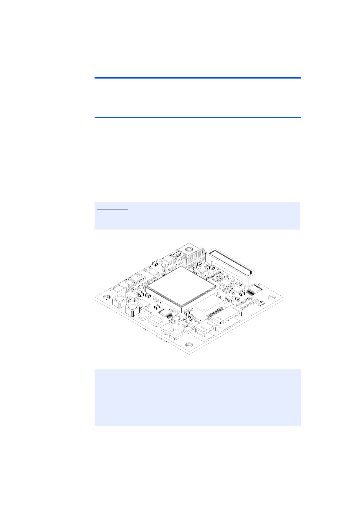
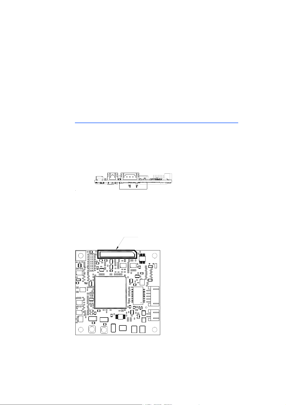
Fig. 3-1 XETK-V2.0 top view
The XETK-V2.0 can be ordered in three different functional and mechanical
variants: XETK-V2.0A, XETK-V2.0B, and XETK-V2.0C. Within the manual the
term "XETK-V2.0" describes features common to all variants. The term "XETKV2.0A/C" describes specific features common to the XETK-V2.0A and XETKV2.0C variants. The term "XETK-V2.0B" describe features specific to the XETKV2.0B variant.
XETK-V2.0 - User’s Guide 15

ETAS Introduction
The XETK-V2.0’s Nexus (JTAG) debug interface at 2.5 V or 3.3 V. The XETK-V2.0
performs measurement and calibration of variables as well as flashing via the
JTAG portion of the Nexus interface. Additionally the Nexus Auxiliary interface
can be used for high speed trace measurement.
The XETK-V2.0A/C provides a Synchronous RAM (SRAM) that can be used by the
ECU to store calibration or other ECU variables (XETK-V2.0A provides 2 MByte
SRAM, XETK-V2.0C provides 4 MByte SRAM). This SRAM is only accessible to the
XETK-V2.0A/C via the microcontroller’s Nexus (JTAG) debug interface. This inter
face operates at 2.5 V or 3.3 V.
The XETK-V2.0 supports the standard full duplex 100Base-T Ethernet interface
and be connected directly or via ES51x/ES59x/ES600 modules to the PC. No addi
tional ETAS modules are required for the access to the ECU. The XETK-V2.0 can
be used for rapid prototyping applications (bypass) as well as for measurement
and calibration applications.
3.2 Features
• Measurement Interface
– Nexus / JTAG interface (operates at 2.5 V or 3.3 V)
– Configurable JTAG interface clock speed: 20 MHz, 30 MHz, or
40
MHz
– Nexus Trace interface clock speed: up to 66 MHz
– Supports coldstart measurement mechanism
– Supports high speed measurement rasters with Nexus Trace (down to
10 μs)
– Hardware synchronization and time stamping
• Startup protocol for XETK / ECU synchronization
– DAI pins (all microcontrollers)
– Pinless via Nexus / JTAG
• Trigger interface
– 2 DAI triggers
– 32 Pinless triggers via Nexus / JTAG
– 4 triggers generated by internal timers
– 16 trace triggers
– 64 total measurement rasters
• Calibration interface
– XETK-V2.0A/C provides SRAM to be used for emulation data with a
configurable chip select
– XETK-V2.0A/C provides power for both the Microcontroller External
Bus Interface and the on board XETK RAM
– Microcontroller capability of re-mapping Flash to RAM emulation used
by ECU software
– Supports “Start on Working Page”
• Debugger interface
– XETK-V2.0 arbitration possible with "Lauterbach Power Trace"
-
-
XETK-V2.0 - User’s Guide 16

ETAS Introduction
– XETK-V2.0A/C provides additional Nexus (JTAG) compliant Samtec
connector for external debug hardware
– XETK-V2.0B hardware is prepared to be used simultaneously with a
debugger, but an additional external arbitration circuit and debugger
connection is required
• ECU flashing via XETK
– Braindead flashing under ProF control
• XETK-V2.0A/C VertiCal interface
– Small form factor
– Short signal lines for minimal impedance
– Applicable for multiplexed 32-bit microcontroller bus
– Supports 32-, 16- and 8-bit access to the provided memory
– VertiCal Shroud installed to aid in alignment during product installa-
tion
• Fast Ethernet interface
– Direct connection to PC
– Open XCP on Ethernet protocol
– Supports a variety of standard applications
• Firmware update (programming of the logic device) through service software "Hardware Service Pack" (HSP); removal of XETK or ECU not necessary
• Temperature range suitable for automotive application
• Permanent storage of configuration in EEPROM
For more technical data on the XETK-V2.0 consult the chapter "Technical Data"
on page 50.
XETK-V2.0 - User’s Guide 17

ETAS Hardware Description
Note
4 Hardware Description
In this chapter, the function blocks of the XETK-V2.0 are explained in detail.
The XETK-V2.0 can be ordered in three different functional and mechanical
variants: XETK-V2.0A, XETK-V2.0B, and XETK-V2.0C. Within the manual the
term "XETK-V2.0" describes features common to all variants. The term "XETKV2.0A/C" describes specific features common to the XETK-V2.0A and XETKV2.0C variants. The term "XETK-V2.0B" describe features specific to the XETKV2.0B variant.
4.1 Overview
4.1.1 XETK-V2.0 Variants
The XETK-V2.0 can be ordered in three different functional and mechanical variants: XETK-V2.0A, XETK-V2.0B, and XETK-V2.0C. The pri
between the XETK-V2.0 variants are described below.
mary differences
XETK-V2.0A/C XETK-V2.0B
ECU Connection 156 pin VertiCal 50 pin Samtec to ETAHx
Ad
apter:
ETAH1 - 38 pin Mictor
Calibration RAM 2 / 4 MByte SRAM pro-
Provided by ECU
1)
vided on XETK
Debugger Connection 50 pin Samtec None
Supported Microcontrol-
Vertical Base Board All Packages (e.g. Produc-
ler Packages
Installation Mounting VertiCal Base Board,
ad
ditionally 4 mounting
holes
JTAG / Nexus Interface Minimal signal condition-
ing on ECU (direct from
iCal Base Board)
Vert
Trigger Pin Connection Microcontroller GPIO via
D
AI circuit back to Verti-
Cal Base Board optional
3
ECU Switched Power
oring (Ignition /
Monit
ball locations
Built into VertiCal Base
Board
2)
tion Package or Vertical
ase Board)
B
Internal ECU housing or
ECU pcb using 4 mounting holes
Signal Conditioning
required on
ECU
microcontroller GPIO via
DAI circuit to XETK ECU
connector
Route signal to XETK ECU
connector
microcontroller power)
Standby Power Monitoring (Validity of Calibra-
Built into XETK Route signal to XETK ECU
conn
ector
tion RAM)
XETK-V2.0 - User’s Guide 18
ETAS Hardware Description
XETK-V2.0A/C XETK-V2.0B
Watchdog Timer Disable ECU circuit back to Verti-
Cal Base Board optional
ball location
3)
ECU circuit back to XETK
ECU connector
Dimension (H/W/D) 12 / 60 / 60 mm 9 / 60 / 60 mm
1)
: ECU application specific: internal or external RAM
2)
: XETK-V2.0B hardware is prepared to be used simultaneously with a debug-
ger (additional external arbitration circu
3)
: For ECUs with BGA adapters, VertiCal Base Boards with optional balls are
it and debugger connection is required).
required to use the DAI startup/ triggering and Watchdog Timer Disable features of the XETK-V2.0A/C.
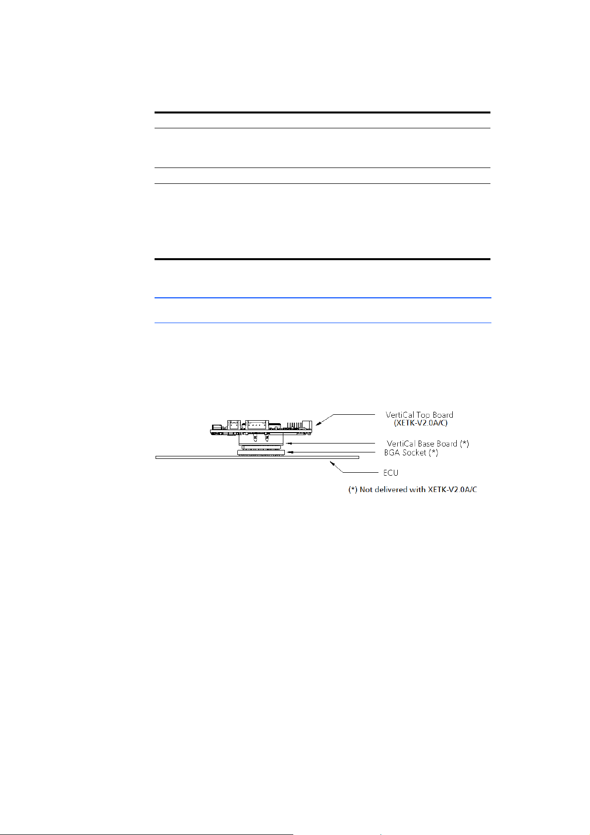
4.1.2 XETK-V2.0A/C VertiCal Interface Concept
Overview
The XETK-V2.0A/C uses the VertiCal interface concept to connect to the development ECU. The VertiCal Base Board uses a
age (CSP), which is fully compatible to
microcontroller in a chip scale pack-
the standard microcontroller.
With the VertiCal interface, the microcontroller of the ECU is not mounted on
t
he ECU or XETK, but on an additional board, the VertiCal Base Board.
Fig. 4-1 VertiCal Interface Concept (Side View)
The complete XETK-V2.0A/C VertiCal solution and its components are mounted
o
n two different boards:
• The VertiCal Base Board with
– a microcontroller in chip scale package (CSP)
– VertiCal connector (provides access to the ECU microcontroller adapter
and t
he VertiCal top board)
– a Pin Array / BGA / QFP Adapter to plug
the base board into the ECU
• The VertiCal Top Board (XETK-V2.0A/C) with
– Ethernet interface (converts microcontrolle
r signals into tool interface)
–2 MByte SRAM for XETK-V2.0A or 4 MByte for XETK-V2.0C
– Samtec connector with Nexus (JTAG) in
terface for a debugger
XETK-V2.0 - User’s Guide 19
ETAS Hardware Description
mкбенЙЗ=`бкЕмбн=_з~кЗ
sЙкнб`~д=`зееЙЕнзк
jбЕкзЕзенкзддЙк
mкбенЙЗ=`бкЕмбн=_з~кЗ
sЙкнб`~д=`зееЙЕнзк
máå=^êê~óL
_d^=^Ç~éíÉê
Note
Note
– VertiCal Shroud installed around the VertiCal connector to aid in align-
ment during product installation
For ECUs with BGA adapters VertiCal Base Boards with optional balls are
required to use the DAI startup/ triggering and Watchdog Timer Disable fea
-
tures of the XETK-V2.0A/C.
For ECUs with QFP adapters the DAI startup/triggering is already considered in
the VertiCal Base Board. The Watchdog Timer Disable feature of the XETKV2.0A/C is not available.
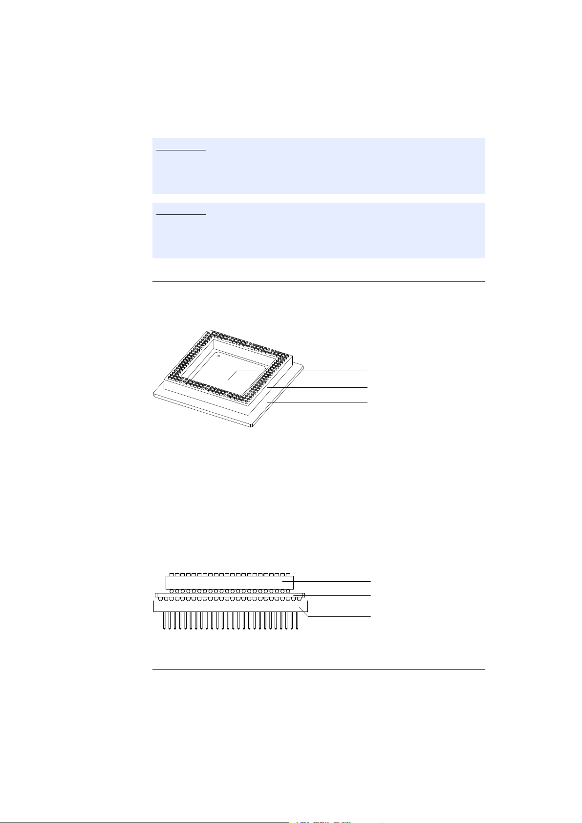
VertiCal Base Board
The printed circuit board (PCB), one of the VertiCal base board components, is
used as a base to mount the other components of the VertiCal Base Board.
Fig. 4-2 VertiCal Base Board
The upper side of the printed circuit board is assembled with
• the microcontroller device (packaged into the
specified CSP package),
• the VertiCal connector (standardized 156-way connector).
The lower side of the printed circuit board has a footprint similar to that used by
MPC5
600 family devices in standard production packages. It is populated with a
"BGA adapter" connector allowing connection and removal from an ECU development PCB which has been populated with
a compatible "BGA receiver"
socket (see Fig. 4-3).
Fig. 4-3 VertiCal Base Board (fitted with Pin Array/ BGA Adapter, Side View)
Typical Usage
The standard ECU microcontroller is replaced by the VertiCal base board with the
same dimensions and the same pinout.
The VertiCal base board connects the
ECU with the XETK-V2.0A/C.
XETK-V2.0 - User’s Guide 20
ETAS Hardware Description
XCP on
Ethernet Interface
SRAM
System
Functions
Trigger
Unit
100
MBit/s
Ethernet
Phyter
Ethernet
Phy
Automatic
Power On
Ethernet
Traffic
Detection
Ethernet
Traffic
Detection
Sense ECU
Power Supplies
ECU
Reset
Power
Supply
Monitoring
Standby Power Supply
ECU
Reset &
Power
Control
DMA
MCU
Core
Ethernet
MAC
Measurement &
Calibration
Unit
ECU
Access
Unit
Serial Flash
Configuration &
Manufacturing
Data
Time
Sync.
Trace
Functions
SRAM
Nexus / JTAG
DAI Pins
U- BattU- Batt
Power
Supply
4.3V...36V
Standby
Supply
4.3V...36V
Power
159
Pin
VertiCa
l
Connecto
r
VertiCal
Connector
(ECU Interface)
Nexus
Aux.
Nexus SAMTEC
Connector
(Debugger)
JTAG
Arbitration
SRAM
XETK-V2.0A – 2 MB
XETK-V2.0C – 4 MB
(Data Working Page
+ Measurement)
EBI Power Supply
XETK-V2.0
BA/C
Nexus SAMTEC
Connector
(ECU Interface)
4.1.3 XETK-V2.0B Interface Concept
The XETK-V2.0B connects to the ECU in a similar manner to other serial (X)ETKs,
using a cable with a standard debugging interface connector. The XETK-V2.0B is
equipped with a 50 pin Nexus Samtec connector and connects to the ECU using
an ETAHx ECU adapter cable.
The ETAH1 ECU adapter cable offers a connection to an EC
U equipped with a 38
pin Mictor connector. Other ETAHx variants are possible.
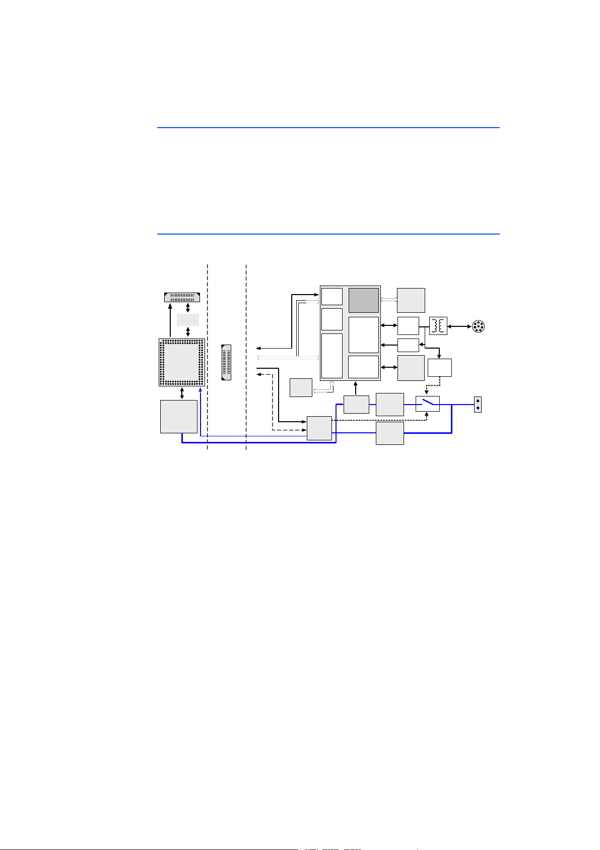
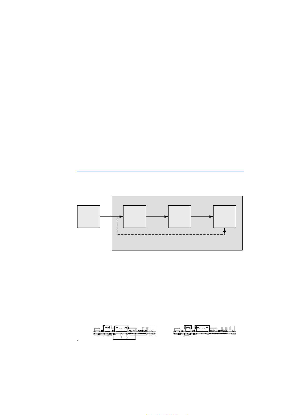
4.2 Architecture
Fig. 4-4 XETK-V2.0 Architecture
The XETK-V2.0’s primary interface to the
development ECU is the Nexus / JTAG
interface of the microcontroller. This interface is available at the VertiCal connector of the XETK-V2.0A/C or the Samtec co
face provides the XETK access to the same m
nnector of the XETK-V2.0B. This inter-
emories accessible to the
microcontroller, including both internal and/or external Flash and/or RAM. The
XETK-V2.0 can only access these memories while the microcontroller is powered
and out of reset.
The XETK-V2.0A/C provides a SRAM the developm
lation memory and/or as measuremen
t data memory. The XETK-V2.0A/C
ent ECU can use as data emu-
accesses this SRAM in the same way as other development ECU memories, via
the microcontroller’s Nexus /JTAG interface.
While the microcontroller accesses the program dat
a (not the program code) out
of the data emulation memory provided by either the XETK-V2.0A/C or the ECU,
the content of the data emulation memory can simultaneously be modified by
the calibration and development system through the XETK Ethernet interface.
This process enables adjustments of parameters, characteristic lines and maps
through the calibration and development system. Using an additional measurement data memory area, the ECU microcontroller can provide data to the calibration and development system by buffering the data (DISTAB13) and triggering
XETK to read the data via JTAG. The XETK then reads, buffers, processes and
the
sends this measured data to the PC.
XETK-V2.0 - User’s Guide 21
ETAS Hardware Description
`lkN
`lkO
ON R
N
`lkQ
`lkR
If no additional measurement data memory is available, the XETK-V2.0 can alternatively read the data to be measured directly from the microcontroller’s memory. This process is Triggered Direct M
The XETK-V2.0 can also receive the data to
easurement (TDM) with DISTAB13.
be measured via the Nexus Auxiliary
interface using data trace windows and trace triggering. The data trace can be
used with or without DISTAB13.
The 100 Mbit/s XETK Ethernet interface provides communication with the PC.
The power supply for the XETK-V2.0 is provided by a switch mode power supply,
to
minimize power dissipation.
4.3 ECU Interface
The XETK-V2.0A/C and XETK-V2.0B utilize different connectors of the XETKV2.0 as the ECU interface.
The XETK-V2.0A/C interfaces to the microcontroller via the VertiCal connector,
CO
N1 (refer to Fig. 4-6 on page 22). The interface provides access to
controller’s external bus and Nexus (JTAG
) interface.
the micro-
Fig. 4-5 XETK-V2.0A/C ECU Interface CON1
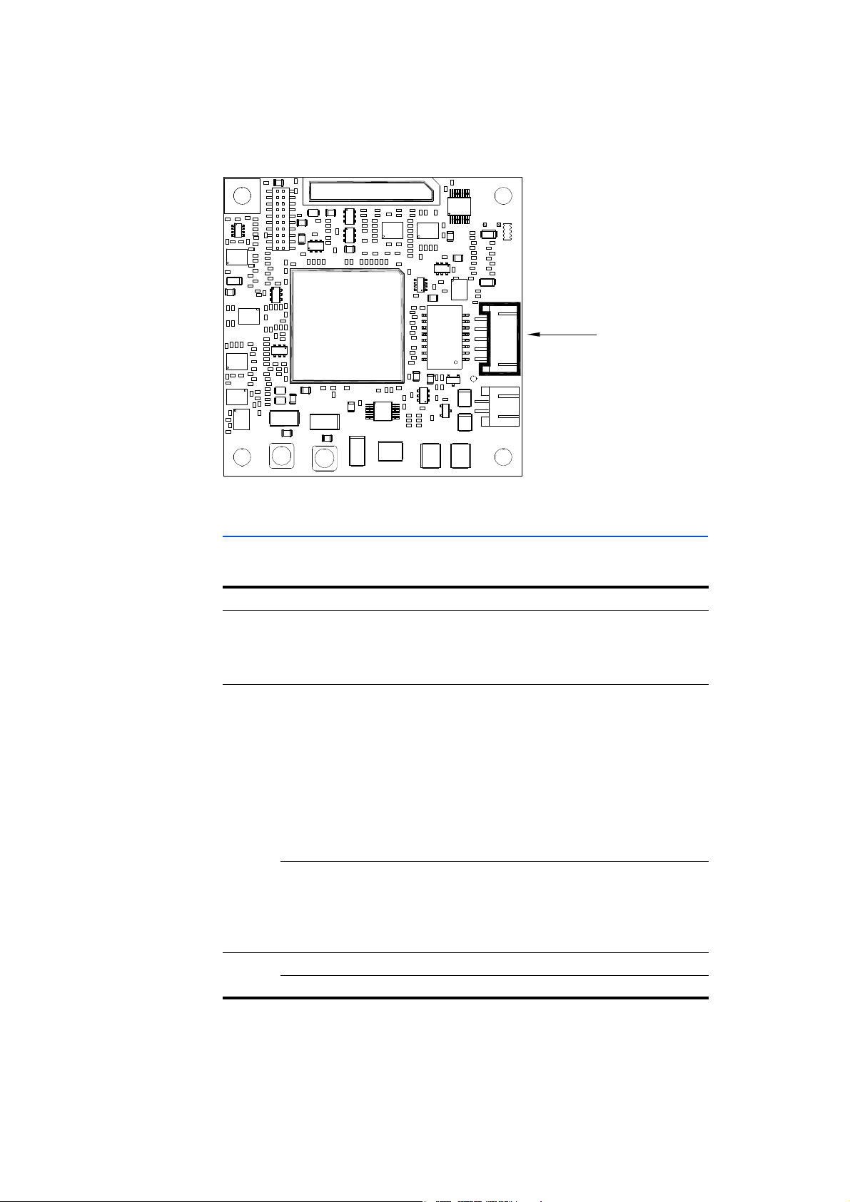
The XETK-V2.0B interfaces to the microcontroller via the Samtec connector,
CO
N5 (refer to Fig. 4-6 on page 22). The interface provides access to
the micro-
controller’s Nexus (JTAG) interface.
Fig. 4-6 XETK-V2.0B ECU Interface CON5
XETK-V2.0 - User’s Guide 22
ETAS Hardware Description
b`r=mçïÉê
pмййду
jáÅêçJ
ЕзенкзддЙк
bqh`~к=_~ннЙку
r_^qq s`` s``
b`r
`lkN
`lkO
ON R
N
`lkQ
`lkO
ON R
N
`lkQ
For a complete list of the pins of the XETK-V2.0A/C ECU interface refer to
section 7.11.1 on page 72 and to section 7.11.3 on page 79 for the XETK-V2.0B
ECU Interface. In general the interface of each device consists of:
• ECU voltage lines, which are not used for powering the XETK, but for
de
tecting the ECU status; therefore the power consumption on these lines
is negligible (refer to chapter 4.4 on page 23)
• Data Acquisition Interrupt lines (DAI
lines) which are used for XETK synchronization at startup and for Data Acquisition (refer to chapter 4.11.4
and 4.11.5)
• Reset lines which allow the XETK to bot
h monitor and control the system
reset of the ECU (refer to chapter 4.7 on page 26)
• JTAG Interface used as the measur
ement and calibration interface
between the XETK-V2.0 and the microcontroller (refer to chapter 4.9
on page 29)
• Nexus Auxiliary Interface used as an optional mea
surement interface
between the XETK-V2.0 and the microcontroller
4.4 Power Supply
The XETK-V2.0 needs a permanent power supply. It is powered directly from the
car battery. The input voltage may vary between 4.3 V and 36 V
Fig. 4-7 Power Supply monitoring
All necessary voltages required by the XETK
are created through switching power
supplies which minimizes heat build-up. The power supply of the ECU is not
affected by the XETK-V2.0. An automatic switch ensures that the power supply
of the XETK-V2.0 is automatically switched on and off. The ECU voltage VCC
(V_RESET for XETK-V2.0A/C and V_NEXUS for XETK-V2.0B) is monitored by the
XETK to recognize whether the ECU is switched on or off.
The XETK-V2.0 must be supplied with power through the 2-pin power supply
nector CON2 in Fig. 4-8 below.
con
Fig. 4-8 Power Supply Connector CON2 (left: XETK-V2.0A/C, right: XETK-
V2.0B)
XETK-V2.0 - User’s Guide 23
ETAS Hardware Description
`lkO
`lkP
Note
Pin CON2 Signal Description
1 U
2 GND Ground
Batt
Battery Supply Voltage for XETK
Additionally the through-hole solder pad CON3
supply U
Fig. 4-9 Power Supply Connectors CON2 and CON3
. The power supply on CON3 must use the GND of CON2.
Batt2
can be used to connect a power
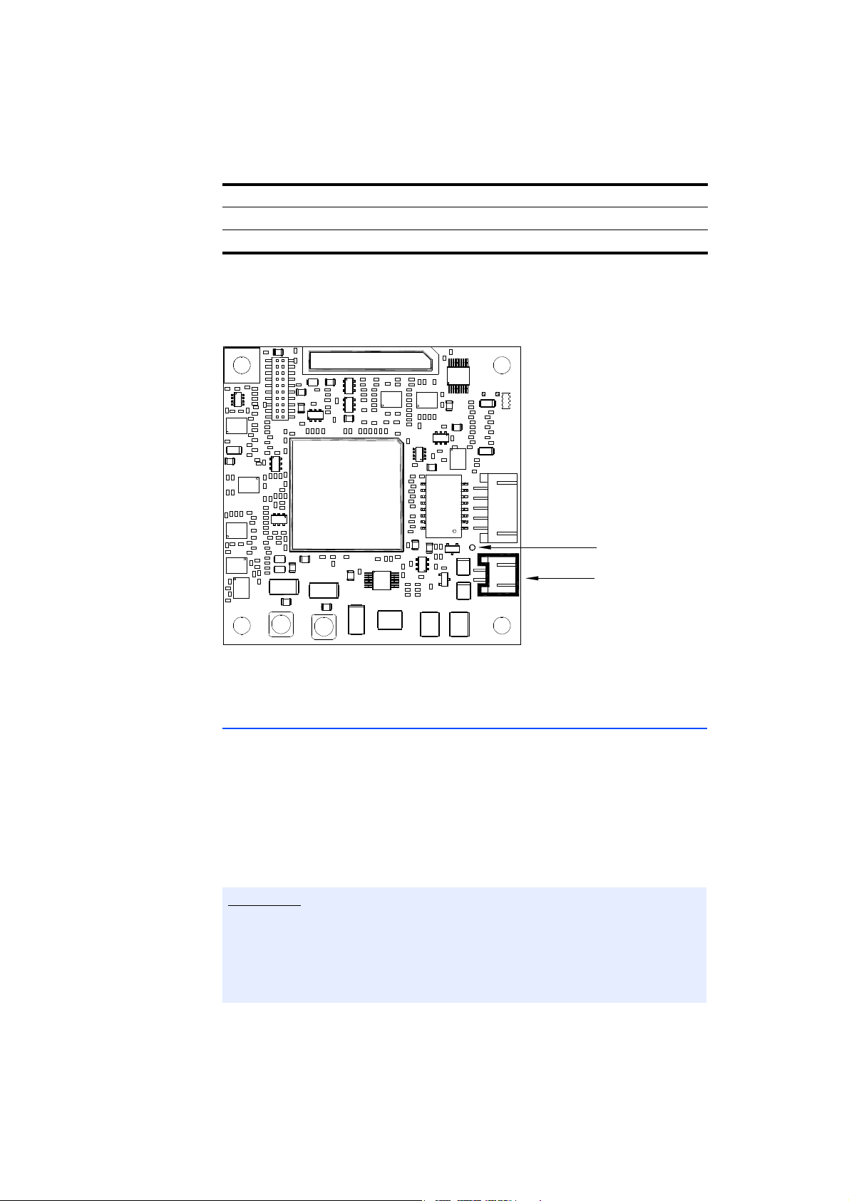
4.5 XETK Ethernet Interface
The XETK Ethernet interface shown in Fig. 4-10 can be directly connected to the
PC. No additional ETAS module is r
The interface is a standard full duplex 10
XCP protocol. The XETK Ethernet interface is integrated in the ETAS IP world with
automatic IP management and supports the open automotive "Universal Measurement and Calibration" standard "XCP
open XCP on Ethernet interface allows for connecting to the XETK-V2.0 with
third party application software.
The XETK Ethernet interface is not compatible with the ETK interfaces in modules like e.g. ES910, ES590, ES591,
The XETK Ethernet interface is compatible with the ECU interface of the ES910
module and the Ethernet interfaces of the ES51x/ ES592/ ES593-D/ ES595/
ES600 modules.
The maximum length of the interface cable is specified for 30 m.
equired for the access to the ECU.
0Base-TX Ethernet interface using the
on Ethernet" (TCP/IP, UDP/IP). The
ES592, ES593-D, ES595, ES1232-A.
XETK-V2.0 - User’s Guide 24
`lkQ
ETAS Hardware Description
Fig. 4-10 Location of the Ethernet Interface CON4
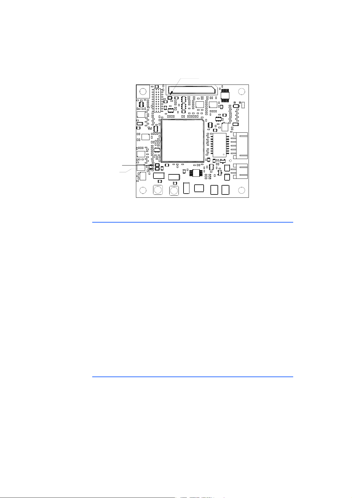
4.6 Status LEDs
There are three LEDs displaying the operating status of the XETK-V2.0 (Fig. 4-11
on page 26).
LED State Meaning
Red On XETK-V2.0 is supplied with power and active (i.e. the ECU is
Green On Power supply has dropped under 4.3V (XETK-V2.0A/C) or
Off Working page may be different to
swit
ched on or the ETAS calibration and development sys-
tem is connected and ready to communicate with the XETK-
)
V2.0
th
e selected standby threshold (XETK-V2.0B):
- data retention of the calibration data in the XETK-V2.0A/C
RAM or the ECU RAM monitored by the XETK-V2.0B is no
S
longer ensured
- as soon as ECU switches on again, it should switch to the
nce Page.
Refere
Green LED stays lit until the calibration and development
em downloads data into the calibration data memory.
syst
Until then switching to the Working Page is not possible.
reference page. Calibra-
tion and development system has downloaded data since
he last power failure. Switching between the Reference
t
Page and Working Page is possible.
Yellow On 100 Mbit/s link to calibration system established
Flashing Communication active
XETK-V2.0 - User’s Guide 25
iba=êÉÇ
iba=уЙддзп
iba=ЦкЙЙе
ETAS Hardware Description
Fig. 4-11 Status LEDs
4.7 Reset
The requirement for XETK reset mechanism is to ensure that power-up and
power-down behavior of ECU is clean and to prevent corruption of data stored
in the XETK-V2.0A/C’s SRAM.
To accomplish this the XETK-V2.0 senses the microcontroller power supply at the
E
CU interface connection; V_RESET of the XETK-V2.0A/C and V_NEXUS of the
XETK-V2.0B. This allows the XETK to detect when the ECU is off and forward this
information to INCA. In addition, it allows the XETK to enter the power save
mode if the ECU is off and the PC is off or unplugged.
Furthermore, the XETK-V2.0 se
write protect signal for its memory. If configured, the /RSTOUT line can also be
used to sense the status of the ECU reset.
Finally, the XETK-V2.0 generates a reset signal
in reset while the XETK is in power save mode and to prevent the microcontroller
from starting until the XETK is ready to work.
The XETK is ready to work when it has finished
power save mode or after initial power-up. This feature allows it also to reset the
ECU under tool control (required for INCA and ProF) and to perform an emergency stop of the ECU in case of XETK failure.
4.8 Data Emulation Memory
The XETK-V2.0 is a serial XETK using JTAG / Nexus as its primary microcontroller
interface. Typical of all serial XETKs, the RAM used for data emulation and data
measurement is not accessible by the XETK until the microcontroller is powered
up and the startup handshake is performed. This includes the 2 MByte of SRAM
pr
As with parallel XETKs, serial XETKs have a
and a Working Page (ETAS two page XETK concept).
ovided on the XETK-V2.0A or the 4 MByte provided on the XETK-V2.0C.
nses the status of the /RESET line to generate a
by pulling /RESET to keep the ECU
its initialization after leaving
system consisting of both a Reference
XETK-V2.0 - User’s Guide 26

ETAS Hardware Description
Note
The Reference Page is located in the ECU flash and can not be modified by a
simple write access. All changes to the Reference Page must be done via Flash
programming. The INCA user can use ProF to invoke a customized flash programming algorithm.
When using the XETK-V2.0A/C, the Working Page should be located within the
ETK-V2.0A/C’s on board SRAM. The Working Page may be a portion of or the
X
entire size of this RAM. To make the Working Page accessible to the XETKV2.0A/C, the microcontroller software must configure the external bus interface
correctly.
When using the XETK-V2.0B, the Work
nal or external RAM of the ECU. It is recomm
powered.
Another important restriction is that no access to
the ECU is not running. To enable a cold start measurement in spite of this
restriction, a special procedure is defined to give the user the feeling of a parallel
XETK.
Because there is no write protection of the data emulation memory possible,
the user must be take care not to overwrite emulation data.
ing Page may be located in either a inter-
ended that this RAM is permanently
the memory is possible, while
4.8.1 Page Switching
To enable calibration, the Working Page must be activated. The process of
switching from the Reference Page to the Working Page and vice versa is known
as page switching. The XETK-V2.0 supports two methods of page switching;
however, one method is only available for certain microcontrollers.
Regardless of which page switch method is used and which page is activated
rom the microcontroller’s point of view, both the Reference Page and Working
f
Page are accessible for standard operations using INCA such as upload or checksum calculations.
Protocol Based
The XETK-V2.0 supports Protocol Based page switching for all supported microcontrollers. Switching between Reference and Working Page is done in microcontroller software by re-directing accesses to calibration data between either
Flash (Reference Page) or the RAM (Working Page) using microcontroller
the
internal mechanisms. The XETK-V2.0 does not directly control the microcontroller mechanism used to do this re-direction. Instead the XETK-V2.0 and microcontroller software share a mailbox in RAM. The XETK use
and monitor page switching; the microcontroller is responsible to service this
mailbox and perform the page switches.
Direct Register Access
The XETK-V2.0 supports Direct Register Access page switching for microcontrollers which provide additional internal registers for page switching. Switching
etween Reference and Working Page is done in microcontroller hardware by re-
b
s this mailbox to request
XETK-V2.0 - User’s Guide 27

ETAS Hardware Description
Note
Note
Note
Note
directing accesses to calibration data between either the Flash (Reference Page)
or the RAM (Working Page) using microcontroller internal registers. The XETKV2.0 has direct access to control these registers.
To use Direct Register Access page switch
initialize the necessary registers; however, it must not change the values after the
XETK startup handshake has taken place.
The XETK-V2.0 can use the Direct Register Access page switch method with
the MPC5676R, MPC5644A, SPC564A80, and MPC5777C.
4.8.2 XETK-V2.0A/C SRAM Characteristics & Data Retention
The XETK-V2.0A’s SRAM is 2 MBytes, 32 x 512 kBytes. The XETK-V2.0C’s SRAM
is 4 MBytes, 32 x 1024 kBytes. It is a synchronous memor
VertiCal Base Board supporting 32 bit multiplexed mode or 16 bit non multiplexed mode using the configuration feature "Calibration Bus Data Width". The
16 bit non multiplexed mode setting can only be configured for microcontrollers
at do not support 32 bit multiplexed mode; otherwise 32 bit multiplexed mode
th
t be used.
mus
ing the microcontroller software must
y connected to the
In 16 bit mode, the XETK-V2.0A/C’s SRAM is only 1 MByte, 16 x 512 kBytes.
In multiplexed mode during the address cycle of a read or wr
Address pins are used as Address. The address is latched into the SRAM during
this cycle using CLKOUT and /TS. During the data cycle of a read or write access
the Address and Data pins both contain data to create the 32 bit data bus.
The XETK-V2.0A/C’s SRAM is powered by the same power that is supplied to the
ETK-V2.0A/C. To guarantee that data in the SRAM is preserved even when the
X
ignition is switched off, the XETK-V2.0A/C must be permanently supplied with
power from the car battery. If the ECU with XETK-V2.0A/C is disconnected from
the battery, all data in the SRAM is not guaranteed and may be lost.
The XETK-V2.0A/C’s SRAM content is not ba
Working Page data in the SRAM permanently to the ECU, the INCA user can use
ProF to invoke a customized flash programming algorithm to store the content
of the Working Page to the Reference Page in Flash.
To access the XETK-V2.0A/C’s SRAM the microcontroller software must configure the microcontroller’s external bus interface for either multiplexed or non
multiple
for 32 bit (multiplexed) accesses or for 16 bit (non multiplexed) accesses. Additionally the VertiCal Base Board may require configuration by hardware solder
br
xed mode. The chip select for the XETK-V2.0A/C must be configured
idges to select 32 bit (multiplexed) or for 16 bit (non multiplexed).
cked up in a data flash. To store the
ite access the
The XETK-V2.0A/C does not support burst accesses to this SRAM.
XETK-V2.0 - User’s Guide 28

ETAS Hardware Description
Microcontroller
(VertiCal Base Board)
TDO
TDO
/RDY
/RDY
/TRST
TDI
R >=100k
or Pullup
TDI
/TRST
TMS
TCK
TMS
1k 1k
TCK
ECU XETK
22
22
22
22
1k
V_NEXUS
XETK
System
Controller
MDO[15..0]
/MSEO[1..0]
/EVTO
MDO[15..0]
/MSEO[1..0]
/EVTO
/EVTI
/EVTI
22
MCKO
MCKO
VertiCal
Connector
Other ECU
JTAG / Nexus
Connectors
not present
not present
not present
not present
not present
not present
not present
not present
not present
Note
4.8.3 Data Emulation Power Failures
The XETK-V2.0 has a circuit which recognizes and stores power failures. The
XETK-V2.0 will notify the microcontroller software of the power failure using the
DAI pins and additionally will prevent the user from switching to the working
page until the PC software has downloaded a new Working Page data into the
data emulation memory.
The calibration feature "start on working page" or "start on last active page
with the last active page being the working page" is only possible when the
working page has been downloaded since the last power failure. Until a down
load occurs after a power failure the micro
controller software is informed of a
power failure by the DAI pins and is responsible to make the reference page
active.
4.9 Nexus (JTAG) Interface
-
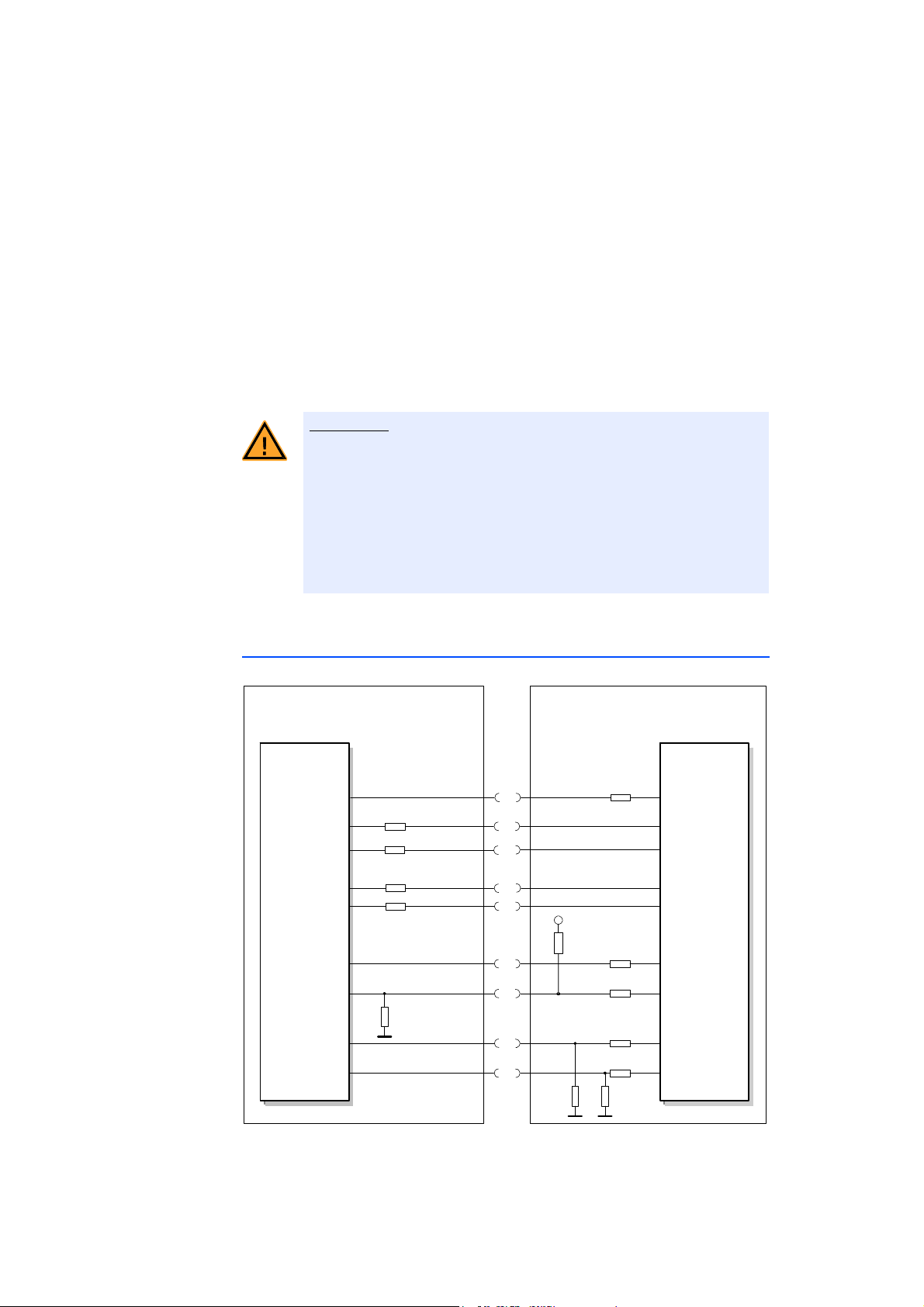
4.9.1 XETK-V2.0A/C
Fig. 4-12 Equivalent Circuitry of the XETK-V2.0A/C Nexus (JTAG) Interface
The ECU part of the XETK-V2.0A/C Nexus (JTAG
Fig. 4-12. The XETK incorporates 22 Ohm series resistors for the TDI, /TRST, TCK,
and TMS lines on the ECU interface. Additional pull ups / downs are as shown.
XETK-V2.0 - User’s Guide 29
) interface is depicted in
ETAS Hardware Description
Micro -
controller
TDO
TDO
/RDY /RDY
/TRST
TDI
R >=100k
or Pullup
TDI
/TRST
TMS
TCK
TMS
1k 1k
TCK
ECU XETK
44
44
44
44
1k
V_NEXUS
XETK
System
Controller
MDO[15..0]
/MSEO[1..0]
/EVTO
MDO[15..0]
/MSEO[1..0]
/EVTO
/EVTI
/EVTI
22
MCKO MCKO
ECU Specific
ECU Specific
ECU Specific
ECU Specific
CAUTION!
The microcontroller is mounted directly on the VertiCal Base Board; therefore it
is not possible to add additional series resistors between the microcontroller and
XETK for TDO, /RDY, /EVTO, MCKO, MDOx, and /MSEOx.
When the ECU design incorporates JTAG /
Nexus connectors, additional circuitry
is required to ensure these connectors and the signal routing do not influence
the interface between the microcontroller and XETK. The ECU must incorporate
0 Ohm series resistors on every signal which goe
s to an additional JTAG / Nexus
connection. Additionally, the resistors must be placed as close to the microcontroller as possible; especially for TCK and MCKO. For proper operation of the
ETK-V2.0A/C it is mandatory to depopulate these resistors (e.g. not present), as
X
shown in Fig. 4-12. For ECUs used without the XETK-V2.0A/C, the resistors can
be populated to provide functional JTAG / Nexus connectors.
Risk of damaging the XETK due to short circuiting the JTAG
signals!
When the XETK-V2.0A/C is connected to the ECU, you must ensure
that no other device is actively driving the JTAG signals (TCK, TDI,
TMS) via another connector on the ECU (e.g. Lauterbach debugger
directly on ECU pcb). To use these other tools you must remove the
XETK-V2.0A/C or plug the other tools into the ECU via the XETKV2.0A/C’s NEXUS (JTAG) Debugger Connector.
4.9.2 XETK-V2.0B
Fig. 4-13 Equivalent Circuitry of the XETK-V2.0B Nexus (JTAG) Interface
XETK-V2.0 - User’s Guide 30
 Loading...