

ETAS XETK-S21.0B User Manual

XETK-S21.0B
Emulator Probe for MPC57xx and EMU57xx MCU Family
User’s Guide

Copyright
The data in this document may not be altered or amended without special notification from ETAS GmbH. ETAS GmbH undertakes no further obligation in relation to this document. The software described in it can only be used if the
customer is in possession of a general license agreement or single license. Using
and copying is only allowed in concurrence with the specifications stipulated in
the contract.
Under no circumstances may any part of this document be copied, reproduced,
transmitted, stored in a retrieval system or translated into another language
without the express written permission of ETAS GmbH.
© Copyright 2017 ETAS GmbH, Stuttgart
The names and designations used in this document are trademarks or brands
belonging to the respective owners.
XETK-S21.0B - User’s Guide R04 EN - 05.2017
2

ETAS Contents
Contents
1 About this Manual . . . . . . . . . . . . . . . . . . . . . . . . . . . . . . . . . . . . . . . . . . . . . . . . . 7
1.1 Identification of Safety Notices . . . . . . . . . . . . . . . . . . . . . . . . . . . . . . . . . . . 7
1.2 Presentation of Information . . . . . . . . . . . . . . . . . . . . . . . . . . . . . . . . . . . . . 7
1.3 Scope of Supply . . . . . . . . . . . . . . . . . . . . . . . . . . . . . . . . . . . . . . . . . . . . . . 8
1.4 Additional Information . . . . . . . . . . . . . . . . . . . . . . . . . . . . . . . . . . . . . . . . . 8
2 Basic Safety Notices . . . . . . . . . . . . . . . . . . . . . . . . . . . . . . . . . . . . . . . . . . . . . . . . 9
2.1 General Safety Information . . . . . . . . . . . . . . . . . . . . . . . . . . . . . . . . . . . . . . 9
2.2 Requirements for Users and Duties for Operators . . . . . . . . . . . . . . . . . . . . . 9
2.3 Intended Use . . . . . . . . . . . . . . . . . . . . . . . . . . . . . . . . . . . . . . . . . . . . . . . . 9
2.4 Identifications on the Product . . . . . . . . . . . . . . . . . . . . . . . . . . . . . . . . . . 12
2.5 Taking the Product Back and Recycling . . . . . . . . . . . . . . . . . . . . . . . . . . . . 13
2.6 CE marking . . . . . . . . . . . . . . . . . . . . . . . . . . . . . . . . . . . . . . . . . . . . . . . . . 13
2.7 RoHS Conformity . . . . . . . . . . . . . . . . . . . . . . . . . . . . . . . . . . . . . . . . . . . . 13
2.7.1 European Union . . . . . . . . . . . . . . . . . . . . . . . . . . . . . . . . . . . . . . 13
2.7.2 China . . . . . . . . . . . . . . . . . . . . . . . . . . . . . . . . . . . . . . . . . . . . . . 13
2.8 Declarable Substances . . . . . . . . . . . . . . . . . . . . . . . . . . . . . . . . . . . . . . . . 14
2.9 Use of Open Source Software . . . . . . . . . . . . . . . . . . . . . . . . . . . . . . . . . . . 14
3 Introduction . . . . . . . . . . . . . . . . . . . . . . . . . . . . . . . . . . . . . . . . . . . . . . . . . . . . . 15
3.1 Applications . . . . . . . . . . . . . . . . . . . . . . . . . . . . . . . . . . . . . . . . . . . . . . . . 15
3.2 Features . . . . . . . . . . . . . . . . . . . . . . . . . . . . . . . . . . . . . . . . . . . . . . . . . . . 15
4 Hardware Description . . . . . . . . . . . . . . . . . . . . . . . . . . . . . . . . . . . . . . . . . . . . . . 17
4.1 Architecture . . . . . . . . . . . . . . . . . . . . . . . . . . . . . . . . . . . . . . . . . . . . . . . . 17
4.2 ECU Interface . . . . . . . . . . . . . . . . . . . . . . . . . . . . . . . . . . . . . . . . . . . . . . . 18
4.3 XETK Ethernet Interface . . . . . . . . . . . . . . . . . . . . . . . . . . . . . . . . . . . . . . . 19
4.4 Debug Interface . . . . . . . . . . . . . . . . . . . . . . . . . . . . . . . . . . . . . . . . . . . . . 20
4.5 Power Supply . . . . . . . . . . . . . . . . . . . . . . . . . . . . . . . . . . . . . . . . . . . . . . . 21
4.6 ECU Voltage Supervisor . . . . . . . . . . . . . . . . . . . . . . . . . . . . . . . . . . . . . . . 21
XETK-S21.0B - User’s Guide 3

Contents ETAS
4.7 Status LEDs . . . . . . . . . . . . . . . . . . . . . . . . . . . . . . . . . . . . . . . . . . . . . . . . . 22
4.8 Data Emulation and Data Measurement . . . . . . . . . . . . . . . . . . . . . . . . . . . 23
4.9 JTAG Interface . . . . . . . . . . . . . . . . . . . . . . . . . . . . . . . . . . . . . . . . . . . . . . 24
4.10 Trigger Modes: Overview . . . . . . . . . . . . . . . . . . . . . . . . . . . . . . . . . . . . . . 25
4.11 Pinless Triggering . . . . . . . . . . . . . . . . . . . . . . . . . . . . . . . . . . . . . . . . . . . . 25
4.11.1 Startup Handshake . . . . . . . . . . . . . . . . . . . . . . . . . . . . . . . . . . . . 25
4.11.2 XETK Trigger Generation . . . . . . . . . . . . . . . . . . . . . . . . . . . . . . . . 25
4.12 Timer Triggering . . . . . . . . . . . . . . . . . . . . . . . . . . . . . . . . . . . . . . . . . . . . . 25
4.13 Reset . . . . . . . . . . . . . . . . . . . . . . . . . . . . . . . . . . . . . . . . . . . . . . . . . . . . . 26
4.14 Pull CalWakeUp until Startup Handshake . . . . . . . . . . . . . . . . . . . . . . . . . . 26
5 Installation . . . . . . . . . . . . . . . . . . . . . . . . . . . . . . . . . . . . . . . . . . . . . . . . . . . . . . 27
5.1 Connection to the ECU . . . . . . . . . . . . . . . . . . . . . . . . . . . . . . . . . . . . . . . 27
5.2 Wiring . . . . . . . . . . . . . . . . . . . . . . . . . . . . . . . . . . . . . . . . . . . . . . . . . . . . 29
5.2.1 XETK Ethernet Interface. . . . . . . . . . . . . . . . . . . . . . . . . . . . . . . . . 29
5.2.2 Power Supply . . . . . . . . . . . . . . . . . . . . . . . . . . . . . . . . . . . . . . . . 29
6 XETK Configuration . . . . . . . . . . . . . . . . . . . . . . . . . . . . . . . . . . . . . . . . . . . . . . . 33
6.1 Overview . . . . . . . . . . . . . . . . . . . . . . . . . . . . . . . . . . . . . . . . . . . . . . . . . . 33
6.2 Configuration Parameter . . . . . . . . . . . . . . . . . . . . . . . . . . . . . . . . . . . . . . 33
7 Technical Data . . . . . . . . . . . . . . . . . . . . . . . . . . . . . . . . . . . . . . . . . . . . . . . . . . . 35
7.1 System Requirements . . . . . . . . . . . . . . . . . . . . . . . . . . . . . . . . . . . . . . . . . 35
7.1.1 ETAS Compatible Hardware. . . . . . . . . . . . . . . . . . . . . . . . . . . . . . 35
7.1.2 PC with one Ethernet interface . . . . . . . . . . . . . . . . . . . . . . . . . . . 35
7.1.3 Software Support . . . . . . . . . . . . . . . . . . . . . . . . . . . . . . . . . . . . . 35
7.2 Data Emulation and Measurement Memory . . . . . . . . . . . . . . . . . . . . . . . . 37
7.2.1 Data Emulation Memory and Microcontroller Support . . . . . . . . . . 37
7.2.2 Measurement Data Memory . . . . . . . . . . . . . . . . . . . . . . . . . . . . . 37
7.3 Configuration . . . . . . . . . . . . . . . . . . . . . . . . . . . . . . . . . . . . . . . . . . . . . . 37
7.4 XETK Ethernet Interface . . . . . . . . . . . . . . . . . . . . . . . . . . . . . . . . . . . . . . 38
7.5 Environmental Conditions . . . . . . . . . . . . . . . . . . . . . . . . . . . . . . . . . . . . . 38
7.6 Power Supply . . . . . . . . . . . . . . . . . . . . . . . . . . . . . . . . . . . . . . . . . . . . . . . 39
7.7 Test Characteristics . . . . . . . . . . . . . . . . . . . . . . . . . . . . . . . . . . . . . . . . . . 40
7.8 JTAG Timing Characteristics . . . . . . . . . . . . . . . . . . . . . . . . . . . . . . . . . . . . 40
7.8.1 JTAG Timing Diagram . . . . . . . . . . . . . . . . . . . . . . . . . . . . . . . . . . 40
7.8.2 JTAG Timing Parameters . . . . . . . . . . . . . . . . . . . . . . . . . . . . . . . . 41
7.8.3 Debugger Arbitration Timing Diagram . . . . . . . . . . . . . . . . . . . . . . 41
7.8.4 Debugger Arbitration Timing Parameters . . . . . . . . . . . . . . . . . . . 41
7.9 Electrical Characteristics . . . . . . . . . . . . . . . . . . . . . . . . . . . . . . . . . . . . . . . 42
7.9.1 ECU Interface Characteristics . . . . . . . . . . . . . . . . . . . . . . . . . . . . 42
7.9.2 ECU Interface Connector CON6 . . . . . . . . . . . . . . . . . . . . . . . . . . 43
7.9.3 Debugger Interface Connector CON1 . . . . . . . . . . . . . . . . . . . . . . 43
7.10 Pin Assignment . . . . . . . . . . . . . . . . . . . . . . . . . . . . . . . . . . . . . . . . . . . . . . 44
7.10.1 ECU Interface Connector CON6 . . . . . . . . . . . . . . . . . . . . . . . . . . 44
7.10.2 Interface and Power Supply Connector CON7 . . . . . . . . . . . . . . . . 45
7.10.3 Debugger Interface Connector CON1 . . . . . . . . . . . . . . . . . . . . . . 45
7.11 Mechanical Dimensions . . . . . . . . . . . . . . . . . . . . . . . . . . . . . . . . . . . . . . . 46
XETK-S21.0B - User’s Guide4

ETAS Contents
8 Cables and Accessories . . . . . . . . . . . . . . . . . . . . . . . . . . . . . . . . . . . . . . . . . . . . . 47
8.1 ECU Adapter Cable . . . . . . . . . . . . . . . . . . . . . . . . . . . . . . . . . . . . . . . . . . . 47
8.1.1 CBAM230 Adapter Cable . . . . . . . . . . . . . . . . . . . . . . . . . . . . . . . 47
8.1.2 CBAM240 Adapter Cable . . . . . . . . . . . . . . . . . . . . . . . . . . . . . . . 47
8.1.3 CBAM271 Adapter Cable . . . . . . . . . . . . . . . . . . . . . . . . . . . . . . . 48
8.2 Combined Interface and Power Supply Cable . . . . . . . . . . . . . . . . . . . . . . . 49
8.3 PC Interface Cable . . . . . . . . . . . . . . . . . . . . . . . . . . . . . . . . . . . . . . . . . . . 50
8.3.1 CBE200-3 Cable . . . . . . . . . . . . . . . . . . . . . . . . . . . . . . . . . . . . . . 50
8.3.2 CBAE200 Adapter Cable . . . . . . . . . . . . . . . . . . . . . . . . . . . . . . . . 50
8.4 ETAS Module Interface Adapter Cable . . . . . . . . . . . . . . . . . . . . . . . . . . . . 51
8.4.1 CBE230 Cable . . . . . . . . . . . . . . . . . . . . . . . . . . . . . . . . . . . . . . . . 51
8.4.2 CBAE330 Adapter Cable . . . . . . . . . . . . . . . . . . . . . . . . . . . . . . . . 51
8.5 Power Supply Cables . . . . . . . . . . . . . . . . . . . . . . . . . . . . . . . . . . . . . . . . . 52
8.5.1 Cable K70 . . . . . . . . . . . . . . . . . . . . . . . . . . . . . . . . . . . . . . . . . . . 52
8.5.2 Cable KA50. . . . . . . . . . . . . . . . . . . . . . . . . . . . . . . . . . . . . . . . . . 52
8.6 ECU Interface Adapters . . . . . . . . . . . . . . . . . . . . . . . . . . . . . . . . . . . . . . . . 53
8.6.1 XETK - ECU Adapter ETAI5 . . . . . . . . . . . . . . . . . . . . . . . . . . . . . . 53
8.6.2 XETK - ECU Adapter ETAI6 . . . . . . . . . . . . . . . . . . . . . . . . . . . . . . 53
8.6.3 XETK - ECU Adapter ETAI8 . . . . . . . . . . . . . . . . . . . . . . . . . . . . . . 54
8.6.4 XETK - ECU Adapter ETAI10 . . . . . . . . . . . . . . . . . . . . . . . . . . . . . 54
8.6.5 Debug Adapter ETAF11 . . . . . . . . . . . . . . . . . . . . . . . . . . . . . . . . . 55
8.6.6 Debug Adapter AS_ETAF13.0 . . . . . . . . . . . . . . . . . . . . . . . . . . . . 56
8.7 Water proof case ETKS_C3 . . . . . . . . . . . . . . . . . . . . . . . . . . . . . . . . . . . . . 57
9 Ordering Information . . . . . . . . . . . . . . . . . . . . . . . . . . . . . . . . . . . . . . . . . . . . . . 59
9.1 XETK-S21.0 . . . . . . . . . . . . . . . . . . . . . . . . . . . . . . . . . . . . . . . . . . . . . . . . 59
9.2 XETK - ECU Adapter . . . . . . . . . . . . . . . . . . . . . . . . . . . . . . . . . . . . . . . . . 59
9.3 Debug Adapter . . . . . . . . . . . . . . . . . . . . . . . . . . . . . . . . . . . . . . . . . . . . . 59
9.4 Power Supply . . . . . . . . . . . . . . . . . . . . . . . . . . . . . . . . . . . . . . . . . . . . . . . 59
9.5 Cables . . . . . . . . . . . . . . . . . . . . . . . . . . . . . . . . . . . . . . . . . . . . . . . . . . . . 60
9.5.1 ECU Adapter Cables . . . . . . . . . . . . . . . . . . . . . . . . . . . . . . . . . . 60
9.5.2 Combined ECU Adapter and Power Supply Cables . . . . . . . . . . . . 60
9.5.3 Ethernet Cables . . . . . . . . . . . . . . . . . . . . . . . . . . . . . . . . . . . . . . . 61
9.5.4 Power Supply Cables . . . . . . . . . . . . . . . . . . . . . . . . . . . . . . . . . . 61
9.6 Waterproof Case . . . . . . . . . . . . . . . . . . . . . . . . . . . . . . . . . . . . . . . . . . . . 62
10 ETAS Contact Addresses . . . . . . . . . . . . . . . . . . . . . . . . . . . . . . . . . . . . . . . . . . . . 63
Figures . . . . . . . . . . . . . . . . . . . . . . . . . . . . . . . . . . . . . . . . . . . . . . . . . . . . . . . . . 65
Index . . . . . . . . . . . . . . . . . . . . . . . . . . . . . . . . . . . . . . . . . . . . . . . . . . . . . . . . . . 67
XETK-S21.0B - User’s Guide 5

Contents ETAS
XETK-S21.0B - User’s Guide6
ETAS About this Manual
DANGER!
WARNING!
CAUTION!
1 About this Manual
This chapter contains information about the following topics:
• „Identification of Safety Notices“ on page 7
• „Presentation of Information“ on page 7
• „Scope of Supply“ on page 8
• „Additional Information“ on page 8
1.1 Identification of Safety Notices
The safety notices contained in this manual are identified with the danger symbol
shown below:
The safety notices shown below are used for this purpose. They provide notes to
extremely important information. Please read this information carefully.
indicates an immediate danger with a high risk of death or serious
injury, if not avoided.
indicates a possible danger with moderate risk of death or (serious)
injury, if not avoided.
identifies a hazard with low risk that could result in minor or medium
physical injuries or property damages if not avoided.
1.2 Presentation of Information
All activities to be performed by the user are presented in a "Use Case" format.
That is, the goal to be accomplished is briefly defined in the heading, and the
respective steps required for reaching this goal are then presented in a list. The
presentation looks as follows:
Goal definition:
any advance information...
•Step 1
Any explanation for step 1...
•Step 2
Any explanation for step 2...
•Step 3
Any explanation for step 3...
Any concluding comments...
XETK-S21.0B - User’s Guide 7

About this Manual ETAS
Note
Typographical Conventions
The following typographical conventions are used:
Bold Labels of the device
Italic Particularly important text passages
Important notes for the user are presented as follows:
Important note for the user.
1.3 Scope of Supply
Prior to the initial commissioning of the module, please check whether the product was delivered with all required components and cables (see chapter "Ordering Information").
Additional cables and adapters can be obtained separately from ETAS. A list of
accessories and their order designation is available in this manual and at the
ETAS Home Page.
1.4 Additional Information
The configuration instructions for the product can be found in the corresponding
software documentation.
XETK-S21.0B - User’s Guide8

ETAS Basic Safety Notices
Note
2 Basic Safety Notices
This chapter contains information about the following topics:
• "General Safety Information" on page 9
• "Requirements for Users and Duties for Operators" on page 9
• "Intended Use" on page 9
• "Identifications on the Product" on page 12
• "Taking the Product Back and Recycling" on page 13
• "CE marking" on page 13
• "RoHS Conformity" on page 13
• "Declarable Substances" on page 14
• "Use of Open Source Software" on page 14
2.1 General Safety Information
Please observe the Product Safety Notices ("ETAS Safety Notice") and the following safety notices to avoid health issues or damage to the device.
Carefully read the documentation (Product Safety Advice and this User's Guide)
that belongs to the product prior to the startup.
ETAS GmbH does not assume any liability for damages resulting from improper
handling, unintended use or non-observance of the safety precautions.
2.2 Requirements for Users and Duties for Operators
The product may be assembled, operated and maintained only if you have the
necessary qualification and experience for this product. Incorrect operation or
operation by users without sufficient qualification may lead to injuries or death
or property damages.
General Safety at Work
The existing regulations for safety at work and accident prevention must be followed. All applicable regulations and statutes regarding operation must be
strictly followed when using this product.
2.3 Intended Use
An ETK is an electronic component that is installed in a vehicle control unit (ECU)
to read data from the ECU or write data to the ECU.
Application Area of the Product
This product was developed and approved for automotive applications. For use
in other application areas, please contact your ETAS contact partner.
Requirements for Operation
The following requirements are necessary for safe operation of the product:
XETK-S21.0B - User’s Guide 9
Basic Safety Notices ETAS
DANGER!
CAUTION!
• Use the product only according to the specifications in the corresponding
User's Guide. With any deviating operation, the product safety is longer
ensured.
• Observe the regulations applicable at the operating location concerning
electrical safety as well as the laws and regulations concerning work
safety!
• Do not apply any voltages to the connections of the product that do not
correspond to the specifications of the respective connection.
• Connect only current circuits with safety extra-low voltage in accordance
with EN 61140 (degree of protection III) to the connections of the product.
• The power supply for the product must be safely disconnected from the
supply voltage. For example, use a car battery or a suitable lab power supply.
• Use only lab power supplies with double protection to the supply system.
• Ensure that the connections of the power supply are easily accessible.
• The module does not have an operating voltage switch.
– Switch on the product by connecting the power supply cable with the
power supply or by switching on the power supply.
– Switch off the product by disconnecting it from the power supply or by
switching off the power supply.
Connect the power cord only with a vehicle battery or with a
lab power supply! A connection to power outlets is prohibited.
- Route the power cord in such a way that it is protected against abrasion, damages, deformation and kinking. Do not place any objects on
the power cord.
- Never apply force to insert a plug into a socket. Ensure that there is
no contamination in and on the connection, that the plug fits the
socket, and that you correctly aligned the plugs with the connection.
- Do not use the product in a wet or damp environment.
- Do not use the product in potentially explosive atmospheres.
- Keep the surfaces of the product clean and dry.
Potential Equalization
Danger from inadvertent current flow!
Depending on the design, the shield of the Ethernet cables can be
connected with the housing of the module. Install the products only
on components with the same electrical potential or isolate the products from the components.
Requirements for the technical State of the Product
The product is designed in accordance with state-of-the-art technology and recognized safety rules. The product may be operated only in a technically flawless
condition and according to the intended purpose and with regard to safety and
XETK-S21.0B - User’s Guide10
ETAS Basic Safety Notices
CAUTION!
CAUTION!
CAUTION!
CAUTION!
dangers as stated in the respective product documentation. If the product is not
used according to its intended purpose, the protection of the product may be
impaired.
Maintenance and Cleaning
The product is maintenance-free. Use a lightly moistened, soft, lint-free cloth for
cleaning the product. Ensure that no moisture can enter. Never spray cleaning
agents directly onto the product. Do not user any sprays, solvents or abrasive
cleaners which could damage the product.
Transport and Installation
The ETK can be damaged or destroyed!
Some components of the ETK board may be damaged or destroyed
by electrostatic discharges. Please keep the ETK in its storage package
until it is installed.
The board should only be taken from its package, configured, and
installed at a work place that is protected against static discharge.
During installation and removal, ECU and ETK must be in a de-eenergized state!
Risk of short circuiting the internal signals of the ETK!
When you mount the ETK to the ECU, you must ensure that the
screws and washers used will not penetrate the ETK printed circuit
board.
Differences in case ground potentials can cause high currents
to flow through the shields of the cables that connect various
system modules.
Ensure that the module mounting surfaces are at the same electrical
potential or insulate the modules from their mounting surfaces.
Cabling
Use exclusively ETAS cables at the connections of the product! Adhere to the
maximum permissible cable lengths! Observe the assignment of the cables to the
connectors! Detailed information about cabling is located in the ETK User's
Guides.
XETK-S21.0B - User’s Guide 11
Basic Safety Notices ETAS
Note
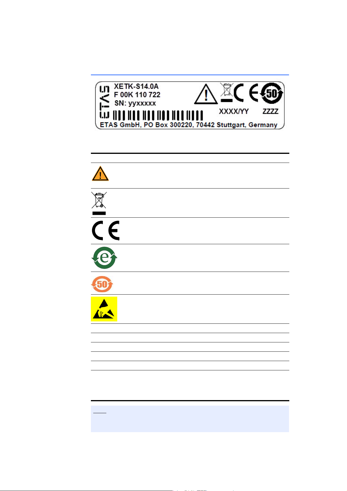
2.4 Identifications on the Product
Fig. 2-1 Adhesive Label (Example: Label for XETK-S14.0)
The following symbols are used for identifications of the product:
Symbol Description
The User's Guide must be read prior to the startup of the
product!
Symbol for WEEE, see chapter 2.5 on page 13
Symbol for CE conformity, see chapter 2.6 on page 13
Symbol for China RoHS, see chapter 2.7.2 on page 13
Symbol for China RoHS, see chapter 2.7.2 on page 13
Symbol for electrostatic sensitive components
XETK-S14.0A Product designation (example)
F 00K 110 722 Order number of the product (example)
SN: yyxxxxx Serial number (7-digit)
XXXX/YY Product version
ZZZZ Year of manufacture
ETAS GmbH,
PO Box 300220,
70442 Stuttgart,
Germany
Manufacturer's address
For symbols and product information one or several adhesive labels can be
used.
XETK-S21.0B - User’s Guide12

ETAS Basic Safety Notices
2.5 Taking the Product Back and Recycling
The European Union has passed a directive called Waste Electrical and Electronic
Equipment, or WEEE for short, to ensure that systems are setup throughout the
EU for the collection, treating and recycling of electronic waste.
This ensures that the devices are recycled in a resource-saving way representing
no danger to health or the environment.
Fig. 2-2 WEEE-Symbol
The WEEE symbol (see Fig. 2-2 on page 13) on the product or its packaging
shows that the product must not be disposed of as residual garbage.
The user is obliged to collect the old devices separately and return them to the
WEEE take-back system for recycling. The WEEE directive concerns all ETAS
devices but not external cables or batteries.
For more information on the ETAS GmbH Recycling software, contact the ETAS
sales and service locations.
2.6 CE marking
With the CE mark attached to the product or its packaging, ETAS confirms that
the product corresponds to the applicable product-specific European Directives.
The CE Declaration of Conformity for the product is available upon request.
2.7 RoHS Conformity
2.7.1 European Union
The EU Directive 2011/65/EU limits the use of certain dangerous materials for
electrical and electronic devices (RoHS conformity).
This product does not contain any of the restricted substances specified in the EU
Directive 2011/65/EU or exceeds the maximum concentrations stipulated
therein. For individual electronic components used in our products, there are currently no equivalent alternative substances, which is why we make use of the
exceptions 7A and 7C-I in Annex III of this Directive.
ETAS confirms that the product corresponds to this directive which is applicable
in the European Union.
2.7.2 China
ETAS confirms that the product meets the product-specific applicable guidelines
of the China RoHS (Management Methods for Controlling Pollution Caused by
Electronic Information Products Regulation) applicable in China with the China
RoHS marking affixed to the product or its packaging.
XETK-S21.0B - User’s Guide 13

Basic Safety Notices ETAS
2.8 Declarable Substances
European Union
Some products from ETAS GmbH (e.g. modules, boards, cables) use components
with substances that are subject to declaration in accordance with the REACH
regulation (EU) no.1907/2006.
Detailed information is located in the ETAS download center in the customer
information "REACH Declaration" (www.etas.com/Reach
continuously being updated.
). This information is
2.9 Use of Open Source Software
The product uses Open Source Software (OSS). This software is installed in the
product at the time of delivery and does not have to be installed or updated by
the user. Reference shall be made to the use of the software in order to fulfill
OSS licensing terms. Additional information is available in the document "OSS
Attributions List" at the ETAS website www.etas.com
.
XETK-S21.0B - User’s Guide14
ETAS Introduction
Note
Note
3 Introduction
This section contains information about the basic features and applications of
the XETK-S21.0 Interface Board (ETK = Emulator Test Probe), hints to system
requirements for operating the XETK-S21.0, and other details.
3.1 Applications
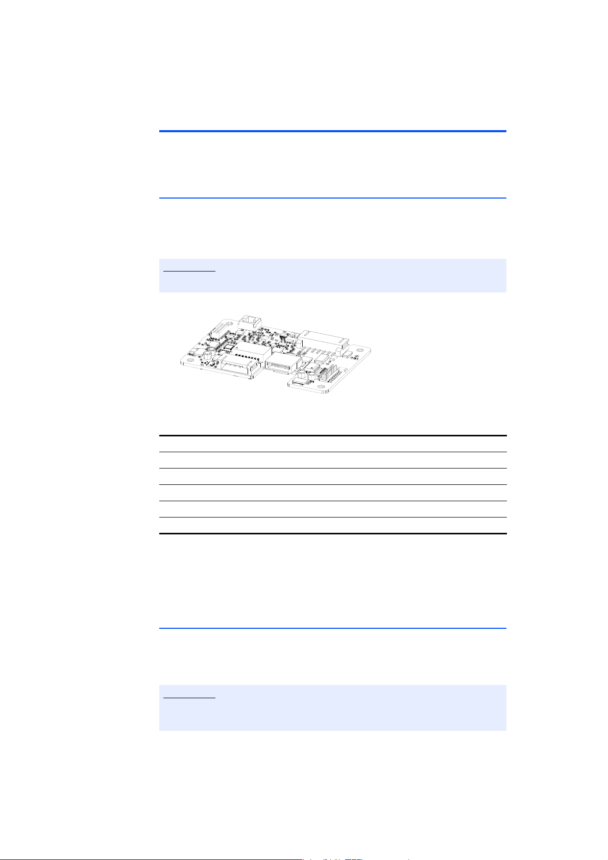
The XETK-S21.0 is an emulator probe for the Freescale MPC57xx and for the
STMicroelectronics EM57xx microcontroller family. It is a typical serial XETK
designed for use with the JTAG portion of the Nexus debug interface (IEEE/ISTO
5001).
For supported MPC57xx microcontrollers, refer to chapter 7.1.3 on page 35.
Fig. 3-1 XETK-S21.0
XETK ECU interface connectors 12 pin ERNI plus 7 pin JST
Power supply for ED devices (VDDSBRAM) min. 1.25 V
SBRAM sense Yes, on board or external sense
Pinless triggering Yes
Timer triggering Yes
The XETK-S21.0 supports the standard full duplex 100Base-T Ethernet interface
and can be connected directly or via ES51x/ES59x/ES600 modules to the PC. No
additional ETAS modules are required for the access to the ECU. The XETK-S21.0
can be used for rapid prototyping applications (bypass) as well as for measurement and calibration applications.
3.2 Features
• Measurement interface:
– 3.3 V JTAG output levels, 5.0 V tolerant JTAG input
– Configurable JTAG interface clock speed: 20 MHz, 40 MHz, 50 MHz
XETK-S21.0
The max. allowed JTAG clock depends on the core frequency of the microcontroller. Max. clock speed is typically 1/4 of the core frequency.
XETK-S21.0B - User’s Guide 15

Introduction ETAS
– Pinless startup protocol for XETK recognition and data acquisition trig-
gering
• Calibration:
– Microcontroller capability of internal Flash emulation can be used
– XETK powers Emulation Device RAM (for calibration purpose)
– Supports “Start on Any Page”
• Debugger interface:
– XETK provides additional connector for external debug hardware
– simultaneously use XETK and debugger
• Supports special coldstart mechanism (“Calibration Wake Up”):
– Calibration Wake Up: Wake up mechanism to wake up the power sup-
ply of the ECU via the Calibration Wake up pin
– Pull CalWakeUp until Startup Handshake: duration of the Wake up
mechanism is configurable
• ECU flashing via XETK
– Braindead flashing under ProF control
• Permanent storage of configuration in EEPROM
• Fast Ethernet Interface:
– Direct connection to PC
– Open XCP on Ethernet Protocol
– Supports a variety of standard applications
• “ETK Drivers and Tools” update to support ETAS software tools (INCA,
XCT)
• Firmware update (programming of the logic device) through HSP software
service packs; removal of XETK or ECU is not necessary
• Mounting possibilities inside or on top of ECU
• Temperature range suitable for automotive application
For more technical data on the XETK-S21.0 consult the chapter "Technical Data"
on page 35.
XETK-S21.0B - User’s Guide16
ETAS Hardware Description
CALWAKEUP
XCP on
Ethernet
Interface
SRAM
System
Functions
Arbiter
100
MBit/s
Ethernet
Phyte
r
Ethernet
Phy
Automatic
Power On
Ethernet
Traffic
Detection
Ethernet
Traffic
Detection
Power
Supply
Monitoring
ECU
Reset
&
Power
Control
DMA
MCU
Core
Ethernet
MAC
Measurement
& Calibration
Unit
ECU
Access
Unit
Serial Flash
Configuration
&
Manufacturing
Data
Time
Sync.
JTAG Signals
Resets + WD_DIS
Power
Supply
4.3V...36V
Standby
Supply
4.3V...36V
Power
Debugger
Connector
JTA G
Arbitration
Buf f er s
ECU Interface
Connectors
ECU
Buf f er s
ECU
SBRAM
POWER
SUPPLY
7-Pin JST
12-Pin ERNI
JTAG
1.25V
Resets + WD_DIS
U-BATT Input
Debugger Signals
JTAG, WD_DIS, Resets, VCC
Sense
ECU &
SBRAM
Power
Supplies
4 Hardware Description
In this chapter, the function blocks of the XETK-S21.0 are explained in detail.
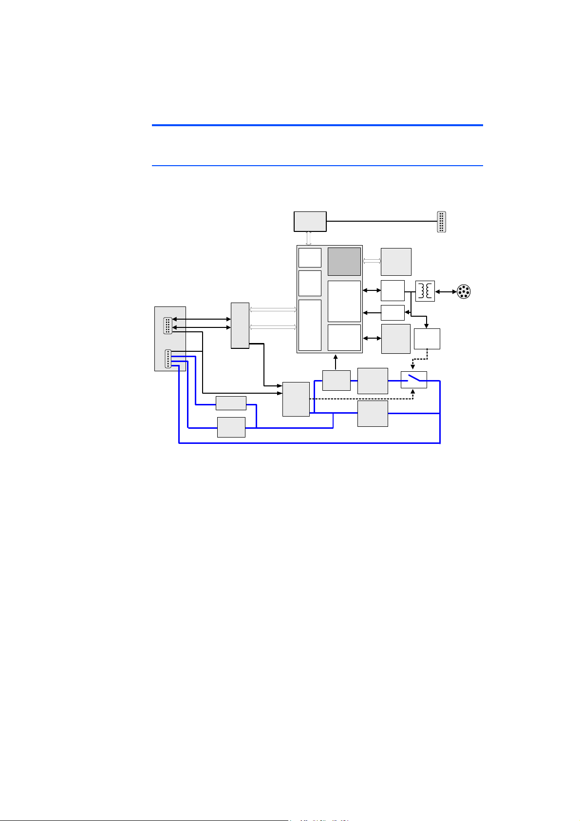
4.1 Architecture
Fig. 4-1 shows the block diagram of the XETK-S21.0.
Fig. 4-1 XETK-S21.0 Architecture
While the microcontroller accesses the program data (not the program code) out
of the data emulation memory provided by the microcontroller, the content of
the data emulation memory can simultaneously be modified by the calibration
and development system through the XETK Ethernet interface. This process
enables adjustments of parameters, characteristic lines and maps through the
calibration and development system. Using an additional measurement data
memory area, the ECU microcontroller can provide data to the calibration and
development system by buffering the data (DISTAB13) and triggering the XETK
to read the data via JTAG. The XETK then reads, buffers, processes and sends this
measured data to the PC.
If no additional measurement data memory is available, the XETK-S21.0 can
alternatively read the data to be measured directly from the microcontroller’s
memory. This process is Triggered Direct Measurement (TDM) with DISTAB13.
The 100 Mbit/s XETK Ethernet interface provides communication with the PC.
The power supply for the XETK-S21.0 is provided by a switch mode power supply, to minimize power dissipation.
XETK-S21.0B - User’s Guide 17
Hardware Description ETAS
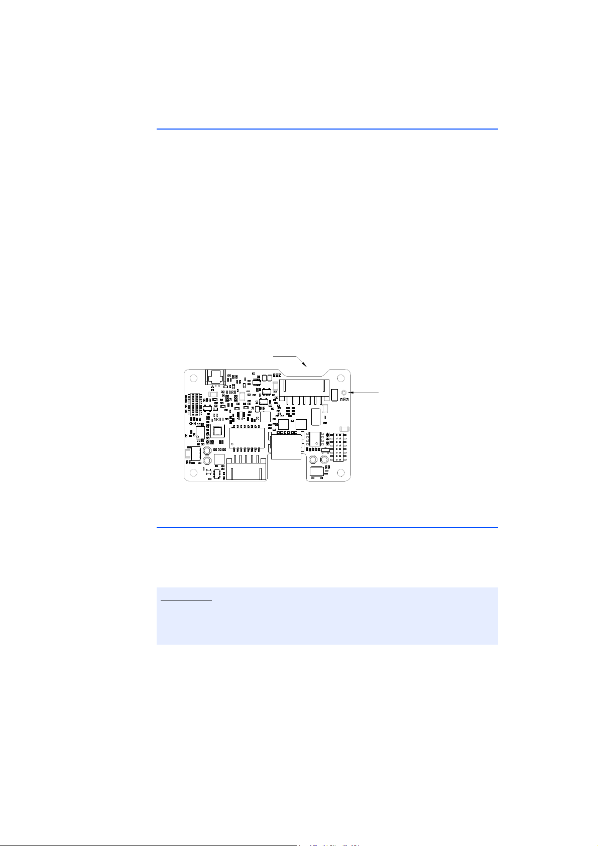
CON6
CON7
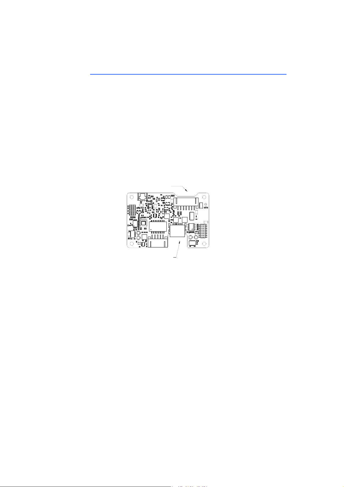
4.2 ECU Interface
The XETK-S21.0 is connected via connectors CON6 and CON7 to the ECU with
two adapter cables (refer to Fig. 4-2 on page 18). The pin definition depends on
the application and the microcontroller type. In general the ECU interface consists of
• 1 ECU voltage line, which is not used for XETK power supply, but only for
detection of the ECU status, therefore the power consumption on this line
is negligible (refer to chapter 4.5 on page 21)
• 1 Reset line which allows the XETK to control the system reset of the ECU
• 1 Reset line which allows the XETK to monitor the system reset of the ECU
• 5 Debug line interfaces for the communication between the XETK-S21.0
and the microcontroller
• 2 ground lines for proper shielding of the ECU interface lines.
Fig. 4-2 Location of the ECU Interfaces
XETK-S21.0B - User’s Guide18
ETAS Hardware Description
Note
Note
CON5
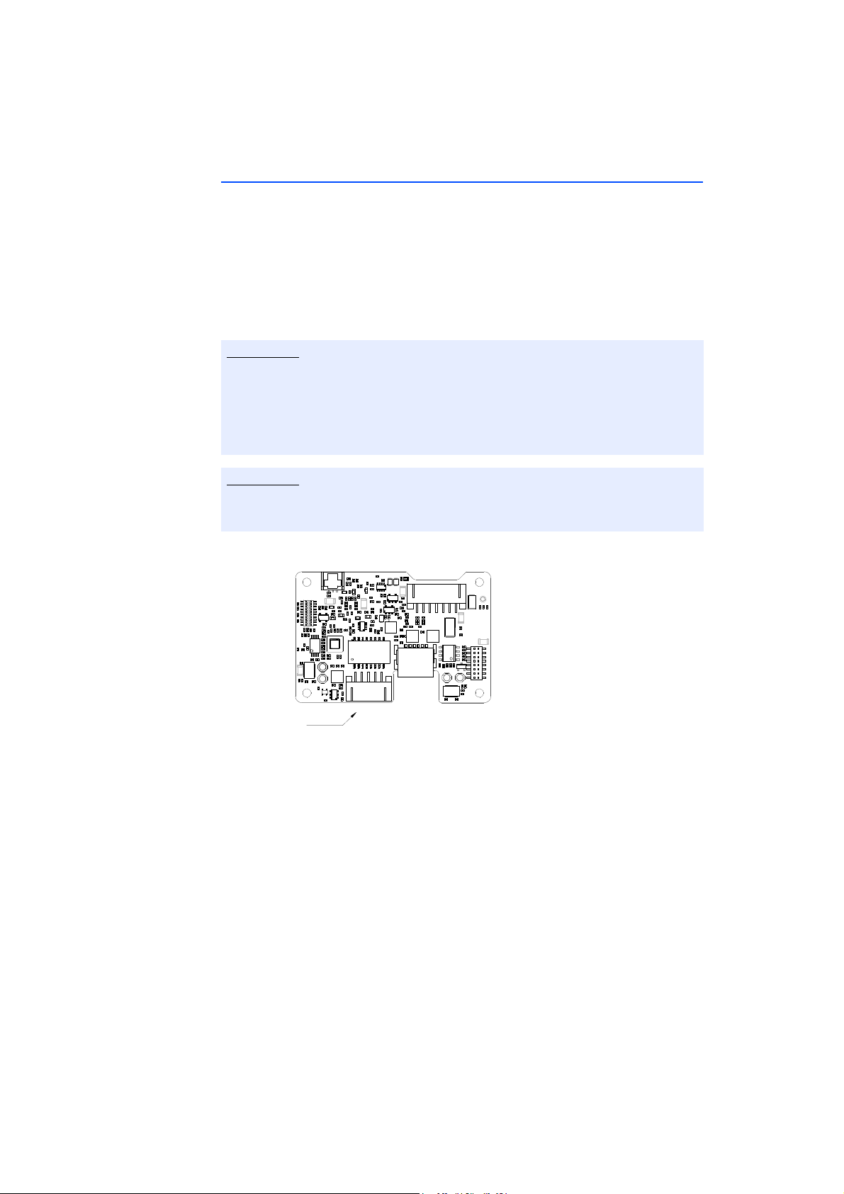
4.3 XETK Ethernet Interface
The XETK Ethernet interface can be directly connected to the PC via CON5 (refer
to Fig. 4-3). No additional ETAS module is required for the access to the ECU.
The interface is a standard full duplex 100Base-TX Ethernet interface using the
XCP protocol. The XETK Ethernet interface is integrated in the ETAS IP world with
automatic IP management and supports the open automotive "Universal Measurement and Calibration" standard "XCP on Ethernet" (TCP/IP, UDP/IP). The
open XCP on Ethernet interface allows for connecting to the
third party application softw
The XETK Ethernet interface is not compatible with the ETK interfaces in modules like e.g. ES910, ES590, ES591, ES592, ES593-D, ES595, ES1232-A. The
XETK Ethernet interface is compatible with the ECU interface of the ES910
module and the Ethernet interfaces of the ES51x/ ES592/ ES593-D/ ES595/
ES600 modules.
are.
XETK-S21.0
with
Please see chapter 7.1.2 on page 35 for additional information regarding PC
requirements for the Ethernet interface.
Fig. 4-3 Location of the XETK Ethernet Interface connector (CON5)
XETK-S21.0B - User’s Guide 19
Hardware Description ETAS
Note
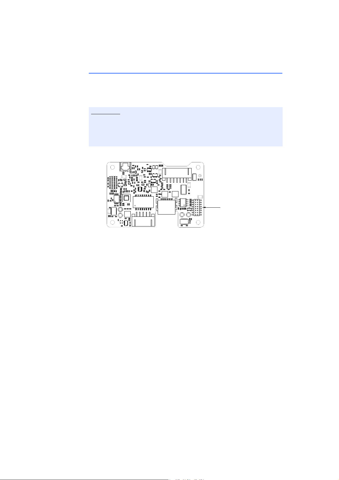
CON1
4.4 Debug Interface
The XETK-S21.0 features a JTAG debugging interface connector CON1 (Samtec
16 pin). This connector can be used to attach debug tool (e.g. Lauterbach or PLS
debugger). It is recommended to use the ETAS Debug - Adapter (e.g. ETAF11 or
AS_ETAF13) to connect the debugger to the XETK.
When using the XETK-S21.0 and ETAF11, the debug tool will not be able to
control the watchdog timer disable pin or monitor the /ESR0 signal provided by
the XETK-S21.0 at CON1. The AS_ETAF13 enables the usage of the watchdog
timer disable pin and /ESR0 signals.
Fig. 4-4 Location of the Debugger Interface (XETK-S21.0)
By using the debug interface at the ECU board for serial ETK connection, it is not
available for debugging tools anymore. Arbitration mechanisms are required to
simultaneously work e.g. with measurement and calibration tools as well as with
debugging tools. The XETK-S21.0 provides a hardware arbitration unit for the
JTAG interface. This enables parallel use of tools for debugging and ETAS tools
for measurement and calibration.
XETK-S21.0B - User’s Guide20
ETAS Hardware Description
Note
CON7
CON4
4.5 Power Supply
The XETK-S21.0 requires a permanent power supply. It is typically powered
directly from the car battery. The input voltage may vary between 4.3 V and
36 V. In case of higher input voltages to the XETK, additional voltage protection
is required. The XETK-S21.0 will also accept voltage dips down to 3V, for a maximum duration of 15ms (for additional details of low voltage operation, see ISO
standard 16750)
From the input battery voltage, the XETK-S21.0 creates all necessary voltages
through switching power supplies on the XETK-S21.0. The power supply of the
ECU is not affected by the XETK-S21.0. An automatic switch ensures that the
power supply of the XETK-S21.0 is automatically switched on and off when the
XETK enters and leaves its standby (sleep) mode.
The XETK-S21.0 can be supplied with power through the seven pin connector,
CON7. The through-hole solder pad CON4 can be used additionally to connect a
power supply U
The power supply on CON4 must use the GND of CON7 pin 3.
Batt2
.
Fig. 4-5 Location of the XETK-S21.0 Power Supply Connectors
4.6 ECU Voltage Supervisor
The ECU voltage (VDDP) is monitored by the XETK to recognize whether the ECU
is switched on or off. Additionally the ECU RAM standby voltage (VDDSBRAM) is
monitored to determine if the standby RAM content is still valid. These two signals are only used for monitoring therefore the load current is negligible.
The XETK-S21.0 only allows switching between reference page and working
page if there is a valid voltage at the sense pin and the working page has been
initialized by the calibration and development system.
The XETK-S21.0 provides two opportunities to supply and supervise the ECU
RAM standby voltage:
1. The XETK-S21.0 monitors the VDDSBRAM supply on board the XETK. The
microcontroller’s standby power supply pin must be connected to the
XETK pin VDDSBRAM.
XETK-S21.0B - User’s Guide 21
 Loading...