

ETAS ES511.1 User Manual

ES511.1
CAN and LIN Network Module
User’s Guide

Copyright
The data in this document may not be altered or amended without special
notification from ETAS GmbH. ETAS GmbH undertakes no further obligation in
relation to this document. The software described in it can only be used if the
customer is in possession of a general license agreement or single license.
Using and copying is only allowed in concurrence with the specifications
stipulated in the contract.
Under no circumstances may any part of this document be copied, reproduced, transmitted, stored in a retrieval system or translated into another
language without the express written permission of ETAS GmbH.
© Copyright 2009 ETAS GmbH, Stuttgart
The names and designations used in this document are trademarks or brands
belonging to the respective owners.
TTN F 00K 106 585 R1.0.1 EN
2

Contents
1 General Information . . . . . . . . . . . . . . . . . . . . . . . . . . . . . . . . . . . . . . . . . . . . . . . 7
1.1 Basic Safety Instructions . . . . . . . . . . . . . . . . . . . . . . . . . . . . . . . . . . . . . . 7
1.1.1 Product Liability Disclaimer (ETAS Disclaimer) . . . . . . . . . . . . . . . 7
1.1.2 Correct Use . . . . . . . . . . . . . . . . . . . . . . . . . . . . . . . . . . . . . . . . 9
1.1.3 Labeling of Safety Instructions . . . . . . . . . . . . . . . . . . . . . . . . . . 9
1.1.4 Demands made re the Technical State of the Product . . . . . . . . . 9
1.2 Taking the Product Back and Recycling . . . . . . . . . . . . . . . . . . . . . . . . . . 10
1.3 About This Manual . . . . . . . . . . . . . . . . . . . . . . . . . . . . . . . . . . . . . . . . . 11
1.3.1 Structure . . . . . . . . . . . . . . . . . . . . . . . . . . . . . . . . . . . . . . . . . 11
1.3.2 Using this Manual. . . . . . . . . . . . . . . . . . . . . . . . . . . . . . . . . . . 12
1.4 Package Contents . . . . . . . . . . . . . . . . . . . . . . . . . . . . . . . . . . . . . . . . . . 13
2 Hardware Description . . . . . . . . . . . . . . . . . . . . . . . . . . . . . . . . . . . . . . . . . . . . . 15
2.1 Modules of the ES51x Line . . . . . . . . . . . . . . . . . . . . . . . . . . . . . . . . . . . 15
2.2 ES511.1 Features . . . . . . . . . . . . . . . . . . . . . . . . . . . . . . . . . . . . . . . . . . . 15
2.3 Housing . . . . . . . . . . . . . . . . . . . . . . . . . . . . . . . . . . . . . . . . . . . . . . . . . 17
2.4 Serial Number . . . . . . . . . . . . . . . . . . . . . . . . . . . . . . . . . . . . . . . . . . . . . 17
2.5 Ports . . . . . . . . . . . . . . . . . . . . . . . . . . . . . . . . . . . . . . . . . . . . . . . . . . . . 17
2.5.1 Front Panel. . . . . . . . . . . . . . . . . . . . . . . . . . . . . . . . . . . . . . . . 17
2.5.2 Back Panel . . . . . . . . . . . . . . . . . . . . . . . . . . . . . . . . . . . . . . . . 18
Contents 3

2.6 LEDs . . . . . . . . . . . . . . . . . . . . . . . . . . . . . . . . . . . . . . . . . . . . . . . . . . . . 18
2.6.1 Overview . . . . . . . . . . . . . . . . . . . . . . . . . . . . . . . . . . . . . . . . . 18
2.6.2 LED Display. . . . . . . . . . . . . . . . . . . . . . . . . . . . . . . . . . . . . . . . 19
3 Functional Description . . . . . . . . . . . . . . . . . . . . . . . . . . . . . . . . . . . . . . . . . . . . 21
3.1 Block Diagram . . . . . . . . . . . . . . . . . . . . . . . . . . . . . . . . . . . . . . . . . . . . . 21
3.2 Power Supply (6-32V DC) . . . . . . . . . . . . . . . . . . . . . . . . . . . . . . . . . . . . 21
3.3 Ethernet Switch . . . . . . . . . . . . . . . . . . . . . . . . . . . . . . . . . . . . . . . . . . . . 21
3.3.1 “HOST” Port . . . . . . . . . . . . . . . . . . . . . . . . . . . . . . . . . . . . . . 22
3.3.2 “ETH1”, “ETH2”, “ETH3” Port. . . . . . . . . . . . . . . . . . . . . . . . . 22
3.3.3 Power-Saving Feature . . . . . . . . . . . . . . . . . . . . . . . . . . . . . . . . 23
3.4 CAN Interface ("CAN 1", "CAN 2") . . . . . . . . . . . . . . . . . . . . . . . . . . . . 23
3.4.1 Operating Modes . . . . . . . . . . . . . . . . . . . . . . . . . . . . . . . . . . . 23
3.4.2 Feature. . . . . . . . . . . . . . . . . . . . . . . . . . . . . . . . . . . . . . . . . . . 24
3.4.3 Bus Terminating Resistor . . . . . . . . . . . . . . . . . . . . . . . . . . . . . . 24
3.5 LIN Interface ("LIN 1", "LIN 2") . . . . . . . . . . . . . . . . . . . . . . . . . . . . . . . . 24
3.5.1 Operating Modes . . . . . . . . . . . . . . . . . . . . . . . . . . . . . . . . . . . 24
3.5.2 Feature. . . . . . . . . . . . . . . . . . . . . . . . . . . . . . . . . . . . . . . . . . . 24
3.5.3 Power Supply on the Bus . . . . . . . . . . . . . . . . . . . . . . . . . . . . . 24
3.6 FlexRay Interface ("FLEXRAY A", "FLEXRAY B") . . . . . . . . . . . . . . . . . . . . 25
3.6.1 Feature. . . . . . . . . . . . . . . . . . . . . . . . . . . . . . . . . . . . . . . . . . . 25
3.6.2 Bus Termination Resistor . . . . . . . . . . . . . . . . . . . . . . . . . . . . . . 25
3.7 Module Network . . . . . . . . . . . . . . . . . . . . . . . . . . . . . . . . . . . . . . . . . . . 26
3.8 Time Synchronization . . . . . . . . . . . . . . . . . . . . . . . . . . . . . . . . . . . . . . . 26
3.9 Firmware Update . . . . . . . . . . . . . . . . . . . . . . . . . . . . . . . . . . . . . . . . . . . 27
4 Getting Started. . . . . . . . . . . . . . . . . . . . . . . . . . . . . . . . . . . . . . . . . . . . . . . . . . 29
4.1 Applications . . . . . . . . . . . . . . . . . . . . . . . . . . . . . . . . . . . . . . . . . . . . . . 29
4.1.1 ES511.1 with XETK, ES590 and ES400 Modules . . . . . . . . . . . . 29
4.1.2 ES510.1 with ES511 and ES512 Measure Modules . . . . . . . . . . 30
4.2 Wiring . . . . . . . . . . . . . . . . . . . . . . . . . . . . . . . . . . . . . . . . . . . . . . . . . . . 31
4.2.1 “HOST” Port . . . . . . . . . . . . . . . . . . . . . . . . . . . . . . . . . . . . . . 31
4.2.2 “6-32V” Port . . . . . . . . . . . . . . . . . . . . . . . . . . . . . . . . . . . . . . 31
4.2.3 “ETH1”, “ETH2”, “ETH3” Port. . . . . . . . . . . . . . . . . . . . . . . . . 32
4.3 Configuring the ES511.1 . . . . . . . . . . . . . . . . . . . . . . . . . . . . . . . . . . . . . 34
4.3.1 Web Interface. . . . . . . . . . . . . . . . . . . . . . . . . . . . . . . . . . . . . . 34
4.3.2 Launching the ES511.1 Web Interface . . . . . . . . . . . . . . . . . . . 34
4.3.3 Configuring the “Auto / On Switch” Function . . . . . . . . . . . . . 34
5 Technical Data . . . . . . . . . . . . . . . . . . . . . . . . . . . . . . . . . . . . . . . . . . . . . . . . . . 37
5.1 General Data . . . . . . . . . . . . . . . . . . . . . . . . . . . . . . . . . . . . . . . . . . . . . . 37
Contents4

5.1.1 Fulfilled Standards and Norms . . . . . . . . . . . . . . . . . . . . . . . . . 37
5.1.2 Environmental Conditions . . . . . . . . . . . . . . . . . . . . . . . . . . . . 37
5.1.3 Mechanical Data . . . . . . . . . . . . . . . . . . . . . . . . . . . . . . . . . . . 38
5.2 System Requirements . . . . . . . . . . . . . . . . . . . . . . . . . . . . . . . . . . . . . . . 38
5.2.1 Hardware . . . . . . . . . . . . . . . . . . . . . . . . . . . . . . . . . . . . . . . . . 38
5.2.2 Ethernet Interface of the PC . . . . . . . . . . . . . . . . . . . . . . . . . . . 38
5.2.3 Supported Applications and Software Requirements. . . . . . . . . 38
5.3 Electrical Data . . . . . . . . . . . . . . . . . . . . . . . . . . . . . . . . . . . . . . . . . . . . . 39
5.3.1 Interface „HOST“ . . . . . . . . . . . . . . . . . . . . . . . . . . . . . . . . . . 39
5.3.2 Power Supply . . . . . . . . . . . . . . . . . . . . . . . . . . . . . . . . . . . . . 40
5.3.3 Ethernet Interfaces . . . . . . . . . . . . . . . . . . . . . . . . . . . . . . . . . 40
5.3.4 CAN Interfaces ("CAN 1" and "CAN 2") . . . . . . . . . . . . . . . . . 41
5.3.5 LIN Interfaces ("LIN 1" and "LIN 2") . . . . . . . . . . . . . . . . . . . . 41
5.4 Pin Assignment . . . . . . . . . . . . . . . . . . . . . . . . . . . . . . . . . . . . . . . . . . . 42
5.4.1 Interface „6-32V“ . . . . . . . . . . . . . . . . . . . . . . . . . . . . . . . . . . 42
5.4.2 Interface „HOST“ . . . . . . . . . . . . . . . . . . . . . . . . . . . . . . . . . . 43
5.4.3 Interface „ETH1“ . . . . . . . . . . . . . . . . . . . . . . . . . . . . . . . . . . . 43
5.4.4 Interface „ETH2“ . . . . . . . . . . . . . . . . . . . . . . . . . . . . . . . . . . . 44
5.4.5 Interface „ETH3“ . . . . . . . . . . . . . . . . . . . . . . . . . . . . . . . . . . . 44
5.4.6 Interface „CAN 1“ . . . . . . . . . . . . . . . . . . . . . . . . . . . . . . . . . . 45
5.4.7 Interface „CAN 2“ . . . . . . . . . . . . . . . . . . . . . . . . . . . . . . . . . . 45
5.4.8 Interface „LIN 1“ . . . . . . . . . . . . . . . . . . . . . . . . . . . . . . . . . . . 46
5.4.9 Interface „LIN 2“ . . . . . . . . . . . . . . . . . . . . . . . . . . . . . . . . . . . 46
6 Cable and Accessories . . . . . . . . . . . . . . . . . . . . . . . . . . . . . . . . . . . . . . . . . . . . 47
6.1 Power Supply Cable . . . . . . . . . . . . . . . . . . . . . . . . . . . . . . . . . . . . . . . . 47
6.2 Ethernet Cable . . . . . . . . . . . . . . . . . . . . . . . . . . . . . . . . . . . . . . . . . . . . 48
6.2.1 CBE500-3 Cable. . . . . . . . . . . . . . . . . . . . . . . . . . . . . . . . . . . . 48
6.2.2 CBE530-x Cable . . . . . . . . . . . . . . . . . . . . . . . . . . . . . . . . . . . . 48
6.3 CAN-/ LIN-/ FlexRay Cable . . . . . . . . . . . . . . . . . . . . . . . . . . . . . . . . . . . . 49
6.3.1 CAN Terminating Resistor . . . . . . . . . . . . . . . . . . . . . . . . . . . . . 49
7 Ordering Informationen . . . . . . . . . . . . . . . . . . . . . . . . . . . . . . . . . . . . . . . . . . . 51
7.1 ES511.1 . . . . . . . . . . . . . . . . . . . . . . . . . . . . . . . . . . . . . . . . . . . . . . . . . 51
7.2 Accessoires . . . . . . . . . . . . . . . . . . . . . . . . . . . . . . . . . . . . . . . . . . . . . . . 51
7.2.1 Power Supply Cables . . . . . . . . . . . . . . . . . . . . . . . . . . . . . . . . 51
7.2.2 Ethernet Cables . . . . . . . . . . . . . . . . . . . . . . . . . . . . . . . . . . . . 51
7.2.3 CAN-/ LIN-/ FlexRay Cable . . . . . . . . . . . . . . . . . . . . . . . . . . . . 51
7.2.4 CAN Termination Resistor . . . . . . . . . . . . . . . . . . . . . . . . . . . . 52
Contents 5

8 Appendix: Troubleshooting Problems . . . . . . . . . . . . . . . . . . . . . . . . . . . . . . . . . 53
8.1 Error LEDs . . . . . . . . . . . . . . . . . . . . . . . . . . . . . . . . . . . . . . . . . . . . . . . . 53
8.2 Troubleshooting ES511.1 Problems . . . . . . . . . . . . . . . . . . . . . . . . . . . . . 53
8.3 Problems and Solutions . . . . . . . . . . . . . . . . . . . . . . . . . . . . . . . . . . . . . . 54
8.3.1 Network Adapter cannot be selected via Network Manager . . . 54
8.3.2 Search for Ethernet Hardware fails . . . . . . . . . . . . . . . . . . . . . . 55
8.3.3 Personal Firewall blocks Communication. . . . . . . . . . . . . . . . . . 57
9 ETAS Contact Addresses . . . . . . . . . . . . . . . . . . . . . . . . . . . . . . . . . . . . . . . . . . . 63
List of Figures . . . . . . . . . . . . . . . . . . . . . . . . . . . . . . . . . . . . . . . . . . . . . . . . . . . 65
Index . . . . . . . . . . . . . . . . . . . . . . . . . . . . . . . . . . . . . . . . . . . . . . . . . . . . . . . . . 67
Contents6
1 General Information
The introductory chapter provides you with information on the basic safety
instructions, returning the product and recycling, how to use this manual, the
delivery scope and other details.
1.1 Basic Safety Instructions
Please adhere to the following safety instructions to avoid injury to yourself
and others as well as damage to the device.
1.1.1 Product Liability Disclaimer (ETAS Disclaimer)
WARNING!
The use and application of this product can be dangerous. It is
critical that you carefully read and follow the instructions and
warnings below and in the associated user manuals.
This ETAS product enables a user to influence or control the electronic systems
in a vehicle or in a testbench. THE PRODUCT IS SPECIFICALLY DESIGNED FOR
THE EXCLUSIVE USE BY PERSONNEL WHO HAVE SPECIAL EXPERIENCE AND
TRAINING.
Improper use or unskilled application of this ETAS product may alter the vehicle
performance or system performance in a manner that results in death, serious
personal injury or property damage.
• Do not use this ETAS product if you do not have the proper
experience and training.
• Also, if a product issue develops, ETAS will prepare a Known
Issue Report (KIR) and post it on the internet. The report
includes information regarding the technical impact and status
of the solution. Therefore you must check the KIR applicable to
this ETAS product version and follow the relevant instructions
prior to operation of the product.
The Known Issue Report (KIR) can be found here:
http://www.etasgroup.com/kir
• Any data acquired through the use of this ETAS product must be
verified for reliability, quality and accuracy prior to use or distribution. This applies both to calibration data and to measurements that are used as a basis for calibration work.
General Information 7

• When using this ETAS product with vehicle systems that influence vehicle behavior and can affect the safe operation of the
vehicle, you must ensure that the vehicle can be transitioned to
a safe condition if a malfunction or hazardous incident should
occur.
• When using this ETAS product with test-bench systems that
influence system behavior and can affect the safe operation of
the system, you must ensure that the test-bench can be transitioned to a safe condition if a malfunction or hazardous incident
should occur.
• All legal requirements, including regulations and statutes
regarding motor vehicles and test-benches, must be strictly followed when using this product.
• It is recommended that in-vehicle use of the ETAS product be
conducted on enclosed test tracks.
• Use of this ETAS product on a public road should not occur
unless the specific calibration and settings have been preciously
tested and verified as safe.
IF YOU FAIL TO FOLLOW THESE INSTRUCTIONS, THERE MIGHT BE A
RISK OF DEATH, SERIOUS INJURY OR PROPERTY DAMAGE.
THE ETAS GROUP OF COMPANIES AND THEIR REPRESENTATIVES, AGENTS
AND AFFILIATED COMPANIES DENY ANY LIABILITY FOR THE FUNCTIONAL
IMPAIRMENT OF ETAS PRODUCTS IN TERMS OF FITNESS, PERFORMANCE AND
SAFETY IF NON-ETAS SOFTWARE OR MODEL COMPONENTS ARE USED WITH
ETAS PRODUCTS OR DEPLOYED TO ACCESS ETAS PRODUCTS. ETAS PROVIDES NO WARRANTY OF MERCHANTABILITY OR FITNESS OF THE ETAS
PRODUCTS IF NON-ETAS SOFTWARE OR MODEL COMPONENTS ARE USED
WITH ETAS PRODUCTS OR DEPLOYED TO ACCESS ETAS PRODUCTS.
THE ETAS GROUP OF COMPANIES AND THEIR REPRESENTATIVES, AGENTS
AND AFFILIATED COMPANIES SHALL NOT BE LIABLE FOR ANY DAMAGE OR
INJURY CAUSED BY IMPROPER USE OF THIS PRODUCT. ETAS PROVIDES
TRAINING REGARDING THE PROPER USE OF THIS PRODUCT.
If you cannot agree with these limitations, you may return this product free of
charge within a (1) month after receipt. You will immediately be refunded the
full purchase price. A return is not possible in case of developments, modifications or services ordered by customer.
General Information8
1.1.2 Correct Use
ETAS GmbH cannot be made liable for damage which is caused by incorrect
use and not adhering to the safety instructions.
1.1.3 Labeling of Safety Instructions
The safety instructions contained in this manual are shown with the standard
danger symbol shown below:
The following safety instructions are used. They provide extremely important
information. Please read this information carefully.
WARNING!
Indicates a possible medium-risk danger which could lead to serious or even fatal injuries if not avoided.
CAUTION!
Indicates a low-risk danger which could result in minor or less serious injury or damage if not avoided.
1.1.4 Demands made re the Technical State of the Product
The following requirements are made to ensure safe operation of the module:
• Ensure you observe the notes on environmental conditions (see section
5.1.2 on page 37).
• Ensure you adhere to the port and setting values (see section 5.3.1
on page 39 and section 5.3.2 on page 40).
CAUTION!
The module can be damaged or destroyed!
Do not open or change the module!
Work on the module must only be carried out by specialist, qualified personnel.
General Information 9

1.2 Taking the Product Back and Recycling
The European Union has passed a directive called Waste Electrical and Electronic Equipment, or WEEE for short, to ensure that systems are setup throughout the EU for the collection, treating and recycling of electronic waste.
This ensures that the devices are recycled in a resource-saving way representing
no danger to health or the environment.
Fig. 1-1 WEEE Symbol
The WEEE symbol (see Fig. 1-1 on page 10) on the product or its packaging
shows that the product must not be disposed of as residual garbage.
The user is obliged to collect the old devices separately and return them to the
WEEE take-back system for recycling.
The WEEE directive concerns all ETAS devices but not external cables or batteries.
For more information on the ETAS GmbH Recycling Program, contact the ETAS
sales and service locations (see chapter 9 on page 63).
General Information10

1.3 About This Manual
This manual describes the startup and technical data of the ES511.1 module.
1.3.1 Structure
This manual consists of eight chapters and an index.
• Chapter 1: “Introduction”
The “Introduction” (this chapter) provides you with information on the
basic safety instructions, returning the product and recycling, how to
use this manual, the delivery scope and other details.
• Chapter 2: “Hardware Description”
The “Hardware Description” chapter provides you with an overview of
the ES511.1 with information on the housing, serial number, ports and
LEDs.
• Chapter 3: “Functional Description”
The “Functional Description” chapter describes the block diagram,
power supply, Ethernet switch, module network, time synchronization
and the firmware update.
• Chapter 4: “Getting Started”
The “Getting Started” chapter includes application examples and notes
on the wiring of the ES511.1.
• Chapter 5: “Technical Data”
The “Technical Data” chapter contains a summary of all technical data
and the pin assignments of the ES511.1 module.
• Chapter 6: “Cables and Accessories”
The “Cables and Accessories” chapter contains an overview of the
available cables and accessories.
• Chapter 7: “Ordering Information”
The “Ordering Information” chapter contains the ordering information
on the available cables and accessories.
• Chapter 8: Appendix A: "Troubleshooting Problems"
This chapter gives some information of what you can do when problems arise with the ES511.1 and problems that are not specific to an
individual software or hardware product.
The final chapter, “ETAS Contacts”, gives you information on ETAS’ international sales and service locations.
General Information 11

1.3.2 Using this Manual
Representation of Information
All activities to be executed by the user are presented in what is referred to as
a “Use-Case” format. I.e. the aim is defined in brief as a title and the relevant
steps necessary to achieve this aim are then listed. The information is displayed
as follows:
Target definition:
Any introductory information...
Any concluding remarks...
Typographic Conventions
The following typographic conventions are used:
Select File → Open. Menu functions are shown in boldface/
Click OK. Buttons are shown in boldface.
Press <E
NTER>. Keyboard commands are shown in
The “Open File” dialog box
appears.
Bold Device labels
Italics Crucial text
•Step 1
Possibly an explanation of step 1...
•Step 2
Possibly an explanation of step 2...
•Step 3
Possibly an explanation of step 3...
blue.
angled
brackets in block capitals.
Names of program windows, dialog
boxes, fields etc. are shown in quotation
marks.
Important notes for the user are shown as follows:
Note
Important note for the user.
General Information12

1.4 Package Contents
Before using your ES511.1, check that the unit has been delivered with all
required parts and cables (see chapter 7.1 on page 51).
Additional cables and adapters can be ordered separately from ETAS. A list of
available accessories and ordering information can be found in the chapter 7.2
on page 51 of this manual or in the ETAS product catalog.
General Information 13

General Information14

2 Hardware Description
This chapter provides you with an overview of the ES511.1 with information
on the housing, serial number, ports and LEDs.
2.1 Modules of the ES51x Line
The ES51x line is a range of powerful measurement and interface modules. All
modules and the relevant cables are intended for use in the lab, on the test
bench and in the passenger cell of vehicles.
The ES511.1 module has an upstream Ethernet interface that guarantees data
exchange with the host PC. The ES51x modules have three downstream Ethernet interfaces that can be connected with ES51x, ES600, measurement and
interface modules.
Fig. 2-1 ES511.1 View of the Device
Individual measurement, calibration and rapid prototyping modules are easy to
combine with ES51x line modules. ECUs that have an XETK, or ECUs that have
their own Ethernet interface can be connected directly with an ES51x module
and communicate with INCA via Ethernet.
If necessary, systems can be cascaded using ES51x nodes. The Ethernet switch
guarantees the time-synchronous sampling of all measurement channels –
even in sizeable module networks.
2.2 ES511.1 Features
Overview of the major features of the ES511.1:
Hardware Description 15

Ethernet switch with a 10/100 MBit/s data rate:
• One host port (upstream)
• Three ports for compatible modules (downstream)
• Can be cascaded up to 15 modules
• Status display for every port
• Automatic standby function
• Precise synchronization of all connected modules and their measurement channels
Two independent CAN interfaces:
• CAN High Speed (max. 1 MBaud)
• Transceiver (Physical layer): Philips TJA1040
• CAN IP Controller
• CAN protocols
– CAN V2.0a (Standard Identifier with 11-bit)
– CAN V2.0b (Extended Identifier with 29-bit)
• Baud rate can be configured by software
Two independent LIN interfaces:
• LIN specification LIN V2.1
• Operating mode Slave (monitoring)
• Transceiver (Physical layer): MCZ33661EF
Additional features of the module:
• Module suitable for use in automotive applications; suitable for use in
the development environment and in the vehicle on test drives.
– Channels galvanically isolated from each other, from the device
ground and from the supply voltage
– Not sensitive to environmental conditions (temperature, EMC)
– Wide supply voltage range
– High mechanical stability and durability
• Part of the ETAS Tool Suite
For the complete technical data of the ES511.1, refer to the chapter "Technical
Data" on page 37.
Hardware Description16
2.3 Housing
Housing with ports on the front and rear of the device is used for the ES511.1.
The sturdy metal housing has nonskid plastic feet and is intended for use in the
lab, on the test bench and in the passenger cell of vehicles.
2.4 Serial Number
The module’s serial number can be found on the front panel of the device.
2.5 Ports
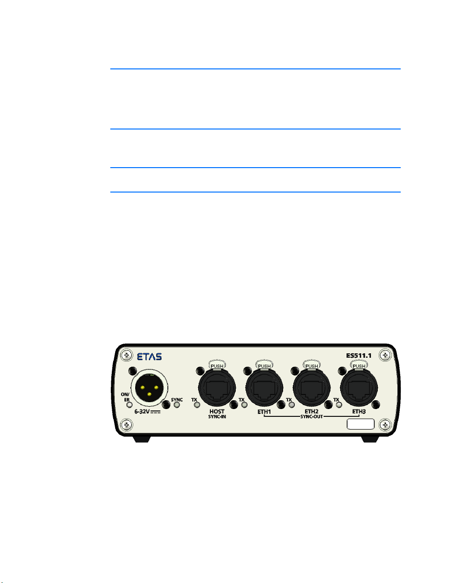
2.5.1 Front Panel
The ES511.1 has an Ethernet port (upstream) to the host PC or to superordinate ES51x modules, three Ethernet ports (downstream) for further ES510.1
and/or measurement and interface modules and a power supply port. RJ-45compatible Neutrik ports are used at the Ethernet ports.
The following ports are on the front of the ES511.1:
• 6-32V (operating voltage)
• HOST (Ethernet, SYNC-IN)
• ETH1 (Ethernet, SYNC-OUT)
• ETH2 (Ethernet, SYNC-OUT)
• ETH3 (Ethernet, SYNC-OUT)
Fig. 2-2 Ports and LEDs
Hardware Description 17
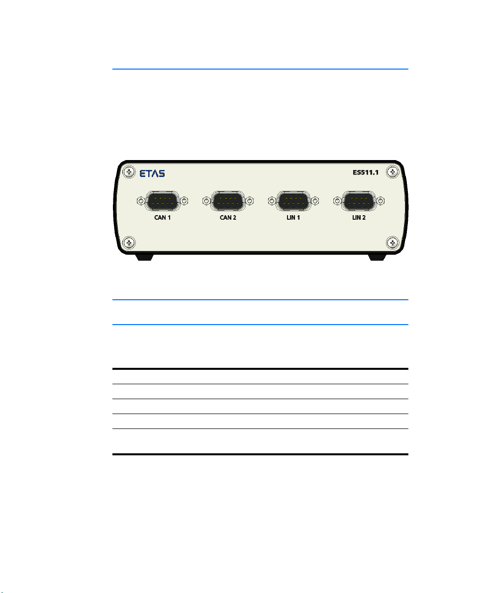
2.5.2 Back Panel
The following ports are on the back of the ES511.1:
• CAN 1 (1 x CAN)
• CAN 2 (1 x CAN)
• LIN 1 (1 x LIN)
• LIN 2 (1 x LIN)
Fig. 2-3 Ports
2.6 LEDs
2.6.1 Overview
The ES511.1 has six LEDs, which indicate the operational, error and synchronization state of the module, as well as with LEDs which display the functional
state of the assigned Ethernet interface.
LED Display
ON/ER Operational state and possible error states of the module
SYNC Synchronization state of the module
TX Function of the HOST interface
TX Function of the assigned ETHx interface
(one LED each for ETH1, ETH2, ETH3)
Hardware Description18

2.6.2 LED Display
What the ON/ER LED Indicates
The module is assigned an ON/ER LED (see Fig. 2-2 on page 17).
LED Display Operational State
ON/ER Red Module is currently booting or booting
What the SYNC LED Indicates
The module is assigned a SYNC LED (see Fig. 2-2 on page 17). The LED indicates the synchronization function of the module (master or slave) and the
synchronization state.
LED Display Operational State
SYNC Blue, flashing,
was unsuccessful.
Red, flashing,
500 ms on/
500 ms off
Green, flashing,
100 ms on/
900 ms off
Green Operational state: On
Off No power supply
fully bright
Blue, flashing
lsemi and fully
bright alternately
Firmware update in progress
Operational state: Standby
The module is a synchronization master;
the module is not synchronized externally
The module is a synchronization slave;
the module is synchronized externally at
the HOST port
What the TX LED Indicates
Each Ethernet port is assigned a TX LED (see Fig. 2-2 on page 17).
LED Display Operational State
TX Yellow Ethernet connection is activated
Yellow, flashing Ethernet data transfer
Off No Ethernet signal
Hardware Description 19

Hardware Description20
3 Functional Description
This chapter describes the block diagram, power supply, Ethernet switch, module network, time synchronization and the firmware update.
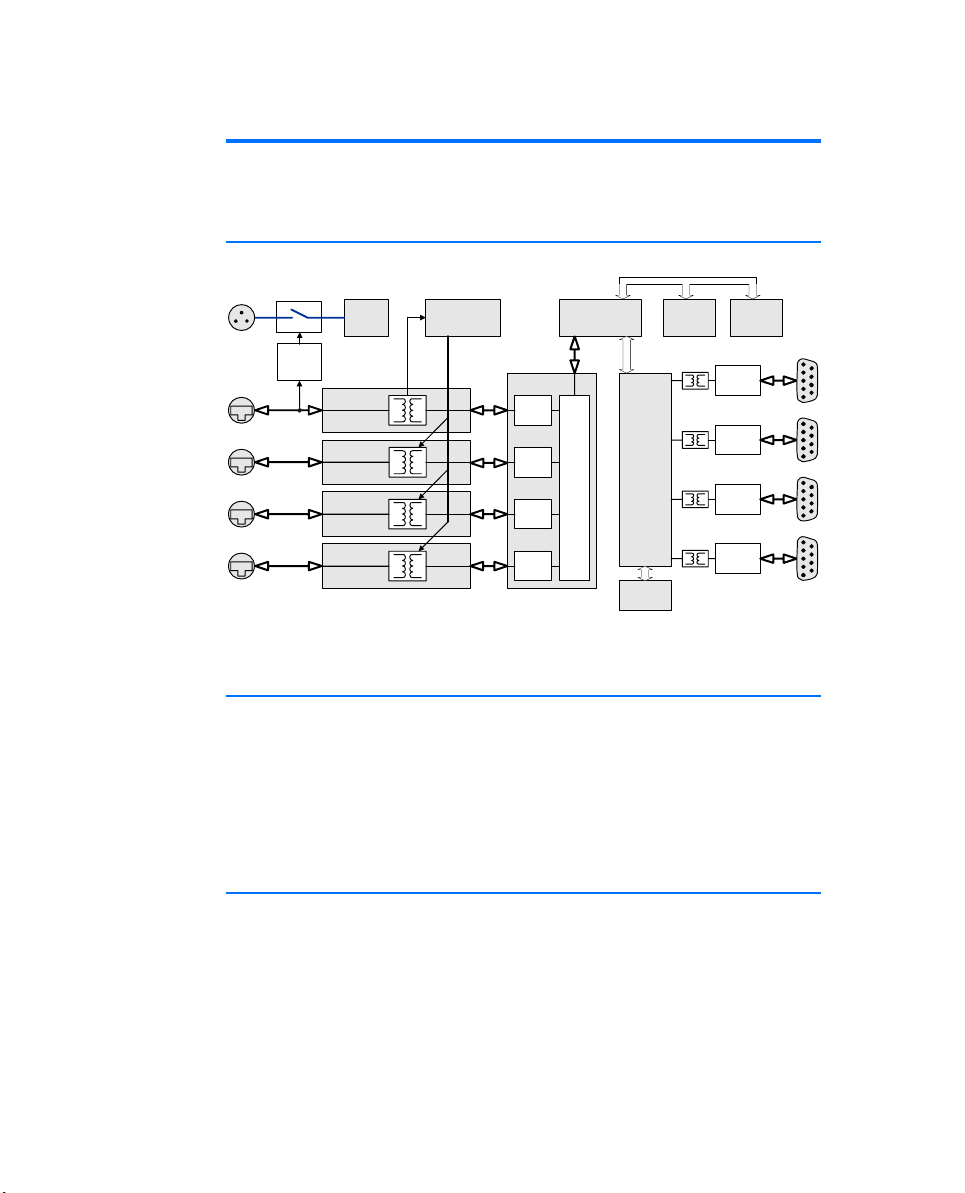
3.1 Block Diagram
Power
6 - 32V
HOST
ETH 1
ETH 2
ETH 3
Ethernet
Traffic
Detection
6 - 32V
Ethernet
Interface
10Base-T
100Base-TX
Ethernet
Interface
10Base-T
100Base-TX
Ethernet
Interface
10Base-T
100Base-TX
Ethernet
Interface
10Base-T
100Base-TX
Supply
Synchronization Unit
Sync IN
Fig. 3-1 Block Diagram
3.2 Power Supply (6-32V DC)
The power supply interface (6-32V DC) is routed to a 3-pin connector (XLR
socket) on the front of the device. An external power supply or the vehicle
battery power the module.
When the ES511.1 is connected to the operating voltage and there is an Ethernet connection at HOST, the module boots. If there is no Ethernet connection, the module changes to “Standby.”
3.3 Ethernet Switch
Time
Sync OUT
Ethernet Switch
Ethernet
Phy
Ethernet
Phy
Ethernet
Phy
Ethernet
Phy
controller
Switch Unit
Micro-
FPGA
(CAN/LIN
Controller)
Synch.
RAM
DDR2
RAM
CAN
Transceiver
CAN
Transceiver
LIN
Transceiver
LIN
Transceiver
Flash
CAN1
CAN2
LIN1
LIN2
The integrated Ethernet switch is used for the connection of the ES511.1 module and other measurement or interface modules to a user PC. Data from the
connected modules of the ES51x line is acquired synchronously (ETAS device
Functional Description 21
 Loading...