

ETAS ES4455.1 User Manual

ES4455.1 Load Board
User’s Guide

Copyright
The data in this document may not be altered or amended without special
notification from ETAS GmbH. ETAS GmbH undertakes no further obligation in
relation to this document. The software described in it can only be used if the
customer is in possession of a general license agreement or single license.
Using and copying is only allowed in concurrence with the specifications
stipulated in the contract.
Under no circumstances may any part of this document be copied, reproduced, transmitted, stored in a retrieval system or translated into another
language without the express written permission of ETAS GmbH.
© Copyright 2008
The names and designations used in this document are trademarks or brands
belonging to the respective owners.
R1.0.1 EN - 09.2008 TTN F 00K 106 170
2
ETAS GmbH, Stuttgart

Contents
1 Introduction . . . . . . . . . . . . . . . . . . . . . . . . . . . . . . . . . . . . . . . . . . . . . . . . . . . . . 5
1.1 Applications . . . . . . . . . . . . . . . . . . . . . . . . . . . . . . . . . . . . . . . . . . . . . . . 6
1.2 Features . . . . . . . . . . . . . . . . . . . . . . . . . . . . . . . . . . . . . . . . . . . . . . . . . . 6
1.3 Load Modules . . . . . . . . . . . . . . . . . . . . . . . . . . . . . . . . . . . . . . . . . . . . . . 8
1.4 Taking the Product Back and Recycling . . . . . . . . . . . . . . . . . . . . . . . . . . . 9
2 Hardware . . . . . . . . . . . . . . . . . . . . . . . . . . . . . . . . . . . . . . . . . . . . . . . . . . . . . . 11
2.1 Numbering the Loads on an ES4455.1 Load Board . . . . . . . . . . . . . . . . . 11
2.1.1 Load Signals to the Backplane . . . . . . . . . . . . . . . . . . . . . . . . . 12
2.1.2 Connecting Loads and Measuring the Signals. . . . . . . . . . . . . . 12
2.2 Current Transducers . . . . . . . . . . . . . . . . . . . . . . . . . . . . . . . . . . . . . . . . 13
2.2.1 Configuring the Current Transducers . . . . . . . . . . . . . . . . . . . . 13
2.2.2 Calibration . . . . . . . . . . . . . . . . . . . . . . . . . . . . . . . . . . . . . . . . 15
2.2.3 Overcurrent Protection of the Measure Outputs . . . . . . . . . . . . 15
2.3 Digital Current Signals . . . . . . . . . . . . . . . . . . . . . . . . . . . . . . . . . . . . . . . 15
2.3.1 Configuring Current Measuring . . . . . . . . . . . . . . . . . . . . . . . . 16
2.3.2 LED Display. . . . . . . . . . . . . . . . . . . . . . . . . . . . . . . . . . . . . . . . 16
2.3.3 Acoustic Signals . . . . . . . . . . . . . . . . . . . . . . . . . . . . . . . . . . . . 16
2.4 Settings in LABCAR-RTC . . . . . . . . . . . . . . . . . . . . . . . . . . . . . . . . . . . . . 17
Contents 3

3 Pin Assignment and Display Elements . . . . . . . . . . . . . . . . . . . . . . . . . . . . . . . . . 19
3.1 “Threshold Calibration Connection” Connector . . . . . . . . . . . . . . . . . . . 19
3.2 LEDs for Status Display . . . . . . . . . . . . . . . . . . . . . . . . . . . . . . . . . . . . . . 20
4 Accessories. . . . . . . . . . . . . . . . . . . . . . . . . . . . . . . . . . . . . . . . . . . . . . . . . . . . . 21
4.1 PB4451CR Piggyback for 2 RB CRS Injectors . . . . . . . . . . . . . . . . . . . . . . 21
4.2 PB4451GDI Piggyback for 2 RB GDI Injectors . . . . . . . . . . . . . . . . . . . . . . 22
5 Technical Data . . . . . . . . . . . . . . . . . . . . . . . . . . . . . . . . . . . . . . . . . . . . . . . . . . 23
6 ETAS Contact Addresses . . . . . . . . . . . . . . . . . . . . . . . . . . . . . . . . . . . . . . . . . . . 25
Index . . . . . . . . . . . . . . . . . . . . . . . . . . . . . . . . . . . . . . . . . . . . . . . . . . . . . . . . . 27
Contents4
1 Introduction
This User’s Guide describes the ES4455.1 Load Board. It consists of the
following chapters:
• "Introduction" on page 5
This chapter – here you will find general information on the ES4455.1
Load Board.
• "Hardware" on page 11
This chapter describes the individual function units of the ES4455.1
Load Board in more detail.
• Pin Assignment and Display Elements
This chapter contains a description of the pins and LEDs on the front
panel of the ES4455.1 Load Board.
• "Accessories" on page 21
This chapter describes the dummy loads available to date which are
assembled as piggybacks on the board of the ES4455.1 Load Board.
• "Technical Data" on page 23
This chapter contains the technical data of the ES4455.1 Load Board.
CAUTION!
Some components of the ES4455.1 Load Board may be damaged
or even destroyed by static discharge. Leave the board in its
transport package until you want to install it.
The ES4455.1 Load Board should only be taken from its package,
configured and installed at a working place that is protected
against static discharge.
WARNING!
The components, connectors and conductors of the ES4455.1
Load Board may carry dangerous voltages. These voltages may
even exist if the ES4455.1 is not installed in the ES4408.1 Load
Chassis or the ES4408.1 Load Chassis is powered off.
Make sure the ES4455.1 is protected against contact during
operation. Disconnect all connectors to the ES4455.1 before
removing the board.
Introduction 5
1.1 Applications
The ES4455.1 Load Board is a carrier board for accommodating two modules
(each with two channels) for simulating high-current loads (to 90 V and to
20 A), such as injection loads.
In the ES4408.1 Load Chassis there are three 14 HP slots for accommodating
ES4455.1 Load Boards or pre-assembled variants (see "“Pre-Assembled
Solutions” with Integrated Load Modules" on page 8).
When fully assembled, the injection loads of a 12-cylinder engine can be
simulated.
1.2 Features
The ES4455.1 Load Board has the following features:
• 3 U plug-in board (14 HP, 3400 mm x 100 mm)
• Four channels for load simulations to 20 A
• Four galvanically isolated analog or digital channels for current
measuring
• Four galvanically isolated analog channels for voltage measuring
• To date, modules for the Bosch Common Rail System (two modules
each with two loads) and Bosch GDI (two modules each with two
loads) are available
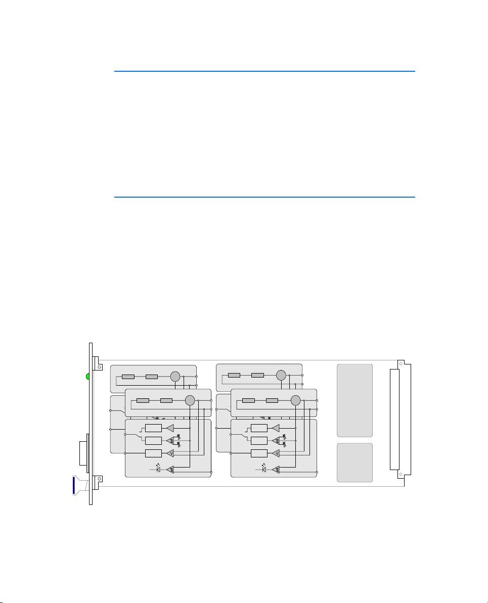
Fig. 1-1 shows the block diagram of the ES4455.1 Load Board.
Load 2
I_Ana_Out
I_Dig_Out
V_Out
Load 3
Protection
Protection
I_Ana_Out
Protection
I_Dig_Out
V_Out
I
Output
Output
Output
Output
Protection
Output
Protection
Output
Protection
Load 1
I
DAC
Load 4
Output
I_Ana_Out
Protection
Output
I_Dig_Out
Protection
V_Out
Output
I_Ana_Out
Protection
I_Dig_Out
V_Out
DAC
Output
Protection
Output
Protection
Output
Protection
I
I
DAC
DAC
PLD
EEPROM
Fig. 1-1 Block Diagram of the ES4455.1 Load Board
Introduction6
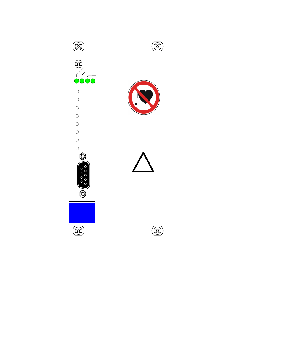
The following figure shows the front panel of the ES4455.1 Load Board.
ETAS
Load0
Load1
Load2
Load3
Threshold high Load 0
Threshold low Load 0
Threshold high Load 1
Threshold low Load 1
Threshold high Load 2
Threshold low Load 2
Threshold high Load 3
Threshold low Load 3
Threshold
calibrati on
connection
!
ES4455.1
Fig. 1-2 Front Panel of the ES4455.1 Load Board
The elements of the front panel are:
• The „Loadn“ LEDs indicating load current
• The LEDs which light up when the currents exceed a threshold set in
the (LABCAR-RTC) software
• The potentiometers for setting the lower and upper thresholds for
digitizing the output signal
• The “Threshold Calibration” connector at which the thresholds set
using the potentiometers are output
Introduction 7

1.3 Load Modules
The following load modules are currently available for the ES4455.1 Load
Board:
• PB4451CR Piggyback for 2 RB CRS Injectors
Simulation for injectors of the Bosch Common Rail System
• PB4451GDI Piggyback for 2 RB GDI Injectors
Simulation for injectors of the Bosch HDEV GDI system
For more information on the modules, refer to the chapter "Accessories"
on page 21.
“Pre-Assembled Solutions” with Integrated Load Modules
The ES4455.1 Load Board can also be supplied as an assembled version with
these modules under the following names:
• ES4450.2 Load Board for 4 RB CRS Injectors
The ES4450.2 enables the simulation of four injectors of the Bosch
Common Rail System (CRS). It consists of the ES4455.1 Load Board and
two piggybacks of the type “PB4451CR Piggyback for 2 RB CRS
Injectors”.
• ES4451.3 Load Board for 4 RB GDI Injectors
The ES4451.3 enables the simulation of four injectors of the Bosch
gasoline direct injection system. It consists of the ES4455.1 Load Board
and two piggybacks of the type “PB4451GDI Piggyback for 2 RB GDI
Injectors”.
Order Data
Order Name Short Name Order Number
PB4451CR Piggyback for 2 RB CRS
Injectors
PB4451GDI Piggyback for 2 RB GDI
Injectors
ES4450.2 Load Board for 4 RB CRS
Injectors
ES4451.3 Load Board for 4 RB GDI
Injectors
Ta b. 1 -1 Order Data for Load Modules and Pre-Assembled Solutions
Introduction8
PB4451CR F-00K-106-323
PB4451GDI F-00K-106-324
ES4450.2 F-00K-106-167
ES4451.3 F-00K-106-171

1.4 Taking the Product Back and Recycling
The European Union has passed a directive called Waste Electrical and
Electronic Equipment, or WEEE for short, to ensure that systems are setup
throughout the EU for the collection, treating and recycling of electronic
waste.
This ensures that the devices are recycled in a resource-saving way representing
no danger to health or the environment.
Fig. 1-3 WEEE Symbol
The WEEE symbol on the product or its packaging shows that the product
must not be disposed of as residual garbage.
The user is obliged to collect the old devices separately and return them to the
WEEE take-back system for recycling.
The WEEE directive concerns all ETAS devices but not external cables or
batteries.
For more information on the ETAS GmbH Recycling Program, contact the ETAS
sales and service locations (see "ETAS Contact Addresses" on page 25).
Introduction 9
 Loading...