

ETAS ES341.1, ES313.1, ES314.1 User Manual

ES341.1
Counter and Frequency Module with Sensor Supply (4 CH)
User’s Guide

Copyright
The data in this document may not be altered or amended without special notification from ETAS GmbH. ETAS GmbH undertakes no further obligation in relation to this document. The software described in it can only be used if the
customer is in possession of a general license agreement or single license. Using
and copying is only allowed in concurrence with the specifications stipulated in
the contract.
Under no circumstances may any part of this document be copied, reproduced,
transmitted, stored in a retrieval system or translated into another language
without the express written permission of ETAS GmbH.
© Copyright 2018 ETAS GmbH, Stuttgart
The names and designations used in this document are trademarks or brands
belonging to the respective owners.
ES341.1 - User’s Guide R03 EN - 04.2018
2

ETAS Contents
Contents
1 About this Manual . . . . . . . . . . . . . . . . . . . . . . . . . . . . . . . . . . . . . . . . . . . . . . . . . 6
1.1 Identification of Safety Notices . . . . . . . . . . . . . . . . . . . . . . . . . . . . . . . . . . . 6
1.2 Presentation of Information . . . . . . . . . . . . . . . . . . . . . . . . . . . . . . . . . . . . . 7
1.3 Scope of Supply . . . . . . . . . . . . . . . . . . . . . . . . . . . . . . . . . . . . . . . . . . . . . . 7
1.4 Additional Information . . . . . . . . . . . . . . . . . . . . . . . . . . . . . . . . . . . . . . . . . 7
2 Basic Safety Notices . . . . . . . . . . . . . . . . . . . . . . . . . . . . . . . . . . . . . . . . . . . . . . . . 8
2.1 General Safety Information . . . . . . . . . . . . . . . . . . . . . . . . . . . . . . . . . . . . . . 8
2.2 Requirements for Users and Duties for Operators . . . . . . . . . . . . . . . . . . . . . 8
2.3 Intended Use . . . . . . . . . . . . . . . . . . . . . . . . . . . . . . . . . . . . . . . . . . . . . . . . 8
3 ES300 Product Family . . . . . . . . . . . . . . . . . . . . . . . . . . . . . . . . . . . . . . . . . . . . . . 13
3.1 CAN Bus Cabling Concept . . . . . . . . . . . . . . . . . . . . . . . . . . . . . . . . . . . . . 13
3.2 Properties of the ES300 Series . . . . . . . . . . . . . . . . . . . . . . . . . . . . . . . . . . . 13
3.2.1 Advantages of the Decentral Cabling Concept. . . . . . . . . . . . . . . . 13
3.2.2 Additional Properties . . . . . . . . . . . . . . . . . . . . . . . . . . . . . . . . . . . 14
4 Hardware Description . . . . . . . . . . . . . . . . . . . . . . . . . . . . . . . . . . . . . . . . . . . . . . 15
4.1 Overview . . . . . . . . . . . . . . . . . . . . . . . . . . . . . . . . . . . . . . . . . . . . . . . . . . 15
4.2 Properties . . . . . . . . . . . . . . . . . . . . . . . . . . . . . . . . . . . . . . . . . . . . . . . . . . 15
4.3 Housing . . . . . . . . . . . . . . . . . . . . . . . . . . . . . . . . . . . . . . . . . . . . . . . . . . . 16
4.4 Connections . . . . . . . . . . . . . . . . . . . . . . . . . . . . . . . . . . . . . . . . . . . . . . . . 16
4.4.1 Overview . . . . . . . . . . . . . . . . . . . . . . . . . . . . . . . . . . . . . . . . . . . . 16
4.4.2 Daisy Chain . . . . . . . . . . . . . . . . . . . . . . . . . . . . . . . . . . . . . . . . . . 16
4.5 LEDs . . . . . . . . . . . . . . . . . . . . . . . . . . . . . . . . . . . . . . . . . . . . . . . . . . . . . . 17
5 Functional Description. . . . . . . . . . . . . . . . . . . . . . . . . . . . . . . . . . . . . . . . . . . . . . 18
5.1 Sensor Connections . . . . . . . . . . . . . . . . . . . . . . . . . . . . . . . . . . . . . . . . . . 18
5.1.1 Properties . . . . . . . . . . . . . . . . . . . . . . . . . . . . . . . . . . . . . . . . . . . 18
5.1.2 Sensor Supply . . . . . . . . . . . . . . . . . . . . . . . . . . . . . . . . . . . . . . . . 19
ES341.1 - User’s Guide 3

Contents ETAS
5.2 Measurement Methods . . . . . . . . . . . . . . . . . . . . . . . . . . . . . . . . . . . . . . . . 19
5.2.1 Frequency with Detection of Direction . . . . . . . . . . . . . . . . . . . . . . 19
5.2.2 Duty Cycle. . . . . . . . . . . . . . . . . . . . . . . . . . . . . . . . . . . . . . . . . . . 19
5.2.3 Period Duration . . . . . . . . . . . . . . . . . . . . . . . . . . . . . . . . . . . . . . . 20
5.2.4 Pulse Duration . . . . . . . . . . . . . . . . . . . . . . . . . . . . . . . . . . . . . . . . 20
5.2.5 Pause Time . . . . . . . . . . . . . . . . . . . . . . . . . . . . . . . . . . . . . . . . . . 20
5.2.6 Event Counter . . . . . . . . . . . . . . . . . . . . . . . . . . . . . . . . . . . . . . . . 20
5.2.7 Frequency / Event Counter with Detection of Direction . . . . . . . . . 20
5.3 Data Transmission . . . . . . . . . . . . . . . . . . . . . . . . . . . . . . . . . . . . . . . . . . . . 21
5.3.1 Design. . . . . . . . . . . . . . . . . . . . . . . . . . . . . . . . . . . . . . . . . . . . . . 21
5.3.2 Properties . . . . . . . . . . . . . . . . . . . . . . . . . . . . . . . . . . . . . . . . . . . 22
5.3.3 Transmission Speed . . . . . . . . . . . . . . . . . . . . . . . . . . . . . . . . . . . . 22
5.3.4 Synchronous Data Acquisition . . . . . . . . . . . . . . . . . . . . . . . . . . . . 22
5.4 Power Supply . . . . . . . . . . . . . . . . . . . . . . . . . . . . . . . . . . . . . . . . . . . . . . . 23
5.4.1 Supply Voltage . . . . . . . . . . . . . . . . . . . . . . . . . . . . . . . . . . . . . . . 23
5.4.2 Supply of the ES300 Modules via Connecting Line. . . . . . . . . . . . . 23
5.4.3 Additional Supply of the ES300 Modules via a Y Boost Cable. . . . . 23
5.5 Configuration . . . . . . . . . . . . . . . . . . . . . . . . . . . . . . . . . . . . . . . . . . . . . . . 24
5.6 Tool Integration . . . . . . . . . . . . . . . . . . . . . . . . . . . . . . . . . . . . . . . . . . . . . 24
5.7 Firmware Update . . . . . . . . . . . . . . . . . . . . . . . . . . . . . . . . . . . . . . . . . . . . 24
5.8 Calibration . . . . . . . . . . . . . . . . . . . . . . . . . . . . . . . . . . . . . . . . . . . . . . . . . 24
6 Commissioning . . . . . . . . . . . . . . . . . . . . . . . . . . . . . . . . . . . . . . . . . . . . . . . . . . . 25
6.1 General Installation Recommendations . . . . . . . . . . . . . . . . . . . . . . . . . . . . 25
6.1.1 Assembly Environment and Components for Fastening . . . . . . . . . 25
6.1.2 Potential Equalization in the Vehicle and Assembly of the Modules 25
6.2 Assembly . . . . . . . . . . . . . . . . . . . . . . . . . . . . . . . . . . . . . . . . . . . . . . . . . . 26
6.3 Applications . . . . . . . . . . . . . . . . . . . . . . . . . . . . . . . . . . . . . . . . . . . . . . . . 28
6.4 Cabling . . . . . . . . . . . . . . . . . . . . . . . . . . . . . . . . . . . . . . . . . . . . . . . . . . . . 28
6.4.1 Sensors . . . . . . . . . . . . . . . . . . . . . . . . . . . . . . . . . . . . . . . . . . . . . 28
6.4.2 Daisy-Chain Connections. . . . . . . . . . . . . . . . . . . . . . . . . . . . . . . . 29
7 Software Description. . . . . . . . . . . . . . . . . . . . . . . . . . . . . . . . . . . . . . . . . . . . . . . 30
7.1 Description . . . . . . . . . . . . . . . . . . . . . . . . . . . . . . . . . . . . . . . . . . . . . . . . . 30
7.2 System Requirements . . . . . . . . . . . . . . . . . . . . . . . . . . . . . . . . . . . . . . . . . 30
7.3 IPEaddon in INCA . . . . . . . . . . . . . . . . . . . . . . . . . . . . . . . . . . . . . . . . . . . . 30
7.4 Functions . . . . . . . . . . . . . . . . . . . . . . . . . . . . . . . . . . . . . . . . . . . . . . . . . . 31
7.4.1 CAN Bus Configuration . . . . . . . . . . . . . . . . . . . . . . . . . . . . . . . . . 31
7.4.2 Initialization. . . . . . . . . . . . . . . . . . . . . . . . . . . . . . . . . . . . . . . . . . 32
7.4.3 Setting Up Aliasing Filters . . . . . . . . . . . . . . . . . . . . . . . . . . . . . . . 34
7.4.4 Configuring ES300 Modules . . . . . . . . . . . . . . . . . . . . . . . . . . . . . 34
7.4.5 Configuring a Channel . . . . . . . . . . . . . . . . . . . . . . . . . . . . . . . . . 36
7.4.6 Adjustment . . . . . . . . . . . . . . . . . . . . . . . . . . . . . . . . . . . . . . . . . . 37
7.4.7 Import / Export Module Configuration. . . . . . . . . . . . . . . . . . . . . . 39
8 Technical Data . . . . . . . . . . . . . . . . . . . . . . . . . . . . . . . . . . . . . . . . . . . . . . . . . . . 40
8.1 General Data . . . . . . . . . . . . . . . . . . . . . . . . . . . . . . . . . . . . . . . . . . . . . . . 40
8.1.1 Identifications on the Product . . . . . . . . . . . . . . . . . . . . . . . . . . . . 40
8.1.2 Standards . . . . . . . . . . . . . . . . . . . . . . . . . . . . . . . . . . . . . . . . . . . 41
8.1.3 Ambient Conditions . . . . . . . . . . . . . . . . . . . . . . . . . . . . . . . . . . . 41
ES341.1 - User’s Guide4

ETAS Contents
8.1.4 Maintenance of the Product . . . . . . . . . . . . . . . . . . . . . . . . . . . . . 41
8.1.5 Cleaning the Product. . . . . . . . . . . . . . . . . . . . . . . . . . . . . . . . . . . 42
8.1.6 Mechanical data . . . . . . . . . . . . . . . . . . . . . . . . . . . . . . . . . . . . . . 42
8.2 RoHS Conformity . . . . . . . . . . . . . . . . . . . . . . . . . . . . . . . . . . . . . . . . . . . . 42
8.2.1 European Union . . . . . . . . . . . . . . . . . . . . . . . . . . . . . . . . . . . . . . 42
8.2.2 China . . . . . . . . . . . . . . . . . . . . . . . . . . . . . . . . . . . . . . . . . . . . . . 42
8.3 CE Marking . . . . . . . . . . . . . . . . . . . . . . . . . . . . . . . . . . . . . . . . . . . . . . . . 42
8.4 Product Return and Recycling . . . . . . . . . . . . . . . . . . . . . . . . . . . . . . . . . . . 42
8.5 Materials Subject to Declaration . . . . . . . . . . . . . . . . . . . . . . . . . . . . . . . . . 43
8.6 System Requirements . . . . . . . . . . . . . . . . . . . . . . . . . . . . . . . . . . . . . . . . . 43
8.6.1 Hardware . . . . . . . . . . . . . . . . . . . . . . . . . . . . . . . . . . . . . . . . . . . 43
8.6.2 Software . . . . . . . . . . . . . . . . . . . . . . . . . . . . . . . . . . . . . . . . . . . . 43
8.7 Electrical Data . . . . . . . . . . . . . . . . . . . . . . . . . . . . . . . . . . . . . . . . . . . . . . . 44
8.7.1 Voltage Supply . . . . . . . . . . . . . . . . . . . . . . . . . . . . . . . . . . . . . . . 44
8.7.2 Host Interface . . . . . . . . . . . . . . . . . . . . . . . . . . . . . . . . . . . . . . . . 44
8.7.3 Sensor Power Supply . . . . . . . . . . . . . . . . . . . . . . . . . . . . . . . . . . . 44
8.7.4 Input Channels . . . . . . . . . . . . . . . . . . . . . . . . . . . . . . . . . . . . . . . 46
8.8 Terminal Assignment . . . . . . . . . . . . . . . . . . . . . . . . . . . . . . . . . . . . . . . . . 47
8.8.1 LEMO CAN Bus . . . . . . . . . . . . . . . . . . . . . . . . . . . . . . . . . . . . . . . 47
8.8.2 LEMO Sensor Connection . . . . . . . . . . . . . . . . . . . . . . . . . . . . . . . 47
9 Cables and Accessories . . . . . . . . . . . . . . . . . . . . . . . . . . . . . . . . . . . . . . . . . . . . . 48
9.1 Measurement Cables . . . . . . . . . . . . . . . . . . . . . . . . . . . . . . . . . . . . . . . . . 48
9.2 Combined CAN Connection and Power Supply Cable . . . . . . . . . . . . . . . . . 49
9.2.1 CBCP300.1-3 . . . . . . . . . . . . . . . . . . . . . . . . . . . . . . . . . . . . . . . . 49
9.2.2 CBCP3005.1 . . . . . . . . . . . . . . . . . . . . . . . . . . . . . . . . . . . . . . . . . 49
9.2.3 CBCP301.1-3 . . . . . . . . . . . . . . . . . . . . . . . . . . . . . . . . . . . . . . . . 50
9.2.4 CBCP3015.1 . . . . . . . . . . . . . . . . . . . . . . . . . . . . . . . . . . . . . . . . . 50
9.3 CAN Chain Connection Cable . . . . . . . . . . . . . . . . . . . . . . . . . . . . . . . . . . . 51
9.4 CAN Termination Resistor Plug . . . . . . . . . . . . . . . . . . . . . . . . . . . . . . . . . . 51
9.5 Mounting Bracket . . . . . . . . . . . . . . . . . . . . . . . . . . . . . . . . . . . . . . . . . . . . 51
10 Ordering Information . . . . . . . . . . . . . . . . . . . . . . . . . . . . . . . . . . . . . . . . . . . . . . 52
10.1 ES341.1 . . . . . . . . . . . . . . . . . . . . . . . . . . . . . . . . . . . . . . . . . . . . . . . . . . . 52
10.2 Accessories . . . . . . . . . . . . . . . . . . . . . . . . . . . . . . . . . . . . . . . . . . . . . . . . . 52
10.2.1 Cables . . . . . . . . . . . . . . . . . . . . . . . . . . . . . . . . . . . . . . . . . . . . . . 52
10.2.2 Can Termination Resistor Plug . . . . . . . . . . . . . . . . . . . . . . . . . . . . 53
10.2.3 Mounting Bracket . . . . . . . . . . . . . . . . . . . . . . . . . . . . . . . . . . . . . 53
10.2.4 Calibration Service. . . . . . . . . . . . . . . . . . . . . . . . . . . . . . . . . . . . . 53
11 ETAS Contact Addresses . . . . . . . . . . . . . . . . . . . . . . . . . . . . . . . . . . . . . . . . . . . . 54
Figures . . . . . . . . . . . . . . . . . . . . . . . . . . . . . . . . . . . . . . . . . . . . . . . . . . . . . . . . . 55
Index . . . . . . . . . . . . . . . . . . . . . . . . . . . . . . . . . . . . . . . . . . . . . . . . . . . . . . . . . . 56
ES341.1 - User’s Guide 5
About this Manual ETAS
DANGER!
WARNING!
CAUTION!
1 About this Manual
This chapter contains information about the following topics:
• "Identification of Safety Notices" on page 6
• "Presentation of Information" on page 7
• "Scope of Supply" on page 7
• "Additional Information" on page 7.
1.1 Identification of Safety Notices
The safety notices contained in this manual are identified with the danger symbol
shown below:
The safety notices shown below are used for this purpose. They provide notes to
extremely important information. Please read this information carefully.
indicates an immediate danger with a high risk of death or serious
injury, if not avoided.
indicates a possible danger with moderate risk of death or (serious)
injury, if not avoided.
identifies a hazard with low risk that could result in minor or medium
physical injuries or property damages if not avoided.
ES341.1 - User’s Guide6

ETAS About this Manual
Note
1.2 Presentation of Information
All activities to be performed by the user are presented in a "Use Case" format.
That is, the goal to be accomplished is briefly defined in the heading, and the
respective steps required for reaching this goal are then presented in a list. The
presentation looks as follows:
Goal definition:
any advance information...
1. Step 1
Any explanation for step 1...
2. Step 2
Any explanation for step 2...
3. Step 3
Any explanation for step 3...
Any concluding comments...
Typographical conventions
The following typographical conventions are used:
Bold Labels of the device
Italic Particularly important text passages
Other conventions
• Select Database New means, "Select the ’New’ button menu item
from the ’Database’ menu".
• Click on OK means, "Click on the ’OK’ button".
Important notes for the user are presented as follows:
Important note for the user.
1.3 Scope of Supply
Prior to the initial commissioning of the module, please check whether the module was delivered with all required components and cables (see chapter 10
on page 52).
Additional cables and adapters can be obtained separately from ETAS. A list of
available accessories and their order designation is located in chapter "Ordering
Information" on page 52 of this manual or in the ETAS product catalog.
1.4 Additional Information
The configuration instructions for the module under INCA can be found in the
corresponding software documentation.
ES341.1 - User’s Guide 7

Basic Safety Notices ETAS
Note
2 Basic Safety Notices
This chapter contains information about the following topics:
• "General Safety Information" on page 8
• "Requirements for Users and Duties for Operators" on page 8
• "Intended Use" on page 8.
2.1 General Safety Information
Please observe the Product Safety Notices ("ETAS Safety Notice") and the following safety notices to avoid health issues or damage to the device.
Carefully read the documentation (Product Safety Advice and this User's Guide)
that belongs to the product prior to the startup.
ETAS GmbH does not assume any liability for damages resulting from improper
handling, unintended use or non-observance of the safety precautions.
2.2 Requirements for Users and Duties for Operators
The product may be assembled, operated and maintained only if you have the
necessary qualification and experience for this product. Improper use or use by a
user without sufficient qualification can lead to damages or injuries to one’s
health or damage to property.
The system integrator is responsible for the safety of systems that use the product.
General safety at work
Existing specifications regarding health and safety and accident prevention must
be observed. All applicable regulations and statutes regarding operation must be
strictly followed when using this product.
2.3 Intended Use
Application area of the product
This product was developed and approved for applications in the automotive
sector. The module is suitable for use in the engine compartment of vehicles.
For use in other application areas, please contact your ETAS contact partner.
Requirements for the technical state of the product
The product is designed in accordance with state-of-the-art technology and recognized safety rules. The product may be operated only in a technically flawless
condition and according to the intended purpose and with regard to safety and
dangers as stated in the respective product documentation. If the product is not
used according to its intended purpose, the protection of the product may be
impaired.
ES341.1 - User’s Guide8

ETAS Basic Safety Notices
CAUTION!
Requirements for operation
• Use the product only according with the specifications in the relevant
User's Guide. Any other usage could jeopardize product safety.
• Observe the requirements on the ambient conditions.
• Do not use the product in potentially explosive areas.
Risk of burning on hot surfaces of the module!
Do not touch the surfaces of the module during operation at high
ambient temperatures.
The surface temperature of the module can reach 90 °C when it is
used in a vehicle and at an ambient temperature of 70 °C.
Electrical safety and power supply
• Please comply with all electrical safety regulations and all health and
safety laws and specifications valid at the place of use!
• Connect only current circuits with safety extra-low voltage in accordance
with EN 61140 (degree of protection III) to the connections of the module.
• Ensure the compliance with the connection and adjustment values (see
the information in the chapter 8 on page 40).
• Do not apply any voltages to the connections of the module that do not
correspond to the specifications of the respective connection.
Power supply
• The power supply for the product must be safely disconnected from the
supply voltage. For example, use a car battery or a suitable lab power supply.
• Use exclusively lab power supplies with double protection to the supply
system (with double insulation / with reinforced insulation (DI / RI)).
• The lab power supply must be approved for an operating altitude of
3,000 m / 9,842 ft. and for an ambient temperature of up to 105 °C.
• The vehicle battery could be discharged when the modules are in operation.
ES341.1 - User’s Guide 9
Basic Safety Notices ETAS
DANGER!
Connection to the power supply
• The power supply cable must not be directly connected to the vehicle battery or lab power supply, but rather via a suitable protection mechanism.
• Make sure the connections to the lab power supply, the power supply on
the module and on the vehicle battery are easily accessible!
• Route the power cord in such a way that it is protected against abrasion,
damages, deformation and kinking!
• Do not place any objects on the power cord!
Dangerous electrical voltage!
Only connect the power supply cable to a suitable vehicle battery or
a suitable lab power supply! Connecting to a mains socket is not
allowed!
To prevent the connector from accidentally being plugged into a
mains socket, ETAS recommends using power supply cables with
safety banana plugs in areas with mains sockets..
De-energizing the module
The module does not have a power switch. The module can be de-energized as
follows:
• Disconnecting the cables from the measurement inputs
and
• Disconnecting the module from the power supply
– Switching off the lab power supply
or
– Disconnecting the module from the lab power supply
Disconnect device is the lab connector on the power supply cable or
the plug on the power supply cable at the module connection
or
Disconnect device is the lab connector on the power supply cable or
the plug on the power supply cable at the module connection
or
– Disconnecting the vehicle battery.
ES341.1 - User’s Guide10
ETAS Basic Safety Notices
CAUTION!
CAUTION!
CAUTION!
Cabling
Approved cables:
• Use exclusively ETAS cables at the connections of the module!
• Adhere to the maximum permissible cable lengths!
• Do not use any damaged cables! Cables may be repaired only by ETAS!
Never apply force to insert a plug into a socket.
Ensure that there is no contamination in and on the connection, that
the plug fits the socket, and that you correctly aligned the plugs with
the connection.
Potential equalization in the vehicle is possible via the shield of
the connecting cables of the modules!
Install the modules only at locations with the same electrical potential
or isolate the modules from the installation location.
Requirements for the place of installation
• Place the module or the module block on a smooth, even and firm foundation.
• The module or module block must always be securely fixed.
Requirements on the ventilation
• Keep the module away from heat sources and protect it against direct
exposure to the sun.
• The free space above and behind the module must be selected so that
sufficient air circulation is ensured.
Fixing the module on a carrier system
When selecting the carrier system, note the static and dynamic forces which
could occur as a result of the module or module block on the carrier system.
Damage or destruction of the module is possible.
Risk of damage or destruction of the modules. Modules of the ES300
series are only approved for installation and operation on components or at places where compliance with the technical data of the
module is guaranteed, e.g.:
• vibration resistance of modules (for example, modules only
mounted on sprung masses, but not on wheel suspensions or
directly on the engine) and
• temperature resistance of modules (for example, modules not
mounted on the engine, turbocharger, exhaust manifold or their
immediate surrounds).
ES341.1 - User’s Guide 11

Basic Safety Notices ETAS
CAUTION!
CAUTION!
During the installation of the modules, note the permissible temperature range of the cable ties used!
Damage of the product and loss of properties in accordance with IP67
Loss of properties in accordance with IP67!
Do not open or modify the product housing.
Work on the product housing may be performed only by qualified
technical personnel.
Transport
• Do not block and connect the modules until they are at their commissioning location!
• Do not transport the modules at the cable of the module or any other
cables.
Maintenance
The product is maintenance-free.
Repair
If an ETAS hardware product should require a repair, return the product to ETAS.
Cleaning the module housing
• Use a dry or lightly moistened, soft, lint-free cloth for cleaning the module
housing.
• Do not use any sprays, solvents or abrasive cleaners which could damage
the housing.
• Ensure that no moisture enters the housing. Never spray cleaning agents
directly onto the module.
ES341.1 - User’s Guide12

ETAS ES300 Product Family
3 ES300 Product Family
This chapter contains information about the following topics:
• "CAN Bus Cabling Concept" on page 13
• "Properties of the ES300 Series" on page 13
3.1 CAN Bus Cabling Concept
In a test vehicle, several hundred sensors must be installed in many areas for the
testing phase, e.g. in the engine compartment and in the ground area. The sensors distributed over the entire vehicle must then be connected with the measuring devices of the test setup.
Today's standard solutions with a central setup of the measuring devices in the
passenger compartment require a complex cabling of the widely distributed sensors with the measuring devices. Numerous, mostly long connecting cables
between sensors and measuring devices, combined into several thick cable harnesses, demand a heavily modified fire wall of the test vehicle. This causes long
setup times and high costs.
With the ES300 modules, ETAS offers a decentral solution that significantly simplifies the measuring set-up of the sensors.
The basic idea of this concept is to install the modules of the ES300 series spatially as close as possible to the sensors, to chain the modules with each other
and to connect only the first module of this chain with the laptop in the vehicle.
The ES300 modules from ETAS are independent measuring modules that pass
the measuring signals over the CAN bus. They can be operated individually as
well as in combination with other modules from ETAS.
3.2 Properties of the ES300 Series
3.2.1 Advantages of the Decentral Cabling Concept
• The compact ES300 modules can be installed close to the sensors with
short connecting cables.
• The simple assembly and cabling principle (daisy-chain topology) of the
modules
– requires only on common cable between the modules for the power
supply and the transmission of data,
– significantly reduces the setup times for the tests, and
– simplifies the maintenance and expansion of the measuring setup.
• Only the laptop has to be accommodated in the vehicle, which is connected with the modules using a single cable.
• Test vehicles equipped with a ES300 measuring system can be used in a
flexible way since the vehicles do not have to be modified for changed or
new test assignments.
ES341.1 - User’s Guide 13

ES300 Product Family ETAS
3.2.2 Additional Properties
In addition to the advantages of the decentral cabling, additional properties of
the ES300 series are provided here at a glance:
• The design of the ES300 modules is very compact.
• Each of the modules features an LED for localizing the module.
• Automotive-qualified modules that are suitable for use in the lab and in
the vehicle on test tracks:
– Housing, connections and cables water-proof and dust-proof to IP67,
designed for use in the engine compartment of the vehicle.
– Robust to accelerations and mechanical damages
– Robust to ambient conditions (temperature, humidity, EMC)
– Very low temperature coefficients contribute to a reduction in measur-
ing errors.
• All channels fully electrically isolated
• Dovetailing for tool-free module connection of the ES300 modules
• Different channel sampling rates
• Part of the ETAS Tool Suite
The complete technical data is located in chapter 8 on page 40.
ES341.1 - User’s Guide14
ETAS Hardware Description
4 Hardware Description
This chapter contains information about the following topics:
• "Overview" on page 15
• "Properties" on page 15
• "Housing" on page 16
• "Connections" on page 16
• "LEDs" on page 17
4.1 Overview
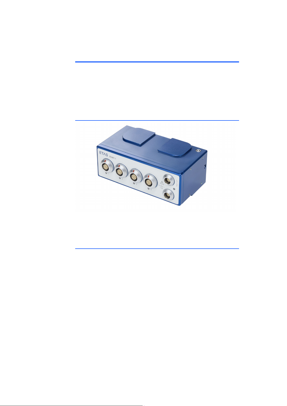
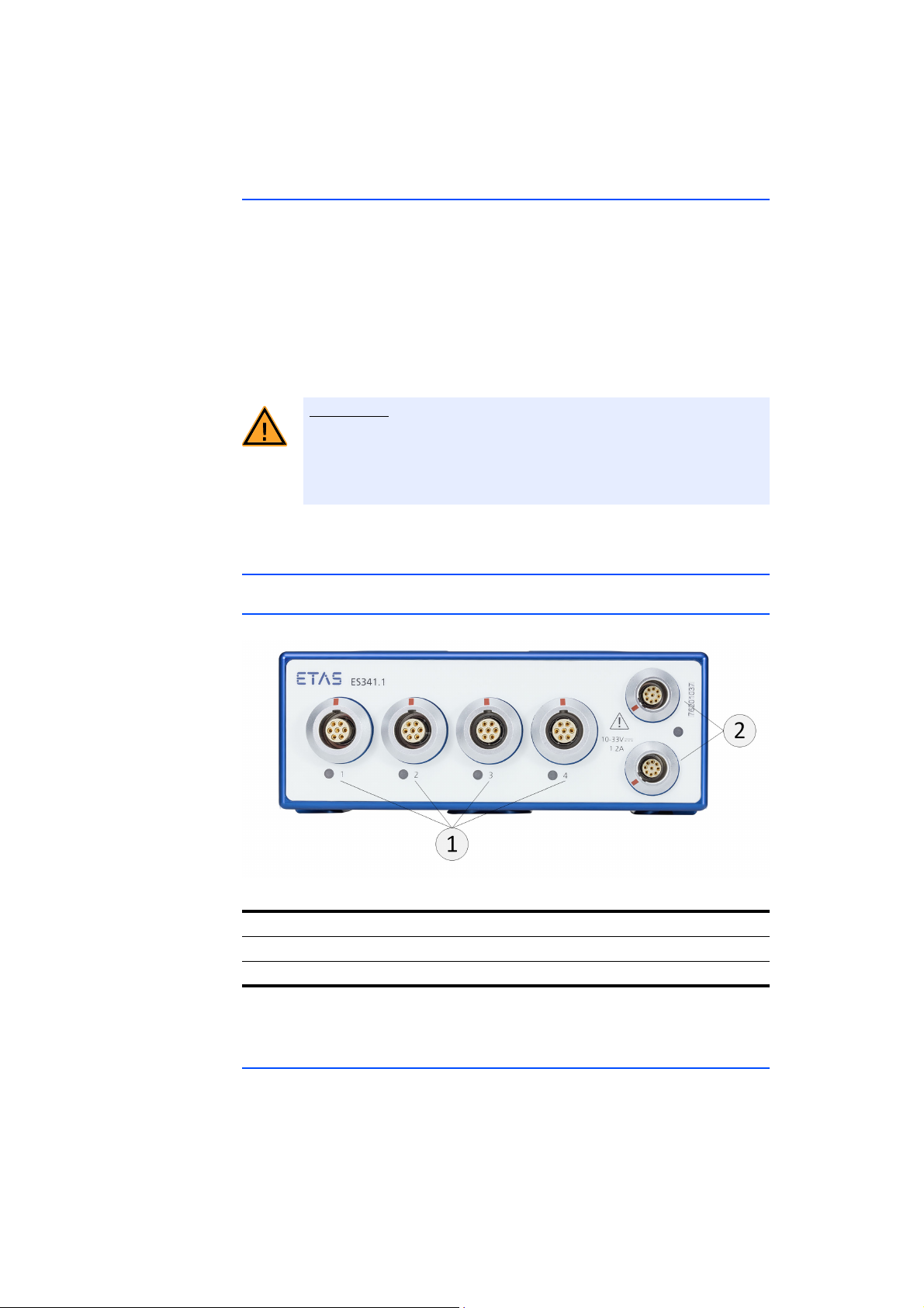
Fig. 4-1 ES341.1 Housing
The counter and frequency module with ES341.1 sensor supply is part of the
series of ES300 modules. The ES341.1 can sample digital signals at 4 input channels. A sensor supply is available for each channel.
4.2 Properties
• 4 electrically isolated measuring channels with adjustable trigger thresholds
• Measuring modes: Frequency over period duration, period/pulse/pause
time, duty cycle, event count, detection of direction of rotation (frequency
mode, event counting)
• Electrical isolation of measuring channels among each other and from the
supply voltage
• 4 separately adjustable sensor supplies (up to 15 V, 60 mA)
• Status LED at every measuring input (signal recording display)
• Measuring data output to CAN
• Designed for direct installation in the engine compartment
• Tool-free connection technology
The complete technical data of the ES341.1 is located in chapter 8 on page 40.
ES341.1 - User’s Guide 15
Hardware Description ETAS
CAUTION!
4.3 Housing
The ES341.1 utilizes a robust metal housing with connections at the front of the
unit. The ES341.1 is designed for installation in the engine compartment.
The housings of the ES300 series can be connected with each other quickly and
easily to form a measuring system (see chapter 6 on page 25). In the vehicle or in
the lab, the modules can be screwed directly onto a carrier system without much
effort or fastened with cable ties.
These simple and uncomplicated fastening options allow for a flexible assembly
of the modules. On top of that, a high degree of availability of the fastening
options is also given under rough harsh ambient conditions (salt mist, dirt).
Loss of Properties After IP67!
Do not open or change the module housing!
Work on the module housing may only be performed by qualified
personnel.
4.4 Connections
4.4.1 Overview
All plug connections of the ES300 modules are located on the front (see Fig. 4-2).
Fig. 4-2 ES341.1 connections
No. in Fig. 4-2 Connection Meaning
1 LEMO Measurement input
2 LEMO CAN bus and power supply
The LEMO plug connectors used are installed in accordance with degree of protection IP67.
4.4.2 Daisy Chain
The modules are connected using a daisy-chain topology. The input and output
sockets are freely selectable. The CAN data line and the voltage supply are
looped through the daisy-chain connections of the module.
ES341.1 - User’s Guide16
ETAS Hardware Description
One connection is connected to the bus interface module. The other connection
is connected with the following module of the ES300 series or the CAN terminating resistor is connected to the connection at the last module of the chain.
4.5 LEDs
The ES341.1 features a status LED for the display of the operating state.
LED code Display State
off No power supply
Illuminated green Operational
Flashing green
(0.1 s on / 0.9 s off)
Illuminated red
Flashing red
(0.5 s on / 0.5 s off)
Flashing red
(0.1 s on / 0.1 s off)
Measurement running
Error during the configuration, initialization of the measurement or
communication.
Remedy:
1. Switch the module off and on
again.
2. If the problem persists, restart the
configuration software.
3. If the problem still persists, take
the module out of the chain and
connect it separately with the PC.
4. If the problem still persists, send
the module to ETAS for repair.
Error in the CAN bus communication.
Remedy:
Proceed in the same ways as for an
LED illuminated red.
Error during basic initialization of the
module - configuration does not
match.
Remedy:
1. Follow steps 1-3 of the remedy for
the LED illuminated red.
2. If the problem persists, start a
firmware update.
3. If the problem still persists, send
the module to ETAS for repair.
ES341.1 - User’s Guide 17
Functional Description ETAS
logical 0
logical 1
HIGH
level
LOW
level
5 Functional Description
This chapter contains information about the following topics:
• "Sensor Connections" on page 18
• "Measurement Methods" on page 19
• "Data Transmission" on page 21
• "Power Supply" on page 23
• "Configuration" on page 24
• "Tool Integration" on page 24
• "Firmware Update" on page 24
• "Calibration" on page 24
5.1 Sensor Connections
5.1.1 Properties
All sensor connections of ES341.1 feature identical designs. They consist of an
input stage with signal recording and signal processing.
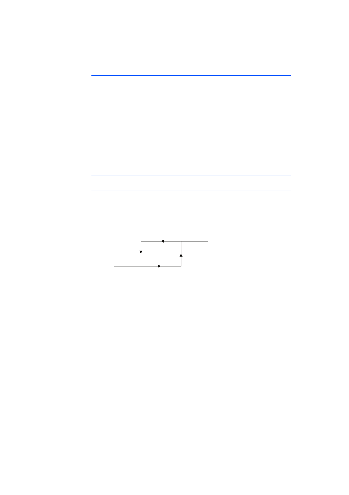
Configurable hysteresis
The hysteresis and the corresponding values for the levels LOW and HIGH can be
configured independent of each other in the application software (see
Fig. 5-1 Definition of hysteresis for the input channel
They can be configured separately in a range from -40 V to +40 V for every input
channel of the ES341.1. The minimum resolution of the switching thresholds
measures 0.025 V. The minimum resolution of the switching thresholds measures
0.025 V.
The configurable hysteresis causes a noise suppression. This property facilitates
its application in environments with noise interferences or in case of noisy signals. The quality of the signal interpretation is significantly improved.
Electrical isolation
The sensor connections are electrically isolated to each other and to the power
supply.
Interference voltage level
An interference voltage filter in the input stage clears the input signal of short
interference peaks. The filter characteristic (duration) can be configured in the
application software. The interference voltage filter can be switched off as
needed.
ES341.1 - User’s Guide18
 Loading...