

ETAS ES1222.4-A User Manual

bpNOOOKQJ^
`^k=~åÇ=hJiáåÉ=_ç~êÇ
User’s Guide

Copyright
The data in this document may not be altered or amended without special
notification from ETAS GmbH. ETAS GmbH undertakes no further obligation in
relation to this document. The software described in it can only be used if the
customer is in possession of a general license agreement or single license.
Using and copying is only allowed in concurrence with the specifications stipulated in the contract.
Under no circumstances may any part of this document be copied, reproduced, transmitted, stored in a retrieval system or translated into another language without the express written permission of ETAS GmbH.
© Copyright 2006 ETAS GmbH
The names and designations used in this document are trademarks or brands
belonging to the respective owners.
Document QH122204 R1.0.2 EN TTN F 00K 103 563
ES1222.4-A CAN and K-Line Board2

`зенЙенл
1 Introduction . . . . . . . . . . . . . . . . . . . . . . . . . . . . . . . . . . . . . . . . . . . . . . . . . . . . . 7
1.1 Features . . . . . . . . . . . . . . . . . . . . . . . . . . . . . . . . . . . . . . . . . . . . . . . . . . 7
1.1.1 CAN Interface. . . . . . . . . . . . . . . . . . . . . . . . . . . . . . . . . . . . . . . 7
1.1.2 K-Line and L-Line Interface . . . . . . . . . . . . . . . . . . . . . . . . . . . . . 7
1.1.3 General . . . . . . . . . . . . . . . . . . . . . . . . . . . . . . . . . . . . . . . . . . . 8
1.2 Applications . . . . . . . . . . . . . . . . . . . . . . . . . . . . . . . . . . . . . . . . . . . . . . . 8
1.3 System Requirements . . . . . . . . . . . . . . . . . . . . . . . . . . . . . . . . . . . . . . . . 9
1.3.1 Hardware Requirements . . . . . . . . . . . . . . . . . . . . . . . . . . . . . . . 9
1.3.2 Software Support . . . . . . . . . . . . . . . . . . . . . . . . . . . . . . . . . . . . 9
1.4 General Safety Instructions . . . . . . . . . . . . . . . . . . . . . . . . . . . . . . . . . . . . 9
2 Hardware . . . . . . . . . . . . . . . . . . . . . . . . . . . . . . . . . . . . . . . . . . . . . . . . . . . . . . 11
2.1 Front Panel . . . . . . . . . . . . . . . . . . . . . . . . . . . . . . . . . . . . . . . . . . . . . . . 11
2.2 Block Diagram . . . . . . . . . . . . . . . . . . . . . . . . . . . . . . . . . . . . . . . . . . . . . 11
2.3 Interfaces . . . . . . . . . . . . . . . . . . . . . . . . . . . . . . . . . . . . . . . . . . . . . . . . 12
2.3.1 Serial CANbus Interface . . . . . . . . . . . . . . . . . . . . . . . . . . . . . . 12
2.3.2 Serial Diagnostic Interface. . . . . . . . . . . . . . . . . . . . . . . . . . . . . 13
2.3.3 VME64bus Interface . . . . . . . . . . . . . . . . . . . . . . . . . . . . . . . . . 14
2.3.4 Analog Output . . . . . . . . . . . . . . . . . . . . . . . . . . . . . . . . . . . . . 14
2.4 Ipetronik Modules . . . . . . . . . . . . . . . . . . . . . . . . . . . . . . . . . . . . . . . . . . 14
Contents 3

2.5 Hardware Configuration . . . . . . . . . . . . . . . . . . . . . . . . . . . . . . . . . . . . . 15
2.5.1 Jumpers JP1-JP3 . . . . . . . . . . . . . . . . . . . . . . . . . . . . . . . . . . . . 16
2.5.2 Slot . . . . . . . . . . . . . . . . . . . . . . . . . . . . . . . . . . . . . . . . . . . . . 16
2.5.3 Firmware Update . . . . . . . . . . . . . . . . . . . . . . . . . . . . . . . . . . . 16
3 Technical Data . . . . . . . . . . . . . . . . . . . . . . . . . . . . . . . . . . . . . . . . . . . . . . . . . . 17
3.1 Pin Assignment . . . . . . . . . . . . . . . . . . . . . . . . . . . . . . . . . . . . . . . . . . . . 17
3.1.1 CAN1-CAN4. . . . . . . . . . . . . . . . . . . . . . . . . . . . . . . . . . . . . . . 17
3.1.2 K-Line/ L-Line . . . . . . . . . . . . . . . . . . . . . . . . . . . . . . . . . . . . . . 18
3.1.3 Backplane Connector . . . . . . . . . . . . . . . . . . . . . . . . . . . . . . . . 19
3.2 Electrical Data . . . . . . . . . . . . . . . . . . . . . . . . . . . . . . . . . . . . . . . . . . . . . 20
3.2.1 Processor and Measurement Data Memory. . . . . . . . . . . . . . . . 20
3.2.2 Interfaces . . . . . . . . . . . . . . . . . . . . . . . . . . . . . . . . . . . . . . . . . 20
3.2.3 VMEbus Interface . . . . . . . . . . . . . . . . . . . . . . . . . . . . . . . . . . 21
3.2.4 Power Supply . . . . . . . . . . . . . . . . . . . . . . . . . . . . . . . . . . . . . . 21
3.3 General Data . . . . . . . . . . . . . . . . . . . . . . . . . . . . . . . . . . . . . . . . . . . . . . 22
3.3.1 Physical Dimensions . . . . . . . . . . . . . . . . . . . . . . . . . . . . . . . . . 22
3.3.2 Environmental Conditions . . . . . . . . . . . . . . . . . . . . . . . . . . . . 22
3.3.3 Fulfilled Standards and Norms . . . . . . . . . . . . . . . . . . . . . . . . . 22
4 Cables and Accessories. . . . . . . . . . . . . . . . . . . . . . . . . . . . . . . . . . . . . . . . . . . . 23
4.1 CAN Interface Cable . . . . . . . . . . . . . . . . . . . . . . . . . . . . . . . . . . . . . . . . 23
4.1.1 CAN Cable K106 . . . . . . . . . . . . . . . . . . . . . . . . . . . . . . . . . . . 23
4.1.2 CAN Cable K107 . . . . . . . . . . . . . . . . . . . . . . . . . . . . . . . . . . . 23
4.1.3 CAN Cable K15 . . . . . . . . . . . . . . . . . . . . . . . . . . . . . . . . . . . . 24
4.1.4 CAN Cable CBAC130.1-3. . . . . . . . . . . . . . . . . . . . . . . . . . . . . 24
4.1.5 CAN Cable CBCX130.1-2. . . . . . . . . . . . . . . . . . . . . . . . . . . . . 24
4.1.6 CAN Interface Cable K95 . . . . . . . . . . . . . . . . . . . . . . . . . . . . . 25
4.2 CAN Termination Plugs . . . . . . . . . . . . . . . . . . . . . . . . . . . . . . . . . . . . . . 25
4.2.1 CAN Termination Plug KS1 (120 Ohm) . . . . . . . . . . . . . . . . . . . 25
4.2.2 CAN Termination Connector KS2 (120 Ohm, SUB-D) . . . . . . . . 25
4.2.3 CAN Termination Plug CBCX131.1-0 (120 Ohm, SUB-D). . . . . . 26
4.3 K-Line Cable . . . . . . . . . . . . . . . . . . . . . . . . . . . . . . . . . . . . . . . . . . . . . . 26
4.3.1 K-Line Cable CBK100 . . . . . . . . . . . . . . . . . . . . . . . . . . . . . . . . 26
4.3.2 K-Line Cable K78 . . . . . . . . . . . . . . . . . . . . . . . . . . . . . . . . . . . 27
4.3.3 K-Line Cable K96 . . . . . . . . . . . . . . . . . . . . . . . . . . . . . . . . . . . 27
4.3.4 Cable Adapter KA45 . . . . . . . . . . . . . . . . . . . . . . . . . . . . . . . . 27
4.3.5 Cable Adapter K72. . . . . . . . . . . . . . . . . . . . . . . . . . . . . . . . . . 28
4.3.6 Cable Adapter K18 (K-Line Extension). . . . . . . . . . . . . . . . . . . . 28
Contents4

5 Ordering Information . . . . . . . . . . . . . . . . . . . . . . . . . . . . . . . . . . . . . . . . . . . . . 29
5.1 ES1222.4-A . . . . . . . . . . . . . . . . . . . . . . . . . . . . . . . . . . . . . . . . . . . . . . 29
5.2 Accessoires . . . . . . . . . . . . . . . . . . . . . . . . . . . . . . . . . . . . . . . . . . . . . . . 29
5.2.1 CAN Cable Sub-D . . . . . . . . . . . . . . . . . . . . . . . . . . . . . . . . . . 29
5.2.2 CAN Cable Lemo OS . . . . . . . . . . . . . . . . . . . . . . . . . . . . . . . . 29
5.2.3 CAN Termination Plug . . . . . . . . . . . . . . . . . . . . . . . . . . . . . . . 29
5.2.4 CAN Adapter . . . . . . . . . . . . . . . . . . . . . . . . . . . . . . . . . . . . . . 30
5.2.5 K-Line Cable . . . . . . . . . . . . . . . . . . . . . . . . . . . . . . . . . . . . . . 30
6 Glossary . . . . . . . . . . . . . . . . . . . . . . . . . . . . . . . . . . . . . . . . . . . . . . . . . . . . . . . 31
7 ETAS Contact Addresses . . . . . . . . . . . . . . . . . . . . . . . . . . . . . . . . . . . . . . . . . . . 33
List of Figures . . . . . . . . . . . . . . . . . . . . . . . . . . . . . . . . . . . . . . . . . . . . . . . . . . . 35
List of Tables. . . . . . . . . . . . . . . . . . . . . . . . . . . . . . . . . . . . . . . . . . . . . . . . . . . . 37
Index . . . . . . . . . . . . . . . . . . . . . . . . . . . . . . . . . . . . . . . . . . . . . . . . . . . . . . . . . 39
Contents 5

Contents6

1 Introduction
This section contains information about the basic features and applications of
the ES1222.4-A board.
note
Some components of the board may be damaged or destroyed by electrostatic
discharges. Please keep the board in its storage package until it is installed.
The board should only be taken from its storage package, configured and
installed at a work place that is protected against static discharge.
1.1 Features
The ES1222.4-A board has four CAN interfaces as well as a K-Line and L-Line
interface. A VME64 slave interface enables integration to VMEbus systems,
such as the ES1000 system. The board makes it possible to access serial ECU
interfaces.
1.1.1 CAN Interface
The CAN interface has the following features:
• 4 independent, DC decoupled CAN interfaces
• CAN protocol V2.0a (standard identifier)
• CAN protocol V2.0b (extended identifier)
• CAN Calibration Protocol V2.0/V2.1 (standardized ASAP1a CCP)
• KWP2000 on CAN
• XCP on CAN
• UDS on CAN (ISO 14229/ ISO 15765)
• ISO high-speed physical layer
• Baud rates of up to 1 MBaud can be set using software
• Intel 82C527 communication controller
• Connection of measuring instruments which communicate via CAN, e.g.
IPETRONIK modules
1.1.2 K-Line and L-Line Interface
The K-Line and L-Line interface has the following features:
• Galvanic isolation from VMEbus
• Conforms to ISO 9141-2 requirements for diagnostic testers
• Transfer rates of up to 250 kBaud
Introduction 7

• K-Line: automatic configuration on 12 V and 24 V operation voltage
• Protocols: McMess, KWP2000, Keyword71
• Dallas DS87C520 communication controller
1.1.3 General
The ES1222.4-A board has the following features:
• Integrated in ASCET-RP, INTEGRIO and INCA
• Firmware of the
• Up to four ES1222.4-A can be operated simultaneously on an ES1000
• Motorola MPC555 with 40 MHz to reduce the system processor load
• Independent bus systems for communication controllers and MPC555
• VME64 slave interface
• integrated programming module for generating programming voltage for
• Connector solution for extrem mechanical load in the vehicle
• Automotive temperature range: -40° C to +85° C/ -40° F to +185° F
ES1222.4-A can be updated using the service software
HSP running on the connected PC while the board is mounted in the
ES1000 system
– 1 MByte SRAM
– 1 MByte Flash
Flash EPROMs in ECUs
1.2 Applications
You can use the ES1222.4-A board for the following tasks:
• connecting external devices using the CAN interface with VMEbus systems
• ECU calibration using CANbus and/or diagnostic interface
• ECU diagnostics
• Flash programming of ECUs
• measuring external measurands using Ipetronik modules
• recording and acquiring communication data in one or more CAN networks
• simulation of CAN interfaces in CAN networks
Introduction8

1.3 System Requirements
This section tells you which hardware and software are needed to operate your
ES1222.4-A.
note
Carefully check the software version numbers and cable names. Wrong software
versions and cables could impair the proper functioning of your ES1222.4-A
damage the ES1222.4-A and the connected devices.
1.3.1 Hardware Requirements
You need an ETAS VME system ES1000.2 or ES1000.3 for the ES1222.4-A
board. The ES1222.4-A is not supported by an ES1000.1 or an INCA-VME system.
1.3.2 Software Support
You need following software versions to support the ES1222.4-A board:
Software Min. Version
HSP 3.2.0
INCA 5.1.1
ASCET-RP 5.2.0
INTECRIO 1.1.0
1.4 General Safety Instructions
Please be aware that this board interacts with the application system. These
interactions alter the application system behavior. Failures or unexpected operational results may be critical to the application system behavior.
Attention
Using the board is only allowed in application systems with additional
safe or redundant systems (e.g. emergency stop, backup system).
Using the board in any way other than described in this documentation is not permissible and can lead to connected products being
damaged or destroyed.
The safety instructions must be heeded at all times!
Liability cannot be accepted for damage caused by non adherence to the
instructions contained in this document.
Introduction 9

Introduction10
2 Hardware
This chapter contains information about interfaces, hardware configuration,
usage of Ipetronik modules and firmware update of the ES1222.4-A board.
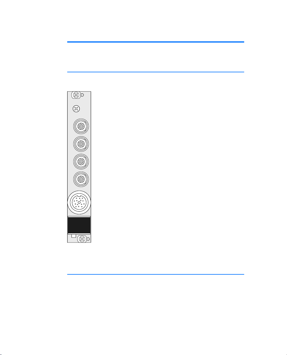
2.1 Front Panel
The following figure shows the front panel of the ES1222.4-A board, detailing
the position of the interface connectors.
CAN 1CAN 2CAN 3CAN 4
K-Li ne
ES1222.4
A
Fig. 2-1 ES1222.4-A Front Panel
2.2 Block Diagram
The following block diagram shows how the ES1222.4-A board works.
Fig. 2-2 on page 12 represents the ES1222.4-A in a simplified diagram with
the ECU interfaces on the left and the controller unit and the slave VMEbus
slave interface on the right.
Hardware 11
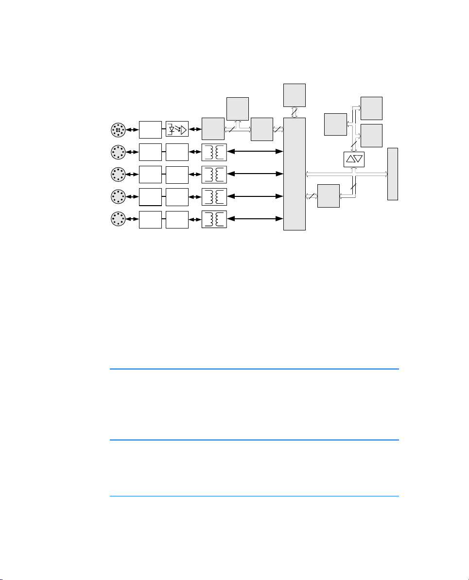
Both the communication controller and the MPC555 microprocessor have their
own bus system. The two bus systems are connected via a buffer.
pao^j
hJiáåÉ
`^k=N
`^k=O
`^k=P
`^k=Q
hJiбеЙ
aкбоЙк
`^k
qк~елЕЙбоЙк
`^k
qк~елЕЙбоЙк
`^k
qк~елЕЙбоЙк
`^k
qк~елЕЙбоЙк
`^k
`зенкзддЙк
`^k
`зенкзддЙк
`^k
`зенкзддЙк
`^k
`зенкзддЙк
jáÅêçJ
ЕзенкзддЙк
cä~ëÜ
128 KB
U
amo^j
16 KB
16 MB
NS
U
a~н~=^Еимблбнбзе=C
jЙ~лмкЙгЙен=`зенкзддЙк=Ea^j`F
jáÅêçJ
ЕзенкзддЙк
amo^j
128 KB
PO
cä~ëÜ
1 MB
po^j
1 MB
PO
PO
Fig. 2-2 Block Diagram
The VME slave interface contains the buffers for data and address lines as well
as the interrupt logic.
The two dual-ported RAMs can be accessed both from the VMEbus and the
communication controller.
The communication controller makes four CAN interfaces available as well as
the K-Line and L-Line interfaces. Their signals are routed to the connectors on
the front panel via dc decoupling.
At an analog output a programm voltage for Flash EPROMs is available.
pä~îÉ
sjbДмл=fенЙкС~ЕЙ
2.3 Interfaces
The ES1222.4-A board has four CANbus interfaces and a serial K-Line and LLine interface for connecting VMEbus systems with external devices.
It also has a communication controller for data exchange via the serial interfaces. This guarantees high data transfer rates.
2.3.1 Serial CANbus Interface
The ES1222.4-A board has four CANbus interfaces. The CANbus signals are
routed to four 8-pin connectors, CAN1 to CAN4, on the front panel. The four
connectors, CAN1-CAN4, are 8-pin Lemo sockets.
Protocols
The connection to the external device has a maximum transfer rate of
1 MBaud (ISO high-speed). The following CAN protocols are supported:
Hardware12
 Loading...