

eta plus ELC X4-40, ELC X8-80, ELC X6B-60, ELC X8F-80, ELC X8B-80 Technical Documentation Manual
...Page 1

UV-
GB
eta plus electronic gmbh
Lauterstraße 29, D-72622 Nürtingen, Telefon +49 (0) 70 22 - 60 02-80, Fax +49 (0) 70 22 – 6 58 54
Postfach 1411, D-72604 Nürtingen, e-mail: [email protected]
––––––––––––––––––––––––––––
Eingetragen unter HRB 724321 AG Stuttgart, USt.-Id.-Nr. DE 146267800
Geschäftsführer: Dr. Peter Schwarz-Kiene
TECHNOLOGY
Technical Documentation
ELC® X-Series
Page 2

ELC X-Series-V1.5-06.18-GB subject to technical alterations
ELC® („Electronic Lamp Control“) is a registered trademark of
IST Metz GmbH.
Page 3

Contents page I
ELC X-Series-V1.5-06.18-GB subject to technical alterations
Contents
1 Safety ................................................................................................ 1
1.1 Definition of symbols ................................................................................... 1
1.2 Safety advice ................................................................................................ 1
1.3 Correct operation ......................................................................................... 2
1.4 Extended use ................................................................................................ 2
2 Description of functions .................................................................... 3
3 Installation ........................................................................................ 4
3.1 Mounting of casing ....................................................................................... 4
3.1.1 Mounting of single ELC .................................................................................... 4
3.1.2 Mounting in a stack .......................................................................................... 5
3.2 Connection ................................................................................................... 6
3.2.1 Connection overview of ballast types X4 – X8 .................................................. 6
3.2.2 Profile of the cable gasket X4 – X8 ................................................................... 7
3.2.3 Overview power connections X4 – X8 ............................................................... 9
3.2.4 Connection overview of ballast types X12 – X36 .............................................10
3.2.5 Overview profile of the cable gasket X12 – X36 ...............................................10
3.2.6 Overview power connections X12 ....................................................................13
3.2.7 Overview power connections X16 – X36 ..........................................................14
3.2.8 X100: Mains connection ...................................................................................15
3.2.9 X600: Connecting the lamp feeder cable ........................................................16
3.2.10 Overview of control and bus connections ....................................................18
3.2.11 X1 / X2: BUS connections ............................................................................19
3.2.12 X3: BUS T-coupler .......................................................................................20
3.2.13 X805 and X806: Control cables ....................................................................21
3.2.14 X808/X300: Service interface .......................................................................23
3.3 Comments on the safety functions of the ELC ........................................... 25
3.3.1 Safety relay ......................................................................................................25
3.3.2 Initialisation signal ..........................................................................................25
3.4 Configuration ............................................................................................. 26
3.4.1 Setting up the BUS address ............................................................................28
3.4.1.1 PROFIBUS .......................................................................................... 28
3.4.1.2 MODBUS ............................................................................................ 29
3.4.2 Checking the BUS connection and error indication ........................................30
3.4.3 Setting lamp power via BUS ............................................................................31
3.4.4 Extended temperature and power range ........................................................33
3.4.5 To read out ELC serial number and software version ....................................35
Page 4

Contents page II
ELC X-Series-V1.5-06.18-GB subject to technical alterations
4 Operation of the ELC ....................................................................... 36
4.1 Initial operation .......................................................................................... 36
4.2 Switching on the ELC .................................................................................. 36
4.3 Activating the safety circuits ...................................................................... 36
4.4 Switching on the lamp ................................................................................ 37
4.5 Dimming operation..................................................................................... 39
4.6 Switching off the lamp ............................................................................... 39
5 Monitoring, warning, error, repair ................................................. 40
5.1 Mains voltage monitoring .......................................................................... 40
5.2 Warning messages ..................................................................................... 40
5.3 Error ........................................................................................................... 42
5.3.1 Error messages ...............................................................................................42
5.3.2 Display messages and trouble shooting .........................................................42
5.3.3 Earthfault indication via Special Function Register in MODBUS
control .............................................................................................................45
5.3.4 Resetting the error register ............................................................................46
5.3.5 Exchanging the main board .............................................................................46
5.4 Maintenance ............................................................................................... 49
5.5 Repair ELC .................................................................................................. 49
5.6 Disposal of ELC .......................................................................................... 50
6 Technical Data ................................................................................. 51
6.1 ELC X4 ........................................................................................................ 51
6.2 ELC X6, X6B, X6i ......................................................................................... 55
6.3 ELC X8, X8B, X8 extended range, X8i, X8F ................................................. 59
6.4 ELC X12, X12B, X12i, X12F ......................................................................... 63
6.5 ELC X16, X16B, X16i, X16F ......................................................................... 67
6.6 ELC X24, X24B, X24i, X24F ......................................................................... 71
6.7 ELC X36, X36B, X36F .................................................................................. 74
Page 5

1 Safety page 1
ELC X-Series-V1.5-06.18-GB subject to technical alterations
Stop (Stop Danger). This symbol warns of serious danger of severe injury to
persons. It must be strictly observed.
Attention (Warning). This symbol indicates information the non-observance of
which can lead to extensive damage to property. The safety warning must be
strictly observed.
Information. This symbol indicates key information on use. Non-observance can
lead to failure.
The ELC must be installed and connected in compliance with existing regulations
and practices. This is e.g. EN 60204-1 in Europe.
Repairs on the ELC may only be carried out by the manufacturer.
The installation, starting up and maintenance may only be carried out by skilled
electricians.
Do not open the ELC before it is disconnected from the mains. BEWARE OF
RESIDUAL VOLTAGE! The unit may still be live up to several minutes (see label in
the ballast) after it has been switched off.
1 Safety
1.1 Definition of symbols
1.2 Safety advice
Page 6

1 Safety page 2
ELC X-Series-V1.5-06.18-GB subject to technical alterations
The ELC causes a leakage current given in chapter 6.
Safeguarding by means of leakage current protection type A and type AC
according to IEC 60755 is not permitted!
The ELC operates in principle as a frequency converter and is equipped with a
mains filter whose leakage current could trip the earth leakage detector RCD.
Contact to the grounding connector must always be ensured.
Additional measures must be taken to ensure that there is no danger when
touching the appliance. This could be by means of a universal leakage current
protection type B, taking into consideration the increased response threshold, or
by means of an independent equipotential connection.
The leakage current through the interference suppression capacitors demands
as per EN 50178 the use of a second protective earth conductor in parallel to the
first one. The cross-section of each earth conductor corresponds at least to the
cross-section of an outer conductor.
The ELC is conceived as an electronic ballast exclusively for the operation of
lamps approved for this ELC type.
Any other use is deemed as misuse. The manufacturer will not assume liability
for damage resulting from misuse.
A pre-requisite for authorised operation of the ELC is the observance of both the
operating and maintenance instructions and the safety advice.
Extended use beyond the operating specifications as stated is not permitted.
The manufacturer will not assume liability if the equipment is used in any other
way. The operator acts at his own risk.
Any operation beyond the scope of the authorised operation is considered to be
misuse.
1.3 Correct operation
1.4 Extended use
Page 7

2 Description of functions page 3
ELC X-Series-V1.5-06.18-GB subject to technical alterations
2 Description of functions
The electronic ballast ELC is designed to operate medium pressure discharge lamps as
described in chapter 6.
In contrast to conventional ballasts (inductive lamp ballast or transformer or transformer with
transductor), with an ELC the lamp is operated with high frequency (approx. 100 kHz). The
lamp does not flicker and dimming is infinitely adjustable within a wide power range (see
chapter 6).
Dimming
The possibility of dimming the lamp has two advantages. Firstly the lamp can be switched to
minimum load (standby operation) during longer idle times and energy can thus be saved.
Secondly the optimum lamp power can be determined and adjusted as appropriate.
Power control
The ELC offers a high level of lamp power constancy due to its integrated power control.
Variations in operating voltage of 400-480V 10 % do not affect lamp power. Between 310360V a reduction of output power according to chapter 6 has to be taken into account.
Ignition device
When the lamp is switched on the ELC initiates trigger pulses to fire the lamp; a separate
ignition device is not required.
Other performance characteristics
High level of electrical efficiency.
Low harmonic distortion of the mains current due to integrated power factor corrector.
Configuration, control and monitoring of the ELC is carried out via BUS-interface.
The ELC monitors the insulation resistance of the lamp output wiring (earth fault control).
The potential of both lamp outputs is insulated from that of the supply voltage.
The ELC is both short-circuit proof and safe in open circuit operation at the lamp output.
Page 8
3 Installation page 4
ELC X-Series-V1.5-06.18-GB subject to technical alterations
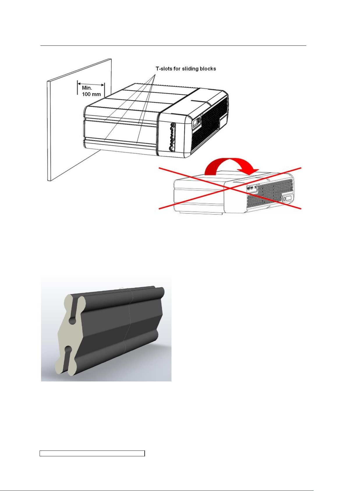
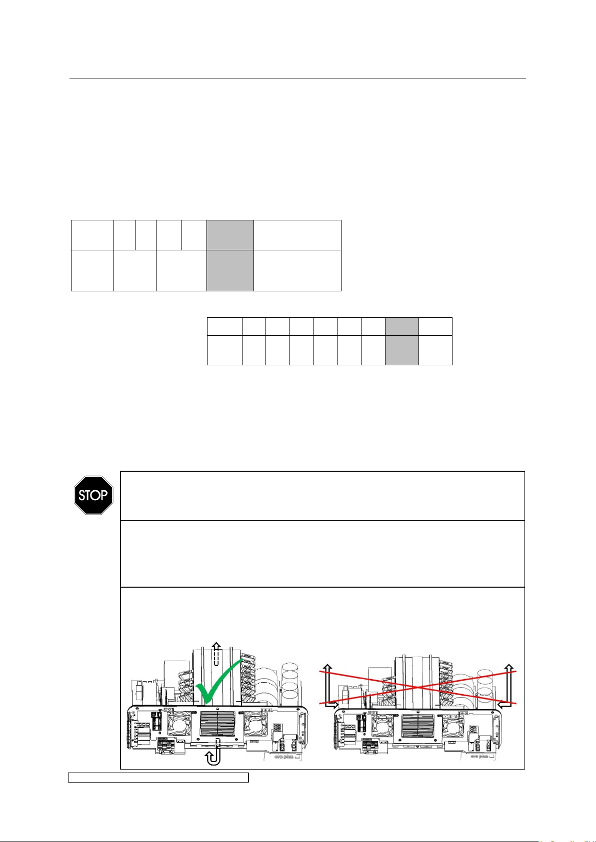
The ELC may only be installed as described in 3.1.1 and in 3.1.2, allowing for at
least the minimum spacing as shown in Fig. 3.
Horizontal mounting upside down is not allowed. All vertical mounting
orientations are possible.
The ELC should not be mounted in the immediate proximity of sensitive electronic
equipment. An appropriate distance must be maintained to scatter field
transformers or other inductors.
The ELC is equipped with built-in fans to ensure forced air cooling. Air ducts and
optional filters must be designed to allow the air flow described in chapter 6. The
ambient temperature must not exceed the values described in chapter 6. The
ambient temperature is measured by the ELC and will be stored within the
internal error memory.
3 Installation
3.1 Mounting of casing
3.1.1 Mounting of single ELC
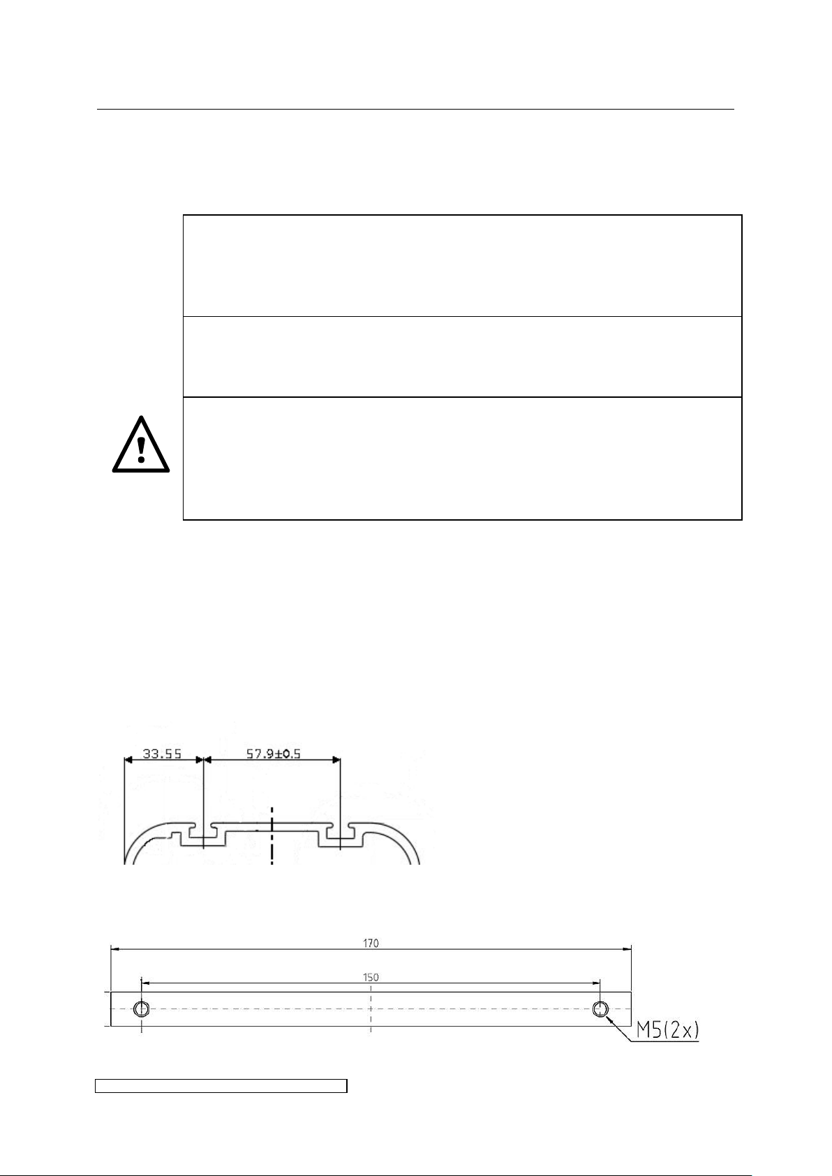
The side surfaces of the housing contain 2 T-slots each. Fig. 1 indicates the relative interspace
of the two T-slots and distance to the outer face of the housing. The T-slots are suitable for
sliding blocks 6mm groove, M5 by Bosch Rexroth, as well as for sliding profiles (see Fig. 2) ,
the latter applicable for X6 and higher power, both available as accessories. Fig. 3 shows the
horizontal mounting orientation including the minimum spacing at the back of the ELC.
Alternatively the ELC may be mounted flush with the rear panel if a cut out for the ventilation
is ensured.
Fig. 1: Position of the T-slots
Fig. 2: Sliding profile
Page 9
3 Installation page 5
ELC X-Series-V1.5-06.18-GB subject to technical alterations
Fig. 3: Mounting of the ELC, horizontal orientation
3.1.2 Mounting in a stack
Up to 12 ELC may be mounted on top of each other. To fasten the ballasts onto each other a
custom-built stacking connector has to be used (available as accessories):
Fig. 4: Stacking connector for stack mounting
Page 10
3 Installation page 6
ELC X-Series-V1.5-06.18-GB subject to technical alterations
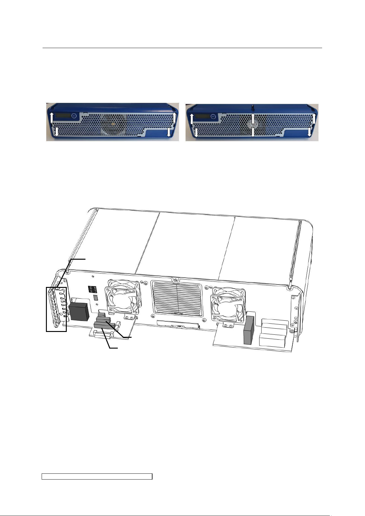
Cable gasket
X100
X600
X2
X1
X3
X805
X806
3.2 Connection
To gain access to the electrical contacts the front hood has to be removed. Loosen the
screwing (according to model 4 or 6 x TX20-screw) and detach the front hood.
The following paragraphs describe the electrical connections.
3.2.1 Connection overview of ballast types X4 – X8
Fig. 5: Overview of electrical connections X4-X8
Page 11
3 Installation page 7
ELC X-Series-V1.5-06.18-GB subject to technical alterations
Cable gasket
Cable
diameter
Connector
designation
Function
Connector
no. of pins
Connector
type eta
ID.:
Cable
length
(gasket to
connector)
Plug
contact
7.5mm
±5%
X3
Bus out
(T-
coupler)
3
9546
120mm
blank
wire or
ferrule
9.3mm ±
5%
X600 (1, 3)
Lamp
output
3
9532
155mm
blank
wire or
ferrule
4.9mm ±
5%
X600 (2)
PE
5.2mm ±
5%
X806
Control
7
9535
130mm
ferrule
7.5mm ±
5%
X1
Bus in
4
9545
120mm
blank
wire or
ferrule
6.7mm ±
5%
X805
Control
11
9536
130mm
ferrule
7.5mm ±
5%
X2
Bus out
4
9545
120mm
blank
wire or
ferrule
12.2mm ±
5%
X100
Mains
input (2 x
Phase, 2 x
PE)
4
9531
490mm
blank
wire or
ferrule
3.2.2 Profile of the cable gasket X4 – X8
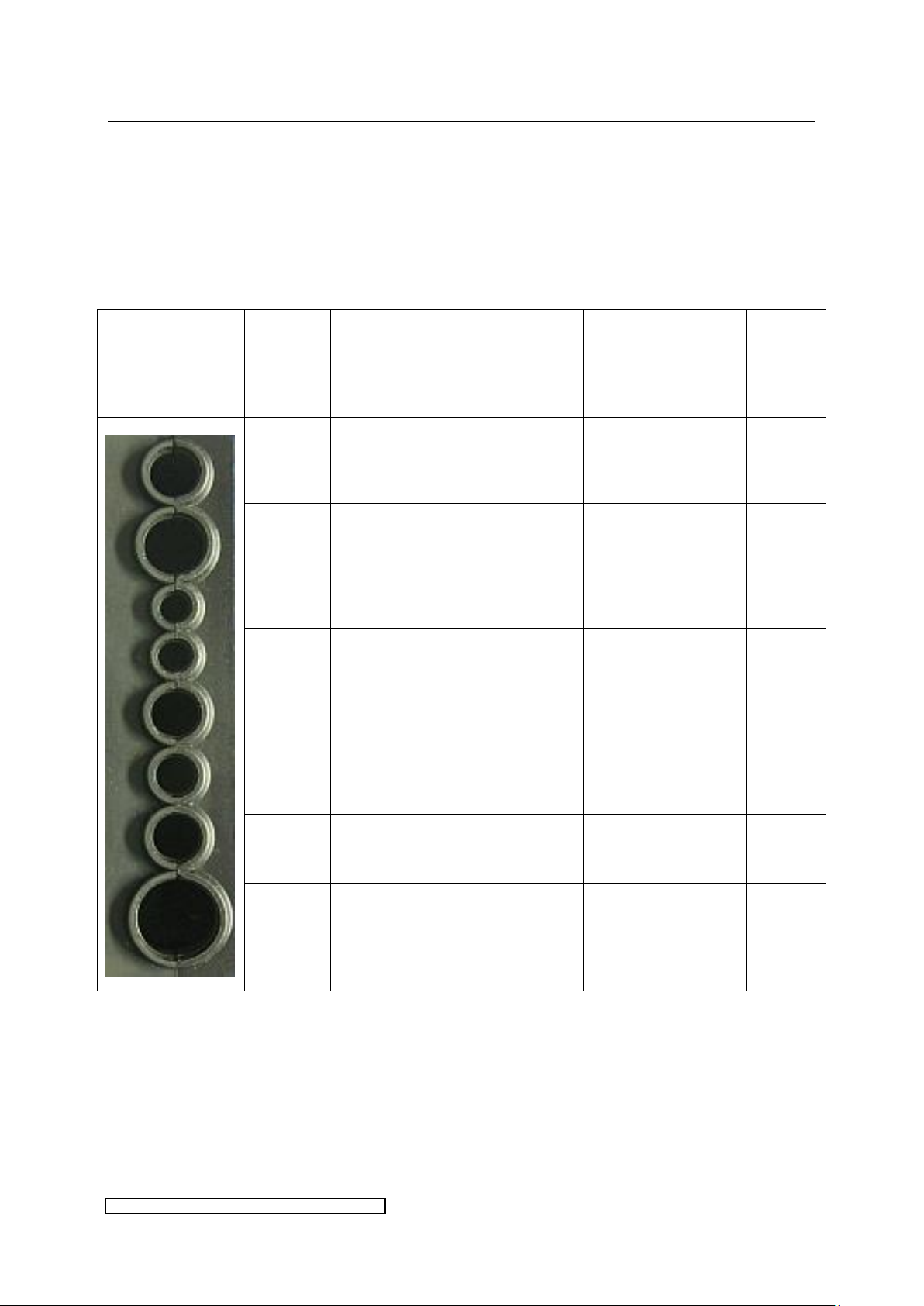
The IP protection level given in chapter 6 is only guaranteed if every cable’s lead-in is
completely sealed.
For this purpose the following preconditions have to be fulfilled:
Use cables of the nominal diameters given in Table 1.
Table 1: Cable connection parameters X4-X8
Page 12
3 Installation page 8
ELC X-Series-V1.5-06.18-GB subject to technical alterations
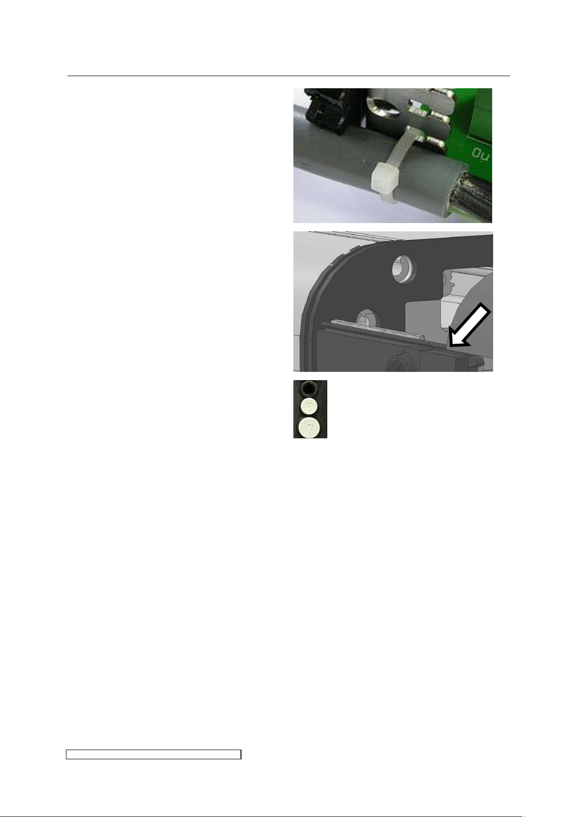
Place the cables into the rubber
surrounds and fix them onto the clamp
with cable straps:
Slide the front hood onto the sealing lip
and pay attention to a tight connection of
the front hood.
If the control concept requires fewer
control and bus cables the holes of the
rubber surround have to be sealed with
blank plugs (available as accessories):
Page 13
3 Installation page 9
ELC X-Series-V1.5-06.18-GB subject to technical alterations
The lamp feeder cable shielding must be connected to the ELC at the designated
shield clamp, see paragraph 3.2.9.
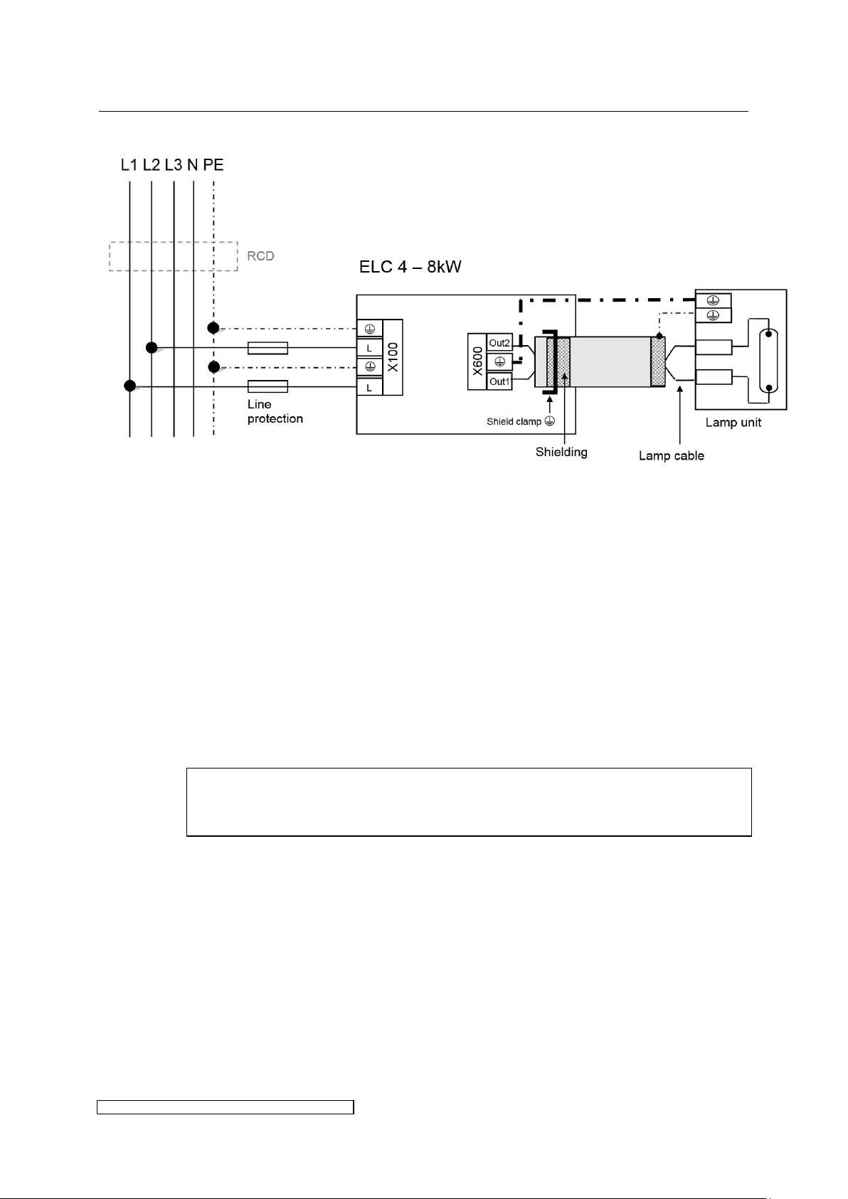
3.2.3 Overview power connections X4 – X8
Fig. 6: Power connection X4-X8
Fig. 6 shows the electrical wiring. Please consider the following aspects:
Voltage balancing: on installing several ELCs the ballasts have to be equally distributed on all
phases (e.g. 1st ballast L1/L2, 2nd ballast L2/L3, 3rd ballast L3/L1 etc.).
Protective conductors: to ground the ballast it is strongly recommended to connect to X100 at
least one PE-line with a cross section of 10mm² or two PE-lines with nominal cross section of
the mains supply lines.
Cut-Out and loop impedance: The installation of an automatic cut-out is required for line
protection. It is necessary to check the loop impedance afterwards.
Using an RCD: if a RCD is required we recommend a RCD type B. When using a RCD consider
the leakage current given in chapter 6.
Shielding:
If desired, the shielding can also be connected to the lamp unit.
Page 14
3 Installation page 10
ELC X-Series-V1.5-06.18-GB subject to technical alterations
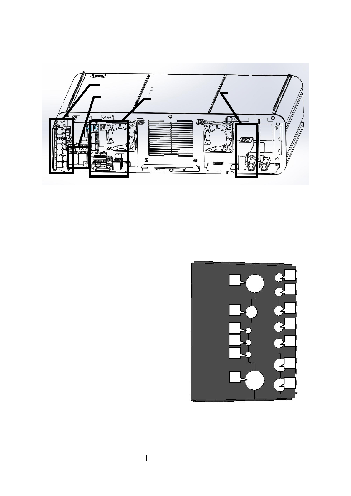
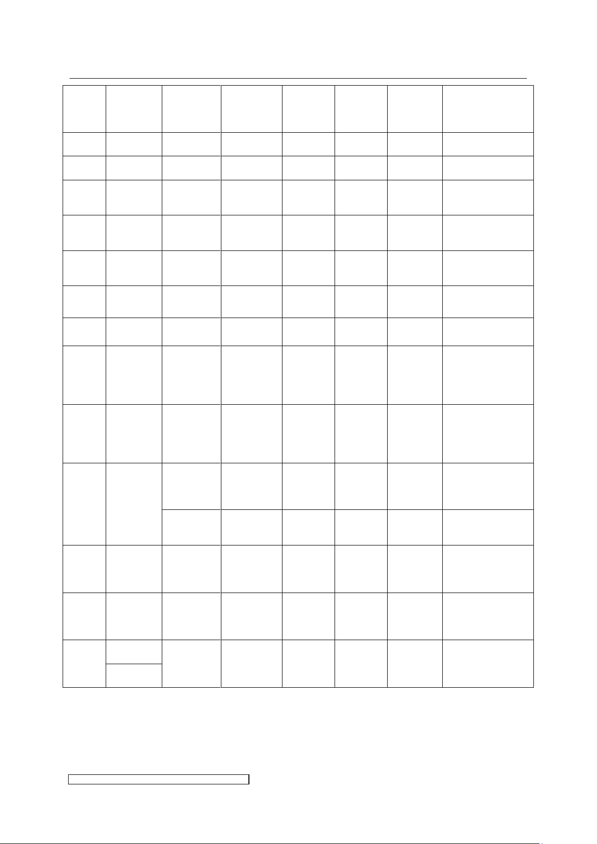
Use cables of the nominal diameters given
in Table 2 on page 11. For the mapping to
the lead-ins in the cable gasket see Fig. 8.
The gasket provides alternative lead-ins for
the use of several cable types.
Fig. 8: Profile of the cable gasket X12-X36
Mains connection
Control connections
Lamp
connection
Cable gasket
4
3
2
1
5
6 7 8
9
10
11
12
13
3.2.4 Connection overview of ballast types X12 – X36
Fig. 7: Overview of electrical connections X12-X36
3.2.5 Overview profile of the cable gasket X12 – X36
The IP protection level given in chapter 6 is only guaranteed if every cable’s lead-in is
completely sealed.
For this purpose the following preconditions have to be fulfilled:
Page 15
3 Installation page 11
ELC X-Series-V1.5-06.18-GB subject to technical alterations
Position
(see
Fig. 8)
Cable
diameter
Connector
designation
Function
Connector
no. of pins
Connector
type eta
ID.:
Cable
length
(gasket to
connector)
Plug contact
1
6.8mm ±
5%
X806
Control
7
9535
130mm
ferrule, stripping
length 7mm
2
6.8mm ±
5%
X805
Control
11
9536
130mm
ferrule, stripping
length 7mm
3
7.5mm
±5%
X3
Bus out
(T-coupler)
3
9546
120mm
blank wire or
ferrule, stripping
length 9mm
4
7.5mm ±
5%
X1
Bus in
4
9545
120mm
blank wire or
ferrule, stripping
length 9mm
5
7.5mm ±
5%
X2
Bus out
4
9545
120mm
blank wire or
ferrule, stripping
length 9mm
6
9.8mm ±
5%
X806
Control
(alternative)
7
9535
130mm
ferrule, stripping
length 7mm
7
9.8mm ±
5%
X805
Control
(alternative)
11
9536
130mm
ferrule, stripping
length 7mm
8
13.5mm ±
5%
X600 (1, 3)
Lamp
output
2 - 155mm
blank wire or
ferrule stripping
length 15mm,
direct connection
on board
9
9.3mm ±
5%
X600 (1, 3)
Lamp
output
(alternative)
2 - 155mm
blank wire or
ferrule stripping
length 15mm,
direct connection
on board
10
5.4mm ±
5%
X600 (2)
PE 1 -
155mm
Blade receptacle
6.3mm, direct
connection on
board
X100 (1)
Mains input
PE
(alternativ)
1
9531
490mm
blank wire or
ferrule, stripping
length 18mm
11
5.4mm ±
5%
X100 (2)
Mains input
phase
(alternativ)
1
(9531)
490mm
blank wire or
ferrule, stripping
length 18mm
12
5.4mm ±
5%
X100 (4)
Mains input
phase
(alternativ)
1
(9531)
490mm
blank wire or
ferrule, stripping
length 18mm
13*
12.0mm ±
5%
X100
Mains input
(2 x phase, 2
x PE)
4
9531
490mm
blank wire or
ferrule, stripping
length 18mm
14.6mm ±
5%
Table 2: Cable connection parameters X12-X36
Page 16
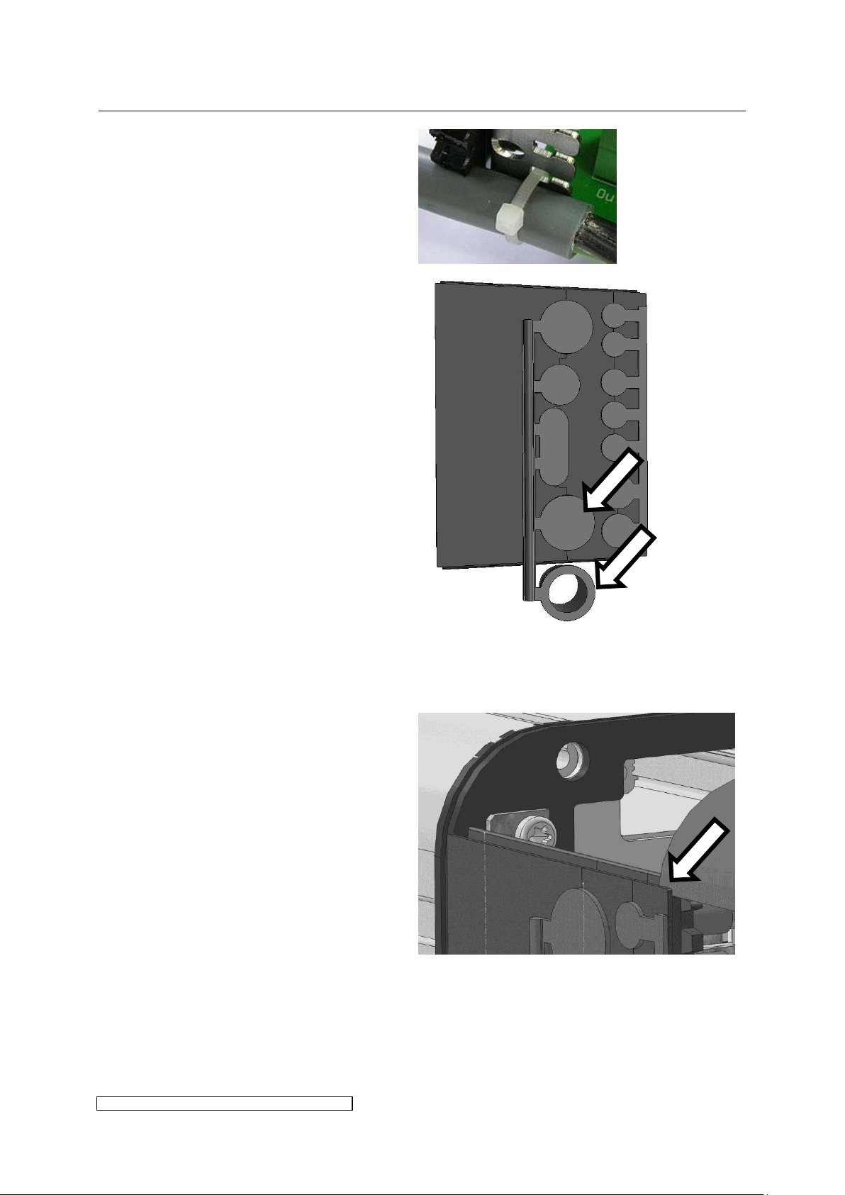
3 Installation page 12
ELC X-Series-V1.5-06.18-GB subject to technical alterations
Place the cables into the rubber
surrounds and fix them onto the clamp
with cable straps:
On delivery the lead-ins are sealed with
blank plugs (see Fig. 9). These can be
removed as required.
Note to the lead-in of mains supply (cf.
position 13 in Fig. 8 and Table 2):
When using mains supply cables of
maximally possible diameter the
according blank plug of the blank plug
line has to be removed.
In case of smaller diameter use the
sealing ring of Fig. 9 and put the cable
through it.
Fig. 9: Blank plug line with sealing ring for ELC
X12-X36
Slide in the front hood centrically into
the sealing lips and pay attention to a
tight connection of the front hood.
Page 17
3 Installation page 13
ELC X-Series-V1.5-06.18-GB subject to technical alterations
The lamp feeder cable shielding must be connected to the ELC at the designated
shield clamp, see paragraph 3.2.9.
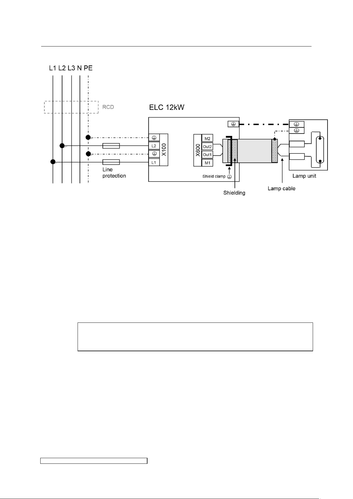
3.2.6 Overview power connections X12
Fig. 10: Power connection X12
Please consider the following aspects:
Voltage balancing: on installing several ELCs the ballasts have to be equally distributed on all
phases (e.g. 1st ballast L1/L2, 2nd ballast L2/L3, 3rd ballast L3/L1 etc.).
Protective conductors: to ground the ballast it is strongly recommended to connect to X100 at
least one PE-line with a cross section of 10mm² or two PE-lines with nominal cross section of
the mains supply lines.
Cut-Out and loop impedance: The installation of an automatic cut-out is required for line
protection. It is necessary to check the loop impedance afterwards.
Using a RCD: if a RCD is required we recommend a RCD type B. When using a RCD consider
the leakage current given in chapter 6.
Shielding:
If desired, the shielding can also be connected to the lamp unit.
Page 18
3 Installation page 14
ELC X-Series-V1.5-06.18-GB subject to technical alterations
The lamp feeder cable shielding must be connected to the ELC at the designated
shield clamp, see paragraph 3.2.9.
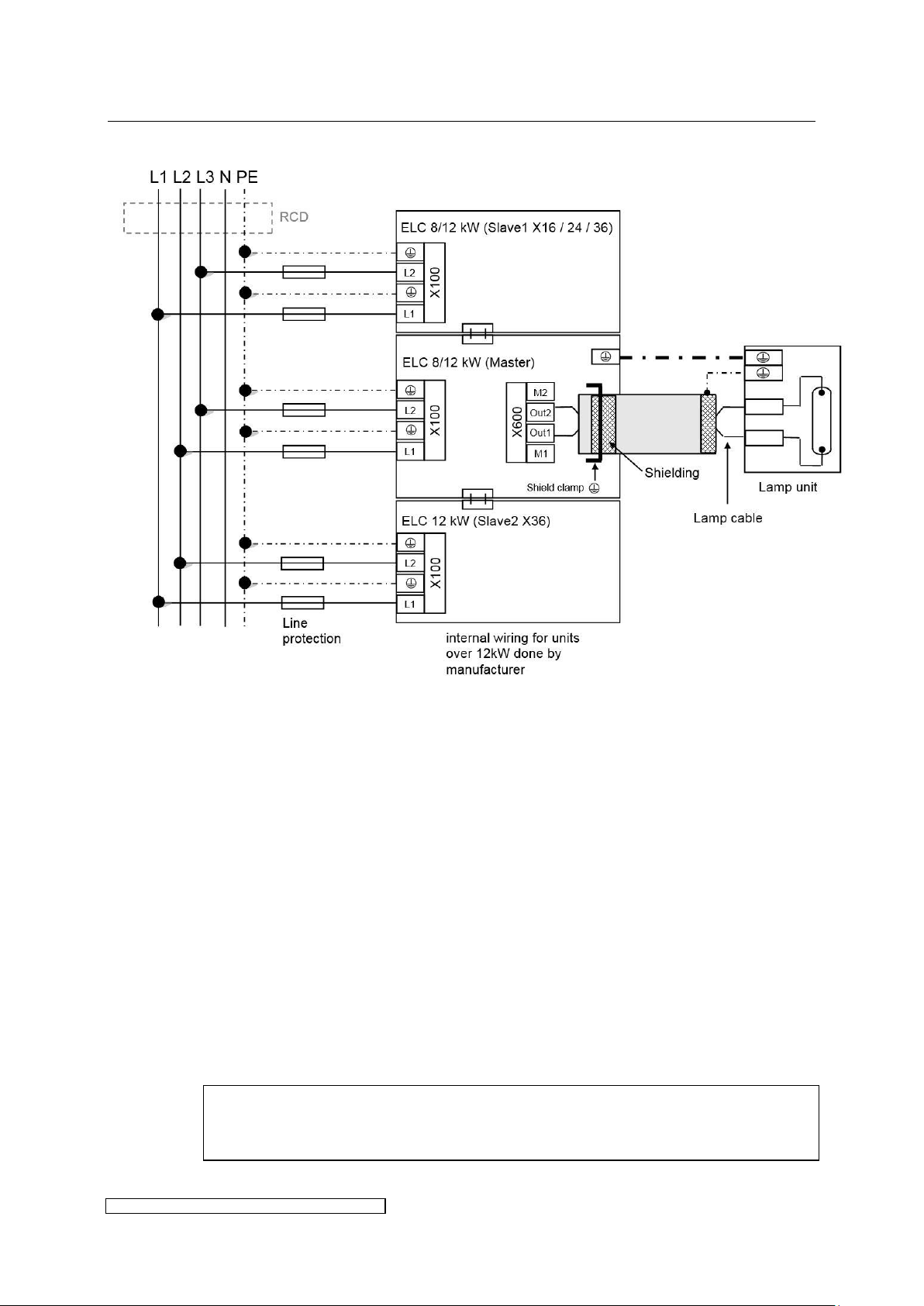
3.2.7 Overview power connections X16 – X36
Fig. 11: Power connections X16 – X36
Please consider the following aspects:
Connecting the lines: The Slave module has only to be connected to power supply including
PE on X100. The Master module has to be connected to power supply and PE on X100, and
additionally to all bus-, control- and lamp cables.
Voltage balancing: on installing several ELCs the ballasts have to be equally distributed on all
phases (e.g. 1st ballast L1/L2, 2nd ballast L2/L3, 3rd ballast L3/L1 etc.).
Protective conductors: to ground the ballast it is strongly recommended to connect to X100 at
least one PE-line with a cross section of 10mm² or two PE-lines with nominal cross section of
the mains supply lines.
Cut-Out and loop impedance: The installation of an automatic cut-out is required for line
protection. It is necessary to check the loop impedance afterwards.
Using an RCD: if a RCD is required we recommend a RCD type B. When using a RCD consider
the leakage current given in chapter 6.
Shielding:
If desired, the shielding can also be connected to the lamp unit.
Page 19
3 Installation page 15
ELC X-Series-V1.5-06.18-GB subject to technical alterations
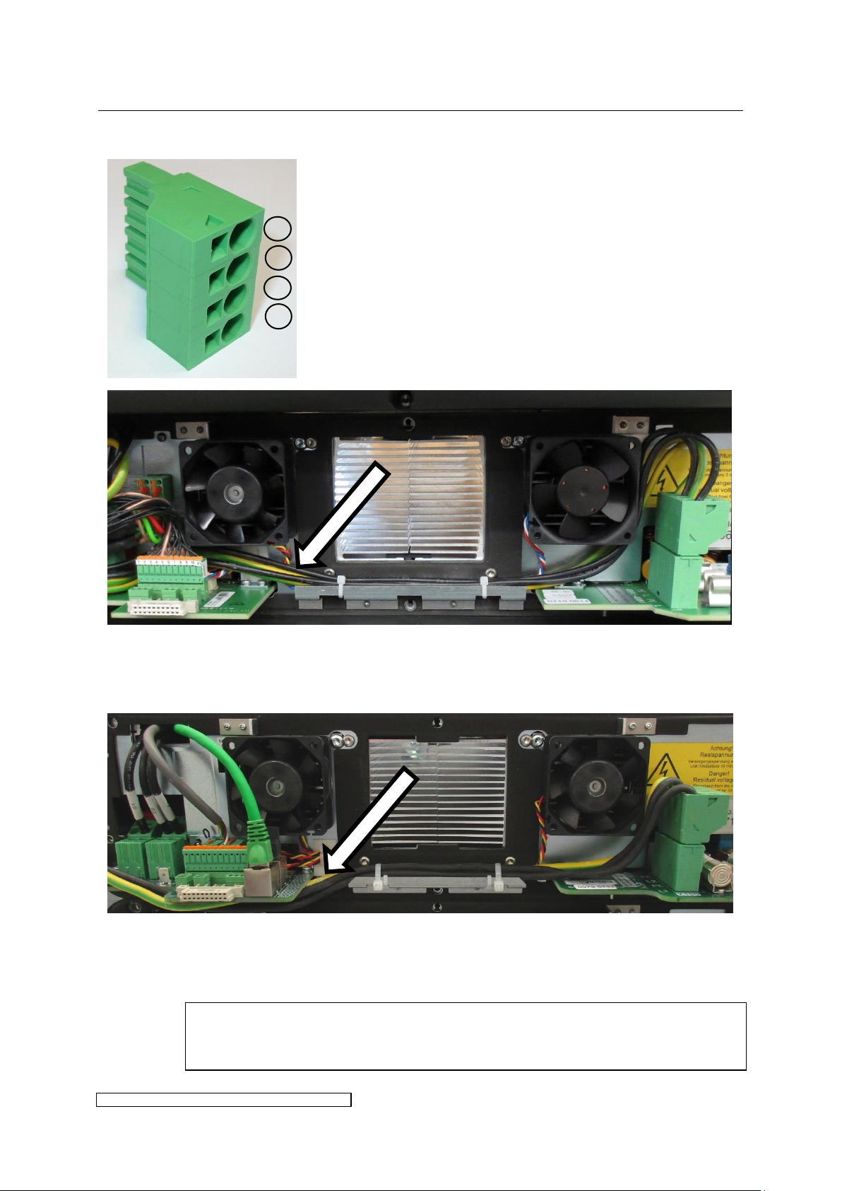
X4-X8: Fix the mains connection cables within the cable holder beneath the heat sink with
cable straps. The cables have to be laid behind the control connectors to reach the cable
gasket.
X12-X36: Fix the mains connection cables within the cable holder with cable straps. The
cables have to be laid beneath the board to reach the cable gasket.
Pay attention not to pinch the cables when closing the front hood.
L1
PE
L2
PE
3.2.8 X100: Mains connection
Page 20
3 Installation page 16
ELC X-Series-V1.5-06.18-GB subject to technical alterations
The lamp feeder cable must correspond with the cable parameters described in
chapter 6.
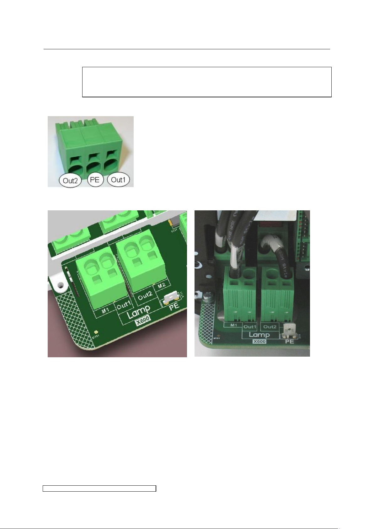
X4-X8 use a plug for the connection:
PE may be collected of pin 2 of the
connector in order to earth the lamp
housing. If the lamp-housing is earthed
otherwise, the pin has to be left open.
X12-X36 lamp feeder cables are connected directly on the board:
Schematic of lamp connection X12-36
Example of X24 master board (delivery
state)
Connector order:
M1 (reserved for internal wiring) - Out1 – Out 2 - M2 (reserved for internal wiring)
PE
3.2.9 X600: Connecting the lamp feeder cable
Page 21
3 Installation page 17
ELC X-Series-V1.5-06.18-GB subject to technical alterations
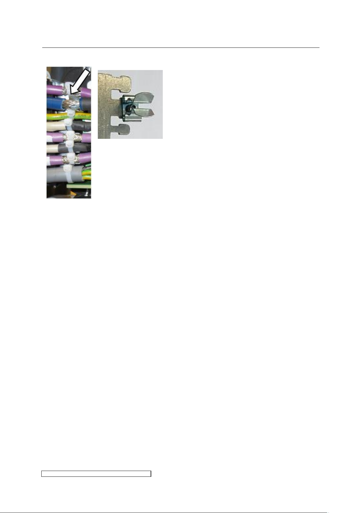
Laying in cable gasket:
The shield clamp is provided for the shield
of the lamp feeder cable. For this cable the
cable strap is not necessary.
The lamp feeder cable between the switch cabinet and lamp assembly must be laid in a
protected way. For the correct installation of the lamp assembly and lamp please observe
the corresponding manufacturer’s instructions.
Page 22
3 Installation page 18
ELC X-Series-V1.5-06.18-GB subject to technical alterations
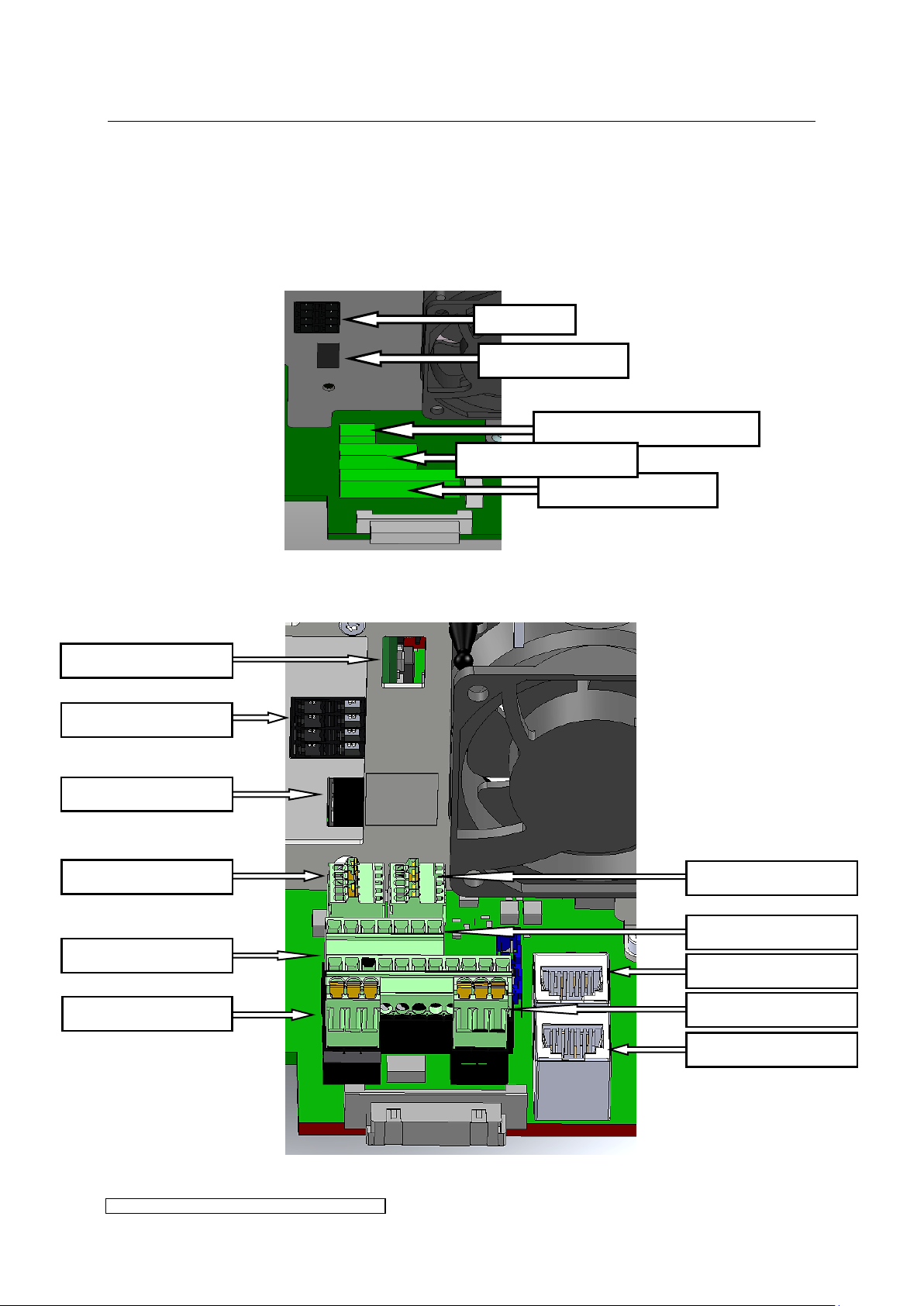
X300: Service USB
X1/X2: BUS
X122: int. connection
X604: int. connection
X123: int. connection
X605: int. connection
X805: Control cable
X102: not in use
X806: Control cable
X3: BUS T-coupler
X104: Service PFC
X3: BUS T-coupler
X808: Service interface
X805: Control cable
X806: Control cable
3.2.10 Overview of control and bus connections
The control cables are connected by means of the plug connections available as accessories.
All control circuits must be earthed upon installation.
The connector positions are shown in Fig. 12 or Fig. 13 and will be explained in the following
tables.
Fig. 12: Control and bus connections X4-X8
Fig. 13: Control and bus connections X12-X24
Page 23
3 Installation page 19
ELC X-Series-V1.5-06.18-GB subject to technical alterations
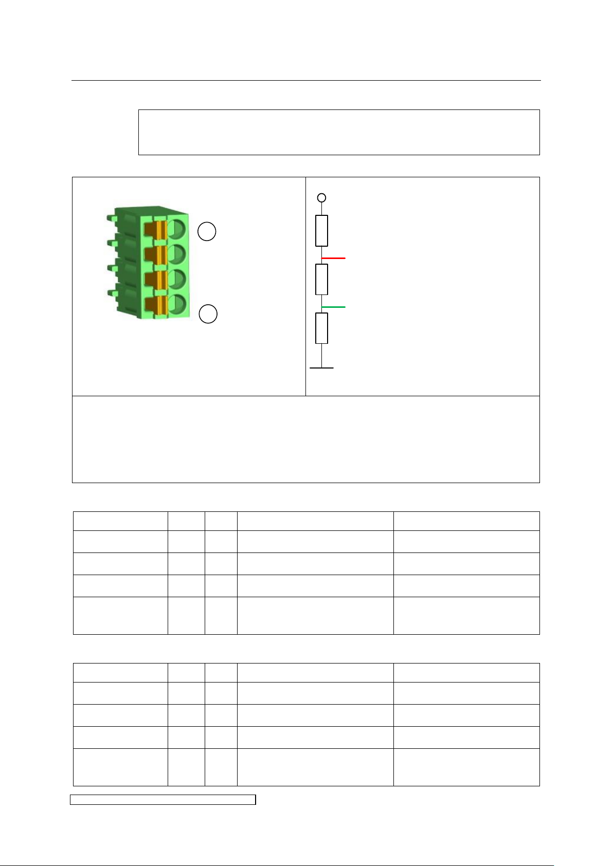
To ensure secure data transmission the use of a BUS-specific cable is
recommended.
Connector pin assignment:
Fig. 14: BUS-termination
The shield has to be put on Pin 1 = BUS GND. Insulate with shrunk-on sleeve.
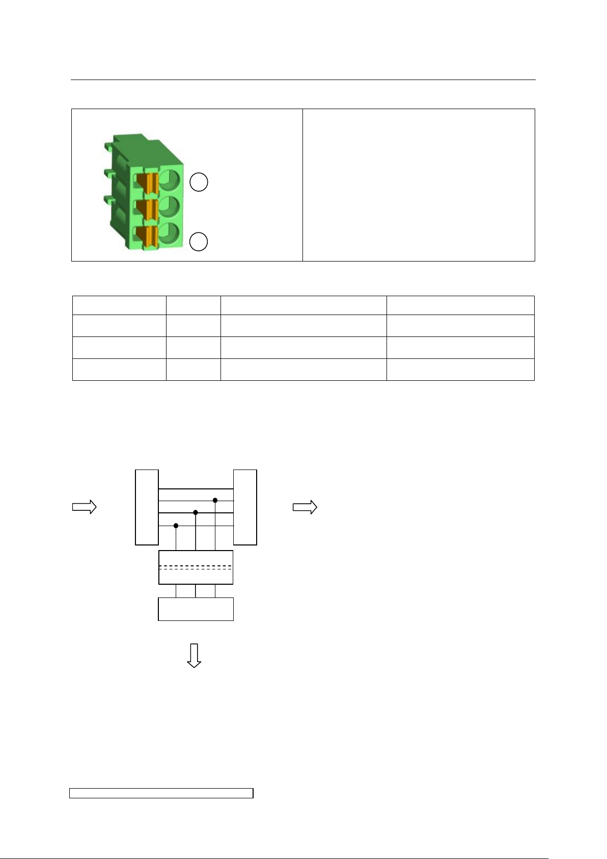
The contacts of X1 and X2 are internally connected.
The RS485 BUS has to be terminated at the end of the BUS line according to PROFIBUS-Norm
IEC 61158 (also see Fig. 14). On the last ballast one of the connectors X1 or X2 will be left
open and can be used for the termination (available as accessories).
Designation
X1
X2
Description
technical
BUS GND
X1.1
X2.1
GND insulated for BUS
Shield connection BUS
BUS A
X1.2
X2.2
Data line BUS A
Bus signal A
BUS B
X1.3
X2.3
Data line BUS B
Bus signal B
BUS VCC
X1.4
X2.4
external supply voltage 5V
insulated for BUS
+5V DC insulated, output for
terminator only
Designation
X1
X2
Description
technical
BUS GND
X1.1
X2.1
GND insulated for MODBUS
Shield connection MODBUS
BUS A
X1.2
X2.2
Data line A
Inverting In-/Output
BUS B
X1.3
X2.3
Data line B
None inverting In-/Output
BUS VCC
X1.4
X2.4
external supply voltage 5V
insulated for Bus-termination
+5V DC insulated, output for
terminator only
5V
A
B
390 Ω
390 Ω
220 Ω
1
4
3.2.11 X1 / X2: BUS connections
Pin assignment X1 / X2 for BUS:
Pin assignment X1 / X2 for MODBUS:
Page 24
3 Installation page 20
ELC X-Series-V1.5-06.18-GB subject to technical alterations
Connector pin assignment:
The shield has to be put on Pin 1 = BUS GND.
Insulate with shrunk-on sleeve.
Designation
Number
Description
technical
BUS GND
X3.1
GND insulated for BUS
Shield connection BUS
BUS A
X3.2
Data line BUS A
Bus signal A
BUS B
X3.3
Data line BUS B
Bus signal B
1.4
1.3
1.2
1.1
2.4
2.3
2.2
2.1
3.1 3.2 3.3
X3
X1
X2
galvanic isolation
T-coupler
1
3
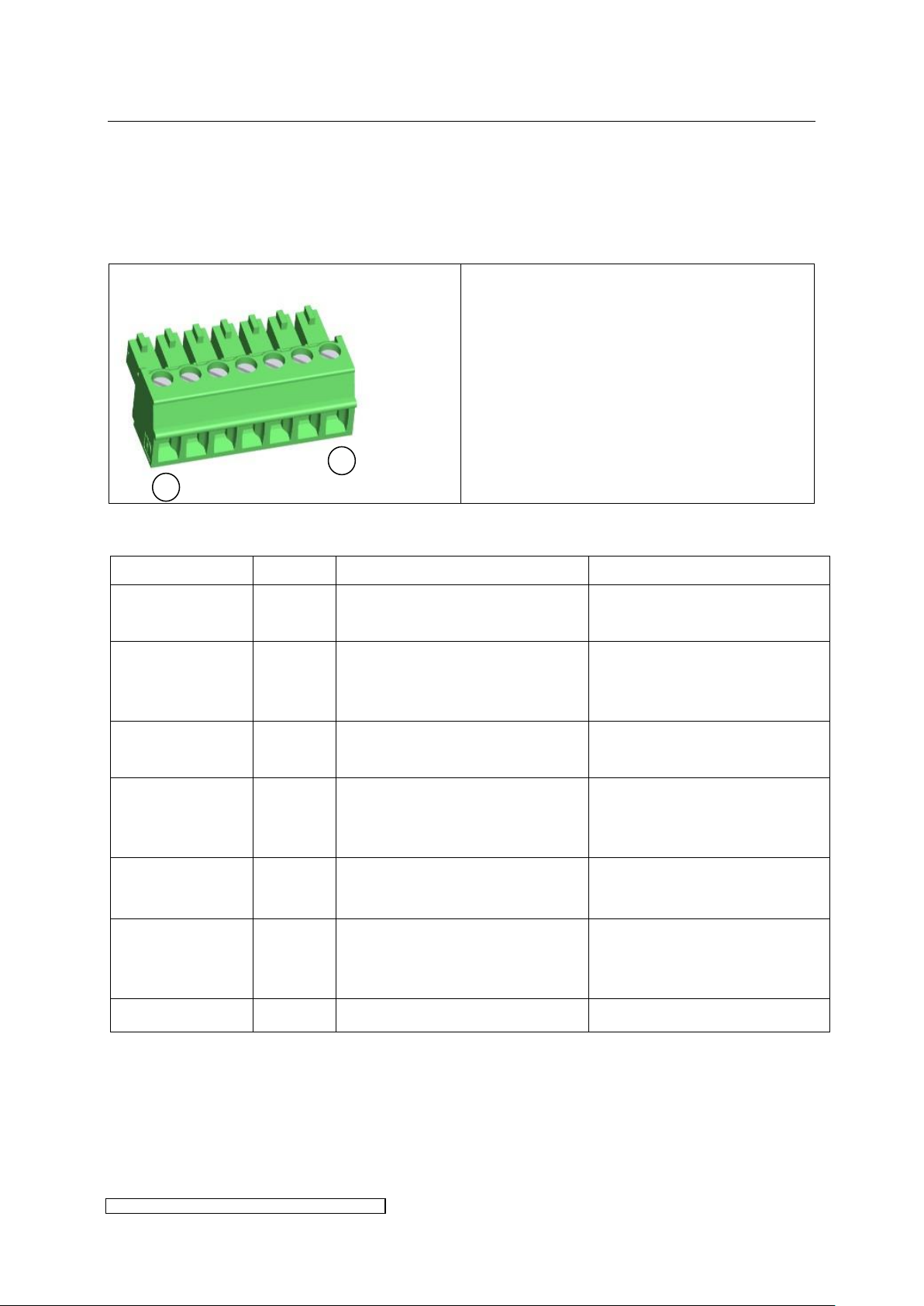
3.2.12 X3: BUS T-coupler
Pin assignment X3:
The T-coupler connection may be used as a BUS repeater. Via the T-coupler (see Fig. 15) the
BUS-data lines A and B as well as their reference ground may be applied (galvanically
insulated) to another slave device. The T-coupler already contains a termination according to
Fig. 14. Solely a bitrate of 500kbit is applicable. If the T-coupler connection is not required X3
may be left open.
Fig. 15: Schematic of the T-coupler connection
X3 is not active in MODBUS control mode.
Page 25
3 Installation page 21
ELC X-Series-V1.5-06.18-GB subject to technical alterations
Connector pin assignment:
Connection torque:
min. 0.22 Nm
max. 0.25 Nm
Designation
Number
Description
technical
Interconnection
OUT
X806.1
Continuous contact, connected
to X805.1
max. 1A, 24V DC
Safety Relay IN
X806.2
Control signal input safety relay
+24V DC
Control signal (+24V DC ± 10%
/ 35mA) for the safety relay in
reference to X806.7 (GND)
Init Signal IN
X806.3
Input initialisation signal for
safety shutdown +24Vext.
24V DC ± 10% external supply
in reference to X806.7 (GND)
Shield
X806.4
Continuous contact, connected
to X805.4, usable for shield of
the control cable
max. 1A, 24V
24V_OUT
X806.5
Output 24V DC,
connected to X805.5
24V DC ± 10%,
max. 1.8A
24V_USV*
X806.6
Short-time buffer voltage after
emergency shutdown/switchoff
Capacitance 47mF +/-20% 24V
+/-10%
24V_GND
X806.7
Common (GND)
GND
1
7
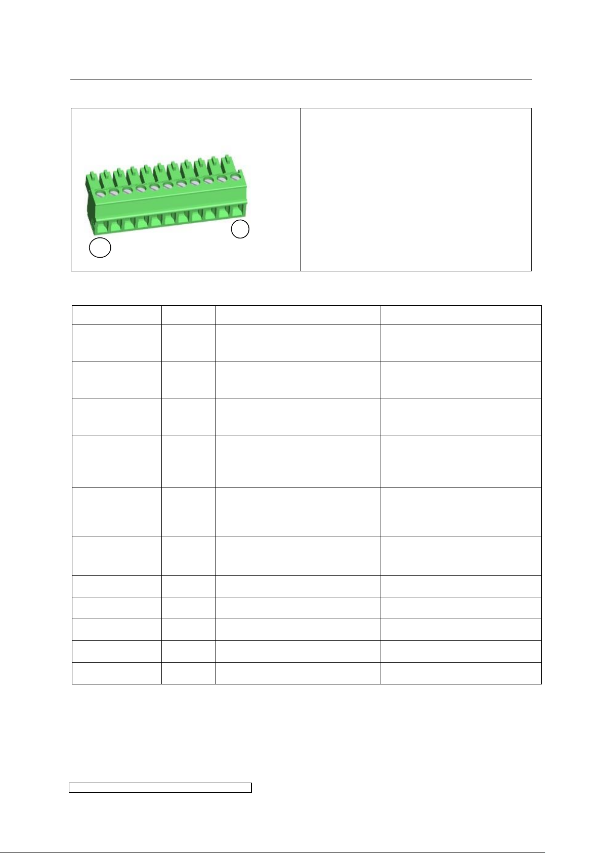
3.2.13 X805 and X806: Control cables
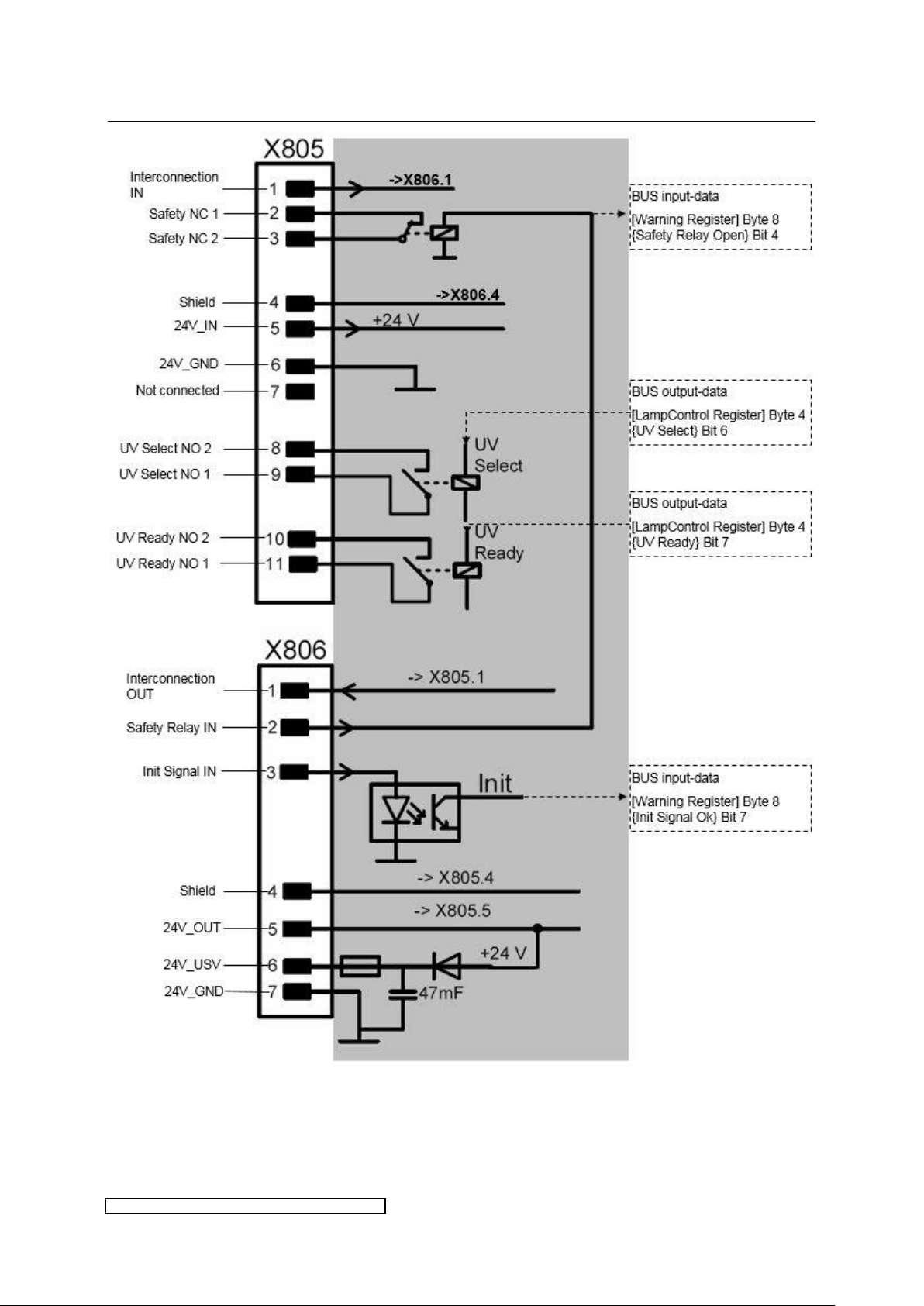
Fig. 16 on page 24 shows the interconnection of X805 and X806. Comments on the wiring are
given in the following tables.
X806:
Pin assignment X806:
* 24V_USV available for certain ELC-types only
Page 26
3 Installation page 22
ELC X-Series-V1.5-06.18-GB subject to technical alterations
Connector pin assignment:
Connection torque:
min. 0.22 Nm
max. 0.25 Nm
Designation
Number
Description
technical
Interconnection
IN
X805.1
Continuous contact, connected
to X806.1
max. 1A, 24V
Safety NC 1
X805.2
Feedback contact 1 safety relay
Normally closed contact
24V / 1A
Safety NC 2
X805.3
Feedback contact 2 safety relay
Normally closed contact
24V / 1A
Shield
X805.4
Continuous contact, connected
to X806.4, usable for shield of
the control cable
max. 1A, 24V
24V_IN
X805.5
Connection for external supply
voltage, connected to X806.5
24V DC ± 10%, current
consumption of the ELC control
circuitry see chapter 6
24V_GND
X805.6
Common (GND),
connected to X806.7
GND
not connected
X805.7
Not connected
UV Select NO 2
X805.8
Feedback contact 2 UV-select
Normally open contact 24V/1A
UV Select NO 1
X805.9
Feedback contact 1 UV-select
Normally open contact 24V/1A
UV Ready NO 2
X805.10
Feedback contact 2 UV-ready
Normally open contact 24V/1A
UV Ready NO 1
X805.11
Feedback contact 1 UV-ready
Normally open contact 24V/1A
1
11
X805:
PIN-assignment X805:
Page 27
3 Installation page 23
ELC X-Series-V1.5-06.18-GB subject to technical alterations
ByteNr.
0 1 2 3 4
5
Name
[Power
Set
Value]
[Installed
Lamp
Power]
[Lamp
Control]
[Reserved]
Bit 7 6 5 4 3 2 1 0
Name
UV
Ready
UV
Select
n/a
Extended
Range
n/a
n/a
Clear
Error
Start
Lamp
NB: X805.8 to X805.11: the contacts which are normally open (cf. Fig. 16) will be closed as soon
as the corresponding bit is set in Register [Lamp Control] of the BUS output-data (cf.
paragraph 3.4). Bit 6 closes UV Select, Bit 7 closes UV Ready. Use if required, not essential for
operating the ELC.
BUS-output-data (Master → ELC)
↓
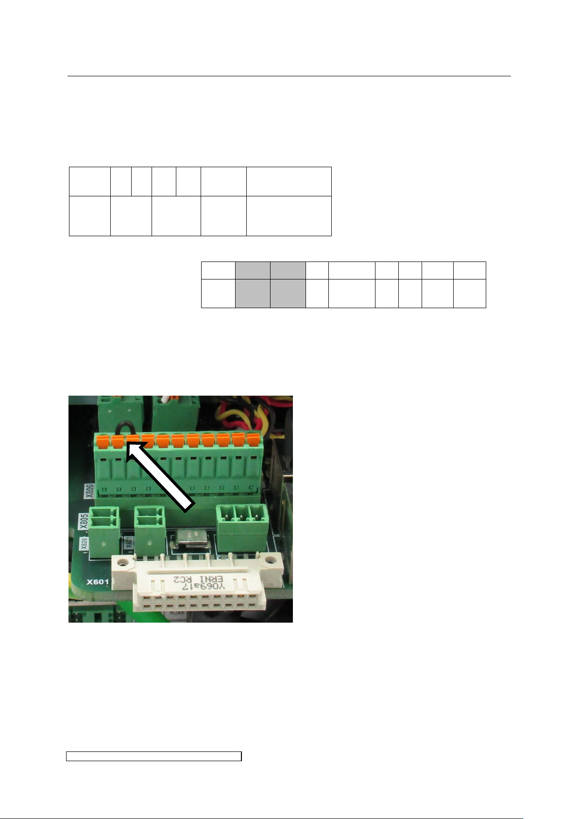
Pin assignment for X16-X36:
The ELC master has to be connected according to the preceding table. Slave ballasts require
a bridge between pin 2 and pin 3:
3.2.14 X808/X300: Service interface
For use by the manufacturer.
Page 28
3 Installation page 24
ELC X-Series-V1.5-06.18-GB subject to technical alterations
Fig. 16: Circuit diagram of the control connectors X805 and X806
Page 29

3 Installation page 25
ELC X-Series-V1.5-06.18-GB subject to technical alterations
3.3 Comments on the safety functions of the ELC
In addition to the safety functions included in all previous ELC-types such as earth fault
detection, temperature limit, safe operation in both short-circuit and open circuit at the lamp
output, the ELC X-Series includes an additional function in the form of the definite lamp
shutdown. To date this function was assured by external components, e.g. a power contactor
cutting off the mains supply voltage of the ELC.
The definite lamp shutdown is implemented using two independent circuits which can be
regarded as redundant functions in terms of the safety assessment of the installation. The first
lamp shutdown function contains a safety relay which cuts the voltage-output of the ELC via
hardware. This safety function can be monitored by appropriate processing of the feedback
contacts „Safety NC1 + Safety NC2“.
A second safety shutdown may be realized with the input „Init Signal IN“. Here the cut off of
the output voltage is based on software.
The status of both safety circuits may be read out by BUS. However they can not be deactivated
via software. It is therefore necessary to apply 24V to both inputs „Safety Relay IN“ and „Init
Signal IN“. If the safety fuctions are not used it is possible to set wire jumpers between
„24V_Out“ (X806.5) and „Safety Relay IN“ (X806.2) and „Init Signal IN“ (X806.3).
Fig. 16 on page 24 shows an overview of the circuits.
3.3.1 Safety relay
To set the ELC ready for operation, the safety relay K1 has to be activated by applying +24V to
pin X806.2.
As long as the safety relay is not activated, lamp operation is not possible! There are two
feedback paths:
a normally closed relay contact. It may be tapped on pins X805.2 and X805.3.
the [Warning Register] of the BUS-input-data (see below and paragraph 5.2: Bit 4
{Safety Relay Open})
If the safety relay is deactivated during lamp operation, lamp operation will be shut down. After
reactivating the safety relay, the lamp has to be restarted.
3.3.2 Initialisation signal
Furthermore lamp operation will not be allowed unless +24V are applied to pin X806.3. This is
an additional monitoring function for the safe operation of the installation. The status of pin
X806.3 is visualized in the [Warning Register] of the BUS-input-data (see below and paragraph
5.2: Bit 7 {Init Signal Ok}).
If the initialisation signal is deactivated during lamp operation, lamp operation will be shut
down. After re-applying the initialisation signal, the lamp has to be restarted.
Page 30
3 Installation page 26
ELC X-Series-V1.5-06.18-GB subject to technical alterations
ByteNo.
0 1 2 3 4 5 6 7 8 9 10
11
12
13
14
15
Name
[ELC
Serial
Number]
[Software
Version]
[ELC
Nominal
Power]
[Error
Register]
[Warning
Register]
[Lamp
Status]
[Actual
Power]
[Actual
Voltage]
[Actual
Current]
[Reserved]
ByteNo.
0 1 2 3 4
5
Name
[Power
Set
Value]
[Installed
Lamp
Power]
[Lamp
Control]
[Reserved]
Modbus
Address
0x100
0x101
0x102
0x103
0x104
0x105
0x106
0x107
ByteNr.
0 1 2 3 4 5 6 7 8 9 10
11
12
13
14
15
Name
[ELC
Serial
Number]
[Software
Version]
[ELC
Nominal
Power]
[Error
Register]
[Warning
Register]
[Lamp
Status]
[Actual
Power]
[Actual
Voltage]
[Actual
Current]
[Reserved]
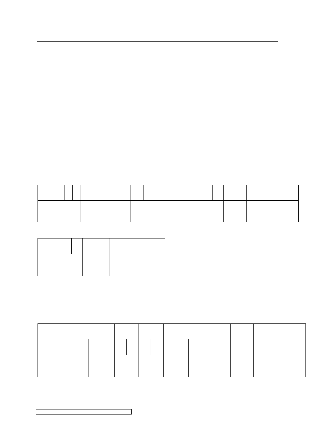
3.4 Configuration
Communication between ELC and installation control is carried out via PROFIBUS DPV0 or
MODBUS RTU. The ELC represents a non-modular DPV0-Slave, the installation control
functions as the Master.
For configuration, control and monitoring of the ELC 16 input registers (Master receiving data
from ELC) were implemented, as well as 6 output registers (Master sending data to ELC). For
registers overlapping more than one byte, the byte order was determined according to ”BigEndian“.
The ELC software is capable of supporting a baud rate according to chapter 6.
The necessary adjustments during the installing of the ELC will be explained in this paragraph,
the adjustments for lamp operation will follow in chapter 4.
The following registers are available:
BUS-Register:
BUS-input-data (ELC → Master)
BUS-output-data (Master → ELC)
MODBUS-Register:
FIELDBUS-input-data (ELC → Master)
Page 31
3 Installation page 27
ELC X-Series-V1.5-06.18-GB subject to technical alterations
Modbus
Address
0x100
0x101
0x102
Byte-Nr.
0 1 2 3 4
5
Name
[Power
Set
Value]
[Installed
Lamp
Power]
[Lamp
Control]
[Special
Function]
FIELDBUS-output-data (Master → ELC)
Additional communication parameters for MODBUS:
The supported function codes are “Write Single Register” (0x06), “Write Multiple Register”
(0x10) and “Read Holding Register” (0x03). The Input and Output data will start at address
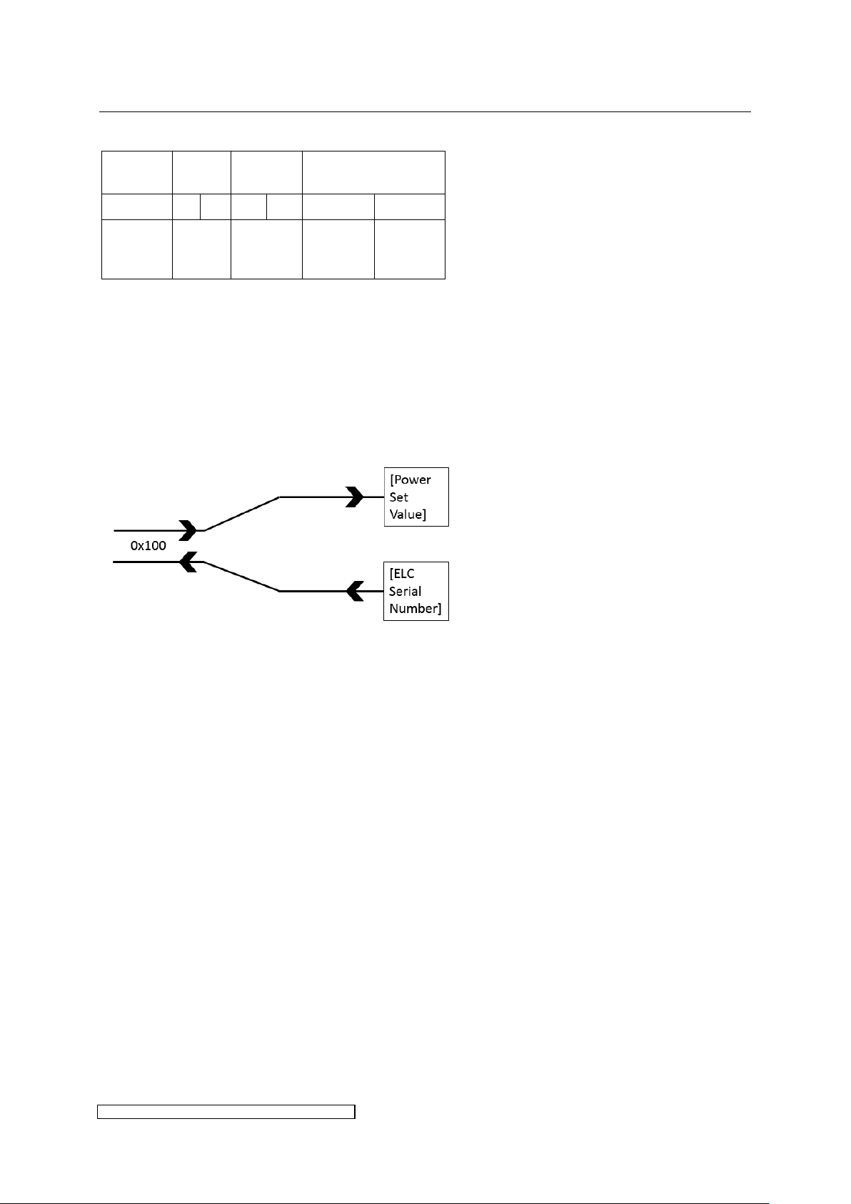
100hex. The addresses 100hex to 102hex differentiate between read or write access, so one
address accesses different registers. Example address 100hex:
Fig. 17: Unequal register access in read and write mode
Attached two trace examples of a transmission (Trace is all HEX):
Read registers of all input registers
Control to X6 --> "0x02, 0x03, 0x01, 0x00, 0x00, 0x08, 0x45, 0xc3"
X6 to Control --> "0x02, 0x03, 0x10, 0x22, 0x04, 0x24, 0x00,0x17, 0xA2, 0x00, 0x08,
0x00, 0x00, 0x00, 0x00, 0x00, 0x00, 0x00, 0x00, 0x42, 0xCD"
Note: Since the serial number is always different, the response will always look
slightly different.
Read registers of the ballasts nominal Power
Control to X6 --> "0x02, 0x03, 0x01, 0x02, 0x00, 0x01, 0x24, 0x05"
X6 to Control --> "0x02, 0x03, 0x02, 0x17, 0xa2, 0x72, 0x0d"
Response will be 0x17A2 which is 6050, that is 6050W, the nominal power of a X6.
To keep the lamp running a register has to be successfully accessed (regardless read or write)
at least once within the bus timeout time (see chapter 6).
A total cycle time for the register transfers of 12 ballasts at 19200bit/s will be approximately
450ms. Our devices normally respond after 3.5 byte times, the bus idle time. If the ballast fails,
no disturbance to the MODBUS will occur.
Page 32
3 Installation page 28
ELC X-Series-V1.5-06.18-GB subject to technical alterations
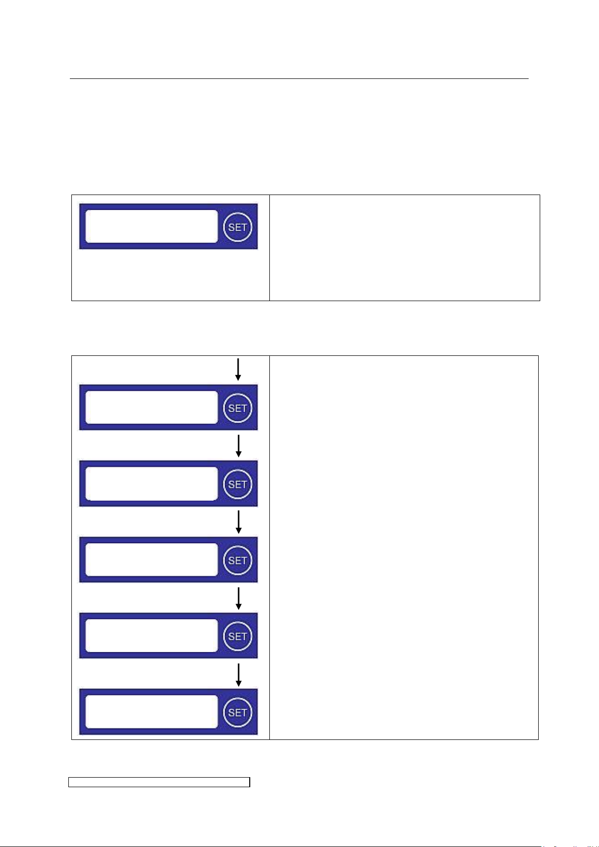
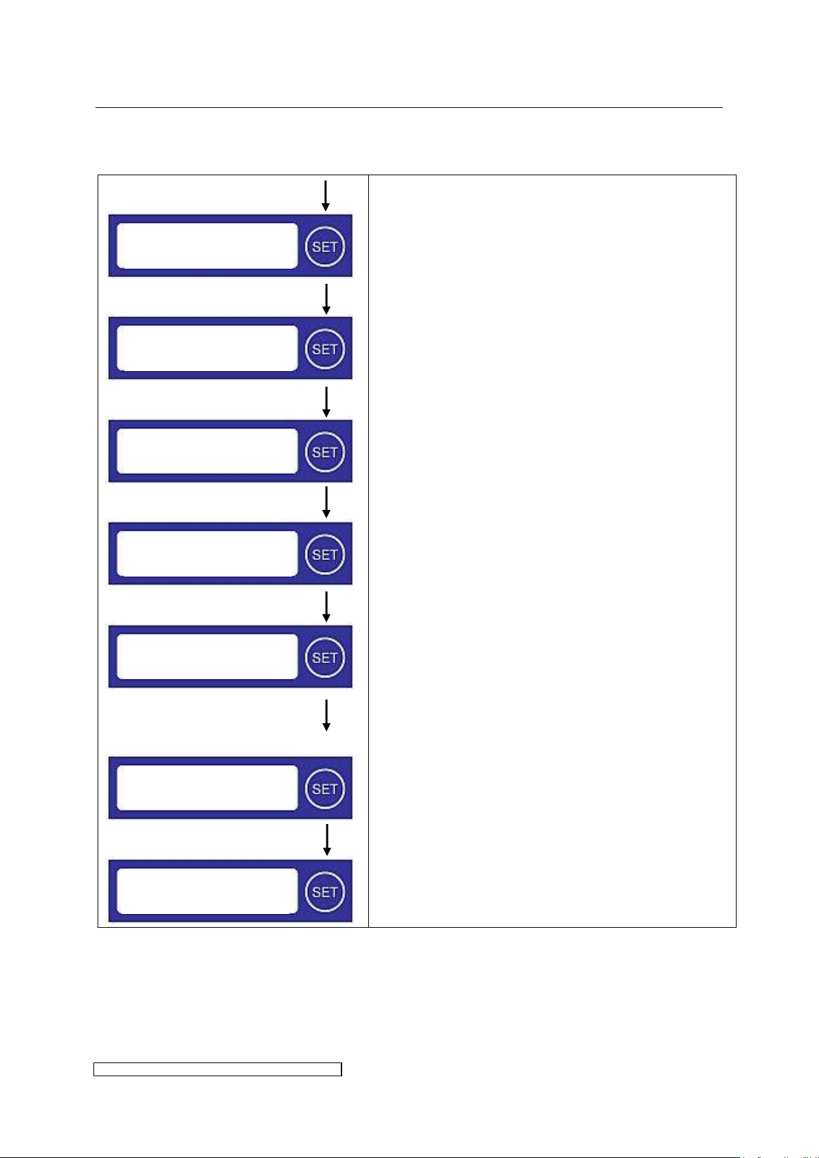
The first line gives account of the system status. As
long as the ELC is free of defects, it displays ”ELC
ready“.
The second line shows on the left side the status of
the bus connection, on the right side the appointed
bus address (default-value 01hex).
Hold > 5sec
Press < 2sec
Hold > 2sec
Press < 2sec
Hold > 2sec
If the SET-button is pressed longer than 5 seconds,
the menu item to set the high nibble will be entered.
Alongside the hexadecimal value the decimal value is
displayed.
To increment the high nibble press the SET-button
briefly (<2sec) once per step.
As soon as the desired value of the high nibble is
reached, hold the SET-button (>2sec) to jump to the
low nibble.
To increment the low nibble briefly press the SETbutton (<2sec) once per step.
To save the address hold the SET-button (>2sec).
ELC ready
No Bus 01h
Profibusaddress:
01 hex 1 dec
Profibusaddress:
11 hex 17 dec
Profibusaddress:
11 hex 17 dec
Profibusaddress:
12 hex 18 dec
ELC ready
BUS connected 12h
3.4.1 Setting up the BUS address
To set up the address the display and the pertaining SET button are used. The address space
extends from 01hex to 7Dhex (corresponding to 1 to 125). Each address may be used only once
per installation.
To leave the stand-by-status press the SET-button. The display lighting will be activated and
shows the following text:
3.4.1.1 PROFIBUS
To increment the address, the SET-button is used:
To assume the address the 24V supply has to be removed and re-applied.
Page 33
3 Installation page 29
ELC X-Series-V1.5-06.18-GB subject to technical alterations
Hold > 5sec
Press < 2sec
Hold > 2sec
Press < 2sec
Hold > 2sec
Press < 2sec
Hold > 2sec
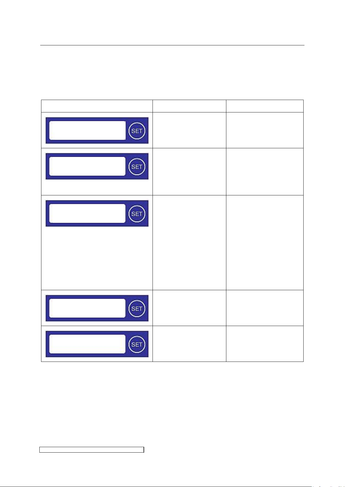
If the SET-button is pressed longer than 5 seconds,
the menu item to choose the bus connection type will
be entered.
To change the bus connection type press the SETbutton briefly (<2sec).
As soon as the desired bus connection is selected,
hold the SET-button (>2sec) to jump to address
setting.
To increment the high nibble briefly press the SETbutton (<2sec) once per step.
As soon as the desired value of the high nibble is
reached, hold the SET-button (>2sec) to jump to the
low nibble.
To increment the low nibble briefly press the SETbutton (<2sec) once per step.
To save the address hold the SET-button (>2sec).
Profibus
Modbusaddress:
01 hex 1 dec
Modbusaddress:
11 hex 17 dec
Modbusaddress:
11 hex 17 dec
ELC ready
MODBUS connected
Modbusaddress:
12 hex 18 dec
Modbus
3.4.1.2 MODBUS
To increment the address, the SET-button is used:
To assume the address the 24V supply has to be removed and re-applied.
Page 34
3 Installation page 30
ELC X-Series-V1.5-06.18-GB subject to technical alterations
Display
Status
Corrective action
ELC ready for
operation, BUSconnection ok
ELC ready for
operation, no BUSconnection
Check plug contact, bus
termination (see
paragraph 3.2.11), check
address and panelprogramming.
xx: number of the currently displayed
error
yy: total number of recorded errors
If there is more than one error
message at hand they will be
displayed on a rolling basis.
ELC not ready for
operation, BUSconnection ok
The error cause detected
by the ELC is displayed
and may be read out
additionally in the Error
Register (see paragraph
5.3.1).
ELC not ready for
operation, no BUSconnection
Check BUS-connection.
Detach ELC from mains
and restart.
Display won’t turn on
(display defect or no
supply)
Check 24V supply, switch
off and on again.
ELC ready
BUS connected 19h
ELC ready
No BUS 19h
xx/yy Error message
BUS connected 19h
xx/yy Error message
No BUS 19h
3.4.2 Checking the BUS connection and error indication
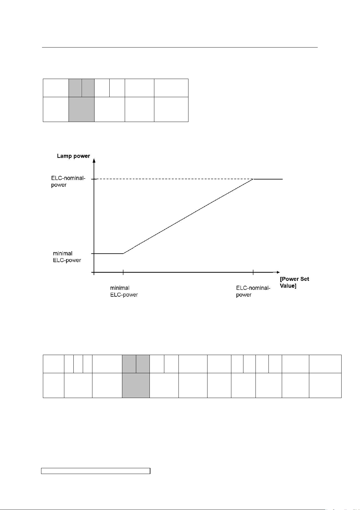
The display may be used to check the successful connection of ELC and Master and
furthermore the existence of an error (ELC not ready for operation). It is also possible to read
out error messages within the [Error Register] see paragraph 5.3.1 (detailed explanations may
be found there).
Page 35
3 Installation page 31
ELC X-Series-V1.5-06.18-GB subject to technical alterations
ByteNo.
0 1 2 3 4
5
Name
[Power
Set
Value]
[Installed
Lamp
Power]
[Lamp
Control]
[Reserved]
ByteNo.
0 1 2 3 4 5 6 7 8 9 10
11
12
13
14
15
Name
[ELC
Serial
Number]
[Software
Version]
[ELC
Nominal
Power]
[Error
Register]
[Warning
Register]
[Lamp
Status]
[Actual
Power]
[Actual
Voltage]
[Actual
Current]
[Reserved]
3.4.3 Setting lamp power via BUS
BUS-output-data (Master → ELC)
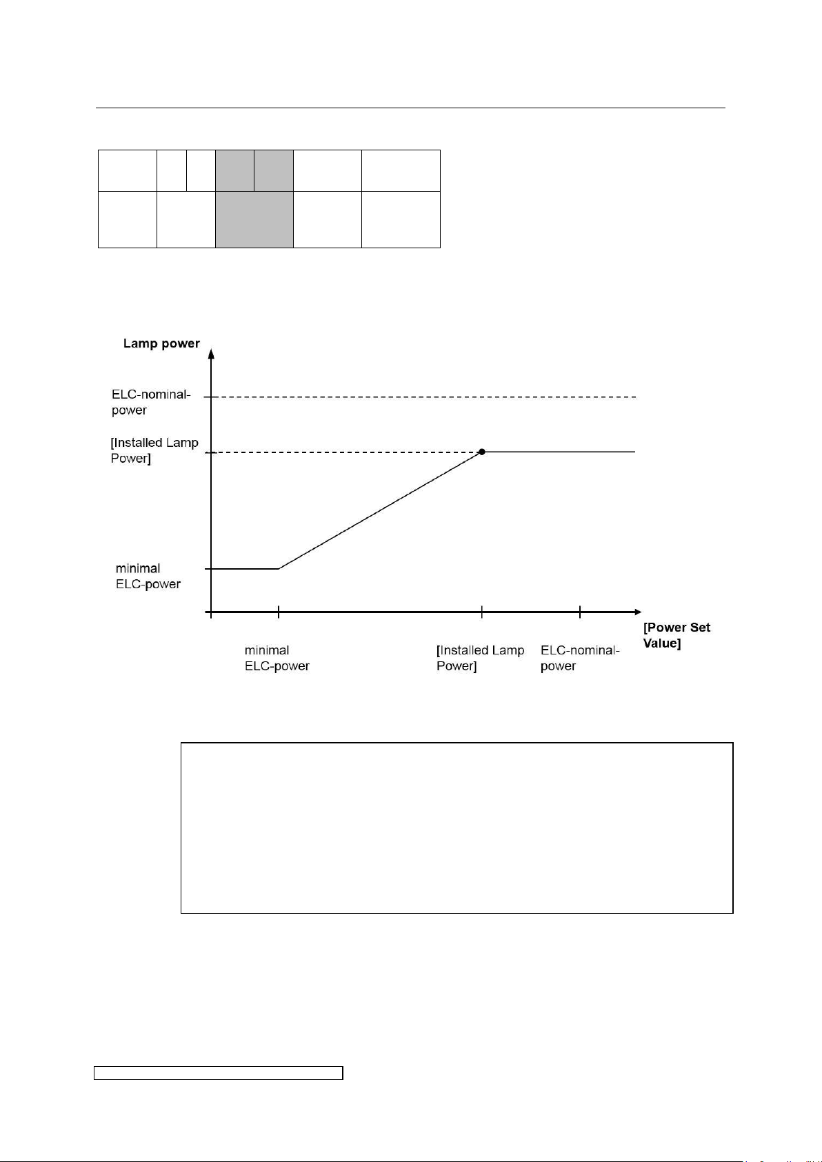
The set value for lamp power has to be written into the register [Power Set Value]. The ELC’s
output power is defined by the control characteristic of Fig. 18.
Fig. 18: Control characteristic, for real values see chapter 6
The ELC’s nominal power is written into the register [ELC Nominal Power] of the BUS-input-
data:
BUS-input-data (ELC → Master)
Page 36
3 Installation page 32
ELC X-Series-V1.5-06.18-GB subject to technical alterations
ByteNo.
0 1 2 3 4
5
Name
[Power
Set
Value]
[Installed
Lamp
Power]
[Lamp
Control]
[Reserved]
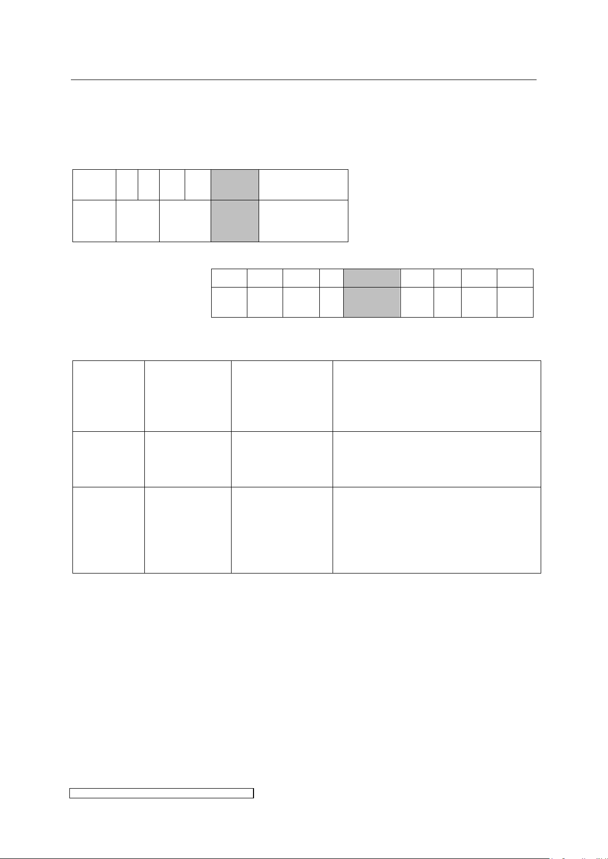
The control characteristic of Fig. 18 comes into effect, if the register [Installed
Lamp Power] is
not set
below minimum dimming range (given in % of ELC nominal power in
chapter 6)
above ELC nominal power
BUS-output-data (Master → ELC)
To limit the maximum output power, use the register [Installed Lamp Power] (see Fig. 19).
This function is appropriate if the nominal power of the lamp is lower than the nominal power
of the ELC.
Fig. 19: Limited output power characteristic
Page 37
3 Installation page 33
ELC X-Series-V1.5-06.18-GB subject to technical alterations
ByteNo.
0 1 2 3 4
5
Name
[Power
Set
Value]
[Installed
Lamp
Power]
[Lamp
Control]
[Reserved]
Bit 7 6 5 4 3 2 1 0
Name
UV
Ready
UV
Select
n/a
Extended
Range
n/a
n/a
Clear
Error
Start
Lamp
Type
Max. ambient
temperature
for lamp
operation
Max. possible
output power
(mains voltage >
400V)
Note
ELC X6B,
X8B, X12B,
X24B, X36B
55°C
Nominal output
power of the
ballast
For the given types the bit only enables
operation at 55°C.
ELC X8
extended
range
45°C
8.8kW
To keep the internal temperatures on a
constant level the maximum output
power (P_max) is decreased linearly
from 8.8 kW to 8kW between 45°C and
55°C as shown in Fig. 20.
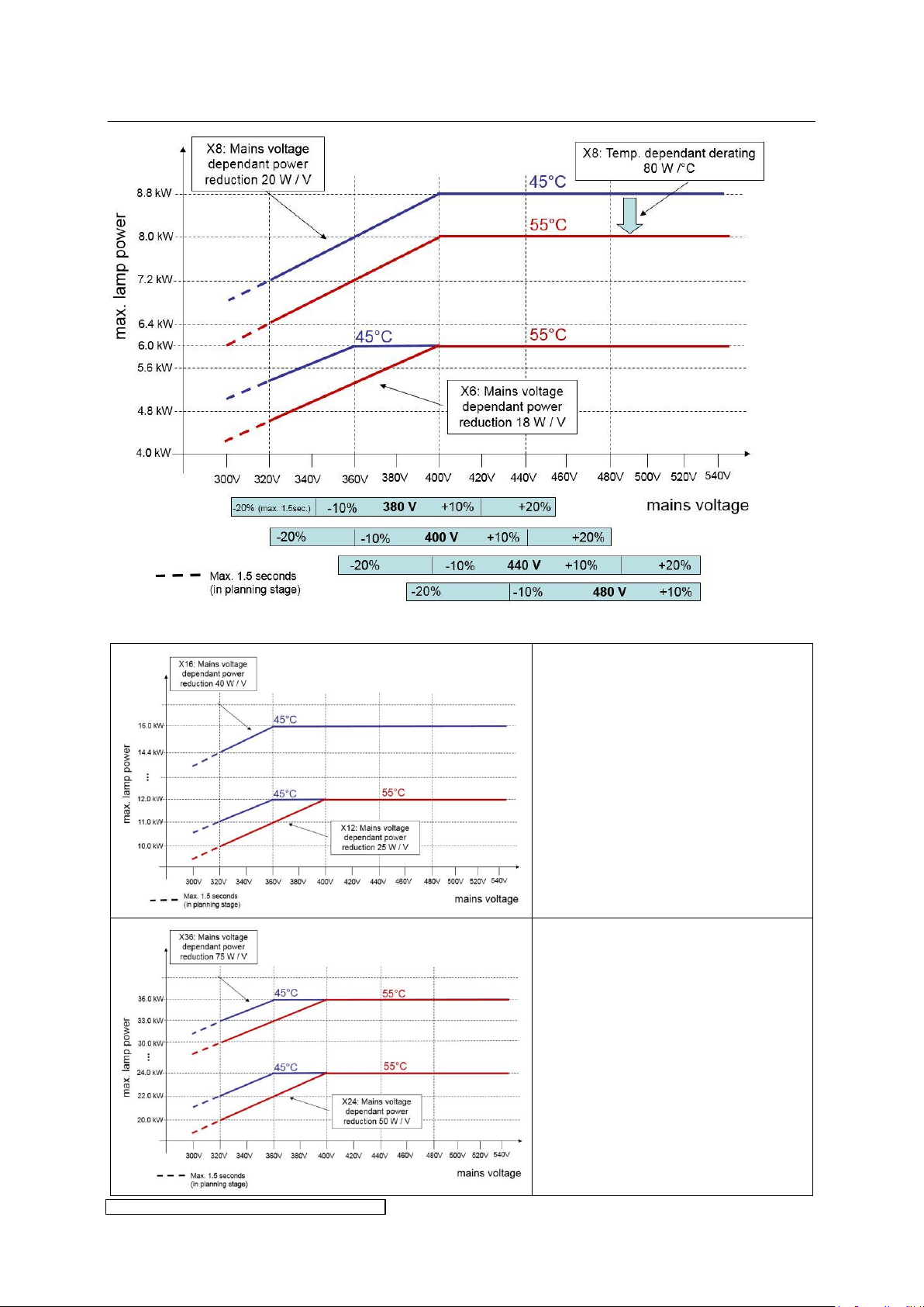
3.4.4 Extended temperature and power range
The ambient temperature range for standard operation is T_A = 5°C to 45°C. At a temperature
of 47°C the lamp is switched off automatically.
BUS-output-data (Master → ELC)
↓
If the {Extended Range}-Bit in Register [Lamp Control] is set to 1, extended functions are
activated:
This bit must be set permanently to 1 when high temperature or (at ELC X8) high power
operation is needed.
At 55°C ambient temperature there is an additional reduction of the output power if the mains
voltage falls below 400 V. This voltage dependent output power reduction is added to the
temperature dependent derating for X8 ballasts in 8.8kW operation mode.
Page 38
3 Installation page 34
ELC X-Series-V1.5-06.18-GB subject to technical alterations
Mains voltage and temperature
dependant power reduction
(exemplarily for X12 and X16)
Mains voltage and temperature
dependant power reduction
(exemplarily for X24 and X36)
Fig. 20: Mains voltage and temperature dependant power reduction (exemplarily for X6 and X8)
Page 39
3 Installation page 35
ELC X-Series-V1.5-06.18-GB subject to technical alterations
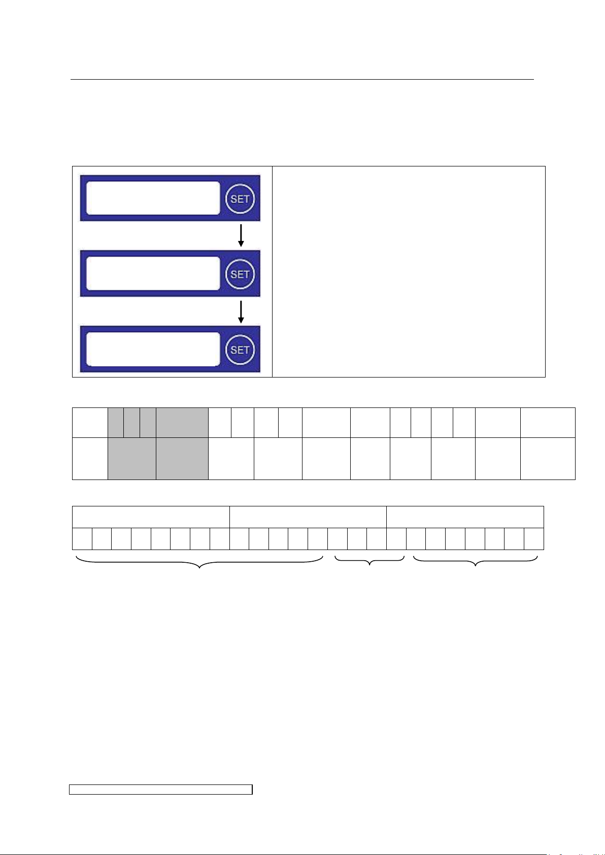
Press < 5sec
Press < 5sec
Shortly press the SET-button to reach the next menu
item.
Lamp operation data see paragraph 4.4.
Serial number and currently installed software
version in decimal values.
ByteNo.
0 1 2 3 4 5 6 7 8 9 10
11
12
13
14
15
Name
[ELC
Serial
Number]
[Software
Version]
[ELC
Nominal
Power]
[Error
Register]
[Warning
Register]
[Lamp
Status]
[Actual
Power]
[Actual
Voltage]
[Actual
Current]
[Reserved]
Byte 2
Byte 1
Byte 0
7 6 5 4 3 2 1 0 7 6 5 4 3 2 1 0 7 6 5 4 3 2 1
0
month
year
consecutive number
ELC ready
Bus connected 19h
Serial Number
Software Version
Lamp off
3.4.5 To read out ELC serial number and software version
These data may be accessed via display or BUS and may be of interest e.g. for service and in
case of a defect.
1. Display
2. BUS-input-data (ELC → Master)
↓
[ELC Serial Number] is indicated by the first three registers. The exact division of the bits into
year, month and consecutive number is defined by the brackets.
Example: 01F305hex stands for: consecutive number = 62, month = 6 and year = 5.
[Software Version] contains the currently installed software version. The high nibble
represents the main version (e.g. 10), the low-nibble the secondary version (e.g. 2). Accordingly
the example Version 10.2 is written as A2hex.
Page 40
4 Operation of the ELC page 36
ELC X-Series-V1.5-06.18-GB subject to technical alterations
Special procedure necessary for initial operation after long-time storage!
If the ELC was in storage or not connected to mains voltage longer than the
maximum storage period given in chapter 6 elevated leakage currents may arise
on the electrolytic capacitors which could damage the ELC in the worst case.
Preventive measure:
Reform the electrolytic capacitors with limited current (max. 30mA) before initial
operation. Slowly increase mains voltage with a DC-power supply or variable
transformer e.g.
4 Operation of the ELC
4.1 Initial operation
The operative parameters of the ELC, such as the scope of the trigger pulse when switching
on the lamp, are set by the manufacturer.
You must always ensure that the correct lamp type is used (see chapter 6) and that all
wiring is properly connected!
4.2 Switching on the ELC
The ELC is switched on by applying the operating mains voltage and the 24V supply.
4.3 Activating the safety circuits
Activate the safety relay
Apply the initialisation signal
Page 41
4 Operation of the ELC page 37
ELC X-Series-V1.5-06.18-GB subject to technical alterations
ByteNo.
0 1 2 3 4
5
Name
[Power
Set
Value]
[Installed
Lamp
Power]
[Lamp
Control]
[Reserved]
Bit 7 6 5 4 3 2 1 0
Name
UV
Ready
UV
Select
n/a
Extended
Range
n/a
n/a
Clear
Error
Start
Lamp
After switching on the ELC take account of the charge time given in chapter 6,
before starting the lamp.
In case of an error the ELC will not try to ignite the lamp. After eliminating the
error the [Error Register] has to be cleared additionally (see paragraph 5.3).
As long as the safety circuits are not activated the ELC will not try to ignite the
lamp (see paragraph 5.2).
4.4 Switching on the lamp
BUS-output-data (Master → ELC)
↓
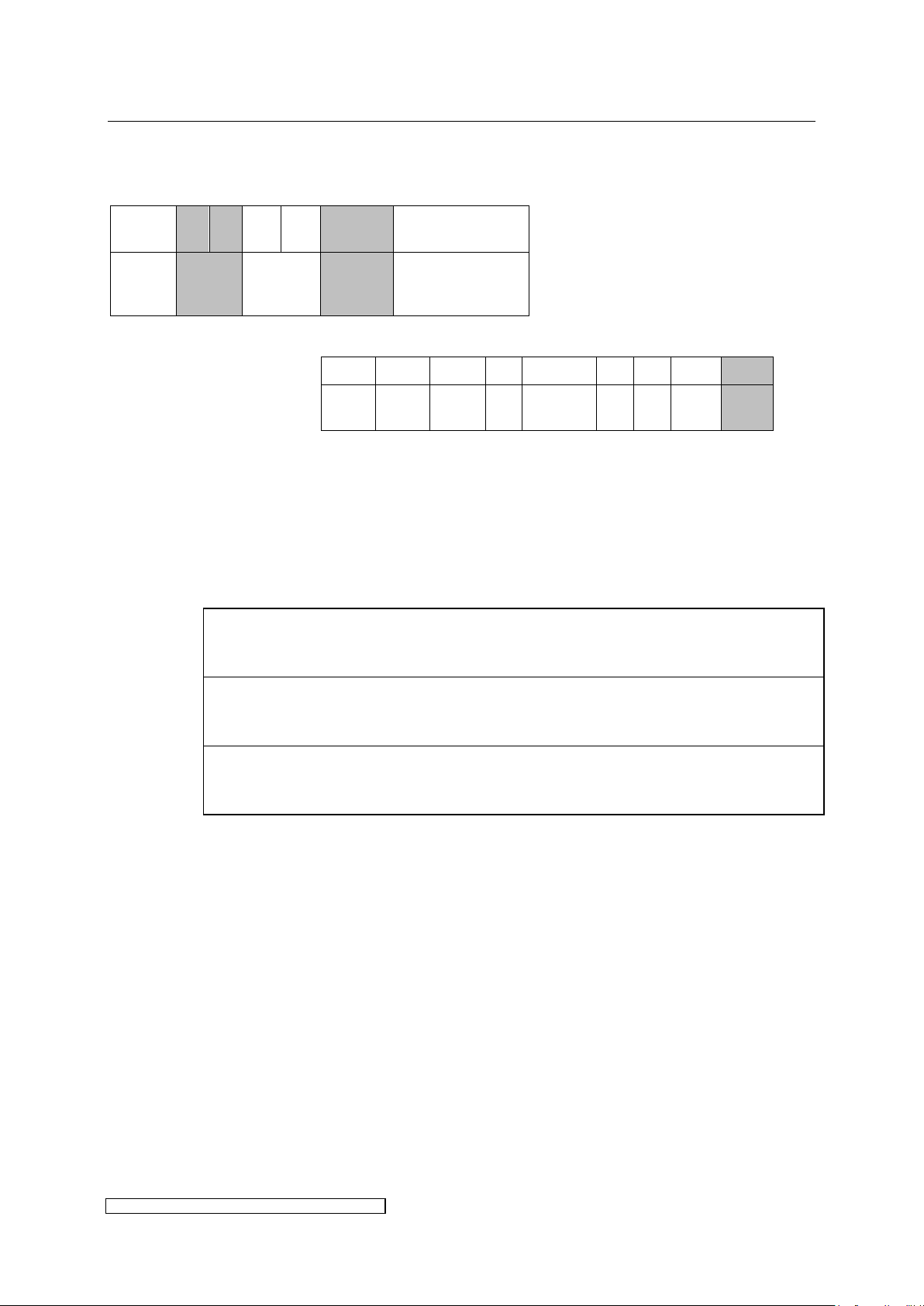
Before starting the lamp it is necessary to write the desired lamp power into the register
[Power Set Value] in Watts. To transfer the lamp and its surrounding into a thermally
stable condition, it is recommended to choose the maximum lamp power for [Power Set
Value] during the lamp run-up period.
To ignite the lamp set the {Start Lamp}-Bit in register [Lamp Control] to 1.
{n/a}: not available. These bits are reserved for future applications.
During warm-up the lamp power stays at a very low level over a longer period of time and after
approximately 60 seconds rapidly increases to its nominal power. The lamp is operated with
increased current until the nominal power is reached.
The actual condition of the lamp may be read out via the display (only actual power and power
set value), and also from register [Lamp Status] of the BUS-input-data.
Page 42
4 Operation of the ELC page 38
ELC X-Series-V1.5-06.18-GB subject to technical alterations
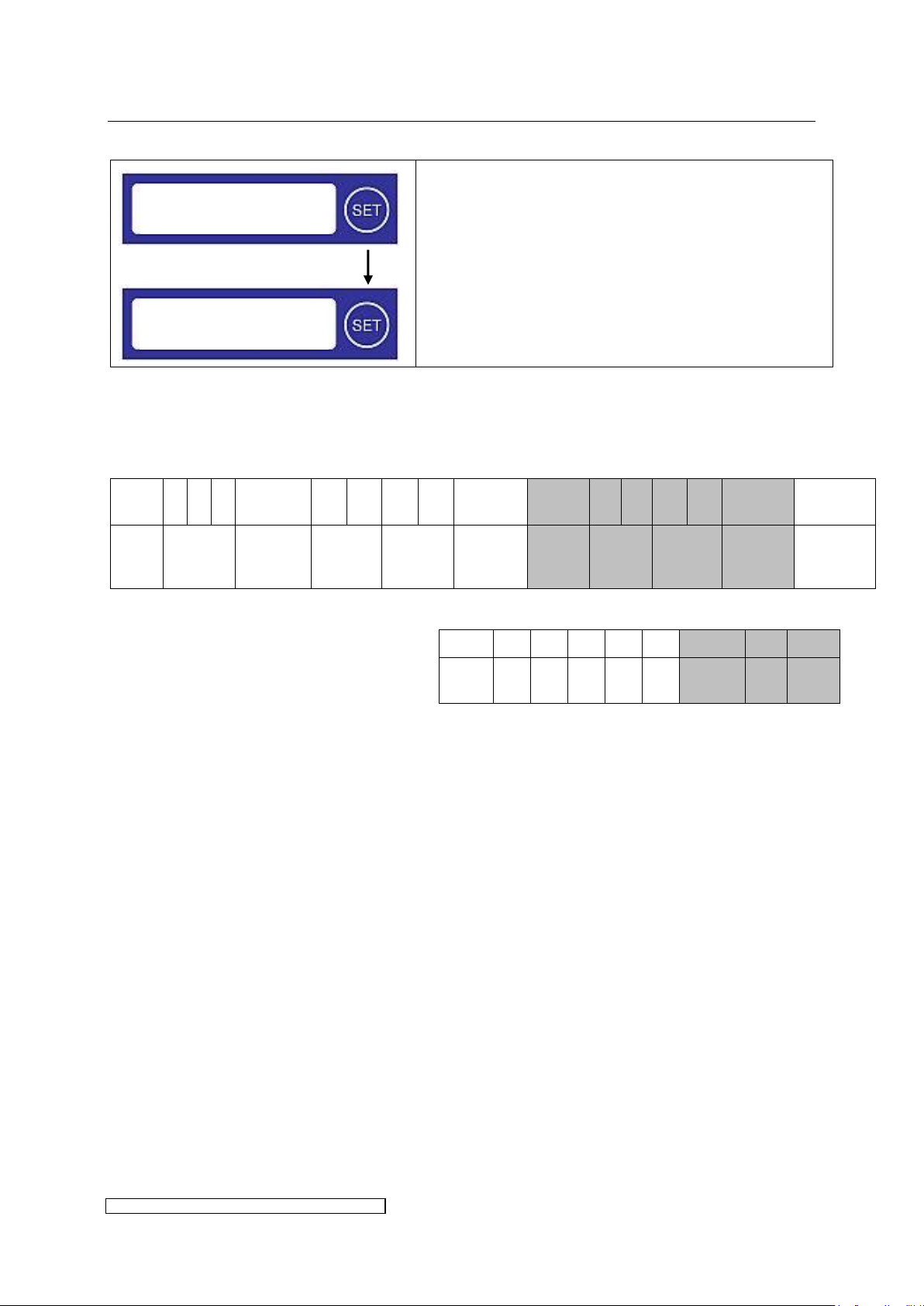
Press < 5sec
Shortly press the SET-button to get the lamp
operation data.
Lamp operation data on display:
[Actual Power]: actual power in Watts
[Power Set Value]: required power in Watts
ByteNo.
0 1 2 3 4 5 6 7 8 9 10
11
12
13
14
15
Name
[ELC
Serial
Number]
[Software
Version]
[ELC
Nominal
Power]
[Error
Register]
[Warning
Register]
[Lamp
Status]
[Actual
Power]
[Actual
Voltage]
[Actual
Current]
[Reserved]
Bit 7 6 5 4 3 2 1 0
Name
n/a
n/a
n/a
n/a
n/a
Lamp
Ignition
Run
Up
Lamp
On
ELC ready
Bus connected 19h
PLamp: 5200 W
PSet: 5200 W
1. Display
2. Register [Lamp Status]
BUS-input-data (ELC → Master)
↓
Bits in use in register [Lamp Status]:
Bit 2 {Lamp Ignition}: during the ignition phase of the lamp the ”ignition“ bit is set (value =
1, otherwise 0).
Bit 1 {Run Up}: during warm-up of the lamp the “run-up“-bit is set (value = 1, otherwise 0).
Bit 0 {Lamp On}: as soon as the lamp has reached the required power and lamp voltage is
in a steady state, the ”lamp-on“-bit will be set (value = 1, otherwise 0).
Further operation data of the continuous operation state may be read out from the registers
[Actual Power], [Actual Voltage] and [Actual Current]:
[Actual Power] returns the actual power in Watts.
[Actual Voltage] gives account of the actual lamp voltage in Volts.
[Actual Current] contains the actual current in Ampère*10 with an accuracy of 100 mA
(e.g.: [Actual Current] = 12 means 1.2 A).
Page 43
4 Operation of the ELC page 39
ELC X-Series-V1.5-06.18-GB subject to technical alterations
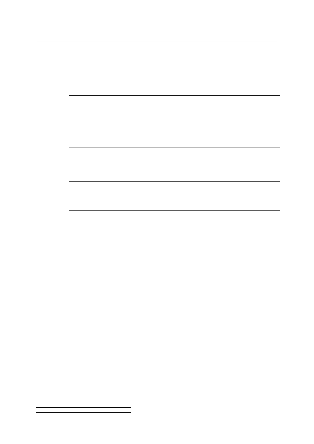
A set value of less than the minimum dimming range will automatically be
increased by the ELC to the minimum dimming range.
The warm-up time from standby operation to nominal operation depends on the
lamp's ambient conditions. If cooling is too intensive during dimming operation,
the acceleration time is prolonged.
In order to avoid heat accumulation in the ELC the 24V supply should be left on for
a few minutes. Before restarting, the lamp must be sufficiently cooled down as it
cannot be fired otherwise.
4.5 Dimming operation
After having reached nominal operation the desired lamp power can be infinitely adjusted
within the dimming range given in chapter 6.
Enter the desired power in Watts in register [Power Set Value].
4.6 Switching off the lamp
The lamp is switched off by setting the {Start Lamp}-bit to 0 in register [Lamp Control].
Page 44
5 Monitoring, warning, error, repair page 40
ELC X-Series-V1.5-06.18-GB subject to technical alterations
In case of continuous input undervoltage the lamp power is reduced by the ELC in
order to prevent an overcurrent on the input side (see output power reduction in
chapter 6).
In case of mains voltage dropouts the ELC may stop lamp operation to prevent
damage of the inverter caused by undefined supply conditions.
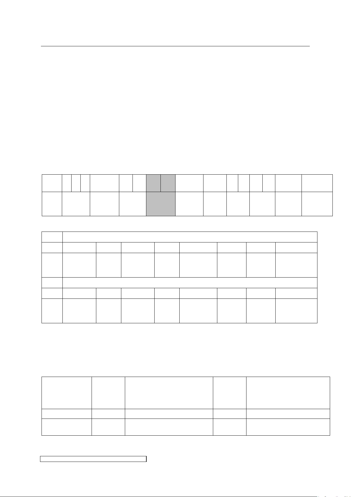
ByteNo.
0 1 2 3 4 5 6 7 8 9 10
11
12
13
14
15
Name
[ELC
Serial
Number]
[Software
Version]
[ELC
Nominal
Power]
[Error
Register]
[Warning
Register]
[Lamp
Status]
[Actual
Power]
[Actual
Voltage]
[Actual
Current]
[Reserved]
Bit 7 6 5 4 3 2 1 0
Name
Init
Signal
Ok
n/a
Lamp
Ignition
Failed
Safety
Relay
Open
n/a
n/a
Run
Up
Long
Lamp
Voltage
Low
Group 2:
Lamp operation not
possible
Group 1:
No shut down
5 Monitoring, warning, error, repair
5.1 Mains voltage monitoring
The mains voltage (L1, L2 of connector X100) is monitored during lamp operation.
5.2 Warning messages
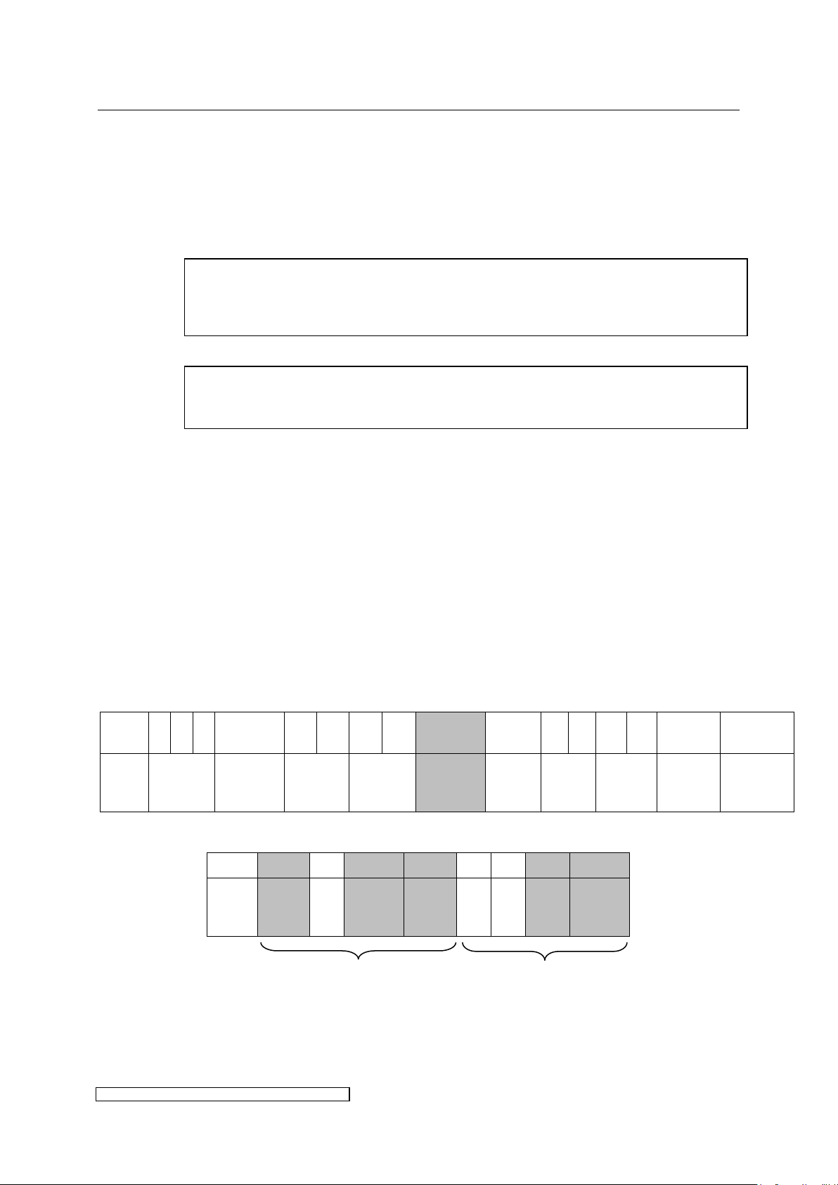
The bits in the [Warning Register] are divided into two groups:
Group1-Nibble: the bits 0-3 represent critical operating conditions of the lamp. However
they won’t shut down the lamp.
Group2-Nibble: If a bit in the Group2-nibble (bits 4-7) is set, the lamp cannot be started
or will be shut down during operation.
The bits of the [Warning Register] will automatically be reset as soon as the triggering status
has been resolved.
BUS-input-data (ELC → Master)
↓
Page 45

5 Monitoring, warning, error, repair page 41
ELC X-Series-V1.5-06.18-GB subject to technical alterations
Bit 0: The {Lamp Voltage Low}-bit is set if the lamp voltage is lower than the
threshold voltage given in chapter 6. A possible reason is a strong lamp
cooling especially in dimming operation. This could cause a long run up time
to regain the nominal power.
Please consider that the ELC cannot distinguish lamps of different nominal
voltages. If the ELC is used on purpose to operate a lamp with a lower nominal
voltage the bit will be set although full lamp voltage is reached.
This bit will be reset if the lamp voltage exceeds the threshold voltage.
Bit 1: During run-up the lamp power normally increases to the desired lamp power
(Register [Power Set Value]). The {Run Up Long}-bit is set, if 95% of the
required lamp power are not reached within 3 min. Possible reasons are an
incorrect lamp type or excessive cooling of the lamp.
Reset occurs as soon as the {Start Lamp}-bit in register [Lamp Control] is
set to 0 (the lamp being thus actively shut down by the operator via the BUS
output data).
Bit 4: The {Safety Relay Open} bit is set if the safety relay is not closed (e.g. on
emergency shutdown). There are two different cases:
If in register [Lamp Control] {Start Lamp} bit is 0, the {Safety Relay Open}
bit is automatically reset as soon as the safety relay is closed.
During lamp operation ({Start Lamp}=1 in [Lamp Control]) the {Safety
Relay Open} bit remains set and the lamp will be shut down by the ELC. In
this case {Safety Relay Open} will only be reset if {Start Lamp} in [Lamp
Control] is reset and the safety relay has been closed.
Bit 5: If the ELC cannot ignite the lamp the {Lamp Ignition Failed} bit will be set and
remains in this status as long as {Start Lamp}=1 in [Lamp Control]. The {Lamp
Ignition Failed} bit is reset as soon as {Start Lamp} in [Lamp Control] is reset.
Bit 7: The {Init Signal Ok} bit reflects the status of the Init-Signal-Pin X806.3 of the
initialisation signal (see paragraph 3.3.2).
{Init Signal Ok}=1 means 24 V on X806.3, the lamp may be ignited and
operated normally.
{Init Signal Ok}=0 means 0 V on X806.3, the lamp cannot be operated.
To render the ELC operational again in case {Init Signal Ok}=0 the
initialisation signal on X806.3 has to be 24V and the start signal {Start Lamp}
has to be reset.
Bit 2, Bit 3 und Bit 6: {n/a} bits (not available) are reserved for future applications.
Page 46
5 Monitoring, warning, error, repair page 42
ELC X-Series-V1.5-06.18-GB subject to technical alterations
ByteNo.
0 1 2 3 4 5 6 7 8 9 10
11
12
13
14
15
Name
[ELC
Serial
Number]
[Software
Version]
[ELC
Nominal
Power]
[Error
Register]
[Warning
Register]
[Lamp
Status]
[Actual
Power]
[Actual
Voltage]
[Actual
Current]
[Reserved]
Byte
6
Bit
15
14
13
12
11
10 9 8
Name
CanIntern
Slave
Lamp
Power
Low
Supply
ZVS
Earth
Leakage
Fault
Measurement
Overcurrent
Byte
7
Bit 7 6 5 4 3 2 1 0
Name
Lamp
Voltage
High
Overvoltage
Bus
Connection
Error
Internal
ELC
Temperature
High
Fan Error
Mains
Voltage
Low
DC-Link
Undervoltage
Display message
Bit set in
Error
register
Description
{Bit-name in error register}
Detection
only in
lamp
operation
Corrective action
ELC ready
-
Ballast is ready for operation.
No
-
Display is off
-
No 24V supply or display defect.
No
Check 24V supply, switch off
and on again.
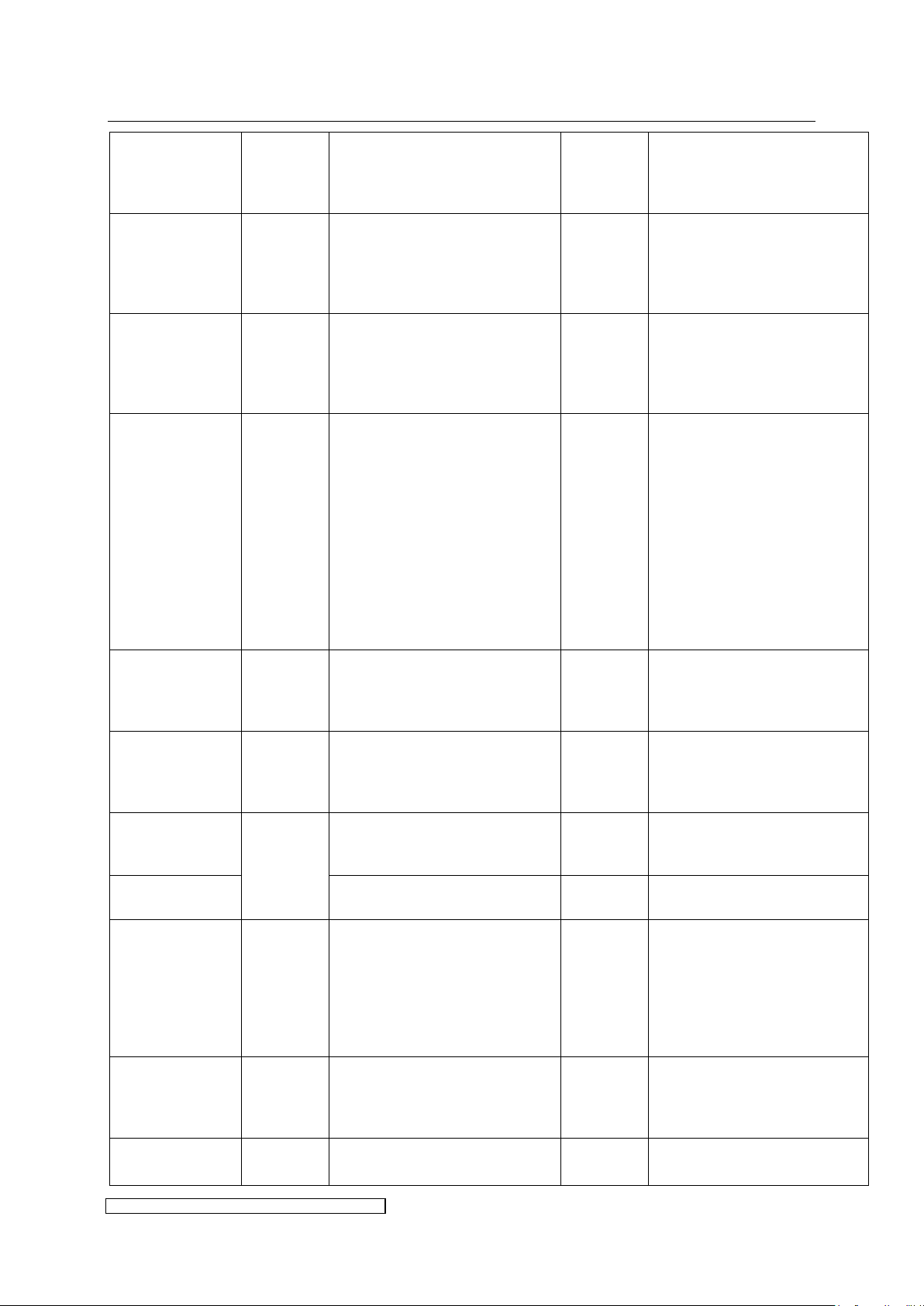
5.3 Error
5.3.1 Error messages
Effects of an error:
The lamp will be immediately shut down,
In case of an error the display is blinking and the error is shown in clear text. In case of
several error messages they will be displayed on a rolling basis.
For description of the errors and trouble shooting see chapter 5.3.2
Bits in the [Error Register] will be set as soon as the correspondent error occurs and must
be reset for further lamp operation (see chapter 5.3.4).
BUS-input-data (ELC → Master)
↓
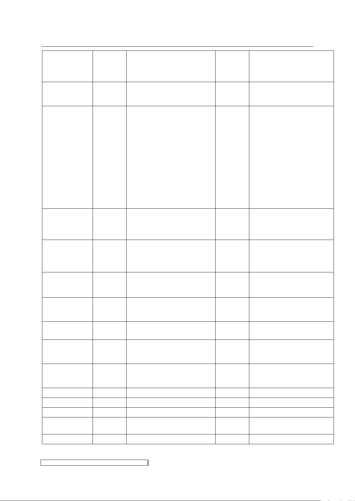
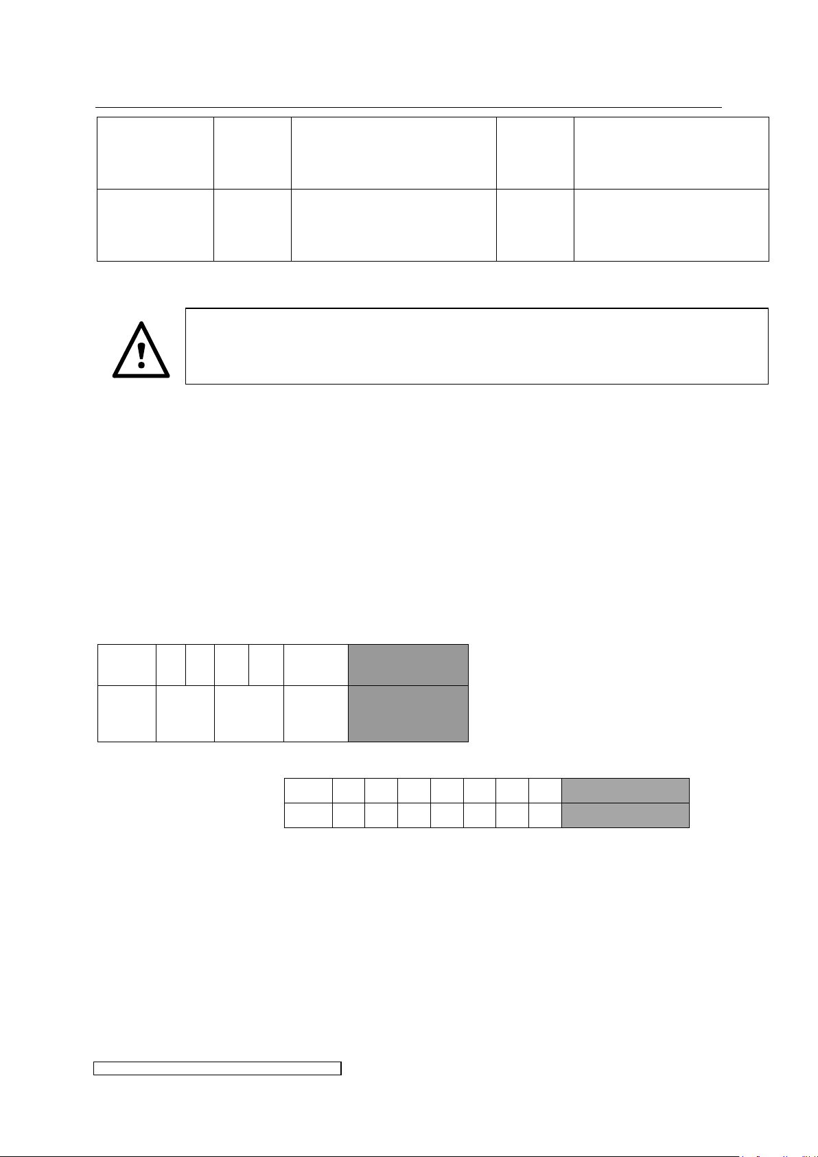
5.3.2 Display messages and trouble shooting
The following table gives a connection between display messages and bit-names in the [Error
Register]. It also describes the most common causes for an error and possible corrective
actions. A more detailed trouble shooting list is available on demand.
Page 47
5 Monitoring, warning, error, repair page 43
ELC X-Series-V1.5-06.18-GB subject to technical alterations
Display message
Bit set in
error
register
Description
{Bit-name in error register}
Detection
only in
lamp
operation
Corrective action
DC Link
Bit 0
(0x0001)
{DC-Link-Undervoltage}:
internal dc link voltage is low
due to low mains voltage, blown
internal fuses or other defective
parts inside the ELC.
Yes
Check fuses
Check mains voltage
Consider charge time
Mains volt
Bit 1
(0x0002)
{Mains Voltage Low}: input
voltage measurement detects
mains voltage drop or
fluctuations (for shut down
voltage see chapter 6).
Yes
Check connections
Check mains voltage
Fan error
Bit 2
(0x0004)
{Fan Error}: malfunction of one
or more of the three ELC-fans
(one main fan, two internal),
detection via speed control.
No for
internal
fans.
The main
fan is only
running
during
lamp
operation
Check for:
ball bearing defect
tight connection of front
hood (correct engagement
of connector between
front hood and main
board)
corroded cable connection
on entry of the fan
blocked rotors
squeezed cables
Change fan or remove cause.
Temp high
Bit 3
(0x0008)
{ELC Temperature High}:
ambient or internal
temperature too high.
No
Check ambient temperature
and fans of cabinet (direction
of air current, change filter
mats).
Internal
Bit 4
(0x0010)
{Internal}: problems of
internal communication
between controllers or failed
“self-check” of the controllers.
No
Switch off and on the 24V
supply.
Bus error
Bit 5
(0x0020)
{Bus Connection Error}: field
bus connection fails during
lamp operation.
Yes
Check bus termination and
connector contact.
X6CA failure
Internal communication fails.
No
Send back for repair by
manufacturer.
Over volt.
Bit 6
(0x0040)
{Overvoltage}: short peak
overvoltage on the lamp
exceeds nominal ignition
voltage during ignition or
operation due to an internal
problem of the ELC or damaged
cables on lamp circuitry.
Yes
Check lamp wiring concerning
insulation defects.
Lamp v.hi
Bit 7
(0x0080)
{Lamp Voltage High}: the lamp
voltage exceeds a threshold
critical for the ELC. Usually the
lamp type is not correct.
Yes
Check lamp type and lamp
connectors/sockets, switch
lamp.
Over curr.
Bit 8
(0x0100)
{Overcurrent}: internal
overcurrent.
Yes
Check for short in lamp
circuit.
Page 48
5 Monitoring, warning, error, repair page 44
ELC X-Series-V1.5-06.18-GB subject to technical alterations
Display message
Bit set in
Error
register
Description
{Bit-name in error register}
Detection
only in
lamp
operation
Corrective action
Measurement
Bit 9
(0x0200)
{Measurement}: problems with
the internal measurement
circuits.
Yes
Check for short in lamp
circuit.
Earthfault
Bit 10
(0x0400)
{Earth Leakage Fault}:
insulation resistance between
lamp circuitry and earth gets
lower than 200kOhm (e.g. in
case of bad wiring on the lamp,
high air humidity, polluted
cables or connections).
In order to avoid an unwanted
reaction of the earth fault
control during faultless
operation, the insulation
resistance of the lamp cables
and all lamp connectors must
be greater than 10 MΩ.
No
Check lamp wiring and
insulation resistance.
ZVS
Bit 11
(0x0800)
{ZVS}: the ELC detects
switching losses of the power
semiconductors and shuts
down to prevent damages.
Yes
External reasons might be
flashovers in the lamp circuit.
VBSupply
Bit 12
(0x1000)
{Supply}: indicates problems of
internal low voltage supply due
to internal problems or low
mains voltage.
Yes
Check for low mains voltage.
Check 24V-supply.
PLow
Bit 13
(0x2000)
{Lamp Power Low}: lamp
extinguishes (e.g. cooling too
strong or lamp defect).
Yes
Reduce cooling or replace
lamp.
Check lamp wiring.
Slave
Bit 14
(0x4000)
{Slave}: error detected in slave
modul or faulty connection
between master and slave.
No
Check internal wiring.
CanIntern
Bit 15
(0x8000)
{CanIntern}: interference in
modul-internal communication.
No
Check internal wiring.
No Profibus
-
Profibus connection is not
detected.
No lamp
operation
possible
Check termination and
connector.
No Modbus
-
Modbus connection is not
detected.
No lamp
operation
possible
Check termination and
connector.
Profibus ok
-
Profibus connection is detected.
No
-
Modbus ok
-
Modbus connection is detected.
No
-
Serial: nnnnnnnn
-
ELC serial number is displayed.
No
-
SW Version:
nnnnnnnn
-
ELC software version is
displayed.
No
-
Lamp is off
-
Currently no lamp operation.
No
-
Page 49
5 Monitoring, warning, error, repair page 45
ELC X-Series-V1.5-06.18-GB subject to technical alterations
Display message
Bit set in
Error
register
Description
{Bit-name in error register}
Detection
only in
lamp
operation
Corrective action
PLamp: xxxxx
PSet: yyyyy
-
Indication of actual power in
Watts
Indication of required power in
Watts
Yes
-
Replace a blown fuse only by fuses of types authorised by the manufacturer (see
chapter 6). By using the wrong fuse type extensive damage might be done to the boards,
rendering economic repairs impossible.
ByteNr.
0 1 2 3 4
5
Name
[Power
Set
Value]
[Installed
Lamp
Power]
[Lamp
Control]
[Special Function]
Bit 7 6 5 4 3 2 1 0
Name
n/a
n/a
n/a
n/a
n/a
n/a
n/a
Earthfault UV Ready
5.3.3 Earthfault indication via Special Function Register in MODBUS control
With the [Special Function] register the UV Ready relay (X805.10 and X805.11, also see
paragraph 3.2.13) can be changed to function as an earthfault indicator. When setting the
{Earthfault UV Ready} bit to “1”, the UV Ready relay functions as an opener in case of an
earthfault. This bit can be written once and will stay remanent until the 24V is switched of, or
it is reset by software via Modbus.
If the ELC detects an earthfault and the {Earthfault UV Ready} bit is set, the UV Ready relay
will open its contact, regardless if the lamp is running or switched of. To close the relay again,
the error must be reset by writing a “1” to the {Clear Error} bit in register [Lamp Control].
FIELDBUS-output data (Master → ELC)
↓
Page 50
5 Monitoring, warning, error, repair page 46
ELC X-Series-V1.5-06.18-GB subject to technical alterations
ByteNr.
0 1 2 3 4
5
Name
[Power
Set
Value]
[Installed
Lamp
Power]
[Lamp
Control]
[Reserved]
Bit 7 6 5 4 3 2 1 0
Name
n/a
n/a
n/a
n/a
n/a
n/a
Clear
Error
Start
Lamp
Do not open the ELC before it is disconnected from the mains. BEWARE OF
RESIDUAL VOLTAGE! The unit may still be live up to several minutes (see label in
the ballast) after it has been switched off.
Beware of possible damage to the boards due to electrostatic discharge. Handle
the boards possibly in an electrostatic protected area or with appropriate
precautions. The technician should be earthed (e.g. use of an ESD-Service Kit with
earthed mat and wristband).
Beware the weight of the exchange units. Carry the board at the front and at the
back in the section of the cooler. Lateral carrying bends the board and can
predamage components.
5.3.4 Resetting the error register
Each error has to be acknowledged by setting the {Clear Error} bit in register [Lamp Control]
to “1”. First of all set the {Start Lamp} bit in register [Lamp Control] to 0. Then only the
transgression of the {Clear Error} bit from “0” to “1” can reset the [Error Register]. After the
BUS has transmitted the [Lamp Control] Register (check e.g. via the [Error Register]: if error
eliminated all error bits are „0“ again) and after an ELC internal synchronisation time of
additional 15 ms, the {Clear Error}-bit has to be reset to „0“.
BUS-output data (Master → ELC)
↓
5.3.5 Exchanging the main board
In general we recommend to exchange the whole ballast if an error persists and lamp
operation is no longer possible. If the way of installation renders removal of the housing
difficult or impossible the main board (including cooler and control boards) may be exchanged
solely.
Page 51
5 Monitoring, warning, error, repair page 47
ELC X-Series-V1.5-06.18-GB subject to technical alterations
Procedure:
Disconnect the ELC from the mains. Verify whether the ELC is de-energised and secured
from unintentional restart.
Remove front hood.
Disconnect all incoming cable plugs (see chapter 3.2) from the board.
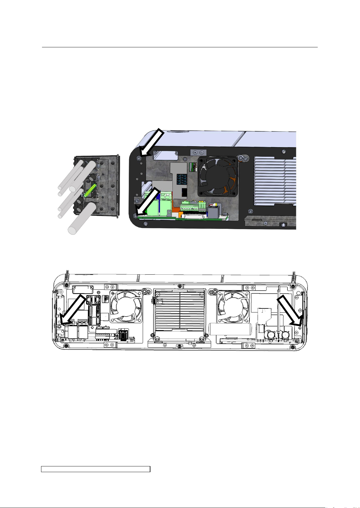
To safe time the cable gasket with attached cables may be reused on the new ballast. Only
loosen the marked screws of the following picture and pull out the cable gasket along the
slotted holes.
Respect the discharge time of residual voltage according to the label above the mains
connector in the ballast.
Remove the screws marked in the picture:
Page 52
5 Monitoring, warning, error, repair page 48
ELC X-Series-V1.5-06.18-GB subject to technical alterations
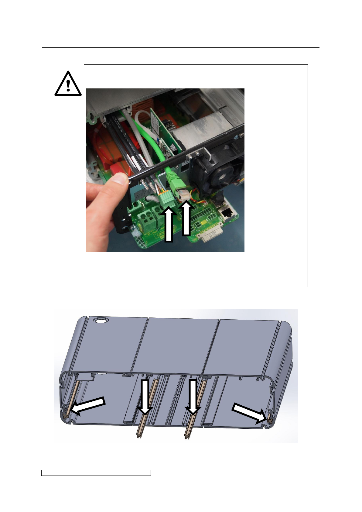
Attention with ELC X16-36: At first pull out the board for less than 10cm.
Carefully pull the marked connectors through the slot:
Then extract the whole board.
Non-observance can lead to damage to the cables in the form of cable
breaks.
Pull out main board with respect to the following rules:
Check position of the plastic guide bars before installing the new board. Pull out the
lower guide bars for approx. 5cm to insert the board more easily.
Fix cable gasket to the new ballast.
Page 53
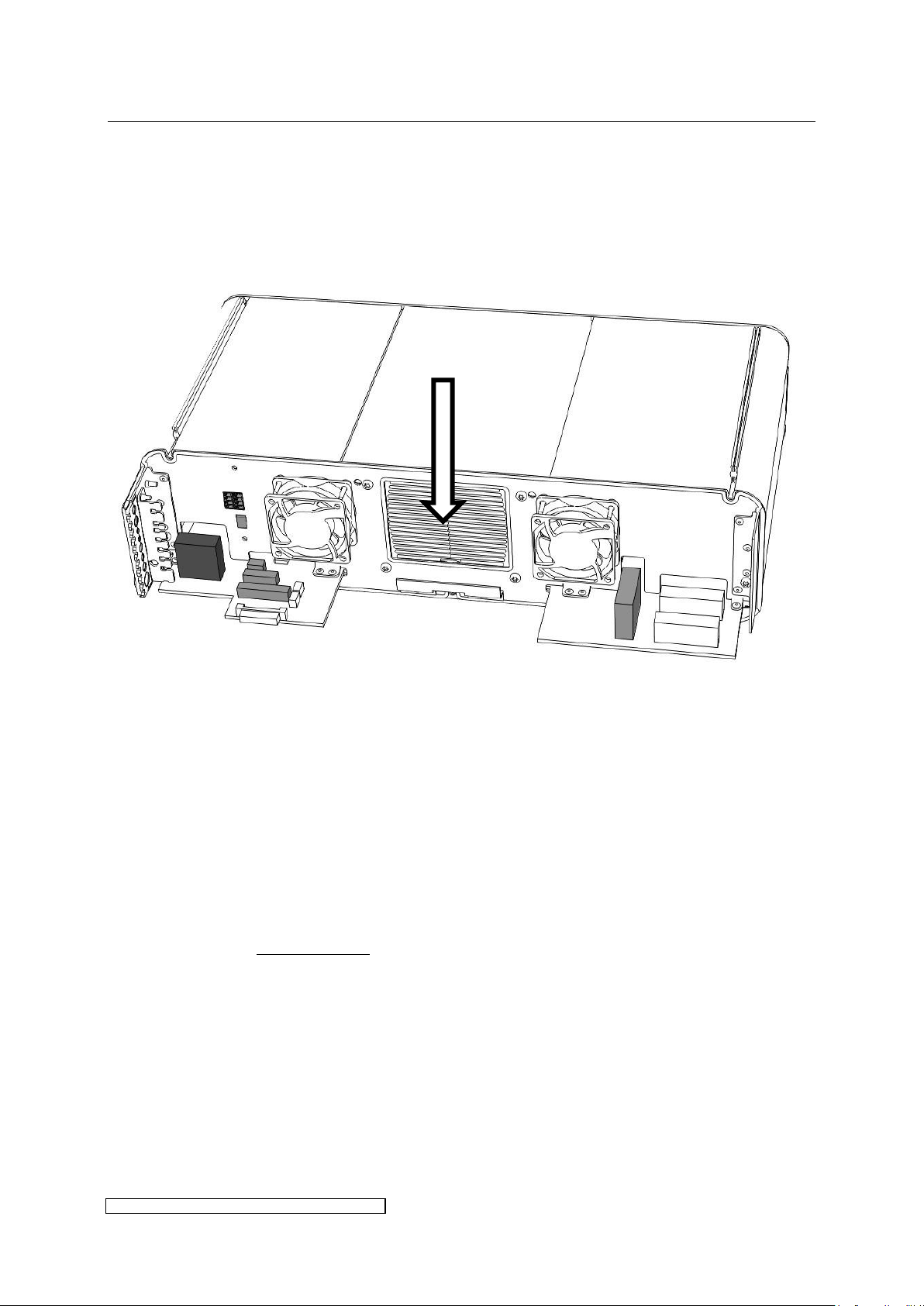
5 Monitoring, warning, error, repair page 49
ELC X-Series-V1.5-06.18-GB subject to technical alterations
5.4 Maintenance
In case of strongly contaminated cooling air, especially adhesive dust particles, we
recommend to vacuum the cooler on a regular basis or to filter the cooling air. This way
frequent temperature errors may be avoided.
After removal of the front hood the cooler is accessible:
5.5 Repair ELC
Only the manufacturer is permitted to repair the ELC. In case of failure please contact the
following address:
eta plus electronic gmbh
Lauterstraße 29
D-72622 Nürtingen
Tel: +49 7022 / 6002-80
Fax: +49 7022 / 65854
e-mail: [email protected]
Page 54
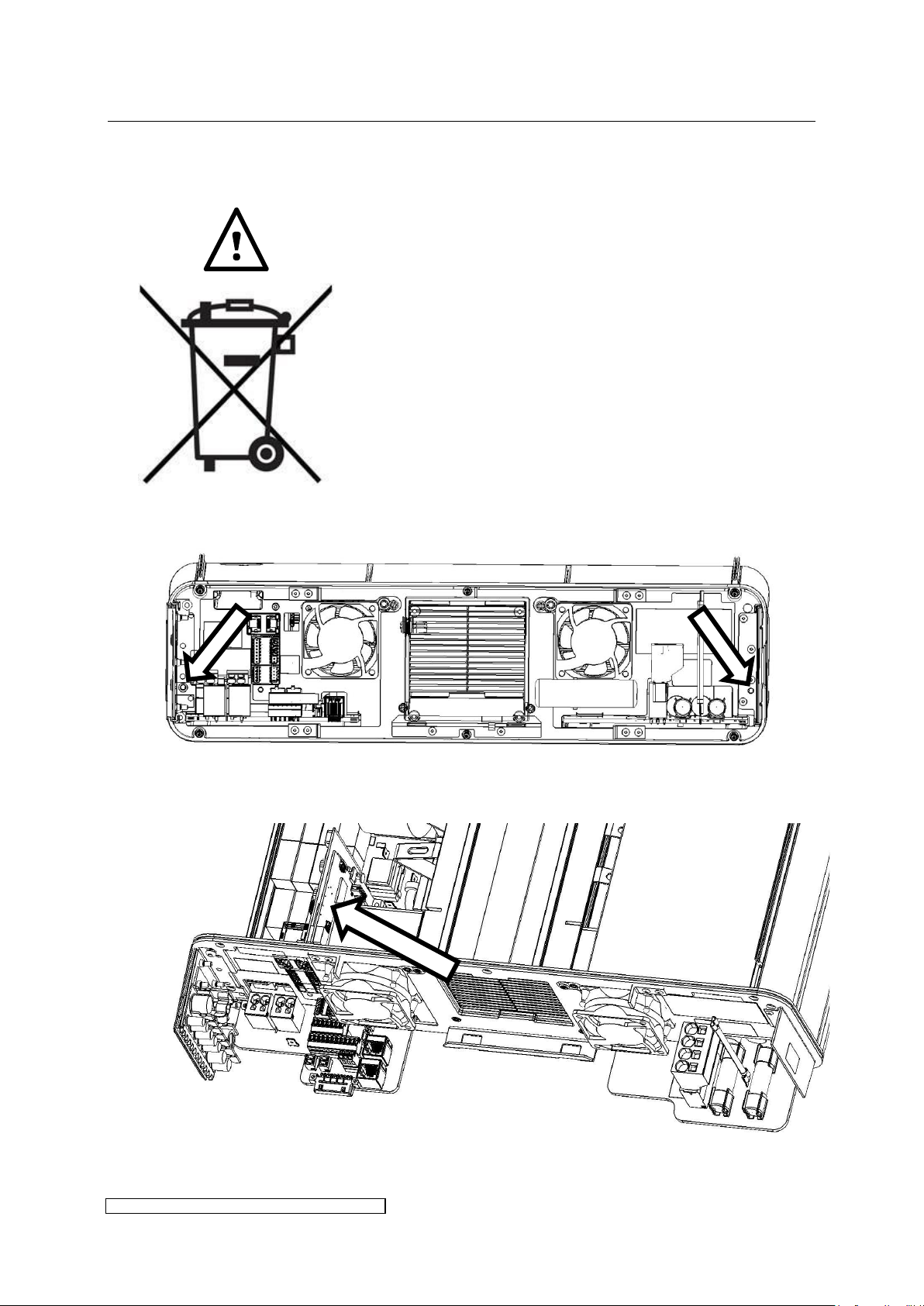
5 Monitoring, warning, error, repair page 50
ELC X-Series-V1.5-06.18-GB subject to technical alterations
ELC of type X providing powers of 12kW or more contain a
lithium battery. Mind the following hints at disposal of the
ballast:
Lithium batteries are save when adequately
handled.
Improper use or storage can lead to fires.
Don’t use defect lithium batteries.
Cover the poles by taping during storage and
disposal to prevent shorts.
Dispose of used batteries and accumulators
appropriately in collection boxes (commerce) or
municipal collection points.
Removal of the battery from the ELC:
Remove front hood and the screws marked in the picture above, pull out base plate.
The battery is located in the left hand part of the ballast on the vertically mounted
X6C-board:
Fig. 21: Position of the battery
5.6 Disposal of ELC
Dispose of the ELC according to the national law in force.
Page 55
6 Technical Data page 51
ELC X-Series-V1.5-06.18-GB subject to technical alterations
Type
ELC X4-40
Power factor
typ. > 97%
Power efficiency
typ. 94%
Nominal power range
800 W – 4000 W
Type
ELC X4-40
Nominal supply voltage
400 V - 480 V
Operating supply voltage range
400 V - 480 V
Nominal supply current
11.0 – 9.1 A
Max. supply current
12.1 A
Line protection*
min. 16 A
Internal fuse at mains input
(F200, F201)
SIBA 5017906.25 URZ 25 A / 690 V / 10x38 mm or
comparable type
class gR
Arcing-I²t-Value 52 A²s, Total I²t-Value (@AC 660 V) 650
A²s
Mains frequency
50 / 60 Hz
Min. mains voltage (shut down
voltage)
320 V
Output power reduction in case
of low mains voltage
from approx. 360 V – 320 V:
13 W / V
Abs. max. mains voltage
528 V
Leakage current
typ. 10 mA
Insulation resistance between
primary and PE
> 30 MΩ
Discharching time of residual
voltage after mains
disconnection
according to label above mains connector in the ballast
Charge time (minimum time
between switch on of the ELC
and starting the lamp)
16 s
6 Technical Data
6.1 ELC X4
Output power characteristics
Electrical characteristics
*Line protection: automatic cut-out characteristic C
Page 56
6 Technical Data page 52
ELC X-Series-V1.5-06.18-GB subject to technical alterations
Type
ELC X4-40
Nominal lamp power
4 kW
Nominal lamp voltage
400 V
Tolerance lamp voltage
nominal voltage ± 5 %
Threshold voltage of {lamp
voltage low} warning bit
300 V
Ignition voltage / period
approx. 1000 V_rms / < 1 s, 5 trials
The use of cable types which have not been approved by the manufacturer
can lead to malfunction. The possibility of damage to the electronic ballast
cannot be excluded.
Type
ELC X4-40
Article no. 8092
DIN VDE
U0/U = 0.8/1.4kV
UL: 1000V
2x2.5 mm²
Ø 9.3 mm
UL AWM Style 21179, not
licensend for marine
application
2-40 m
Article no. 8044
U0/U = 0.6/1kV
2x2.5 mm²
Ø 9.8 mm
GL-approved
2-40 m
Article no. 8068
U0/U = 0.9/1.6kV
2x2.5 mm²
Ø 10.5 mm
2-40 m
Article no. 8045*
U0/U = 1.8/3kV
2x4mm²
OD-Ø 16.9mm
GL-approved
on request
Lamp characteristics
Lamp feeder cable: approved types and lengths
The data refers to the distance between ELC and lamp.
* This cable cannot be connected directly to the ELC due to the diameter.
Page 57
6 Technical Data page 53
ELC X-Series-V1.5-06.18-GB subject to technical alterations
Type
ELC X4-40
Dimensions
(approx. H x W x D)
125 x 470 (±1mm) x 260 mm
Weight (approx.)
11 kg
Installation position
vertical or horizontal as described in 3.1
Type
ELC X4-40
Current requirement of 24Vsupply (X805.5)
2.2 A max. for ELC control circuitry
Output currents of X806 Pins 5 + 6 have to be added
Baud rate
PROFIBUS: 500 kBit
MODBUS: Baud rate 19200, 8 Databits, even parity, 1
Start/Stop Bit
Modbus timeout
60 s
Max. number of devices per
BUS segment
recommended with PROFIBUS: 40
when operating in compliance with ANSI/EIA/TIA-485-
A-98: 50
Type
ELC X4-40
Humidity
max. 85%, non-condensing
Ambient operation temperature
5°C to +45°C
Ambient storage temperature
-20°C to +70°C during storage and transportation,
before initial operation leave at least 4 hrs at room
temperature
Maximum storage period
2 years (also see paragraph 4.2)
Air flow
max. 200 m³ / h at T_A >35°C
typ. 100 m³ / h
Altitude of site
max. 4000 m above sea level
up to 2000 m above sea level without derating
2000 m to 4000 m above sea level: 1.5% / 100 m power
reduction effected by ELC-control (2800 W at 4000 m
above sea level)
Mechanical characteristics
Control characteristics
Ambient conditions
Page 58
6 Technical Data page 54
ELC X-Series-V1.5-06.18-GB subject to technical alterations
Type
ELC X4-40
Protection
IP 54
Protection of front fan IP x4
Note: protection is only guaranteed if cables of the
given diameters are used (see paragraph 3.2.2)
EMC
EN 55011
EN 61000-3-3
EN 61000-6-2
Safety
EN 50178
UL
E349667
Marine approval
- -
Certification
Page 59
6 Technical Data page 55
ELC X-Series-V1.5-06.18-GB subject to technical alterations
Type
ELC X6-60
ELC X6B-60
ELC X6i-60
Power factor
typ. > 97%
Power efficiency
typ. 94%
Nominal power range
840 W – 6050 W
Type
ELC X6-60
ELC X6B-60
ELC X6i-60
Nominal supply voltage
400 V - 480 V
440 V
400 V - 480 V
Operating supply voltage range
400 V - 480 V
Nominal supply current
15.9 A - 13.4 A
14.5 A
15.9 A - 13.4 A
Max. supply current
18 A
Line protection*
min. 20 A
Internal fuse at mains input
(F100, F101)
SIBA 5017906.25 URZ 25A / 690V / 10x38mm or comparable type
class gR
Arcing-I²t-Value 52A²s, Total I²t-Value (@AC 660V) 650A²s
Mains frequency
50 / 60 Hz
Min. mains voltage (shut down
voltage)
320 V
Output power reduction in case
of low mains voltage (also see
paragraph 3.4.4)
from approx.
360 V – 320 V:
18 W / V
from approx.
360 V - 320 V @ 45°C,
400 V - 320 V @ 55°C:
18 W / V
from approx.
360 V–320 V:
18 W / V
Abs. max. mains voltage
528 V
Leakage current
typ. 10 mA
Insulation resistance between
primary and PE
> 30 MΩ
Discharching time of residual
voltage after mains
disconnection
according to label above mains connector in the ballast
Charge time (minimum time
between switch on of the ELC
and starting the lamp)
2 s
6.2 ELC X6, X6B, X6i
Output power characteristics
Electrical characteristics
*Line protection: automatic cut-out characteristic C
Page 60
6 Technical Data page 56
ELC X-Series-V1.5-06.18-GB subject to technical alterations
Type
ELC X6-60
ELC X6B-60
ELC X6i-60
Nominal lamp power
6 kW
Nominal lamp voltage
600 V
Tolerance lamp voltage
nominal voltage ± 5 %
Threshold voltage of {lamp
voltage low} warning bit
450 V
Ignition voltage
X6-60 grey:
approx.
1400 V_rms
X6-60 blue:
approx.
1600 V_rms
approx. 1600 V_rms
approx. 1400 V_rms
Ignition period
< 1 s, 5 trials
The use of cable types which have not been approved by the manufacturer
can lead to malfunction. The possibility of damage to the electronic ballast
cannot be excluded.
Type
ELC X6-60
ELC X6B-60
ELC X6i-60
Article no. 8092
DIN VDE
U0/U = 0.8/1.4kV
UL: 1000V
2x2.5 mm²
Ø 9.3 mm
UL AWM Style 21179, not
licensend for marine
application
2-40 m
Article no. 8044
U0/U = 0.6/1kV
2x2.5 mm²
Ø 9.8 mm
GL-approved
2-40 m
Article no. 8068
U0/U = 0.9/1.6kV
2x2.5 mm²
Ø 10.5 mm
2-40 m
Article no. 8045*
U0/U = 1.8/3kV
2x4mm²
OD-Ø 16.9mm
GL-approved
on request
Lamp characteristics
Lamp feeder cable: approved types and lengths
The data refers to the distance between ELC and lamp.
* This cable cannot be connected directly to the ELC due to the diameter.
Page 61
6 Technical Data page 57
ELC X-Series-V1.5-06.18-GB subject to technical alterations
Type
ELC X6-60
ELC X6B-60
ELC X6i-60
Dimensions
(approx. H x W x D)
125 x 470 (±1mm) x 320 mm
Weight (approx.)
14 kg
15 kg
14 kg
Installation position
vertical or horizontal as described in 3.1
Type
ELC X6-60
ELC X6B-60
ELC X6i-60
Current requirement of 24Vsupply (X805.5)
2.2 A max. for ELC control circuitry
2.7 A max. for ELC
control circuitry
Output currents of X806 Pins 5 + 6 have to be added
Baud rate
PROFIBUS: 500 kBit
MODBUS: Baud rate 19200, 8 Databits, even
parity, 1 Start/Stop Bit
- -
Modbus timeout
60 s
- -
Max. number of devices per
BUS segment
recommended with PROFIBUS: 40
when operating in compliance with
ANSI/EIA/TIA-485-A-98: 50
- -
Type
ELC X6-60
ELC X6B-60
ELC X6i-60
Humidity
max. 85%, non-
condensing
max. 95%
max. 85%, non-
condensing
Ambient operation temperature
5°C to +45°C
0°C to +55°C
5°C to +45°C
Ambient storage temperature
-20°C to +70°C during storage and transportation, before initial operation
leave at least 4 hrs at room temperature
Maximum storage period
2 years (also see paragraph 4.2)
Air flow
max. 200 m³ / h at T_A >35°C
typ. 100 m³ / h
Altitude of site
max. 4000 m above sea level
up to 2000 m above sea level without derating
2000 m to 4000 m above sea level: 1.5% / 100 m power reduction effected
by ELC-control (4200 W at 4000 m above sea level)
Mechanical characteristics
Control characteristics
Ambient conditions
Page 62
6 Technical Data page 58
ELC X-Series-V1.5-06.18-GB subject to technical alterations
Type
ELC X6-60
ELC X6B-60
ELC X6i-60
Protection
IP 54
Protection of front fan IP x4
Note: protection is only guaranteed if cables of the given diameters are
used (see paragraph 3.2.2)
EMC
EN 55011
EN 61000-3-3
EN 61000-6-2
Safety
EN 50178
UL
E349667
- -
E349667
Marine approval
- -
DNV GL 14 217-15 HH*
- -
Certification
* In order to fulfil GL-standards the system has to be equipped with an additional mains filter
(available as accessories).
Page 63
6 Technical Data page 59
ELC X-Series-V1.5-06.18-GB subject to technical alterations
Type
ELC X8-80
ELC X8F-80
ELC X8B-80
ELC X8-80
extended range
ELC X8i-80
Power factor
typ. > 97%
Power efficiency
typ. 94%
Nominal power range
1600 W – 8000 W
1600 W – 8000 W
1600 W – 8800 W
1600 W – 8000 W
Type
ELC X8-80
ELC X8F-80
ELC X8B-80
ELC X8-80
extended range
ELC X8i-80
Nominal supply voltage
400 V - 480 V
440 V
400 V - 480 V
400 V - 480 V
Operating supply voltage range
400 V - 480 V
Nominal supply current
22 A – 18 A
20 A
22 A – 18 A
22 A – 18 A
Max. supply current
24 A
Line protection*
min. 25 A
Internal fuse at mains input
(F204, F205)
SIBA 5017906.30 URZ 30 A / 690 V / 10x38 mm or comparable type
class gR
Arcing-I²t-Value 81 A²s, Total I²t-Value (@AC 660 V) 1010 A²s
Mains frequency
50 / 60 Hz
Min. mains voltage (shut down
voltage)
320 V
Output power reduction in case
of low mains voltage (also see
paragraph 3.4.4)
from approx.
360 V – 320 V:
20 W / V
from approx.
360 V - 320 V @
45°C,
400 V - 320 V @
55°C:
20 W / V
from approx.
400 V – 320 V:
20 W / V
from approx.
360 V – 320 V:
20 W / V
Abs. max. mains voltage
528 V
Leakage current
typ. 10 mA
Insulation resistance between
primary and PE
> 30 MΩ
Discharching time of residual
voltage after mains
disconnection
according to label above mains connector in the ballast
Charge time (minimum time
between switch on of the ELC
and starting the lamp)
12 s
6.3 ELC X8, X8B, X8 extended range, X8i, X8F
Output power characteristics
Electrical characteristics
*Line protection: automatic cut-out characteristic C
Page 64
6 Technical Data page 60
ELC X-Series-V1.5-06.18-GB subject to technical alterations
Type
ELC X8-80
ELC X8F-80
ELC X8B-80
ELC X8-80
extended range
ELC X8i-80
Nominal lamp power
8 kW
Nominal lamp voltage
800 V
Tolerance lamp voltage
nominal voltage ± 5 %
Threshold voltage of {lamp
voltage low} warning bit
600 V
Ignition voltage / period
approx. 2000 V_rms / < 1 s, 5 trials
The use of cable types which have not been approved by the manufacturer can lead
to malfunction. The possibility of damage to the electronic ballast cannot be
excluded.
Type
ELC X8-80
ELC X8F-80
ELC X8B-80
ELC X8-80
extended range
ELC X8i-80
Article no. 8092
DIN VDE
U0/U = 0.8/1.4kV
UL: 1000V
2x2.5 mm²
Ø 9.3 mm
UL AWM Style 21179, not
licensend for marine
application
2-40 m
Article no. 8044
U0/U = 0.6/1kV
2x2.5 mm²
Ø 9.8 mm
GL-approved
2-40 m
Article no. 8068
U0/U = 0.9/1.6kV
2x2.5 mm²
Ø 10.5 mm
2-40 m
Article no. 8045*
U0/U = 1.8/3kV
2x4mm²
OD-Ø 16.9mm
GL-approved
on request
Lamp characteristics
Lamp feeder cable: approved types and lengths
The data refers to the distance between ELC and lamp.
* This cable cannot be connected directly to the ELC due to the diameter.
Page 65
6 Technical Data page 61
ELC X-Series-V1.5-06.18-GB subject to technical alterations
Type
ELC X8-80
ELC X8F-80
ELC X8B-80
ELC X8-80
extended range
ELC X8i-80
Dimensions
(approx. H x W x D)
125 x 470 (±1mm) x 420 mm
Weight (approx.)
18.5 kg
19.5 kg
18.5 kg
18.5 kg
Installation position
vertical or horizontal as described in 3.1
Type
ELC X8-80
ELC X8F-80
ELC X8B-80
ELC X8-80
extended range
ELC X8i-80
Current requirement of 24Vsupply (X805.5)
2.2 A max. for ELC control circuitry
2.7 A max. for ELC
control circuitry
Output currents of X806 Pins 5 + 6 have to be added
Baud rate
PROFIBUS: 500 kBit
MODBUS: Baud rate 19200, 8 Databits, even parity, 1
Start/Stop Bit
- -
Modbus timeout
60 s
- -
Max. number of devices per
BUS segment
recommended with PROFIBUS: 40
when operating in compliance with ANSI/EIA/TIA-485-A-98:
50
- -
Type
ELC X8-80
ELC X8F-80
ELC X8B-80
ELC X8-80
extended range
ELC X8i-80
Humidity
max. 85%, non-
condensing
max. 95%
max. 85%, non-
condensing
max. 85%, non-
condensing
Ambient operation temperature
5°C to +45°C
0°C to +55°C
5°C to +45°C
5°C to +45°C
Ambient storage temperature
-20°C to +70°C during storage and transportation, before initial operation leave at
least 4 hrs at room temperature
Maximum storage period
2 years (also see paragraph 4.2)
Air flow
max. 200 m³ / h at T_A >35°C
typ. 100 m³ / h
Altitude of site
max. 4000 m above sea level
up to 2000 m above sea level without derating
2000 m to 4000 m above sea level: 1.5% / 100 m power reduction effected by ELC-
control
(example: X8-80 = 5600 W at 4000 m above sea level)
Mechanical characteristics
Control characteristics
Ambient conditions
Page 66
6 Technical Data page 62
ELC X-Series-V1.5-06.18-GB subject to technical alterations
Type
ELC X8-80
ELC X8F-80
ELC X8B-80
ELC X8-80
extended range
ELC X8i-80
Protection
IP 54
Protection of front fan IP x4
Note: protection is only guaranteed if cables of the given diameters are used (see
paragraph 3.2.2)
EMC
EN 55011
EN 61000-3-3
EN 61000-6-2
Safety
EN 50178
UL
E349667
- -
E349667
E349667
Marine approval
- -
DNV GL 14 217-15
HH *
- -
- -
Certification
* In order to fulfil GL-standards the system has to be equipped with an additional mains filter
(available as accessories).
Page 67
6 Technical Data page 63
ELC X-Series-V1.5-06.18-GB subject to technical alterations
Type
ELC X12-110
ELC X12F-110
ELC X12B-110
ELC X12i-110
Power factor
typ. > 97%
Power efficiency
typ. > 94%
Nominal power range
2400 W – 12000 W
Type
ELC X12-110
ELC X12F-110
ELC X12B-110
ELC X12i-110
Nominal supply voltage
400 V – 480 V
440 V
400 V – 480 V
Operating supply voltage range
400 V – 480 V
Nominal supply current
32 A – 27 A
29 A
32 A – 27 A
Max. supply current
36 A
Line protection*
min. 40 A
Internal fuse at mains input
(F200, F203)
SIBA 5012434.40 URZ 40 A / 690 V / 14x51 mm or comparable type
class gRL (gS)
Arcing-I²t-Value 420 A²s, Total I²t-Value (@AC 690 V) 3100 A²s
Mains frequency
50 / 60 Hz
Min. mains voltage (shut down
voltage)
320 V
Output power reduction in case
of low mains voltage (also see
paragraph 3.4.4)
from approx.
360 V – 320 V:
25 W / V
from approx.
360 V – 320 V @ 45°C,
400 V – 320 V @ 55°C:
25 W / V
from approx.
360 V – 320 V:
25 W / V
Abs. max. mains voltage
528 V
Leakage current
ca. 10 mA
Insulation resistance between
primary and PE
> 30 MΩ
Discharching time of residual
voltage after mains
disconnection
according to label above mains connector in the ballast
Charge time (minimum time
between switch on of the ELC
and starting the lamp)
16 s
6.4 ELC X12, X12B, X12i, X12F
Output power characteristics
Electrical characteristics
*Line protection: automatic cut-out characteristic C
Page 68
6 Technical Data page 64
ELC X-Series-V1.5-06.18-GB subject to technical alterations
Type
ELC X12-110
ELC X12F-110
ELC X12B-110
ELC X12i-110
Nominal lamp power
12 kW
Nominal lamp voltage
1100 V
Tolerance lamp voltage
nominal voltage ± 5 %
Threshold voltage of {lamp
voltage low} warning bit
800 V
Ignition voltage / period
approx. 2200 V_rms / < 1 s, 5 trials
The use of cable types which have not been approved by the manufacturer
can lead to malfunction. The possibility of damage to the electronic ballast
cannot be excluded.
Type
ELC X12-110
ELC X12F-110
ELC X12B-110
ELC X12i-110
Article no. 8092
DIN VDE
U0/U = 0.8/1.4kV
UL: 1000V
2x2.5 mm²
Ø 9.3 mm
UL AWM Style 21179, not
licensend for marine
application
2-40 m
Article no. 8068
U0/U = 0.9/1.6kV
2x2.5 mm²
Ø 10.5 mm
2-40 m
Article no. 8045*
U0/U = 1.8/3kV
2x4mm²
Ø 16.9mm
GL-approved
on request
Lamp characteristics
Lamp feeder cable: approved types and lengths
The data refers to distance between ELC and lamp.
* This cable cannot be connected directly to the ELC due to the diameter.
Page 69
6 Technical Data page 65
ELC X-Series-V1.5-06.18-GB subject to technical alterations
Type
ELC X12-110
ELC X12F-110
ELC X12B-110
ELC X12i-110
Dimensions
(approx. H x W x D)
125 x 470 (±1mm) x 420 mm
Weight (approx.)
20.5 kg
21.1 kg
20.5 kg
Installation position
horizontal as described in 3.1
Type
ELC X12-110
ELC X12F-110
ELC X12B-110
ELC X12i-110
Current requirement of 24Vsupply (X805.5)
2.2 A max. For ELC control circuitry
2.7 A max. For ELC
control circuitry
Output currents of X806 Pins 5 + 6 have to be added
Baud rate
PROFIBUS: 500kBit
MODBUS: Baud rate 19200, 8 Databits, even
parity, 1 Start/Stop Bit
- -
Modbus timeout
60 s
- -
Max. number of devices per
BUS segment
recommended with PROFIBUS: 40
when operating in compliance with
ANSI/EIA/TIA-485-A-98: 50
- -
Type
ELC X12-110
ELC X12F-110
ELC X12B-110
ELC X12i-110
Humidity
max. 85%, non-
condensing
max. 95%
max. 85%, non-
condensing
Ambient operation temperature
5°C to +45°C
0°C to +55°C
5°C to +45°C
Ambient storage temperature
-20°C to +70°C during storage and transportation, before initial
operation leave at least 4 hrs at room temperature
Maximum storage period
2 years (also see paragraph 4.2)
Air flow
max. 200 m³ / h at T_A >35°C
typ. 100 m³ / h
Altitude of site
max. 4000 m above sea level
up to 2000 m above sea level without derating
2000 m to 4000 m above sea level: 1.5% / 100 m power reduction
effected by ELC-control (8400 W at 4000 m above sea level)
Mechanical characteristics
Control characteristics
Ambient conditions
Page 70
6 Technical Data page 66
ELC X-Series-V1.5-06.18-GB subject to technical alterations
Type
ELC X12-110
ELC X12F-110
ELC X12B-110
ELC X12i-110
Protection
IP 54
Protection of front fan IP x4
Note: protection is only guaranteed if cables of the given diameters are
used (see paragraph 3.2.5)
EMC
EN 55011
EN 61000-3-3
EN 61000-6-2
Safety
EN 50178
UL
E349667
- -
E349667
Marine approval
- -
Certification
Page 71
6 Technical Data page 67
ELC X-Series-V1.5-06.18-GB subject to technical alterations
Type
ELC X16-140
ELC X16F-140
ELC X16B-140
ELC X16i-140
Power factor
typ. > 97%
Power efficiency
typ. > 94%
Nominal power range
3200 W – 16000 W
Type
ELC X16-140
ELC X16F-140
ELC X16B-140
ELC X16i-140
Nominal supply voltage
400 V – 480 V
440 V
400 V – 480 V
Operating supply voltage range
400 V – 480 V
Nominal supply current
22 A – 18 A per module
20 A per module
22 A – 18 A per module
Max. supply current
24 A per module
Line protection*
min. 25 A per module
Internal fuse at mains input
(F200, F203)
SIBA 5012434.30 URZ 30 A / 690 V / 14x51mm or comparable type
class gRL (gS)
Arcing-I²t-Value 190 A²s, Total I²t-Value (@AC 690 V) 1400 A²s
Mains frequency
50 / 60 Hz
Min. mains voltage (shut down
voltage)
320 V
Output power reduction in case
of low mains voltage (also see
paragraph 3.4.4)
from approx. 360 V – 320 V: 40 W / V
Abs. max. mains voltage
528 V
Leakage current
ca. 10 mA per module
Insulation resistance between
primary and PE
> 30 MΩ
Discharching time of residual
voltage after mains
disconnection
according to label above mains connector in the ballast
Charge time (minimum time
between switch on of the ELC
and starting the lamp)
16 s
6.5 ELC X16, X16B, X16i, X16F
Output power characteristics
Electrical characteristics
*Line protection: automatic cut-out characteristic C
Page 72
6 Technical Data page 68
ELC X-Series-V1.5-06.18-GB subject to technical alterations
Type
ELC X16-140
ELC X16F-140
ELC X16B-140
ELC X16i-140
Nominal lamp power
16 kW
Nominal lamp voltage
1400 V
Tolerance lamp voltage
nominal voltage ± 5 %
Threshold voltage of {lamp
voltage low} warning bit
700 V
Ignition voltage / period
approx. 2500 V_rms / < 1 s, 5 trials
The use of cable types which have not been approved by the manufacturer
can lead to malfunction. The possibility of damage to the electronic ballast
cannot be excluded.
Type
ELC X16-140
ELC X16F-140
ELC X16B-140
ELC X16i-140
Article no. 8067
U0/U = 2.3/4kV
2x2,5mm²
Ø 13,5 mm
2-40m
Article no. 8068
U0/U = 0.9/1.6kV
2x2.5 mm²
Ø 10.5 mm
2-40m
Article no. 8092
DIN VDE
U0/U = 0.8/1.4kV
UL: 1000V
2x2.5 mm²
Ø 9.3 mm
UL AWM Style 21179, not
licensend for marine
application
2-40 m
Article no. 8045*
U0/U = 1.8/3kV
2x4mm²
Ø 16.9mm
GL-approved
on request
Lamp characteristics
Lamp feeder cable: approved types and lengths
The data refers to the distance between ELC and lamp.
* This cable cannot be connected directly to the ELC due to the diameter.
Page 73
6 Technical Data page 69
ELC X-Series-V1.5-06.18-GB subject to technical alterations
Type
ELC X16-140
ELC X16F-140
ELC X16B-140
ELC X16i-140
Dimensions
(approx. H x W x D)
250 x 470 (±1mm) x 420 mm
Weight (approx.)
37 kg
38.2 kg
37 kg
Installation position
horizontal as described in 3.1
Type
ELC X16-140
ELC X16F-140
ELC X16B-140
ELC X16i-140
Current requirement of 24Vsupply (X805.5)
4.4 A max. For ELC control circuitry
5.4 A max. For ELC
control circuitry
Output currents of X806 Pins 5 + 6 have to be added
Baud rate
PROFIBUS: 500 kBit
MODBUS: Baud rate 19200, 8 Databits, even
parity, 1 Start/Stop Bit
- -
Modbus timeout
60 s
- -
Max. number of devices per
BUS segment
recommended with PROFIBUS: 40
when operating in compliance with
ANSI/EIA/TIA-485-A-98: 50
- -
Type
ELC X16-140
ELC X16F-140
ELC X16B-140
ELC X16i-140
Humidity
max. 85%, non-
condensing
max. 95%
max. 85%, non-
condensing
Ambient operation temperature
5°C to +45°C
0°C to +55°C
5°C to +45°C
Ambient storage temperature
-20°C to +70°C during storage and transportation, before initial
operation leave at least 4 hrs at room temperature
Maximum storage period
2 years (also see paragraph 4.2)
Air flow
max. 200 m³ / h at T_A >35°C
typ. 100 m³ / h
values per module
Altitude of site
max. 4000 m above sea level
up to 2000 m above sea level without derating
2000 m to 4000 m above sea level: 1.5% / 100 m power reduction
effected by ELC-control (11200 W at 4000 m above sea level)
Mechanical characteristics
Control characteristics
Ambient conditions
Page 74
6 Technical Data page 70
ELC X-Series-V1.5-06.18-GB subject to technical alterations
Type
ELC X16-140
ELC X16F-140
ELC X16B-140
ELC X16i-140
Protection
IP 54
Protection of front fan IP x4
Note: protection is only guaranteed if cables of the given diameters are
used (see paragraph 3.2.5)
EMC
EN 55011
EN 61000-3-3
EN 61000-6-2
Safety
EN 50178
UL
E349667
- -
E349667
Marine approval
- -
in progress: DNV GL*
- -
Certification
* To fulfill GL-standards a snap ferrite has to be affixed to the lamp feeder cable on the outside
of the ballast (available as accessories).
Page 75
6 Technical Data page 71
ELC X-Series-V1.5-06.18-GB subject to technical alterations
Type
ELC X24-210
ELC X24F-210
ELC X24B-210
ELC X24i-210
Power factor
typ. > 97%
Power efficiency
typ. > 94%
Nominal power range
4800 W – 24000 W
Type
ELC X24-210
ELC X24F-210
ELC X24B-210
ELC X24i-210
Nominal supply voltage
400 V - 480 V
440 V
400 V - 480 V
Operating supply voltage range
400 V - 480 V
Nominal supply current
32 A – 27 A per module
29 A per module
32 A – 27 A per module
Max. supply current
36 A per module
Line protection*
min. 40 A per module
Internal fuse at mains input
(F200, F203)
SIBA 5012434.40 URZ 40 A / 690 V / 14x51 mm or comparable type
class gRL (gS)
Arcing-I²t-Value 420 A²s, Total I²t-Value (@AC 690 V) 3100 A²s
Mains frequency
50 / 60 Hz
Min. mains voltage (shut down
voltage)
320 V
Output power reduction in case
of low mains voltage (also see
paragraph 3.4.4)
from approx.
360 V – 320 V:
50 W / V
from approx.
360 V - 320 V @ 45°C,
400 V - 320 V @ 55°C:
50 W / V
from approx.
360 V – 320 V:
50 W / V
Abs. max. mains voltage
528 V
Leakage current
ca. 10 mA per module
Insulation resistance between
primary and PE
> 30 MΩ
Discharching time of residual
voltage after mains
disconnection
according to label above mains connector in the ballast
Charge time (minimum time
between switch on of the ELC
and starting the lamp)
16 s
6.6 ELC X24, X24B, X24i, X24F
Output power characteristics
Electrical characteristics
*Line protection: automatic cut-out characteristic C
Page 76
6 Technical Data page 72
ELC X-Series-V1.5-06.18-GB subject to technical alterations
Type
ELC X24-210
ELC X24F-210
ELC X24B-210
ELC X24i-210
Nominal lamp power
24 kW
Nominal lamp voltage
2100 V
Tolerance lamp voltage
nominal voltage ± 5 %
Threshold voltage of {lamp
voltage low} warning bit
1050 V
Ignition voltage / period
approx. 2500 V_rms / < 1 s, 5 trials
The use of cable types which have not been approved by the manufacturer
can lead to malfunction. The possibility of damage to the electronic ballast
cannot be excluded.
Typ
ELC X24-210
ELC X24F-210
ELC X24B-210
ELC X24i-210
Article no. 8067
U0/U = 2.3/4kV
2x2.5mm²
Ø 13.5 mm
2-40 m
Article no. 8045*
U0/U = 1.8/3kV
2x4mm²
Ø 16.9mm
GL-approved
on request
Type
ELC X24-210
ELC X24F-210
ELC X24B-210
ELC X24i-210
Dimensions
(approx. H x W x D)
250 x 470 (±1mm) x 420 mm
Weight (approx.)
41 kg
42.2 kg
41 kg
Installation position
horizontal as described in 3.1
Lamp characteristics
Lamp feeder cable: approved types and lengths
The data refers to the distance between ELC and lamp.
* This cable cannot be connected directly to the ELC due to the diameter.
Mechanical characteristics
Page 77
6 Technical Data page 73
ELC X-Series-V1.5-06.18-GB subject to technical alterations
Type
ELC X24-210
ELC X24F-210
ELC X24B-210
ELC X24i-210
Current requirement of 24Vsupply (X805.5)
4.4 A max. for ELC control circuitry
5.4 A max. for ELC
control circuitry
output currents of X806 Pins 5 + 6 have to be added
Baud rate
PROFIBUS: 500 kBit
MODBUS: Baud rate 19200, 8 Databits, even
parity, 1 Start/Stop Bit
- -
Modbus timeout
60 s
- -
Max. number of devices per
BUS segment
recommended with PROFIBUS: 40
when operating in compliance with
ANSI/EIA/TIA-485-A-98: 50
- -
Type
ELC X24-210
ELC X24F-210
ELC X24B-210
ELC X24i-210
Humidity
max. 85%, non-
condensing
max. 95%
max. 85%, non-
condensing
Ambient operation temperature
5°C to +45°C
0°C to +55°C
5°C to +45°C
Ambient storage temperature
-20°C to +70°C during storage and transportation, before initial
operation leave at least 4 hrs at room temperature
Maximum storage period
2 years (also see paragraph 4.2)
Air flow
max. 200 m³ / h at T_A >35°C
typ. 100 m³ / h
values per module
Altitude of site
max. 4000 m above sea level
up to 2000 m above sea level without derating
2000 m to 4000 m above sea level: 1.5% / 100 m power reduction
effected by ELC-control (16800 W at 4000 m above sea level)
Type
ELC X24-210
ELC X24F-210
ELC X24B-210
ELC X24i-210
Protection
IP 54
Protection of front fan IP x4
Note: protection is only guaranteed if cables of the given diameters are
used (see paragraph 3.2.5)
EMC
EN 55011
EN 61000-3-3
EN 61000-6-2
Safety
EN 50178
UL
E349667
- -
E349667
Marine approval
- -
Control characteristics
Ambient conditions
Certification
Page 78
6 Technical Data page 74
ELC X-Series-V1.5-06.18-GB subject to technical alterations
Type
ELC X36-300
ELC X36F-300
ELC X36B-300
Power factor
typ. > 97%
Power efficiency
typ. > 94%
Nominal power range
7200 W – 36000 W
Type
ELC X36-300
ELC X36F-300
ELC X36B-300
Nominal supply voltage
400 V - 480 V
440V
Operating supply voltage range
400 V - 480 V
Nominal supply current
32 A – 27 A per module
29 A per module
Max. supply current
36 A per module
Line protection*
min. 40 A per module
Internal fuse at mains input
(F200, F203)
SIBA 5012434.40 URZ 40 A / 690 V / 14x51 mm
or comparable type
class gRL (gS)
Arcing-I²t-Value 420 A²s, Total I²t-Value (@AC
690 V) 3100 A²s
Mains frequency
50 / 60 Hz
Min. mains voltage (shut down
voltage)
320 V
Output power reduction in case
of low mains voltage (also see
paragraph 3.4.4)
from approx.
360 V – 320 V:
75 W / V
from approx.
360-320 V @45°C, 400-
320 V @55°C:
75 W / V
Abs. max. mains voltage
528 V
Leakage current
ca. 10 mA per module
Insulation resistance between
primary and PE
> 30 MΩ
Discharching time of residual
voltage after mains
disconnection
according to label above mains connector in the
ballast
Charge time (minimum time
between switch on of the ELC
and starting the lamp)
16 s
6.7 ELC X36, X36B, X36F
Output power characteristics
Electrical characteristics
*Line protection: automatic cut-out characteristic C
Page 79
6 Technical Data page 75
ELC X-Series-V1.5-06.18-GB subject to technical alterations
Type
ELC X36-300
ELC X36F-300
ELC X36B-300
Nominal lamp power
36 kW
Nominal lamp voltage
3000 V
Tolerance lamp voltage
nominal voltage ± 5 %
Threshold voltage of {lamp
voltage low} warning bit
1400 V
Ignition voltage / period
approx. 3200 V_rms / < 1 s, 5 trials
The use of cable types which have not been approved by the manufacturer
can lead to malfunction. The possibility of damage to the electronic ballast
cannot be excluded.
Typ
ELC X36-300
ELC X36F-300
ELC X36B-300
Article no. 8067
U0/U = 2.3/4 kV
2x2,5 mm²
Ø 13,5 mm
2-40m
Article no. 8045*
U0/U = 1.8/3kV
2x4mm²
Ø 16.9mm
GL-approved
on request
Type
ELC X36-300
ELC X36F-300
ELC X36B-300
Dimensions
(approx. H x W x D)
375 x 470 (±1mm) x 420 mm
Weight (approx.)
61.5 kg
63.3 kg
Installation position
horizontal as described in 3.1
Lamp characteristics
Lamp feeder cable: approved types and lengths
The data refers to the distance between ELC and lamp.
* This cable cannot be connected directly to the ELC due to the diameter.
Mechanical characteristics
Page 80
6 Technical Data page 76
ELC X-Series-V1.5-06.18-GB subject to technical alterations
Type
ELC X36-300
ELC X36F-300
ELC X36B-300
Current requirement of 24 Vsupply (X805.5)
6.6 A max. for ELC control circuitry
Output currents of X806 Pins 5 + 6 have to be
added
Baud rate
PROFIBUS: 500 kBit
MODBUS: Baud rate 19200, 8 Databits, even
parity, 1 Start/Stop Bit
Modbus timeout
60 s
Max. number of devices per
BUS segment
recommended with PROFIBUS: 40
when operating in compliance with
ANSI/EIA/TIA-485-A-98: 50
Type
ELC X36-300
ELC X36F-300
ELC X36B-300
Humidity
max. 85%, non-
condensing
max. 95%
Ambient operation temperature
5°C to +45°C
0°C to +55°C
Ambient storage temperature
-20°C to +70°C during storage and
transportation, before initial operation leave at
least 4 hrs at room temperature
Maximum storage period
2 years (also see paragraph 4.2)
Air flow
max. 200 m³ / h at T_A >35°C
typ. 100 m³ / h
values per module
Altitude of site
max. 4000 m above sea level
up to 2000 m above sea level without derating
2000 m to 4000 m above sea level: 1.5% / 100 m
power reduction effected by ELC-control
(25200 W at 4000 m above sea level)
Type
ELC X36-300
ELC X36F-300
ELC X36B-300
Protection
pending
EMC
pending
Safety
pending
UL
E349667
- -
Marine approval
- -
Control characteristics
Ambient conditions
Certification
 Loading...