

eta plus ELC X4-40, ELC X8-80, ELC X6B-60, ELC X8F-80, ELC X8B-80 Technical Documentation Manual
...
UV-
GB
eta plus electronic gmbh
Lauterstraße 29, D-72622 Nürtingen, Telefon +49 (0) 70 22 - 60 02-80, Fax +49 (0) 70 22 – 6 58 54
Postfach 1411, D-72604 Nürtingen, e-mail: info@eta-uv.de
––––––––––––––––––––––––––––
Eingetragen unter HRB 724321 AG Stuttgart, USt.-Id.-Nr. DE 146267800
Geschäftsführer: Dr. Peter Schwarz-Kiene
TECHNOLOGY
Technical Documentation
ELC® X-Series

ELC X-Series-V1.5-06.18-GB subject to technical alterations
ELC® („Electronic Lamp Control“) is a registered trademark of
IST Metz GmbH.

Contents page I
ELC X-Series-V1.5-06.18-GB subject to technical alterations
Contents
1 Safety ................................................................................................ 1
1.1 Definition of symbols ................................................................................... 1
1.2 Safety advice ................................................................................................ 1
1.3 Correct operation ......................................................................................... 2
1.4 Extended use ................................................................................................ 2
2 Description of functions .................................................................... 3
3 Installation ........................................................................................ 4
3.1 Mounting of casing ....................................................................................... 4
3.1.1 Mounting of single ELC .................................................................................... 4
3.1.2 Mounting in a stack .......................................................................................... 5
3.2 Connection ................................................................................................... 6
3.2.1 Connection overview of ballast types X4 – X8 .................................................. 6
3.2.2 Profile of the cable gasket X4 – X8 ................................................................... 7
3.2.3 Overview power connections X4 – X8 ............................................................... 9
3.2.4 Connection overview of ballast types X12 – X36 .............................................10
3.2.5 Overview profile of the cable gasket X12 – X36 ...............................................10
3.2.6 Overview power connections X12 ....................................................................13
3.2.7 Overview power connections X16 – X36 ..........................................................14
3.2.8 X100: Mains connection ...................................................................................15
3.2.9 X600: Connecting the lamp feeder cable ........................................................16
3.2.10 Overview of control and bus connections ....................................................18
3.2.11 X1 / X2: BUS connections ............................................................................19
3.2.12 X3: BUS T-coupler .......................................................................................20
3.2.13 X805 and X806: Control cables ....................................................................21
3.2.14 X808/X300: Service interface .......................................................................23
3.3 Comments on the safety functions of the ELC ........................................... 25
3.3.1 Safety relay ......................................................................................................25
3.3.2 Initialisation signal ..........................................................................................25
3.4 Configuration ............................................................................................. 26
3.4.1 Setting up the BUS address ............................................................................28
3.4.1.1 PROFIBUS .......................................................................................... 28
3.4.1.2 MODBUS ............................................................................................ 29
3.4.2 Checking the BUS connection and error indication ........................................30
3.4.3 Setting lamp power via BUS ............................................................................31
3.4.4 Extended temperature and power range ........................................................33
3.4.5 To read out ELC serial number and software version ....................................35

Contents page II
ELC X-Series-V1.5-06.18-GB subject to technical alterations
4 Operation of the ELC ....................................................................... 36
4.1 Initial operation .......................................................................................... 36
4.2 Switching on the ELC .................................................................................. 36
4.3 Activating the safety circuits ...................................................................... 36
4.4 Switching on the lamp ................................................................................ 37
4.5 Dimming operation..................................................................................... 39
4.6 Switching off the lamp ............................................................................... 39
5 Monitoring, warning, error, repair ................................................. 40
5.1 Mains voltage monitoring .......................................................................... 40
5.2 Warning messages ..................................................................................... 40
5.3 Error ........................................................................................................... 42
5.3.1 Error messages ...............................................................................................42
5.3.2 Display messages and trouble shooting .........................................................42
5.3.3 Earthfault indication via Special Function Register in MODBUS
control .............................................................................................................45
5.3.4 Resetting the error register ............................................................................46
5.3.5 Exchanging the main board .............................................................................46
5.4 Maintenance ............................................................................................... 49
5.5 Repair ELC .................................................................................................. 49
5.6 Disposal of ELC .......................................................................................... 50
6 Technical Data ................................................................................. 51
6.1 ELC X4 ........................................................................................................ 51
6.2 ELC X6, X6B, X6i ......................................................................................... 55
6.3 ELC X8, X8B, X8 extended range, X8i, X8F ................................................. 59
6.4 ELC X12, X12B, X12i, X12F ......................................................................... 63
6.5 ELC X16, X16B, X16i, X16F ......................................................................... 67
6.6 ELC X24, X24B, X24i, X24F ......................................................................... 71
6.7 ELC X36, X36B, X36F .................................................................................. 74

1 Safety page 1
ELC X-Series-V1.5-06.18-GB subject to technical alterations
Stop (Stop Danger). This symbol warns of serious danger of severe injury to
persons. It must be strictly observed.
Attention (Warning). This symbol indicates information the non-observance of
which can lead to extensive damage to property. The safety warning must be
strictly observed.
Information. This symbol indicates key information on use. Non-observance can
lead to failure.
The ELC must be installed and connected in compliance with existing regulations
and practices. This is e.g. EN 60204-1 in Europe.
Repairs on the ELC may only be carried out by the manufacturer.
The installation, starting up and maintenance may only be carried out by skilled
electricians.
Do not open the ELC before it is disconnected from the mains. BEWARE OF
RESIDUAL VOLTAGE! The unit may still be live up to several minutes (see label in
the ballast) after it has been switched off.
1 Safety
1.1 Definition of symbols
1.2 Safety advice

1 Safety page 2
ELC X-Series-V1.5-06.18-GB subject to technical alterations
The ELC causes a leakage current given in chapter 6.
Safeguarding by means of leakage current protection type A and type AC
according to IEC 60755 is not permitted!
The ELC operates in principle as a frequency converter and is equipped with a
mains filter whose leakage current could trip the earth leakage detector RCD.
Contact to the grounding connector must always be ensured.
Additional measures must be taken to ensure that there is no danger when
touching the appliance. This could be by means of a universal leakage current
protection type B, taking into consideration the increased response threshold, or
by means of an independent equipotential connection.
The leakage current through the interference suppression capacitors demands
as per EN 50178 the use of a second protective earth conductor in parallel to the
first one. The cross-section of each earth conductor corresponds at least to the
cross-section of an outer conductor.
The ELC is conceived as an electronic ballast exclusively for the operation of
lamps approved for this ELC type.
Any other use is deemed as misuse. The manufacturer will not assume liability
for damage resulting from misuse.
A pre-requisite for authorised operation of the ELC is the observance of both the
operating and maintenance instructions and the safety advice.
Extended use beyond the operating specifications as stated is not permitted.
The manufacturer will not assume liability if the equipment is used in any other
way. The operator acts at his own risk.
Any operation beyond the scope of the authorised operation is considered to be
misuse.
1.3 Correct operation
1.4 Extended use

2 Description of functions page 3
ELC X-Series-V1.5-06.18-GB subject to technical alterations
2 Description of functions
The electronic ballast ELC is designed to operate medium pressure discharge lamps as
described in chapter 6.
In contrast to conventional ballasts (inductive lamp ballast or transformer or transformer with
transductor), with an ELC the lamp is operated with high frequency (approx. 100 kHz). The
lamp does not flicker and dimming is infinitely adjustable within a wide power range (see
chapter 6).
Dimming
The possibility of dimming the lamp has two advantages. Firstly the lamp can be switched to
minimum load (standby operation) during longer idle times and energy can thus be saved.
Secondly the optimum lamp power can be determined and adjusted as appropriate.
Power control
The ELC offers a high level of lamp power constancy due to its integrated power control.
Variations in operating voltage of 400-480V 10 % do not affect lamp power. Between 310360V a reduction of output power according to chapter 6 has to be taken into account.
Ignition device
When the lamp is switched on the ELC initiates trigger pulses to fire the lamp; a separate
ignition device is not required.
Other performance characteristics
High level of electrical efficiency.
Low harmonic distortion of the mains current due to integrated power factor corrector.
Configuration, control and monitoring of the ELC is carried out via BUS-interface.
The ELC monitors the insulation resistance of the lamp output wiring (earth fault control).
The potential of both lamp outputs is insulated from that of the supply voltage.
The ELC is both short-circuit proof and safe in open circuit operation at the lamp output.
3 Installation page 4
ELC X-Series-V1.5-06.18-GB subject to technical alterations
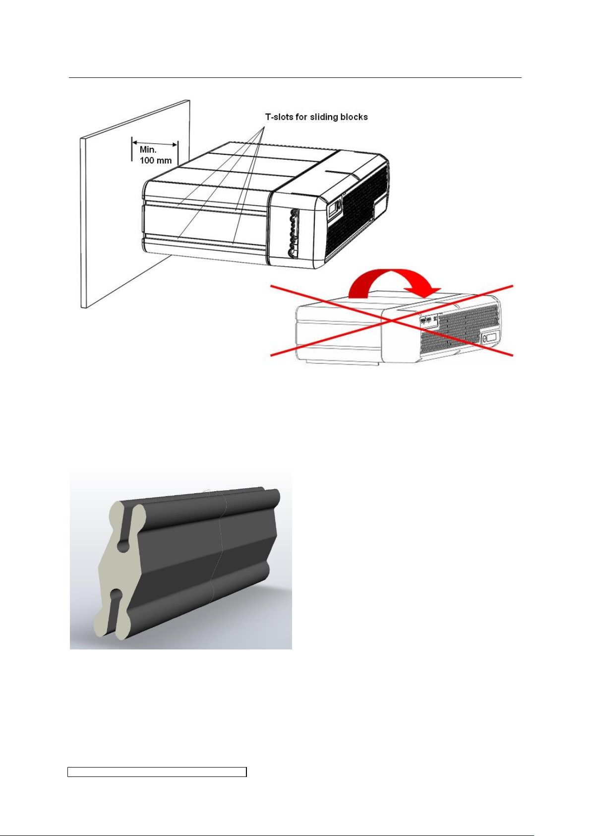
The ELC may only be installed as described in 3.1.1 and in 3.1.2, allowing for at
least the minimum spacing as shown in Fig. 3.
Horizontal mounting upside down is not allowed. All vertical mounting
orientations are possible.
The ELC should not be mounted in the immediate proximity of sensitive electronic
equipment. An appropriate distance must be maintained to scatter field
transformers or other inductors.
The ELC is equipped with built-in fans to ensure forced air cooling. Air ducts and
optional filters must be designed to allow the air flow described in chapter 6. The
ambient temperature must not exceed the values described in chapter 6. The
ambient temperature is measured by the ELC and will be stored within the
internal error memory.
3 Installation
3.1 Mounting of casing
3.1.1 Mounting of single ELC
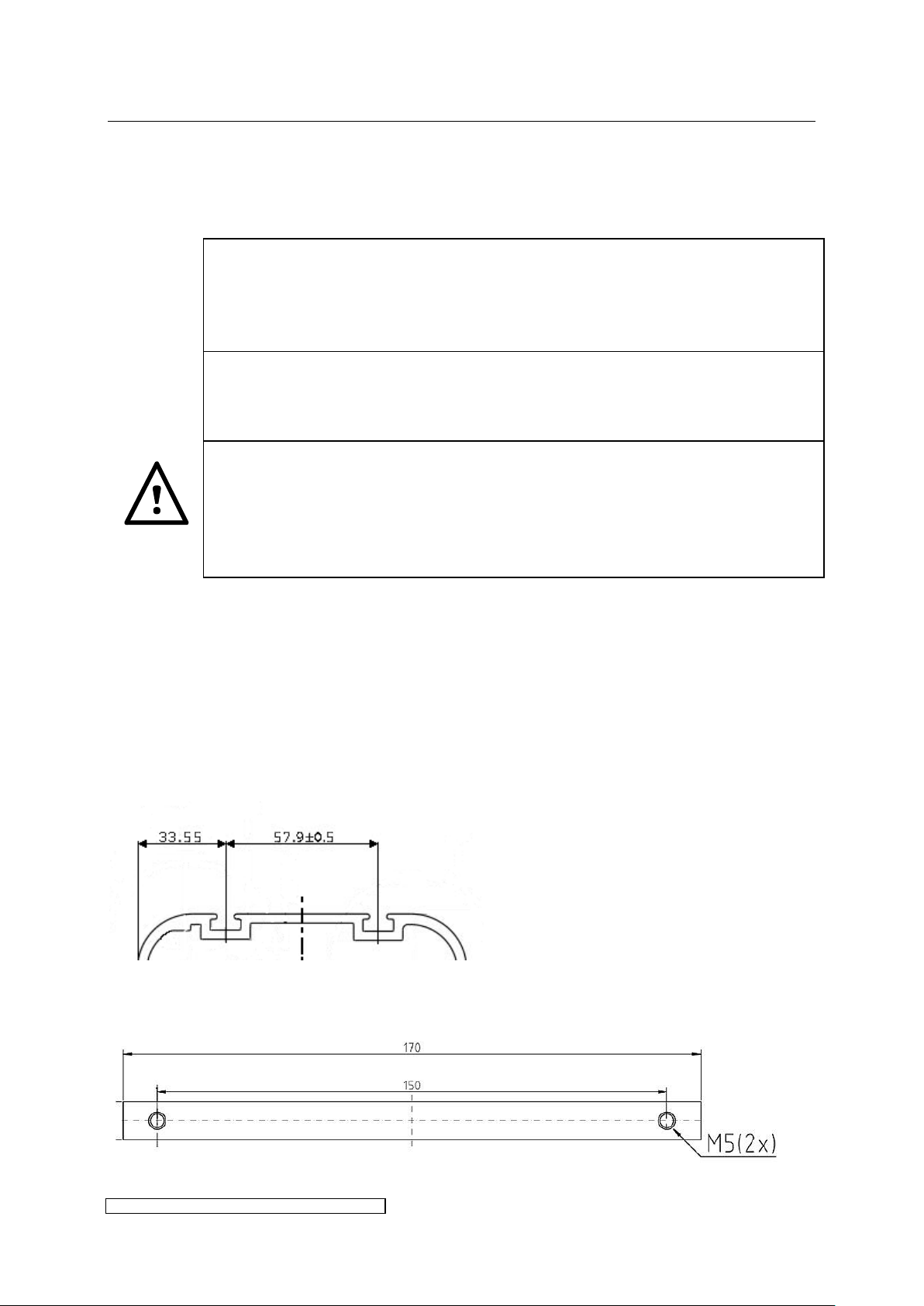
The side surfaces of the housing contain 2 T-slots each. Fig. 1 indicates the relative interspace
of the two T-slots and distance to the outer face of the housing. The T-slots are suitable for
sliding blocks 6mm groove, M5 by Bosch Rexroth, as well as for sliding profiles (see Fig. 2) ,
the latter applicable for X6 and higher power, both available as accessories. Fig. 3 shows the
horizontal mounting orientation including the minimum spacing at the back of the ELC.
Alternatively the ELC may be mounted flush with the rear panel if a cut out for the ventilation
is ensured.
Fig. 1: Position of the T-slots
Fig. 2: Sliding profile
3 Installation page 5
ELC X-Series-V1.5-06.18-GB subject to technical alterations
Fig. 3: Mounting of the ELC, horizontal orientation
3.1.2 Mounting in a stack
Up to 12 ELC may be mounted on top of each other. To fasten the ballasts onto each other a
custom-built stacking connector has to be used (available as accessories):
Fig. 4: Stacking connector for stack mounting
3 Installation page 6
ELC X-Series-V1.5-06.18-GB subject to technical alterations
Cable gasket
X100
X600
X2
X1
X3
X805
X806
3.2 Connection
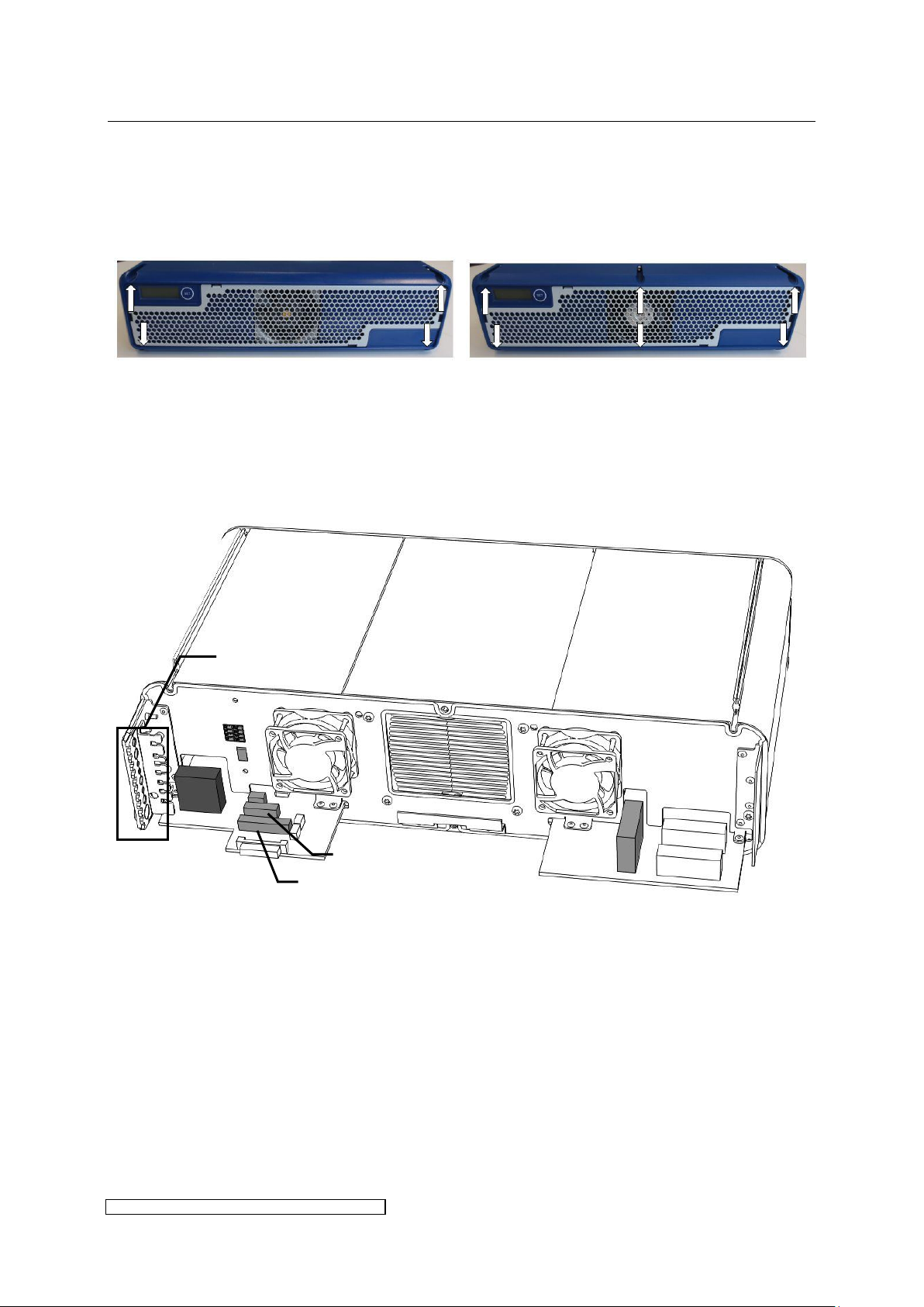
To gain access to the electrical contacts the front hood has to be removed. Loosen the
screwing (according to model 4 or 6 x TX20-screw) and detach the front hood.
The following paragraphs describe the electrical connections.
3.2.1 Connection overview of ballast types X4 – X8
Fig. 5: Overview of electrical connections X4-X8
3 Installation page 7
ELC X-Series-V1.5-06.18-GB subject to technical alterations
Cable gasket
Cable
diameter
Connector
designation
Function
Connector
no. of pins
Connector
type eta
ID.:
Cable
length
(gasket to
connector)
Plug
contact
7.5mm
±5%
X3
Bus out
(T-
coupler)
3
9546
120mm
blank
wire or
ferrule
9.3mm ±
5%
X600 (1, 3)
Lamp
output
3
9532
155mm
blank
wire or
ferrule
4.9mm ±
5%
X600 (2)
PE
5.2mm ±
5%
X806
Control
7
9535
130mm
ferrule
7.5mm ±
5%
X1
Bus in
4
9545
120mm
blank
wire or
ferrule
6.7mm ±
5%
X805
Control
11
9536
130mm
ferrule
7.5mm ±
5%
X2
Bus out
4
9545
120mm
blank
wire or
ferrule
12.2mm ±
5%
X100
Mains
input (2 x
Phase, 2 x
PE)
4
9531
490mm
blank
wire or
ferrule
3.2.2 Profile of the cable gasket X4 – X8
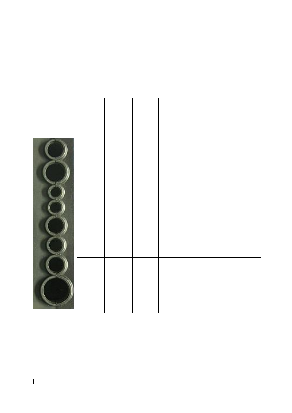
The IP protection level given in chapter 6 is only guaranteed if every cable’s lead-in is
completely sealed.
For this purpose the following preconditions have to be fulfilled:
Use cables of the nominal diameters given in Table 1.
Table 1: Cable connection parameters X4-X8
3 Installation page 8
ELC X-Series-V1.5-06.18-GB subject to technical alterations
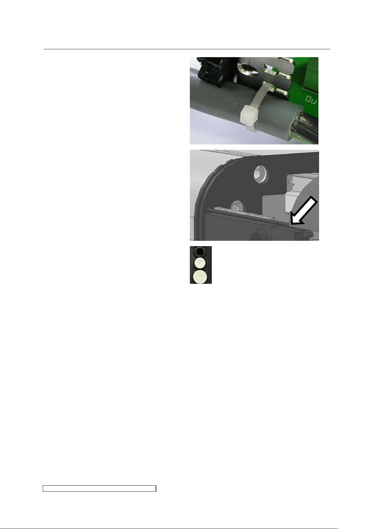
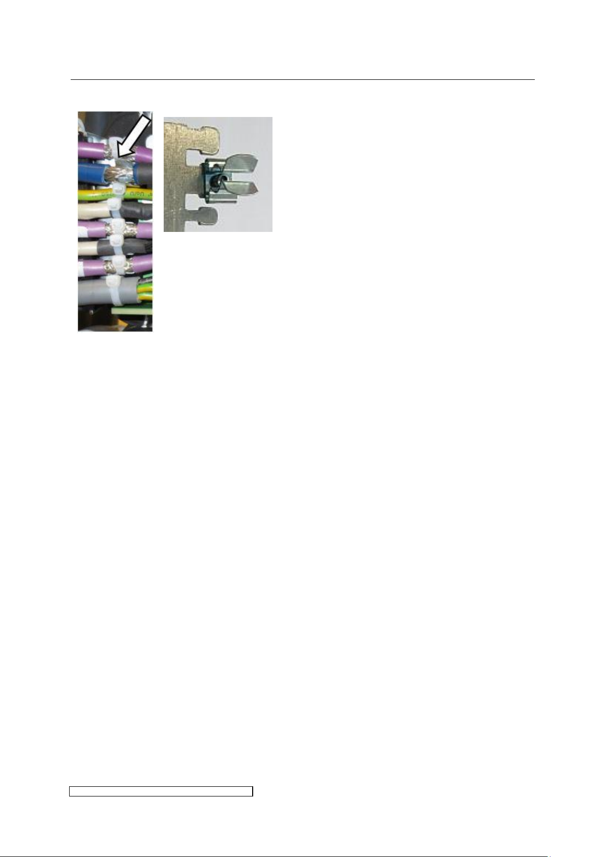
Place the cables into the rubber
surrounds and fix them onto the clamp
with cable straps:
Slide the front hood onto the sealing lip
and pay attention to a tight connection of
the front hood.
If the control concept requires fewer
control and bus cables the holes of the
rubber surround have to be sealed with
blank plugs (available as accessories):
3 Installation page 9
ELC X-Series-V1.5-06.18-GB subject to technical alterations
The lamp feeder cable shielding must be connected to the ELC at the designated
shield clamp, see paragraph 3.2.9.
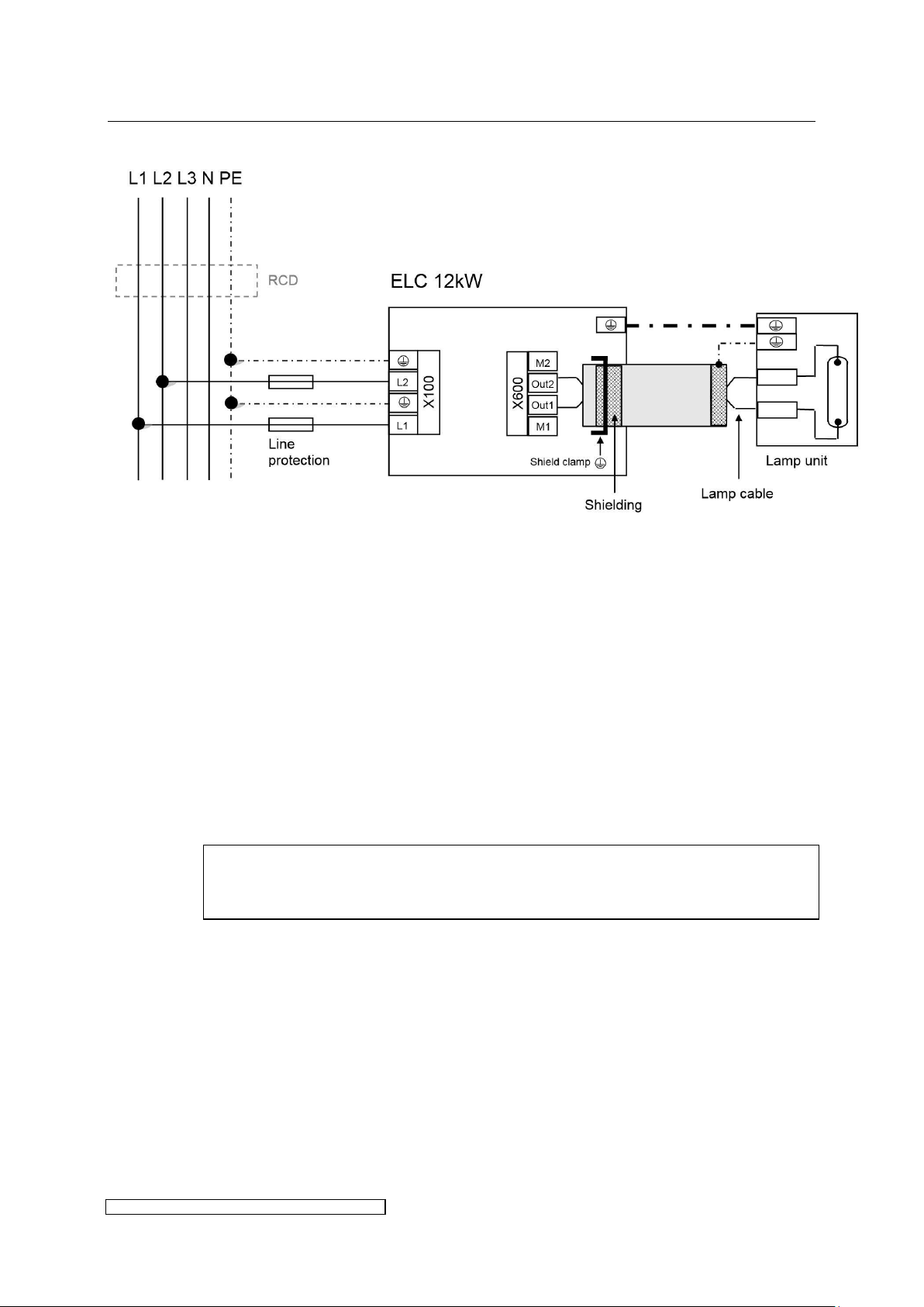
3.2.3 Overview power connections X4 – X8
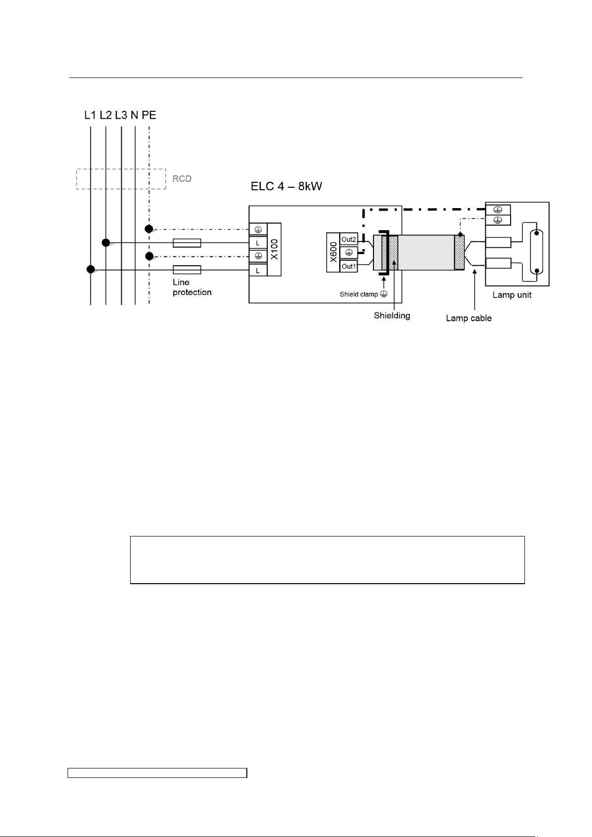
Fig. 6: Power connection X4-X8
Fig. 6 shows the electrical wiring. Please consider the following aspects:
Voltage balancing: on installing several ELCs the ballasts have to be equally distributed on all
phases (e.g. 1st ballast L1/L2, 2nd ballast L2/L3, 3rd ballast L3/L1 etc.).
Protective conductors: to ground the ballast it is strongly recommended to connect to X100 at
least one PE-line with a cross section of 10mm² or two PE-lines with nominal cross section of
the mains supply lines.
Cut-Out and loop impedance: The installation of an automatic cut-out is required for line
protection. It is necessary to check the loop impedance afterwards.
Using an RCD: if a RCD is required we recommend a RCD type B. When using a RCD consider
the leakage current given in chapter 6.
Shielding:
If desired, the shielding can also be connected to the lamp unit.
3 Installation page 10
ELC X-Series-V1.5-06.18-GB subject to technical alterations
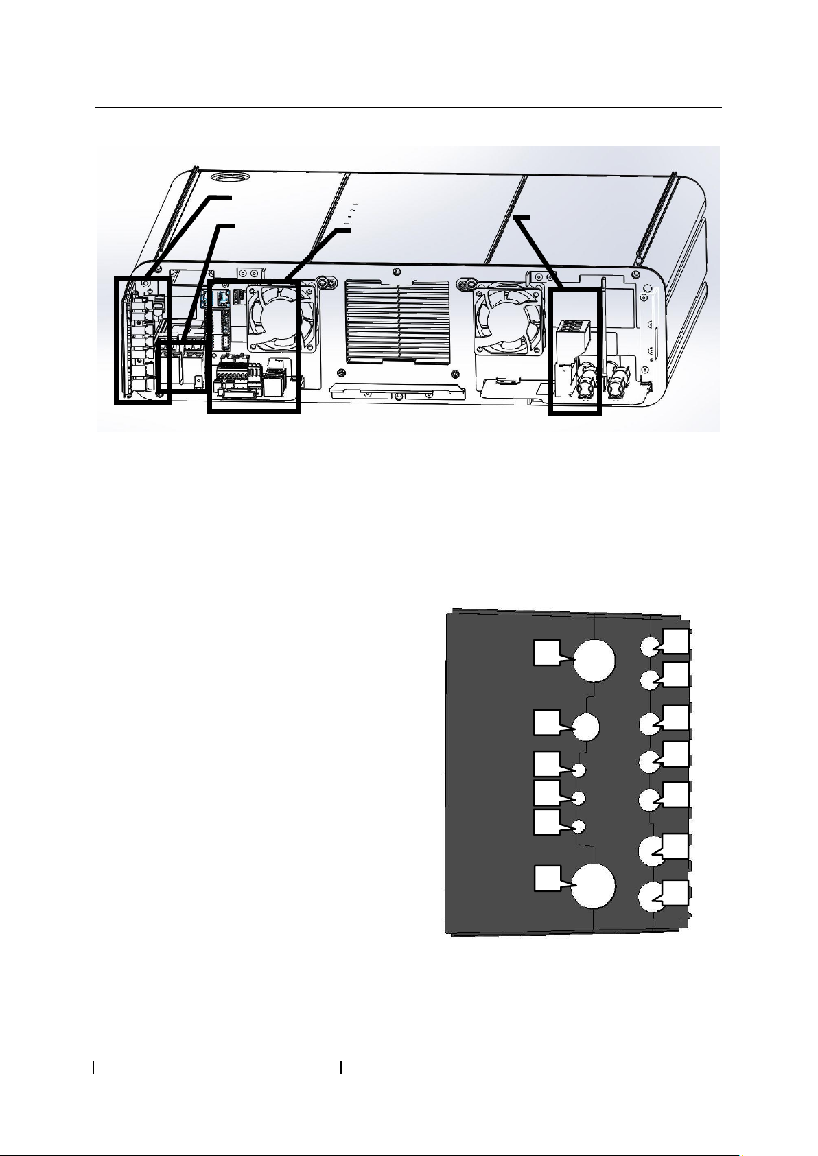
Use cables of the nominal diameters given
in Table 2 on page 11. For the mapping to
the lead-ins in the cable gasket see Fig. 8.
The gasket provides alternative lead-ins for
the use of several cable types.
Fig. 8: Profile of the cable gasket X12-X36
Mains connection
Control connections
Lamp
connection
Cable gasket
4
3
2
1
5
6 7 8
9
10
11
12
13
3.2.4 Connection overview of ballast types X12 – X36
Fig. 7: Overview of electrical connections X12-X36
3.2.5 Overview profile of the cable gasket X12 – X36
The IP protection level given in chapter 6 is only guaranteed if every cable’s lead-in is
completely sealed.
For this purpose the following preconditions have to be fulfilled:

3 Installation page 11
ELC X-Series-V1.5-06.18-GB subject to technical alterations
Position
(see
Fig. 8)
Cable
diameter
Connector
designation
Function
Connector
no. of pins
Connector
type eta
ID.:
Cable
length
(gasket to
connector)
Plug contact
1
6.8mm ±
5%
X806
Control
7
9535
130mm
ferrule, stripping
length 7mm
2
6.8mm ±
5%
X805
Control
11
9536
130mm
ferrule, stripping
length 7mm
3
7.5mm
±5%
X3
Bus out
(T-coupler)
3
9546
120mm
blank wire or
ferrule, stripping
length 9mm
4
7.5mm ±
5%
X1
Bus in
4
9545
120mm
blank wire or
ferrule, stripping
length 9mm
5
7.5mm ±
5%
X2
Bus out
4
9545
120mm
blank wire or
ferrule, stripping
length 9mm
6
9.8mm ±
5%
X806
Control
(alternative)
7
9535
130mm
ferrule, stripping
length 7mm
7
9.8mm ±
5%
X805
Control
(alternative)
11
9536
130mm
ferrule, stripping
length 7mm
8
13.5mm ±
5%
X600 (1, 3)
Lamp
output
2 - 155mm
blank wire or
ferrule stripping
length 15mm,
direct connection
on board
9
9.3mm ±
5%
X600 (1, 3)
Lamp
output
(alternative)
2 - 155mm
blank wire or
ferrule stripping
length 15mm,
direct connection
on board
10
5.4mm ±
5%
X600 (2)
PE 1 -
155mm
Blade receptacle
6.3mm, direct
connection on
board
X100 (1)
Mains input
PE
(alternativ)
1
9531
490mm
blank wire or
ferrule, stripping
length 18mm
11
5.4mm ±
5%
X100 (2)
Mains input
phase
(alternativ)
1
(9531)
490mm
blank wire or
ferrule, stripping
length 18mm
12
5.4mm ±
5%
X100 (4)
Mains input
phase
(alternativ)
1
(9531)
490mm
blank wire or
ferrule, stripping
length 18mm
13*
12.0mm ±
5%
X100
Mains input
(2 x phase, 2
x PE)
4
9531
490mm
blank wire or
ferrule, stripping
length 18mm
14.6mm ±
5%
Table 2: Cable connection parameters X12-X36
3 Installation page 12
ELC X-Series-V1.5-06.18-GB subject to technical alterations
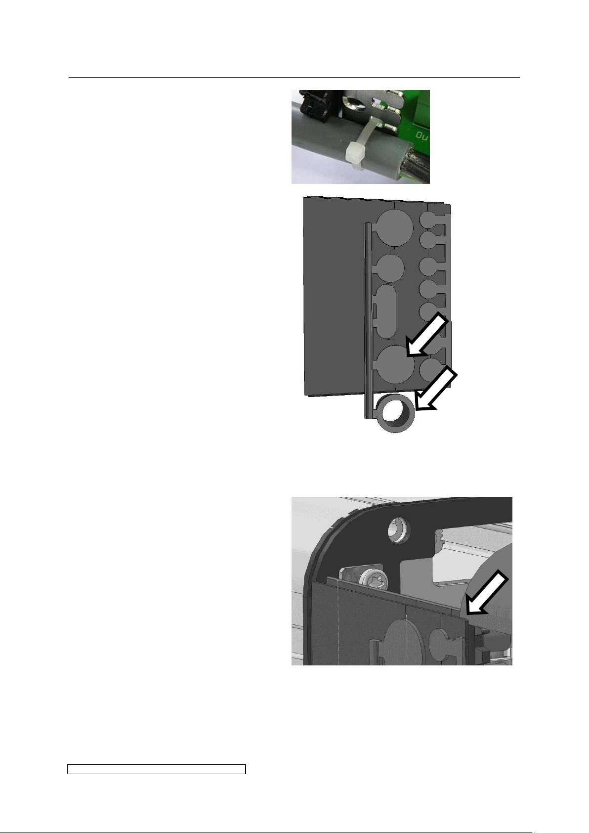
Place the cables into the rubber
surrounds and fix them onto the clamp
with cable straps:
On delivery the lead-ins are sealed with
blank plugs (see Fig. 9). These can be
removed as required.
Note to the lead-in of mains supply (cf.
position 13 in Fig. 8 and Table 2):
When using mains supply cables of
maximally possible diameter the
according blank plug of the blank plug
line has to be removed.
In case of smaller diameter use the
sealing ring of Fig. 9 and put the cable
through it.
Fig. 9: Blank plug line with sealing ring for ELC
X12-X36
Slide in the front hood centrically into
the sealing lips and pay attention to a
tight connection of the front hood.
3 Installation page 13
ELC X-Series-V1.5-06.18-GB subject to technical alterations
The lamp feeder cable shielding must be connected to the ELC at the designated
shield clamp, see paragraph 3.2.9.
3.2.6 Overview power connections X12
Fig. 10: Power connection X12
Please consider the following aspects:
Voltage balancing: on installing several ELCs the ballasts have to be equally distributed on all
phases (e.g. 1st ballast L1/L2, 2nd ballast L2/L3, 3rd ballast L3/L1 etc.).
Protective conductors: to ground the ballast it is strongly recommended to connect to X100 at
least one PE-line with a cross section of 10mm² or two PE-lines with nominal cross section of
the mains supply lines.
Cut-Out and loop impedance: The installation of an automatic cut-out is required for line
protection. It is necessary to check the loop impedance afterwards.
Using a RCD: if a RCD is required we recommend a RCD type B. When using a RCD consider
the leakage current given in chapter 6.
Shielding:
If desired, the shielding can also be connected to the lamp unit.
3 Installation page 14
ELC X-Series-V1.5-06.18-GB subject to technical alterations
The lamp feeder cable shielding must be connected to the ELC at the designated
shield clamp, see paragraph 3.2.9.
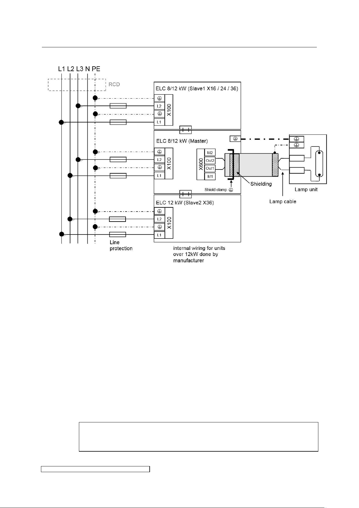
3.2.7 Overview power connections X16 – X36
Fig. 11: Power connections X16 – X36
Please consider the following aspects:
Connecting the lines: The Slave module has only to be connected to power supply including
PE on X100. The Master module has to be connected to power supply and PE on X100, and
additionally to all bus-, control- and lamp cables.
Voltage balancing: on installing several ELCs the ballasts have to be equally distributed on all
phases (e.g. 1st ballast L1/L2, 2nd ballast L2/L3, 3rd ballast L3/L1 etc.).
Protective conductors: to ground the ballast it is strongly recommended to connect to X100 at
least one PE-line with a cross section of 10mm² or two PE-lines with nominal cross section of
the mains supply lines.
Cut-Out and loop impedance: The installation of an automatic cut-out is required for line
protection. It is necessary to check the loop impedance afterwards.
Using an RCD: if a RCD is required we recommend a RCD type B. When using a RCD consider
the leakage current given in chapter 6.
Shielding:
If desired, the shielding can also be connected to the lamp unit.
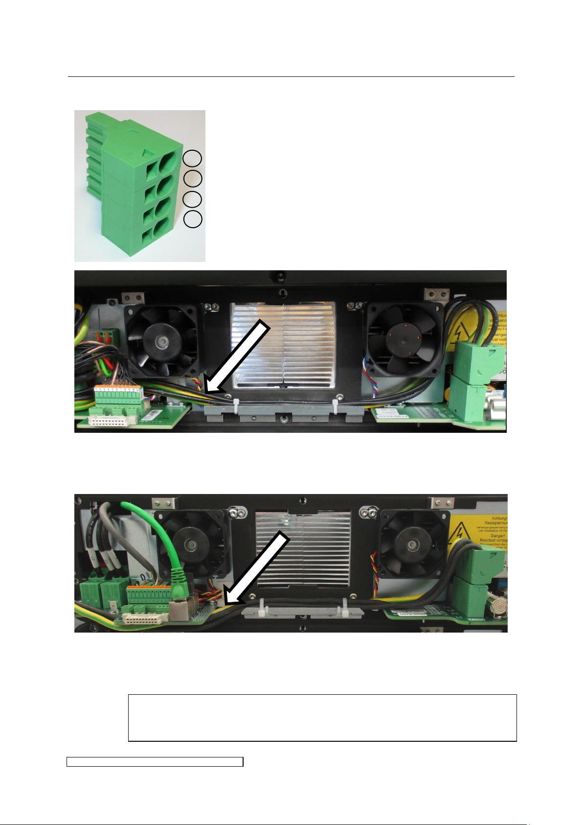
3 Installation page 15
ELC X-Series-V1.5-06.18-GB subject to technical alterations
X4-X8: Fix the mains connection cables within the cable holder beneath the heat sink with
cable straps. The cables have to be laid behind the control connectors to reach the cable
gasket.
X12-X36: Fix the mains connection cables within the cable holder with cable straps. The
cables have to be laid beneath the board to reach the cable gasket.
Pay attention not to pinch the cables when closing the front hood.
L1
PE
L2
PE
3.2.8 X100: Mains connection
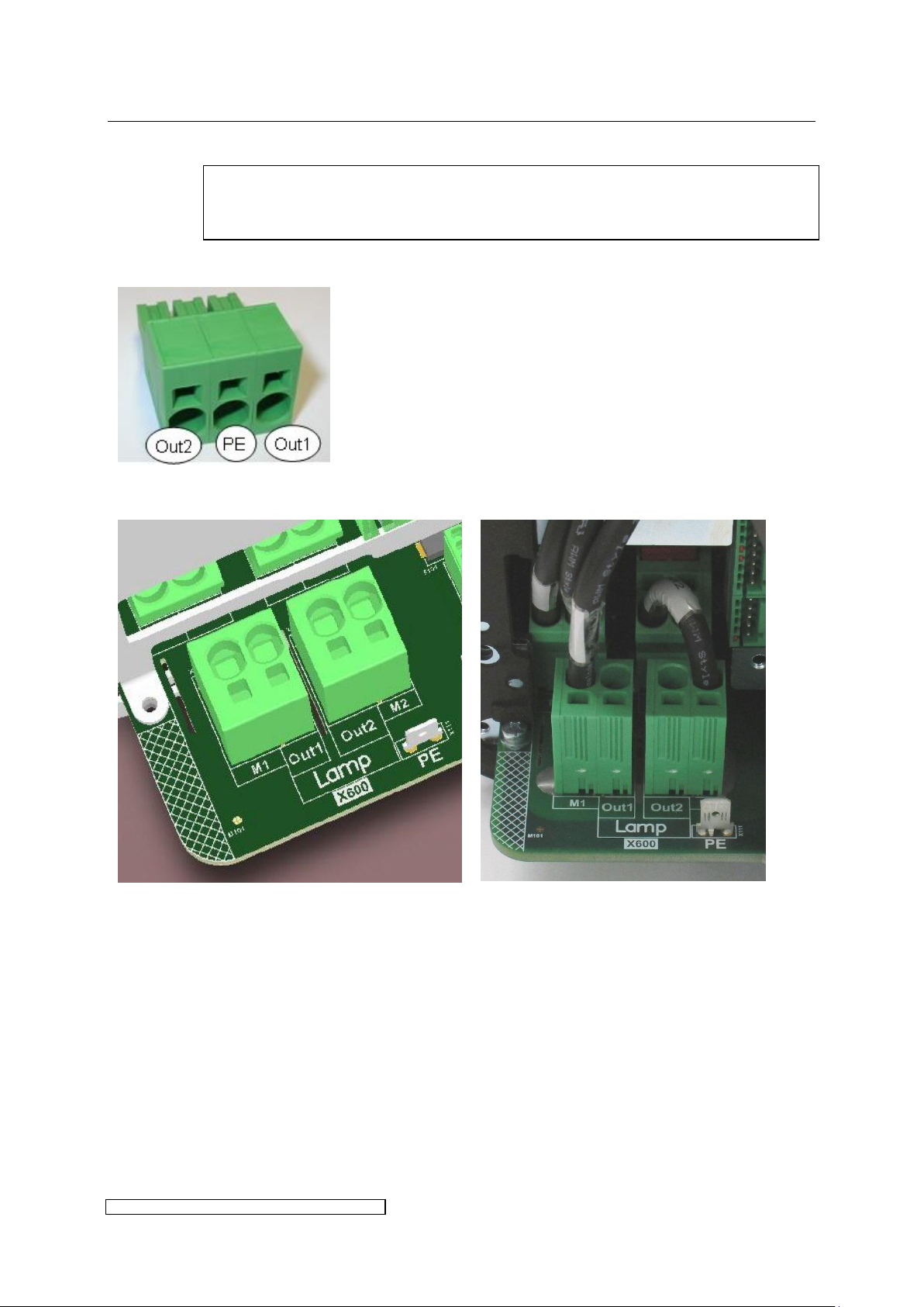
3 Installation page 16
ELC X-Series-V1.5-06.18-GB subject to technical alterations
The lamp feeder cable must correspond with the cable parameters described in
chapter 6.
X4-X8 use a plug for the connection:
PE may be collected of pin 2 of the
connector in order to earth the lamp
housing. If the lamp-housing is earthed
otherwise, the pin has to be left open.
X12-X36 lamp feeder cables are connected directly on the board:
Schematic of lamp connection X12-36
Example of X24 master board (delivery
state)
Connector order:
M1 (reserved for internal wiring) - Out1 – Out 2 - M2 (reserved for internal wiring)
PE
3.2.9 X600: Connecting the lamp feeder cable
3 Installation page 17
ELC X-Series-V1.5-06.18-GB subject to technical alterations
Laying in cable gasket:
The shield clamp is provided for the shield
of the lamp feeder cable. For this cable the
cable strap is not necessary.
The lamp feeder cable between the switch cabinet and lamp assembly must be laid in a
protected way. For the correct installation of the lamp assembly and lamp please observe
the corresponding manufacturer’s instructions.
3 Installation page 18
ELC X-Series-V1.5-06.18-GB subject to technical alterations
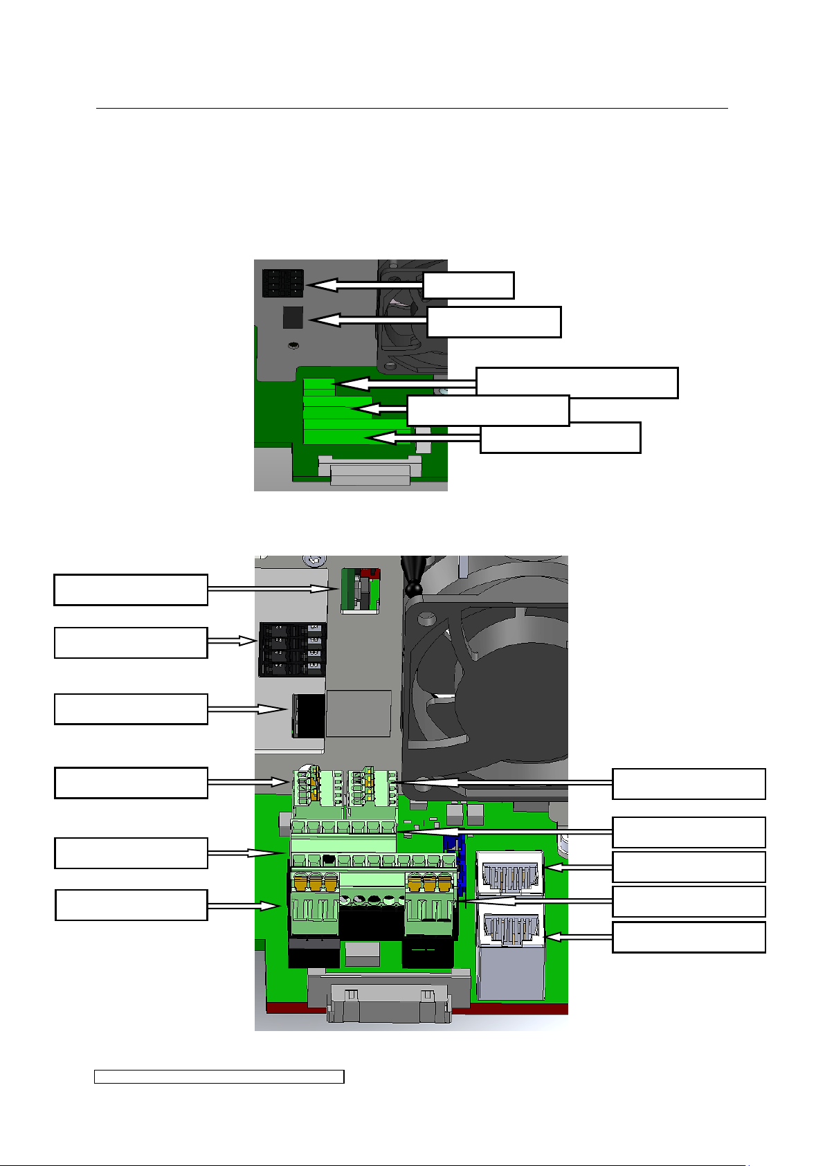
X300: Service USB
X1/X2: BUS
X122: int. connection
X604: int. connection
X123: int. connection
X605: int. connection
X805: Control cable
X102: not in use
X806: Control cable
X3: BUS T-coupler
X104: Service PFC
X3: BUS T-coupler
X808: Service interface
X805: Control cable
X806: Control cable
3.2.10 Overview of control and bus connections
The control cables are connected by means of the plug connections available as accessories.
All control circuits must be earthed upon installation.
The connector positions are shown in Fig. 12 or Fig. 13 and will be explained in the following
tables.
Fig. 12: Control and bus connections X4-X8
Fig. 13: Control and bus connections X12-X24
3 Installation page 19
ELC X-Series-V1.5-06.18-GB subject to technical alterations
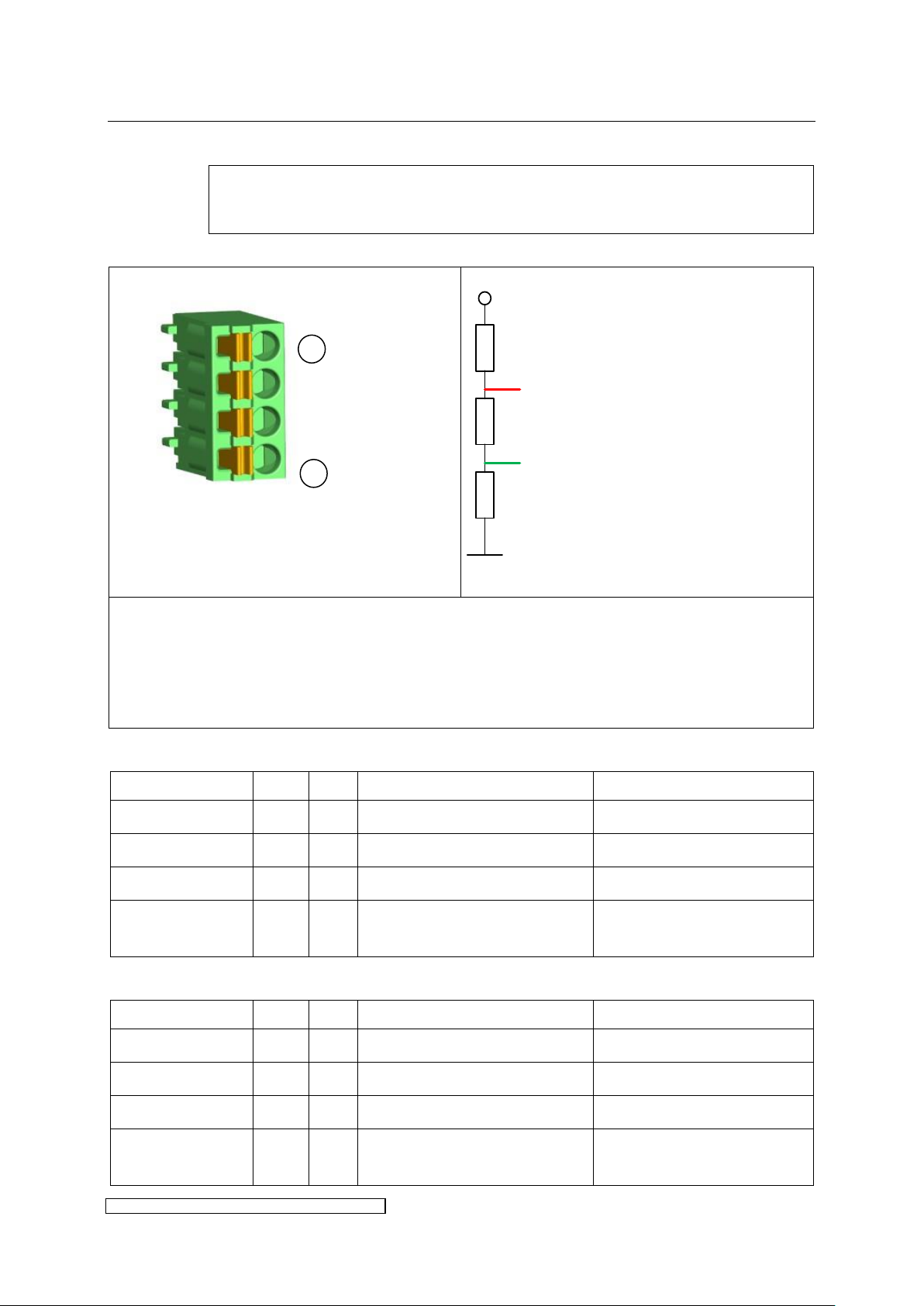
To ensure secure data transmission the use of a BUS-specific cable is
recommended.
Connector pin assignment:
Fig. 14: BUS-termination
The shield has to be put on Pin 1 = BUS GND. Insulate with shrunk-on sleeve.
The contacts of X1 and X2 are internally connected.
The RS485 BUS has to be terminated at the end of the BUS line according to PROFIBUS-Norm
IEC 61158 (also see Fig. 14). On the last ballast one of the connectors X1 or X2 will be left
open and can be used for the termination (available as accessories).
Designation
X1
X2
Description
technical
BUS GND
X1.1
X2.1
GND insulated for BUS
Shield connection BUS
BUS A
X1.2
X2.2
Data line BUS A
Bus signal A
BUS B
X1.3
X2.3
Data line BUS B
Bus signal B
BUS VCC
X1.4
X2.4
external supply voltage 5V
insulated for BUS
+5V DC insulated, output for
terminator only
Designation
X1
X2
Description
technical
BUS GND
X1.1
X2.1
GND insulated for MODBUS
Shield connection MODBUS
BUS A
X1.2
X2.2
Data line A
Inverting In-/Output
BUS B
X1.3
X2.3
Data line B
None inverting In-/Output
BUS VCC
X1.4
X2.4
external supply voltage 5V
insulated for Bus-termination
+5V DC insulated, output for
terminator only
5V
A
B
390 Ω
390 Ω
220 Ω
1
4
3.2.11 X1 / X2: BUS connections
Pin assignment X1 / X2 for BUS:
Pin assignment X1 / X2 for MODBUS:
3 Installation page 20
ELC X-Series-V1.5-06.18-GB subject to technical alterations
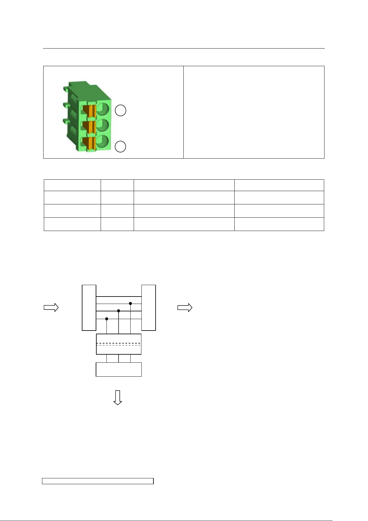
Connector pin assignment:
The shield has to be put on Pin 1 = BUS GND.
Insulate with shrunk-on sleeve.
Designation
Number
Description
technical
BUS GND
X3.1
GND insulated for BUS
Shield connection BUS
BUS A
X3.2
Data line BUS A
Bus signal A
BUS B
X3.3
Data line BUS B
Bus signal B
1.4
1.3
1.2
1.1
2.4
2.3
2.2
2.1
3.1 3.2 3.3
X3
X1
X2
galvanic isolation
T-coupler
1
3
3.2.12 X3: BUS T-coupler
Pin assignment X3:
The T-coupler connection may be used as a BUS repeater. Via the T-coupler (see Fig. 15) the
BUS-data lines A and B as well as their reference ground may be applied (galvanically
insulated) to another slave device. The T-coupler already contains a termination according to
Fig. 14. Solely a bitrate of 500kbit is applicable. If the T-coupler connection is not required X3
may be left open.
Fig. 15: Schematic of the T-coupler connection
X3 is not active in MODBUS control mode.
 Loading...