

eta plus ELC N12, ELC NE32D, ELC N32, ELC NE32, ELC NE12 Technical Documentation Manual
...
o
ur name is our principle
UV-
TECHNOLOGY
Technical Documentation
®
ELC
ELC
ELC
®
N12 - ELC® N32 /
®
NE12 - ELC® NE32 /
NE12D - ELC® NE32D
GB
eta plus electronic gmbh
Lauterstraße 29, 72622 Nürtingen, Telefon +49 7022 6002-80, Fax +49 7022 65854, E-mail: info@eta-uv.de, www.eta-uv.de
Eingetragen unter HRB 724321 AG Stuttgart, USt.-Id.-Nr. DE 146267800, Geschäftsleitung: Uwe Uhlemann, Dr. Markus Roth

ELC® („Electronic Lamp Control“) is a registered trademark of
IST Metz GmbH.
ELC N12-N32_NE12-NE32_NE12D-NE32D-V1.0-03.17-GB Subject to technical alterations

Safety page 1
Contents
1 Safety ................................................................................................ 3
1.1 Definition of Symbols ................................................................................. 3
1.2 Safety Advice .............................................................................................. 3
1.3 Correct operation ........................................................................................ 4
1.4 Extended use .............................................................................................. 4
2 Description of functions .................................................................. 5
3 Installation ........................................................................................ 6
3.1 Mounting of casing ..................................................................................... 6
3.1.1 Installation position N12, N16, NE12, NE16, NE12D, NE16D ........................ 7
3.1.2 Installation position N22, N32, NE22, NE32, NE22D, NE32D ........................ 9
3.2 Connection ................................................................................................ 11
3.3 Control current connections .................................................................... 16
3.3.1 Series N12 – N32 and NE12 – NE32 ........................................................... 16
3.3.2 Series NE12D – NE32D .............................................................................. 16
3.4 Explanations of the control functions for ELC ....................................... 18
3.4.1 Release relay .............................................................................................. 18
3.4.2 Control input START ................................................................................... 18
3.4.3 Setting lamp power ...................................................................................... 18
3.4.4 Table: lamp power ....................................................................................... 19
3.4.5 Earth fault control ........................................................................................ 20
4 Operation of ELC ........................................................................... 22
4.1 Initial operation ......................................................................................... 22
4.2 Switching on the ELC ............................................................................... 22
4.3 Switching on the lamp .............................................................................. 22
4.4 Dimming Operation .................................................................................. 23
4.5 Standby Operation .................................................................................... 23
4.6 Switching off the Lamp ............................................................................ 23
5 Troubleshooting ............................................................................ 24
5.1 Repair of ELC ............................................................................................ 24
ELC N12-N32_NE12-NE32_NE12D-NE32D-V1.0-03.17-GB Subject to technical alterations

Safety page 2
6 Technical Data ............................................................................... 25
6.1 General data ELC ...................................................................................... 25
6.2 Type specific data NE12D/NE16D/NE22D/NE32D (nominal
values) ....................................................................................................... 26
6.3 Type specific data NE12/NE16/NE22/NE32 (nominal values) ................ 28
6.4 Type specific data N12/N16/N22/N32 (nominal values) ......................... 30
ELC N12-N32_NE12-NE32_NE12D-NE32D-V1.0-03.17-GB Subject to technical alterations

Safety page 3
☞
1 Safety
1.1 Definition of Symbols
Stop (Stop Danger). This symbol warns of serious danger of severe injury to
persons. It must be strictly observed.
Attention (Warning). This symbol indicates information the non-observance of
which can lead to extensive damage to property. The safety warning must be
strictly observed.
Information. This symbol indicates key information on use. Non-observance can
lead to failure.
1.2 Safety Advice
The ELC must be installed and connected in compliance with existing regulations
and practices. This is e.g. EN 60204-1 in Europe.
Repairs on the ELC may only be carried out by the manufacturer.
The installation and starting up may only be carried out by skilled electricians.
Do not open the ELC before it is disconnected from the mains. BEWARE OF
RESIDUAL VOLTAGE! The unit may still be live up to three minutes after it has
been switched off.
ELC N12-N32_NE12-NE32_NE12D-NE32D-V1.0-03.17-GB Subject to technical alterations
Safety page 4
there is no danger when
The ELC causes a leakage current greater than 3.5 mA!
Safeguarding by means of leakage current protection type A and type AC
according to IEC 60755 is not permitted!
The ELC operates in principle as a frequency converter and is equipped with a
mains filter whose leakage current could activate fuse protection.
Contact to the grounding connector must always be ensured.
Additional measures must be taken to ensure that
touching the appliance. This could be by means of a universal leakage current
protection type B, taking into consideration the increased response threshold, or
by means of an independent equipotential connection
1.3 Correct operation
The ELC is an electrical unit intended to be installed in the switch cabinets of
industrial high-voltage power installations. It is conceived as an electronic ballast
for the operation of lamps intended for this purpose.
Any other use is deemed as misuse. The manufacturer will not assume liability for
damage resulting from misuse.
A pre-requisite for authorised operation of the ELC is the observance of both the
operating and maintenance instructions and the safety advice.
1.4 Extended use
Extended use beyond the operating specifications as stated is not permitted.
The manufacturer will not assume liability if the equipment is used in any other
way. The operator acts at his own risk.
Any operation beyond the scope of the authorised operation is considered to be
misuse.
ELC N12-N32_NE12-NE32_NE12D-NE32D-V1.0-03.17-GB Subject to technical alterations

Description of functions page 5
2 Description of functions
The ELC is an electronic power supply unit for the operation of gas discharge lamps with
electrical properties as described in chapter 6.
In contrast to conventional ballasts (inductive lamp ballast or transformer or transformer with
transductor), the lamp with an electronic ballast is operated with high frequency (approx.
100 kHz). The lamp does not flicker and dimming is infinitely adjustable to a range between
20 % and 100 % of the electric power or to between 15 % and 100 % of the UV radiation
respectively.
Dimming
The possibility of dimming the lamp has two advantages. Firstly the lamp can be switched to
minimum load (standby operation) during longer idle times and energy can thus be saved.
Secondly the optimum lamp power can be determined and adjusted as appropriate.
Power control
The ELC offers a high level of lamp power constancy due to its integrated power control.
Variations in operating voltage of ± 10 % do not affect lamp power.
Ignition device
When the lamp is switched on the ELC initiates trigger pulses to fire the lamp; a separate
ignition device is not required.
Other performance characteristics
• High level of electrical efficiency.
• The potential-free control inputs allow various lamp conditions such as maximum lamp
power, dimming or standby to be set.
• The digital control inputs are designed for control voltages of between 10 and 30 V AC or
DC. Therefore ELC can be easily integrated into the installation’s electric system.
• Lamp current and lamp power are continuously recorded and output as analogous
0-10 V signals.
• The ELC monitors the lamp cables for earth fault.
• The lamp output potential is separated from that of the supply voltage.
• The ELC is both short-circuit proof and safe in open circuit operation at the lamp output.
ELC N12-N32_NE12-NE32_NE12D-NE32D-V1.0-03.17-GB Subject to technical alterations
Installation page 6
60529). Operation without a control cabinet or in a control cabinet with a lower
An appropriate distance must be maintained to scatter field
switch cabinet, the total electrical losses and the external temperature. Please
3 Installation
3.1 Mounting of casing
The ELC must be installed in a control cabinet with at least IP 54 protection (see
EN
degree of protection is not permitted.
It is only permitted to install the appliance in the positions described in 3.1.1 or
3.1.2. When installed vertically, as described in 3.1.1 or 3.1.2, the control
connections must be positioned at the bottom and supply connections at the top.
Installation must allow for the minimum spacing.
The ELC should not be mounted in the immediate proximity of sensitive electronic
equipment.
transformers or other inductors.
The flow of cool air for the ELC must be safeguarded. The ambient temperature
must not exceed the values prescribed in chapter 6.
Ventilation must be provided for the switch cabinet.
The amount of air necessary is determined by the size and positioning of the
consult your switch cabinet manufacturer. For the recommended throughput of air
please see the technical data in chapter 6.
Impure cooling air could affect the functionality of the ELC. This can be avoided
by installing a fine air filter.
ELC N12-N32_NE12-NE32_NE12D-NE32D-V1.0-03.17-GB Subject to technical alterations
Installation page 7
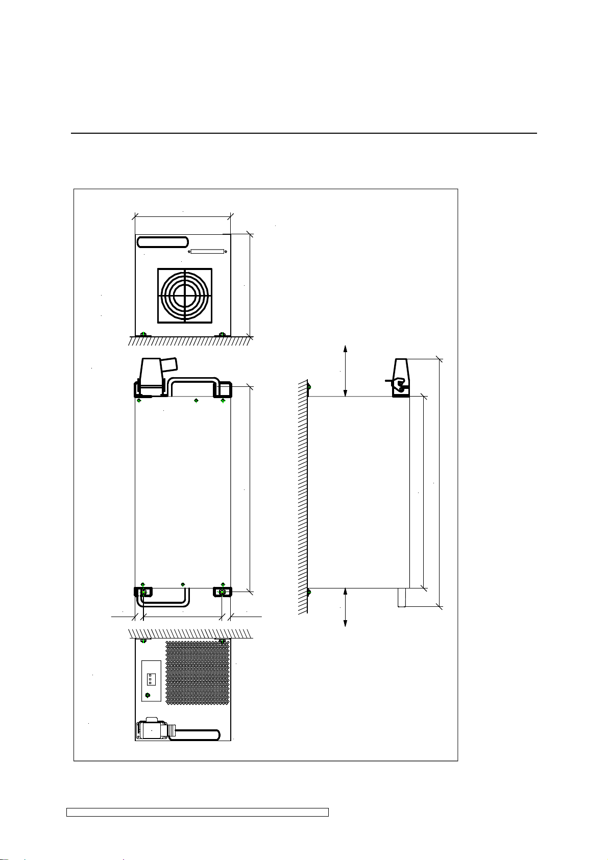
3.1.1 Installation position N12, N16, NE12, NE16, NE12D, NE16D
Vertical installation position
261 mm
Lufteintritt
air entrance
Steckerleiste für Steuersignale
control connector
Oben
top
263,5 mm
min. 150
540 mm
650 mm
501 mm
31 mm
Netzanschluß
line input
Lampenstecker
lampconnection
200 mm
31 mm
Luftaustritt
air exhaust
min. 150
Fig. 1: Assembly of the ELC 12-16kW, vertical installation position (all dimensions in mm).
ELC N12-N32_NE12-NE32_NE12D-NE32D-V1.0-03.17-GB Subject to technical alterations
Installation page 8
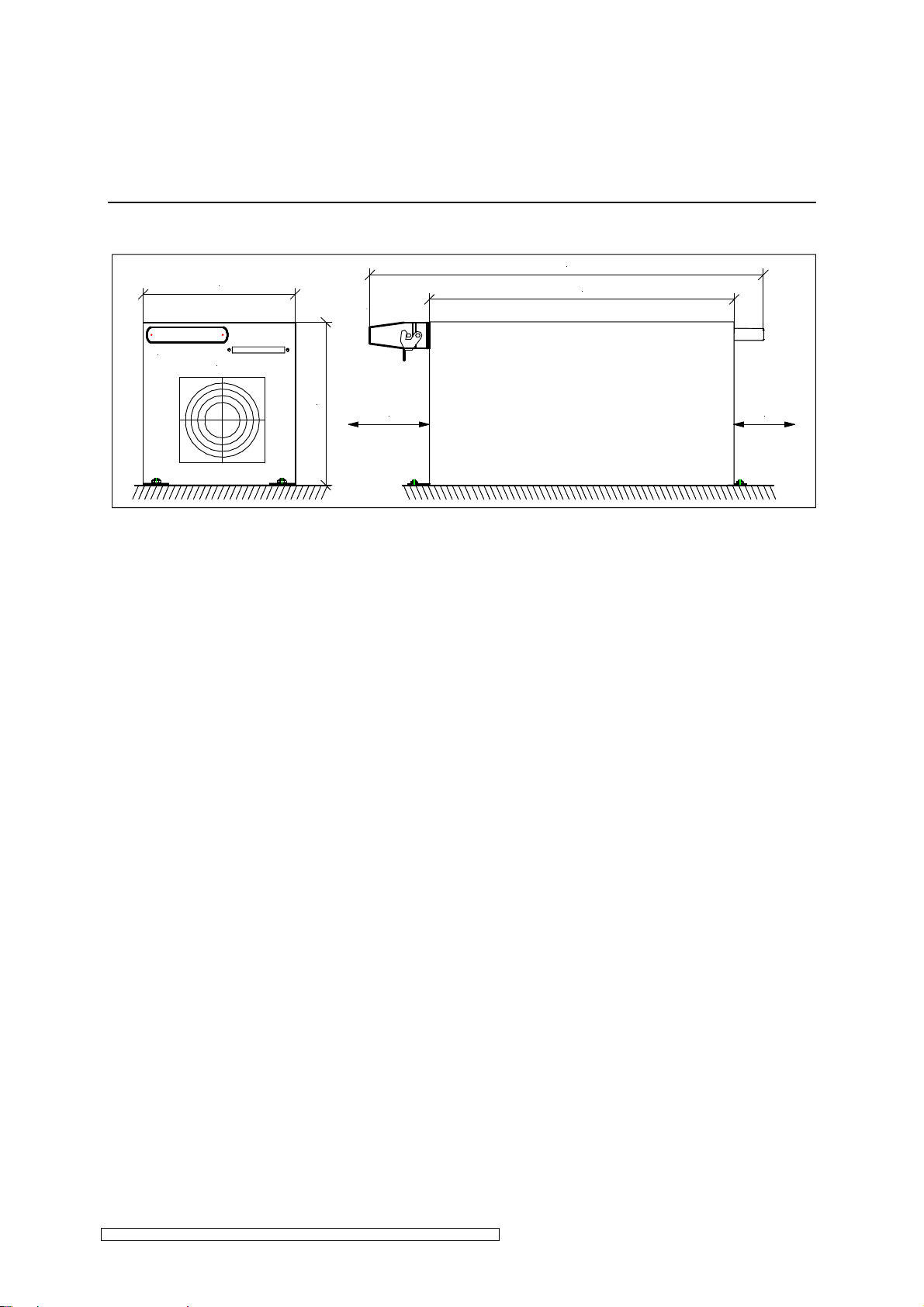
Horizontal installation position
650 mm
261 mm
501 mm
Steckerleiste für Steuersignale
control connector
263,5 mm
min. 150
min. 150
Fig. 2: Assembly of the ELC 12-16kW, horizontal installation position (all dimensions in mm).
ELC N12-N32_NE12-NE32_NE12D-NE32D-V1.0-03.17-GB Subject to technical alterations
 Loading...