

eta plus ELC N12, ELC NE32D, ELC N32, ELC NE32, ELC NE12 Technical Documentation Manual
...Page 1
o
ur name is our principle
UV-
TECHNOLOGY
Technical Documentation
®
ELC
ELC
ELC
®
N12 - ELC® N32 /
®
NE12 - ELC® NE32 /
NE12D - ELC® NE32D
GB
eta plus electronic gmbh
Lauterstraße 29, 72622 Nürtingen, Telefon +49 7022 6002-80, Fax +49 7022 65854, E-mail: [email protected], www.eta-uv.de
Eingetragen unter HRB 724321 AG Stuttgart, USt.-Id.-Nr. DE 146267800, Geschäftsleitung: Uwe Uhlemann, Dr. Markus Roth
Page 2

ELC® („Electronic Lamp Control“) is a registered trademark of
IST Metz GmbH.
ELC N12-N32_NE12-NE32_NE12D-NE32D-V1.0-03.17-GB Subject to technical alterations
Page 3

Safety page 1
Contents
1 Safety ................................................................................................ 3
1.1 Definition of Symbols ................................................................................. 3
1.2 Safety Advice .............................................................................................. 3
1.3 Correct operation ........................................................................................ 4
1.4 Extended use .............................................................................................. 4
2 Description of functions .................................................................. 5
3 Installation ........................................................................................ 6
3.1 Mounting of casing ..................................................................................... 6
3.1.1 Installation position N12, N16, NE12, NE16, NE12D, NE16D ........................ 7
3.1.2 Installation position N22, N32, NE22, NE32, NE22D, NE32D ........................ 9
3.2 Connection ................................................................................................ 11
3.3 Control current connections .................................................................... 16
3.3.1 Series N12 – N32 and NE12 – NE32 ........................................................... 16
3.3.2 Series NE12D – NE32D .............................................................................. 16
3.4 Explanations of the control functions for ELC ....................................... 18
3.4.1 Release relay .............................................................................................. 18
3.4.2 Control input START ................................................................................... 18
3.4.3 Setting lamp power ...................................................................................... 18
3.4.4 Table: lamp power ....................................................................................... 19
3.4.5 Earth fault control ........................................................................................ 20
4 Operation of ELC ........................................................................... 22
4.1 Initial operation ......................................................................................... 22
4.2 Switching on the ELC ............................................................................... 22
4.3 Switching on the lamp .............................................................................. 22
4.4 Dimming Operation .................................................................................. 23
4.5 Standby Operation .................................................................................... 23
4.6 Switching off the Lamp ............................................................................ 23
5 Troubleshooting ............................................................................ 24
5.1 Repair of ELC ............................................................................................ 24
ELC N12-N32_NE12-NE32_NE12D-NE32D-V1.0-03.17-GB Subject to technical alterations
Page 4

Safety page 2
6 Technical Data ............................................................................... 25
6.1 General data ELC ...................................................................................... 25
6.2 Type specific data NE12D/NE16D/NE22D/NE32D (nominal
values) ....................................................................................................... 26
6.3 Type specific data NE12/NE16/NE22/NE32 (nominal values) ................ 28
6.4 Type specific data N12/N16/N22/N32 (nominal values) ......................... 30
ELC N12-N32_NE12-NE32_NE12D-NE32D-V1.0-03.17-GB Subject to technical alterations
Page 5

Safety page 3
☞
1 Safety
1.1 Definition of Symbols
Stop (Stop Danger). This symbol warns of serious danger of severe injury to
persons. It must be strictly observed.
Attention (Warning). This symbol indicates information the non-observance of
which can lead to extensive damage to property. The safety warning must be
strictly observed.
Information. This symbol indicates key information on use. Non-observance can
lead to failure.
1.2 Safety Advice
The ELC must be installed and connected in compliance with existing regulations
and practices. This is e.g. EN 60204-1 in Europe.
Repairs on the ELC may only be carried out by the manufacturer.
The installation and starting up may only be carried out by skilled electricians.
Do not open the ELC before it is disconnected from the mains. BEWARE OF
RESIDUAL VOLTAGE! The unit may still be live up to three minutes after it has
been switched off.
ELC N12-N32_NE12-NE32_NE12D-NE32D-V1.0-03.17-GB Subject to technical alterations
Page 6
Safety page 4
there is no danger when
The ELC causes a leakage current greater than 3.5 mA!
Safeguarding by means of leakage current protection type A and type AC
according to IEC 60755 is not permitted!
The ELC operates in principle as a frequency converter and is equipped with a
mains filter whose leakage current could activate fuse protection.
Contact to the grounding connector must always be ensured.
Additional measures must be taken to ensure that
touching the appliance. This could be by means of a universal leakage current
protection type B, taking into consideration the increased response threshold, or
by means of an independent equipotential connection
1.3 Correct operation
The ELC is an electrical unit intended to be installed in the switch cabinets of
industrial high-voltage power installations. It is conceived as an electronic ballast
for the operation of lamps intended for this purpose.
Any other use is deemed as misuse. The manufacturer will not assume liability for
damage resulting from misuse.
A pre-requisite for authorised operation of the ELC is the observance of both the
operating and maintenance instructions and the safety advice.
1.4 Extended use
Extended use beyond the operating specifications as stated is not permitted.
The manufacturer will not assume liability if the equipment is used in any other
way. The operator acts at his own risk.
Any operation beyond the scope of the authorised operation is considered to be
misuse.
ELC N12-N32_NE12-NE32_NE12D-NE32D-V1.0-03.17-GB Subject to technical alterations
Page 7

Description of functions page 5
2 Description of functions
The ELC is an electronic power supply unit for the operation of gas discharge lamps with
electrical properties as described in chapter 6.
In contrast to conventional ballasts (inductive lamp ballast or transformer or transformer with
transductor), the lamp with an electronic ballast is operated with high frequency (approx.
100 kHz). The lamp does not flicker and dimming is infinitely adjustable to a range between
20 % and 100 % of the electric power or to between 15 % and 100 % of the UV radiation
respectively.
Dimming
The possibility of dimming the lamp has two advantages. Firstly the lamp can be switched to
minimum load (standby operation) during longer idle times and energy can thus be saved.
Secondly the optimum lamp power can be determined and adjusted as appropriate.
Power control
The ELC offers a high level of lamp power constancy due to its integrated power control.
Variations in operating voltage of ± 10 % do not affect lamp power.
Ignition device
When the lamp is switched on the ELC initiates trigger pulses to fire the lamp; a separate
ignition device is not required.
Other performance characteristics
• High level of electrical efficiency.
• The potential-free control inputs allow various lamp conditions such as maximum lamp
power, dimming or standby to be set.
• The digital control inputs are designed for control voltages of between 10 and 30 V AC or
DC. Therefore ELC can be easily integrated into the installation’s electric system.
• Lamp current and lamp power are continuously recorded and output as analogous
0-10 V signals.
• The ELC monitors the lamp cables for earth fault.
• The lamp output potential is separated from that of the supply voltage.
• The ELC is both short-circuit proof and safe in open circuit operation at the lamp output.
ELC N12-N32_NE12-NE32_NE12D-NE32D-V1.0-03.17-GB Subject to technical alterations
Page 8
Installation page 6
60529). Operation without a control cabinet or in a control cabinet with a lower
An appropriate distance must be maintained to scatter field
switch cabinet, the total electrical losses and the external temperature. Please
3 Installation
3.1 Mounting of casing
The ELC must be installed in a control cabinet with at least IP 54 protection (see
EN
degree of protection is not permitted.
It is only permitted to install the appliance in the positions described in 3.1.1 or
3.1.2. When installed vertically, as described in 3.1.1 or 3.1.2, the control
connections must be positioned at the bottom and supply connections at the top.
Installation must allow for the minimum spacing.
The ELC should not be mounted in the immediate proximity of sensitive electronic
equipment.
transformers or other inductors.
The flow of cool air for the ELC must be safeguarded. The ambient temperature
must not exceed the values prescribed in chapter 6.
Ventilation must be provided for the switch cabinet.
The amount of air necessary is determined by the size and positioning of the
consult your switch cabinet manufacturer. For the recommended throughput of air
please see the technical data in chapter 6.
Impure cooling air could affect the functionality of the ELC. This can be avoided
by installing a fine air filter.
ELC N12-N32_NE12-NE32_NE12D-NE32D-V1.0-03.17-GB Subject to technical alterations
Page 9
Installation page 7
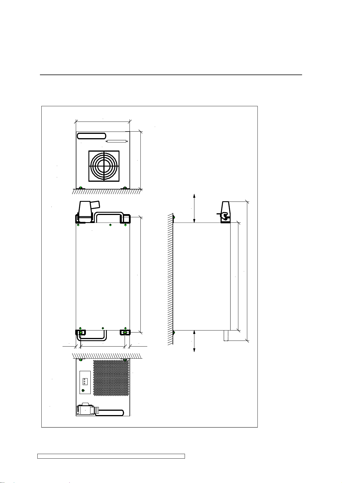
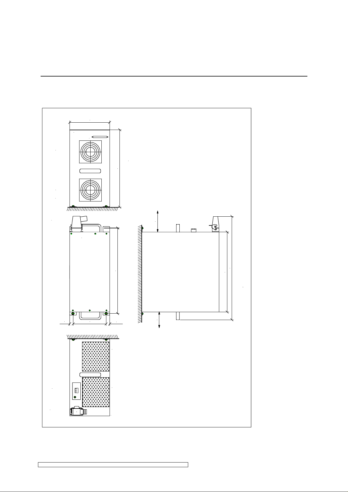
3.1.1 Installation position N12, N16, NE12, NE16, NE12D, NE16D
Vertical installation position
261 mm
Lufteintritt
air entrance
Steckerleiste für Steuersignale
control connector
Oben
top
263,5 mm
min. 150
540 mm
650 mm
501 mm
31 mm
Netzanschluß
line input
Lampenstecker
lampconnection
200 mm
31 mm
Luftaustritt
air exhaust
min. 150
Fig. 1: Assembly of the ELC 12-16kW, vertical installation position (all dimensions in mm).
ELC N12-N32_NE12-NE32_NE12D-NE32D-V1.0-03.17-GB Subject to technical alterations
Page 10
Installation page 8
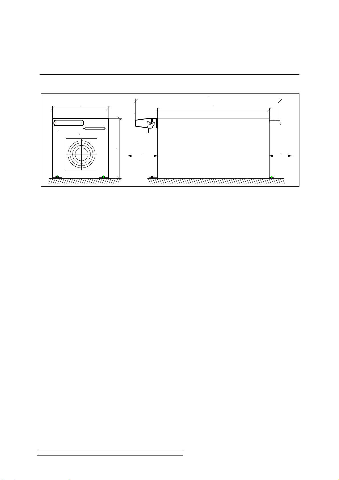
Horizontal installation position
650 mm
261 mm
501 mm
Steckerleiste für Steuersignale
control connector
263,5 mm
min. 150
min. 150
Fig. 2: Assembly of the ELC 12-16kW, horizontal installation position (all dimensions in mm).
ELC N12-N32_NE12-NE32_NE12D-NE32D-V1.0-03.17-GB Subject to technical alterations
Page 11
Installation page 9
3.1.2 Installation position N22, N32, NE22, NE32, NE22D, NE32D
Vertical installation position
261 mm
Steckerleiste für Steuersignale
control connector
Lufteintritt
air entrance
484 mm
Lufteintritt
air entrance
min. 150
Oben
top
650 mm
501 mm
31 mm 31 mm
Netzanschluß
line input
Lampenstecker
lampconnection
200 mm
540 mm
Luftaustritt
air exhaust
Luftaustritt
air exhaust
min. 150
Fig. 3: Assembly of the ELC 22-32kW, vertical installation position (all dimensions in mm).
ELC N12-N32_NE12-NE32_NE12D-NE32D-V1.0-03.17-GB Subject to technical alterations
Page 12
Installation page 10
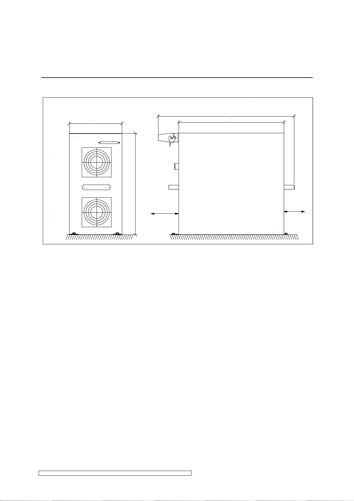
Horizontal installation position
650 mm
501 mm
Lufteintritt
air entrance
261 mm
Steckerleiste für Steuersignale
control connector
484 mm
Lufteintritt
air entrance
min. 150
Fig. 4: Assembly of the ELC 22-32kW, horizontal installation position (all dimensions in mm).
min. 150
ELC N12-N32_NE12-NE32_NE12D-NE32D-V1.0-03.17-GB Subject to technical alterations
Page 13
Installation page 11
3.2 Connection
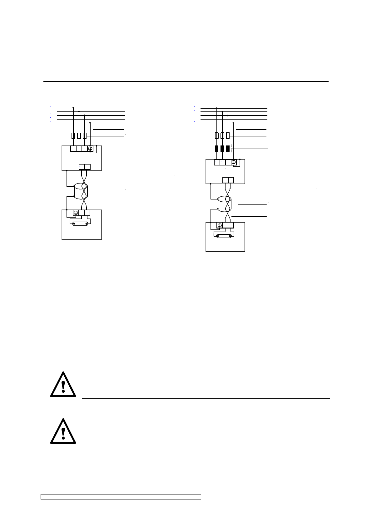
L1
L2
L3
N
PE
earthed lead network side
automatic cutout
L3
L1 L2
ELC
out2
out1
cable shield
lamp feeder cable
lamp assembly
Fig. 5: Power connection N12 - N32
L1
L2
L3
N
PE
earthed lead network side
automatic cutout
power choke
L3
L1 L2
ELC
out2
out1
cable shield
lamp feeder cable
lamp assembly
Fig. 6: Power connection NE12 – NE32
Power connection NE12D – NE32D
Fig. 5 and Fig. 6 show the respective electrical installation. Operation of appliances type
NE12-NE32 / NE12D-NE32D requires a power choke in series (see technical data chapter 6).
These appliances are implemented where the mains supply shows a low fault level or high
supply impedance.
The lamp feeder cable shielding must be connected to the ELC. To this end the connector
has an EMC screw connection (also see: connection lamp feeder cable).
If wished, the shielding can also be connected to the lamp unit.
The connection of mains supply cables and lamp feeder cables must be
separated from control cables.
For the mains power supply quality standards in accordance with EN 50160
(mains frequency, voltage drops, transients etc.) are pre-requisite.
ELCs of type “N” (N12/N16) are not designed for operation on high impedance
mains. Therefore the one-phase short-circuit power at the supply point must be
20 times higher than the nominal power of the UV installation or than the sum of
the nominal power of all electronic loads in the same arm.
ELC N12-N32_NE12-NE32_NE12D-NE32D-V1.0-03.17-GB Subject to technical alterations
Page 14
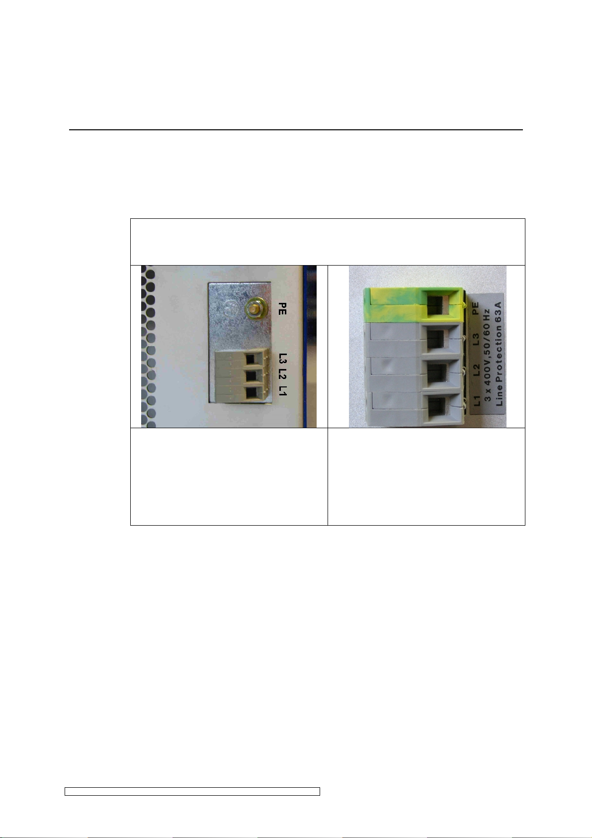
Installation page 12
Mains connection
The cross section of the earthed wire must be at least 10 mm².
The three phases must be provided with an automatic cutout.
In order to avoid damaging the terminal pins, please do not exceed the
following torque:
N12 / N16, NE12 / NE16, NE12D /
NE16D, N22 / NE22 / NE22D:
• L1, L2, L3: 1.5 – 1.8Nm
• Grounding conductor: 3.0 – 4.0Nm
N32 / NE32 / NE32D:
• L1, L2, L3: 1.5 – 1.8Nm
• Grounding conductor:1.5 – 1.8Nm
ELC N12-N32_NE12-NE32_NE12D-NE32D-V1.0-03.17-GB Subject to technical alterations
Page 15
Installation page 13
☞
7,5
100
12
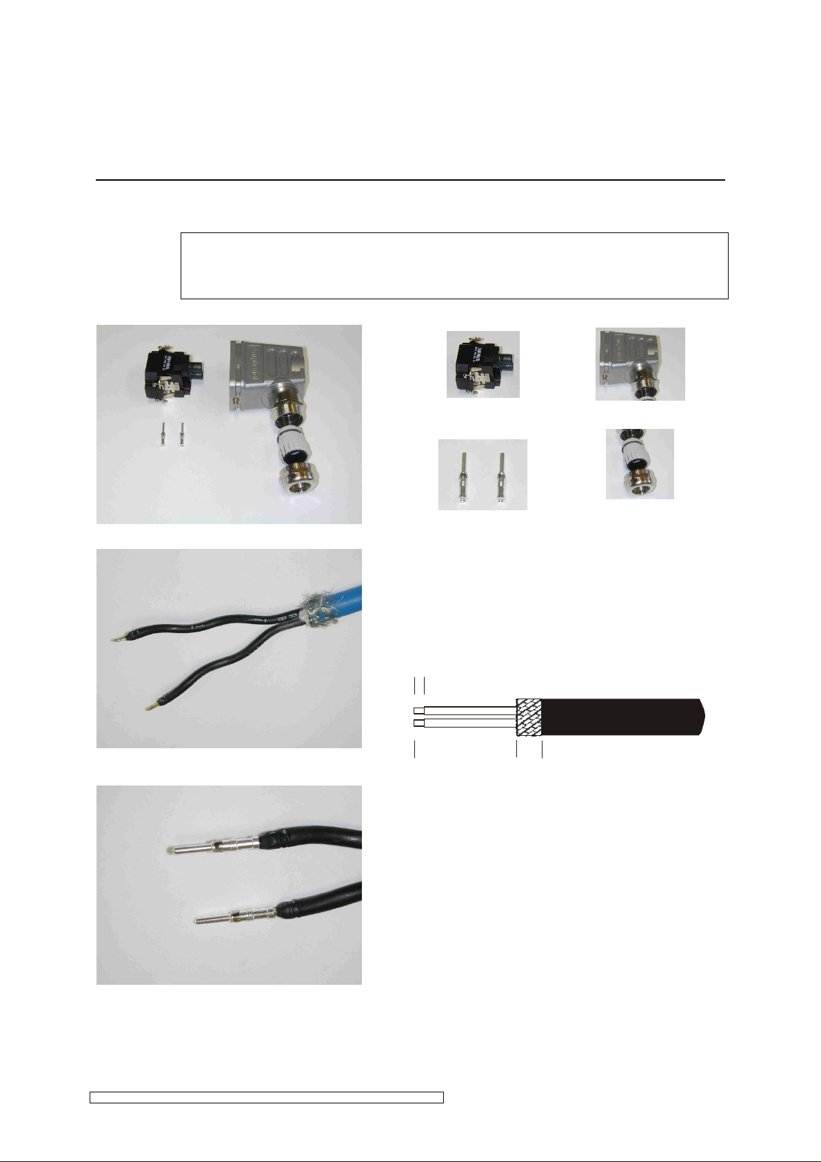
Connecting the lamp feeder cable
The lamp feeder cable must correspond with the cable parameters described in
chapter 6.
Components of the connector:
connector module
crimp contacts
Preparing the lamp feeder cable:
• Remove sheath
• Free metal braid and put over cable
sheath
• Dismantle conductor
(measurements in mm)
EMC cable gland with
hood
plastic insert
A suitable contact crimping tool is required of
the type:
Amphenol group C146
Part No.: VN01 025 0029 1C
Closed crimp barrels (individual contacts)
2.5 mm
ELC N12-N32_NE12-NE32_NE12D-NE32D-V1.0-03.17-GB Subject to technical alterations
Page 16
Installation page 14
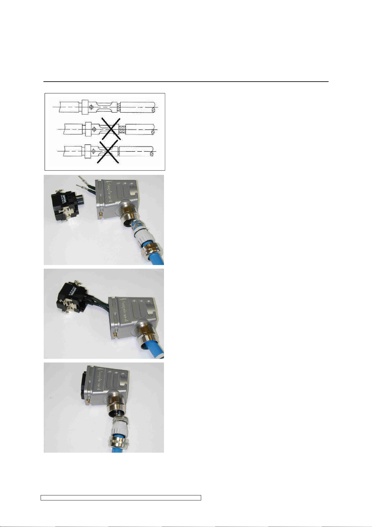
Top: Correct crimp connection
Middle: Stripped part of the wire too long, gap
between insulation and crimp barrel too large
Bottom: Stripped part of the wire too short
because conductor is not visible through
inspection hole.
• Insert cable into the cable gland and bush
casing
• Insert crimp contacts into the connector
module until they lock into place
• Ensure that the shield evenly covers the
plastic inset of the cable gland (360°
contact)
• Tighten EMC cable gland
ELC N12-N32_NE12-NE32_NE12D-NE32D-V1.0-03.17-GB Subject to technical alterations
Page 17
Installation page 15
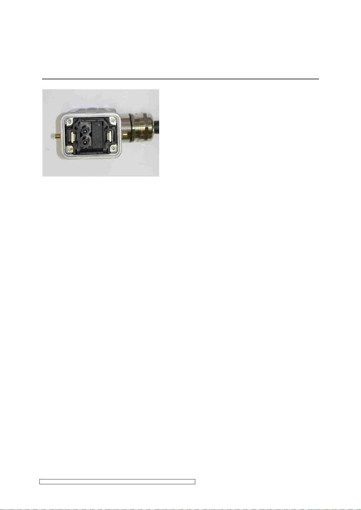
• Screw the module into the hood casing.
The picture on the left shows the
recommended orientation.
The lamp feeder cable between the switch cabinet and lamp assembly must be laid protected.
For the correct installation of the lamp assembly and lamp please observe the corresponding
manufacturer’s instructions.
ELC N12-N32_NE12-NE32_NE12D-NE32D-V1.0-03.17-GB Subject to technical alterations
Page 18
Installation page 16
3.3 Control current connections
3.3.1 Series N12 – N32 and NE12 – NE32
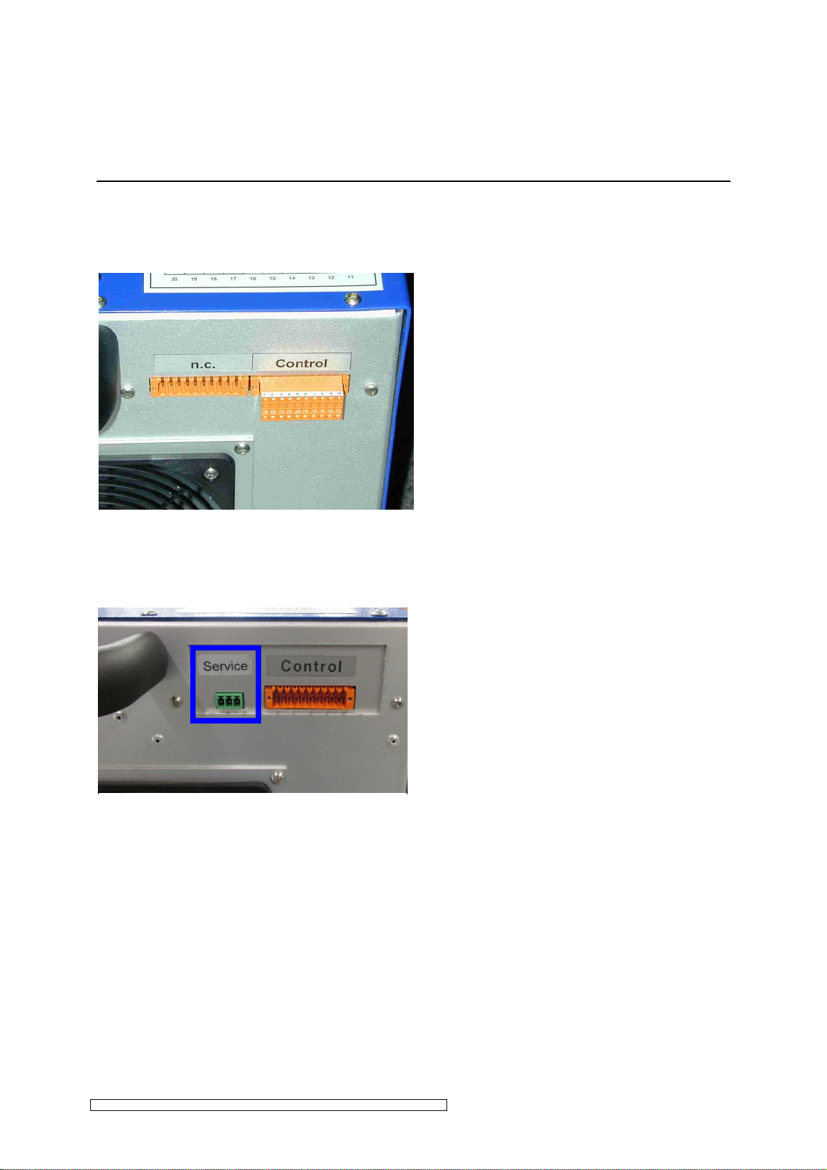
The connector for the control connection is
to be plugged into the plug strip marked
Control. (Fig. 7)
The plug strip marked "n.c.” serves no
function.
The pin assignment is shown in Fig. 9 and
Table 1.
All control circuits must be earthed upon
installation.
Fig. 7 Control current connections N, NE-Series
Fig. 7: Control current connections N, NE-Series
3.3.2 Series NE12D – NE32D
Fig. 8 Control current connections NExxD Series
Fig. 8: Control current connections NExxD-
Series
The connector for the control connection is to
be plugged into the plug strip marked Control.
(Fig. 8)
The plug strip marked with “Service” is for
internal purposes.
The pin assignment is shown in Fig. 9 and
Table 1.
All control circuits must be earthed upon
installation.
ELC N12-N32_NE12-NE32_NE12D-NE32D-V1.0-03.17-GB Subject to technical alterations
Page 19
Installation page 17
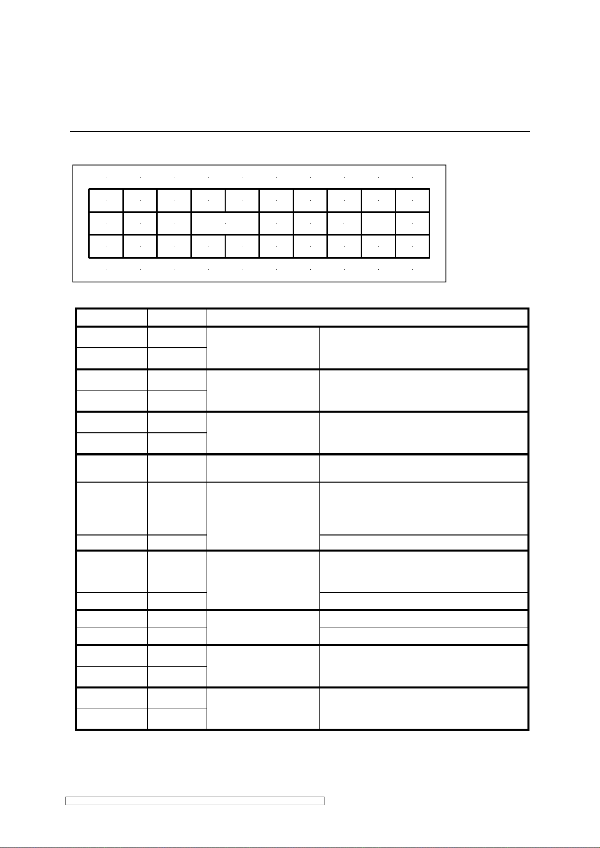
Pin assignment
1 2 3 4 5 6 7 8 9 10
Start1
ST ART SET VALU EMA X MIN
Start2
Max1 Min1 + 10 V DC 0-10V P-lamp I-lamp ES1 n.c.
Max2 Min2
GND GND
PL IL RELEAS E
GND GND ES2 OK2
E S
20 19 18 17 16 15 14 13 12 11
Fig. 9: Pin plug for control of ELC
Designation Pin No. Description
Start1 1
Start2 20
Max1 2
Max2 19
Min1 3
Min2 18
digital control input
START
digital control input
MAX
digital control input
MIN
+ 10 V DC 4 control voltage
0-10V 5
analogous control input
SET VALUE *
GND 16, 17 control GND**
15 - 30 V DC, between Pin 1 and Pin 20 input
impedance = 1 kΩ
potential-free, active high
15 - 30 V AC / DC, between Pin 2 and Pin 19
input impedance = 1 kΩ
potential-free, active high
15 - 30 V AC / DC, between Pin 3 and Pin 18
input impedance = 1 kΩ
potential-free, active high
for set value potentiometer 5 kΩ to 10 kΩ
max. 10 mA
set voltage between Pin 5 (0 –10 V) and
Pin 16,17 (GND),
input impedance > 200 kΩ (N12-N32, NE12-NE32)
input impedance > 13 kΩ (NE12D-NE32D)
OK1
n.c.
P-Lamp 6
analogous output
0-10 V DC / 1 mA, Reference: GND
1 V ≅ 1 kW appliance series up to 10 kW
1 V ≅ 4 kW appliance series above 12 kW
GND 15
PL (lamp output)
control GND**
I-Lamp 7 analogous output 0-10 V DC / 1 mA, (1 V ≅ 2 A), Reference: GND
GND 14
ES1 8
ES2 13
OK1 10
OK2 11
IL (lamp current)
Relay earth contact ES
contact, potential-free
RELEASE relay
contact, potential-free
control GND**
up to 30 V AC / DC, max. 0,5 A
Contact between Pin 8 and 13, closed in
operation, opens in the case of fault
up to 30 V AC / DC, max. 0,5 A
Contact between Pin 10 and 11, closed in
operation, opens in the case of fault
Table 1: Control current connection of ELC
* PWM coupling upon request
** control GND: all pins designated control GND are internally connected and potential-free.
ELC N12-N32_NE12-NE32_NE12D-NE32D-V1.0-03.17-GB Subject to technical alterations
Page 20
Installation page 18
3.4 Explanations of the control functions for ELC
3.4.1 Release relay
The release relay indicates the trouble-free operation of the unit.
This means that the relay closes when the ELC (see chapter 4.2) is switched on and remains
closed during operation providing there is no defect.
A typical defect would be that the lamp does not fire.
3.4.2 Control input START
High: lamp is on
Low: lamp is off
By applying the High signal the lamp is fired and warms up at maximum current until the desired
power is achieved (see below).
We recommend warm-up at maximum power. After a short time (approx. 2 mins) the full output
has been reached and the lamp power can be varied as desired.
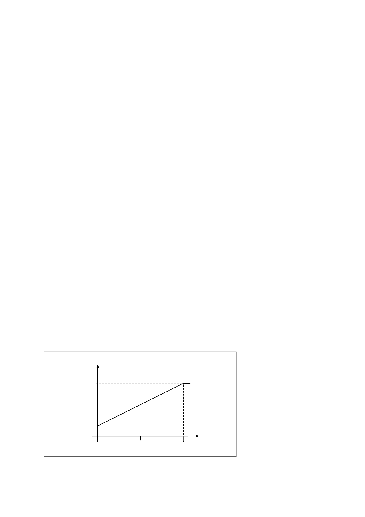
3.4.3 Setting lamp power
Stepless (infinitely variable)
The lamp can be dimmed steplessly from between approx. 20 % to 100 % of the nominal
power. The lamp power is set by applying an analog voltage of between 0 V and 10 V to control
input SET VALUE.
• 0 V corresponds to min. power P
• 10 V corresponds to max. power P
SET VALUE can be controlled manually by means of an external potentiometre.
Lampenleistung
Lamp power
100%
20 %
(20 % of nominal value)
min
(100 % of nominal value)
max
0 V
Fig. 10: Control characteristic
ELC N12-N32_NE12-NE32_NE12D-NE32D-V1.0-03.17-GB Subject to technical alterations
10 V
Set value
Page 21

Installation page 19
Digital: MIN und MAX
For certain operation modes the lamp power can be set to Maximum or Minimum independent
of the control voltage at SET VALUE. E.g.:
• Lamp warm-up: maximum power or
• Standby operation: minimum power
To this purpose the control inputs MAX and MIN respectively are set to High, whereby the
function MAX has the higher priority.
3.4.4 Table: lamp power
SET VALUE MIN MAX Lamp power
0 – 10 V LOW LOW stepless
Minimum – Maximum
0 – 10 V HIGH LOW Minimum
0 – 10 V LOW HIGH Maximum
0 – 10 V HIGH HIGH Maximum
ELC N12-N32_NE12-NE32_NE12D-NE32D-V1.0-03.17-GB Subject to technical alterations
Page 22
Installation page 20
☞
☞
3.4.5 Earth fault control
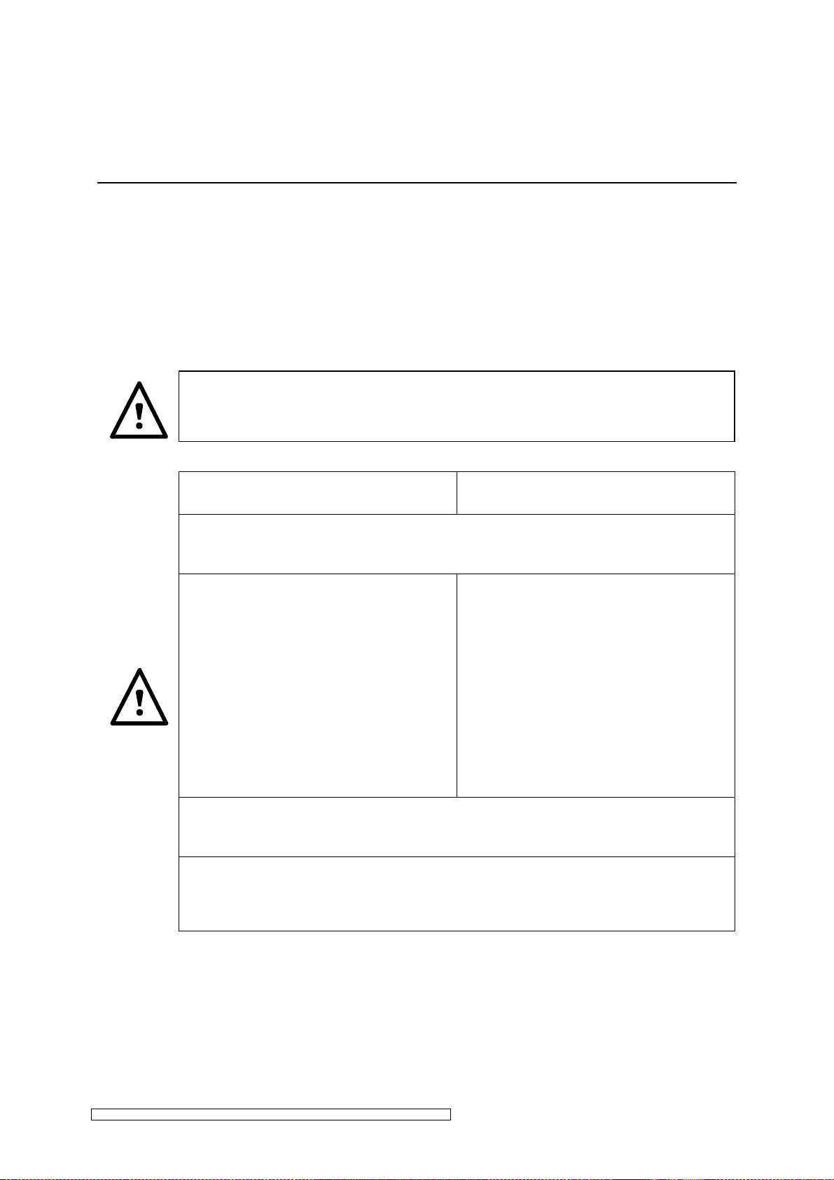
The ELC (electronic ballast) has been fitted with an earth fault control system.
The ELC is fitted with an earth fault relay ES for the purpose of indicating an earth fault. During
trouble-free operation the relay is closed (provided the ELC is connected to the power supply
voltage).
The earth fault control is also active when the lamp is switched off.
The lamp should not be switched on if the relay ES is open.
Series N12-N32 und NE12-NE32 Series NE12D-NE32D
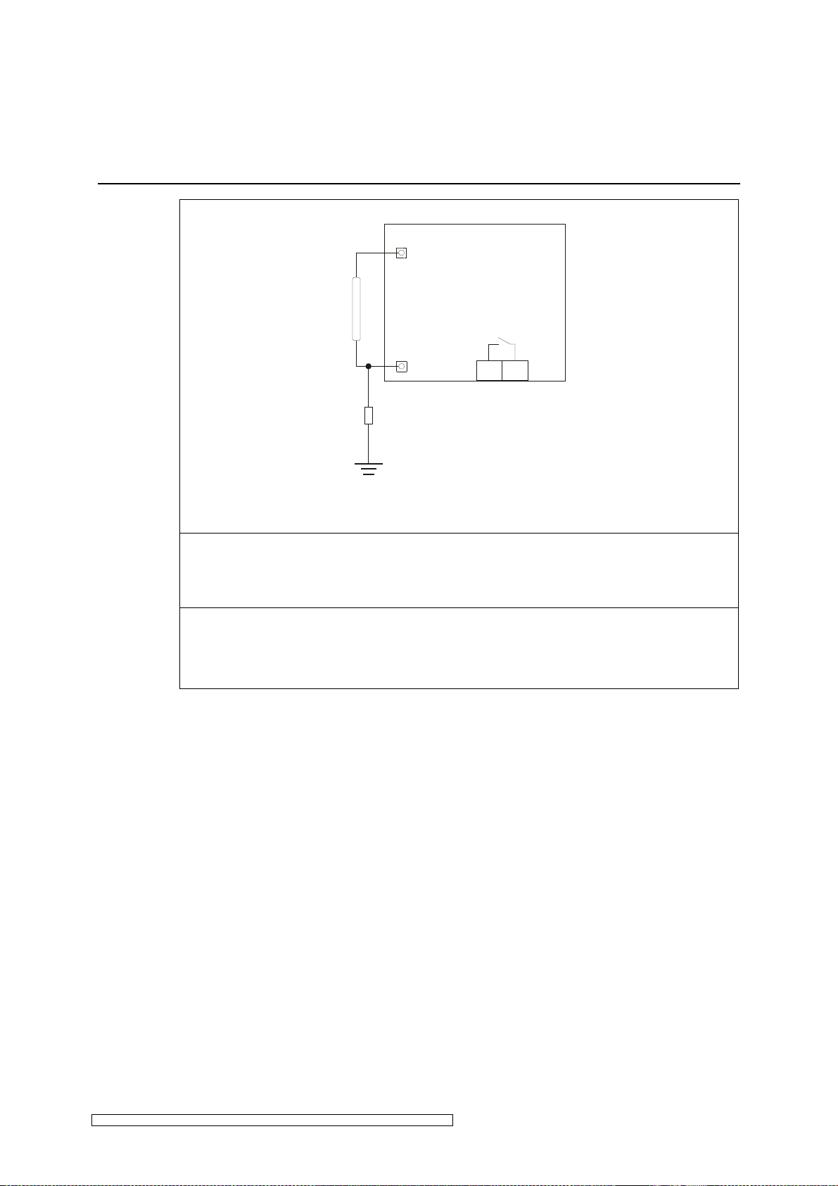
In the case of an earth fault through the isolating resistor R_error (see Fig. 11)
the relay ES opens .
The error is only displayed, the ELC
does not switch off the lamp. The error
is also not stored by the ELC.
If an earth fault occurs during lamp
operation the ballast must be switched
off immediately and the error must be
corrected. The lamp must not be
started when an earth fault has
occurred.
In order for the earth fault control to function properly it is essential that the ELC
is connected as prescribed, particularly the earth connectors.
The relay contact ES (pins 8 and 13 on the control connector) opens when the
isolation resistance R_error is below approx. 200 kΩ.
The ELC turns off the lamp. The error
is stored in the error memory of the
ELC.
If an earth fault occurs during lamp
operation, the lamp is switched off by
the ELC. In the event of an earth fault,
the lamp can not be ignited.
ELC N12-N32_NE12-NE32_NE12D-NE32D-V1.0-03.17-GB Subject to technical alterations
Page 23
Installation page 21
ES
8
13
☞
☞
Lamp
Control
R_error
Fig. 11: Earth fault monitoring
In order to avoid an unwanted reaction of the earth fault control during faultless
operation, the isolation resistance of the lamp cables and all lamp connectors
must be greater than 10 MΩ.
If the release relay RELEASE (see 3.4.1) is open the earth fault relay ES will not
give clear information! In this case an error message “earth fault“ should not be
issued.
ELC N12-N32_NE12-NE32_NE12D-NE32D-V1.0-03.17-GB Subject to technical alterations
Page 24
Operation of ELC page 22
Alterations to the manufacturer’s settings can only be carried out by the
☞
4 Operation of ELC
4.1 Initial operation
The operative parameters of the ELC, such as the scope of the trigger pulse when switching
on the lamp, is set by the manufacturer.
manufacturer. Adjustment to the internal potentiometer can cause malfunction and
damage to the equipment and is therefore prohibited.
Please assure that a suitable lamp (see chapter 6) is connected and correctly wired!
4.2 Switching on the ELC
• The ELC is switched on by applying the operating voltage.
4.3 Switching on the lamp
• A HIGH signal is applied to the digital START control input to switch on the lamp.
If a HIGH signal has already been given to the digital START control input before
the ELC is switched on, then the lamp will not start up. In the case of a power
failure, the ELC cannot automatically switch on the lamp when power returns.
Before switching on the lamp, a LOW signal must be applied to the digital control
input.
Turn the ELC on maximum lamp power during the lamp warm-up period.
Maximum lamp power can be adjusted as follows:
• HIGH signal at the digital MAX control input or
• 10 V control voltage at the analogous SET VALUE control input.
During warm-up the lamp power stays at a very low level over a longer period of time and after
approximately 60 seconds rapidly increases to its nominal power. The lamp is operated with
increased power until the nominal power is reached.
ELC N12-N32_NE12-NE32_NE12D-NE32D-V1.0-03.17-GB Subject to technical alterations
Page 25

Operation of ELC page 23
☞
control input is only
☞
4.4 Dimming Operation
After having reached nominal operation, the desired lamp power can be infinitely adjusted.
• Lamp power is adjusted via control voltage (0 – 10 V) at the analogous SET VALUE control
input.
In this context, 0 V are tantamount to minimum and 10 V to maximum lamp power.
The adjustment of lamp power via the analogous SET VALUE
possible if a LOW signal is applied to the digital MIN and MAX control inputs.
4.5 Standby Operation
During longer idle times the ELC can be switched to standby operation. The lamp is operated
at minimum power but can be brought up to nominal power within a few seconds.
Standby operation is set as follows:
• a HIGH signal at the digital MIN control input or
• 0 V control voltage at the analogous SET VALUE control input.
The warm-up time from standby operation to nominal operation depends on the lamp's ambient
conditions. If cooling is too intensive during standby operation, the acceleration time is
prolonged.
The adjustment of standby operation is only possible if a LOW signal is applied to
the digital control input MAX.
4.6 Switching off the Lamp
• The lamp is switched off by applying a LOW signal to the digital START control input.
In order to avoid heat accumulation in the ELC, the operating voltage should be
left on for a few minutes. Before restarting, the lamp must be sufficiently cooled
down as it cannot be fired otherwise.
ELC N12-N32_NE12-NE32_NE12D-NE32D-V1.0-03.17-GB Subject to technical alterations
Page 26
Troubleshooting page 24
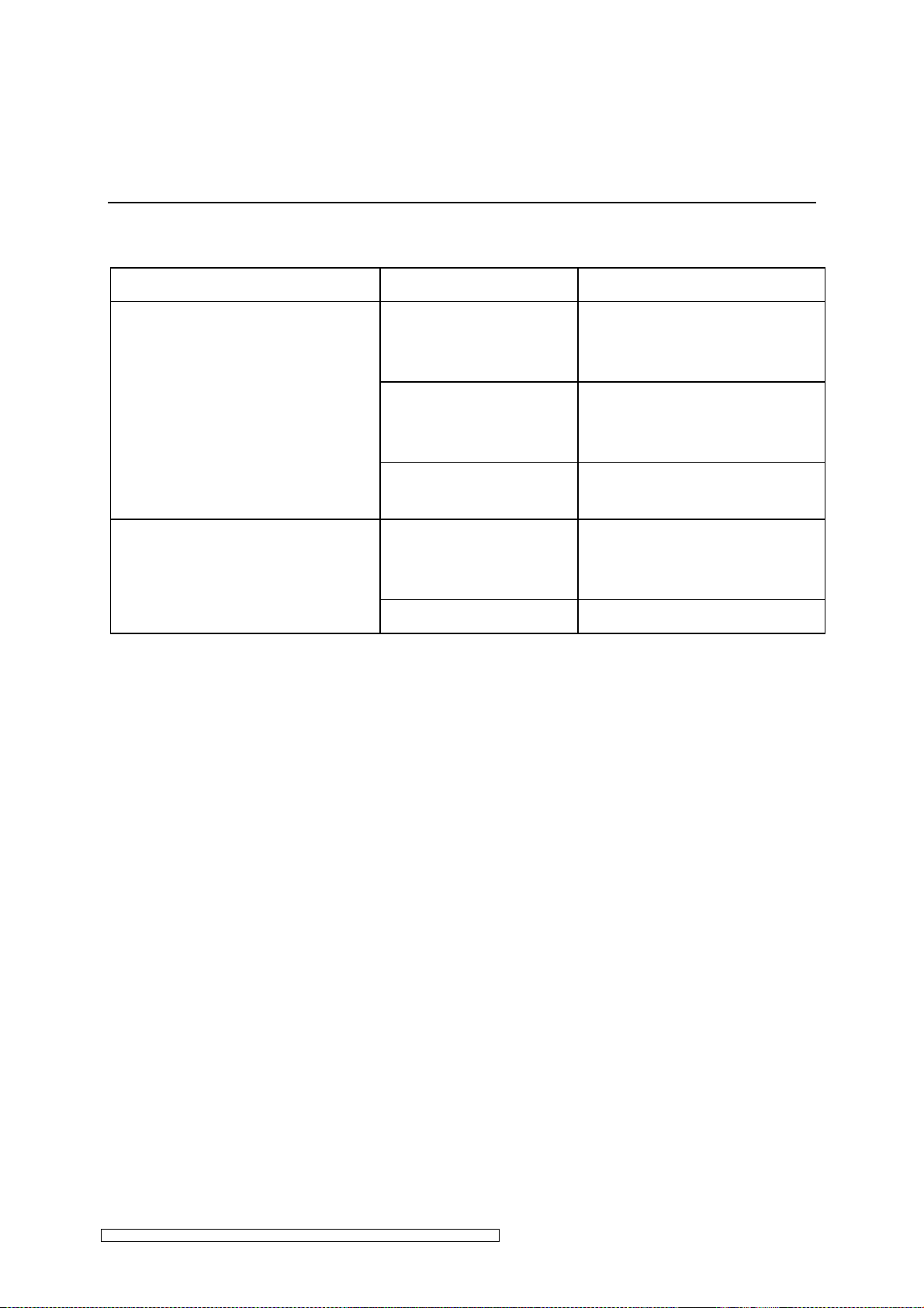
5 Troubleshooting
Troubles Possible causes Corrective action
No RELEASE after having
switched on the ELC.
Relay RELEASE open
Lamp is switched-ON
Fault in ELC Contact manufacturer,
Lamp does not fire after being
switched on, and the relay
RELEASE opens
Lamp defective Replace lamp
The ELC is not provided
with operating voltage
(control input START at
HIGH)
Lamp is too hot Let lamp cool down, increased
Check fuses and voltage of
terminals
Switch-OFF lamp
see chapter 5.1
cooling probably required
5.1 Repair of ELC
Only the manufacturer is permitted to repair the ELC. In case of failure please contact the
following address:
eta plus electronic gmbh
Lauterstraße 29
D-72622 Nürtingen
Tel: +49 7022 / 6002-80
Fax: +49 7022 / 65854
e-mail: [email protected]
ELC N12-N32_NE12-NE32_NE12D-NE32D-V1.0-03.17-GB Subject to technical alterations
Page 27

Technical Data page 25
6 Technical Data
6.1 General data ELC
Mains supply frequency
Lamp voltage tolerance
Mains voltage tolerance
Recommended air throughput
for cabinet ventilation
Control range
Protection
Permissible pollution
Permissible humidity
Installation position
EMC
Safety
Leakage current
50 / 60 Hz
Nominal voltage ± 5 %
Nominal voltage ± 10 %
160 m3 / h per ELC installed by ∆T = 10 K
approx. 20 - 100 %
IP 20
pollution severity 2 according to VDE 0110
relative atmospheric humidity 80 %, non-condensing
vertical (lamp and power connection at the top; control connections at the
bottom) or horizontal respecting the minimum spacing in 3.1.1 / 3.1.2
Verified according to
EN 55011
EN 61000-3-3
EN 61000-6-2
Verified according to
EN 50178
Leakage current > 3 mA, see chapter 1 “Safety“
ELC N12-N32_NE12-NE32_NE12D-NE32D-V1.0-03.17-GB Subject to technical alterations
Page 28
Technical Data page 26
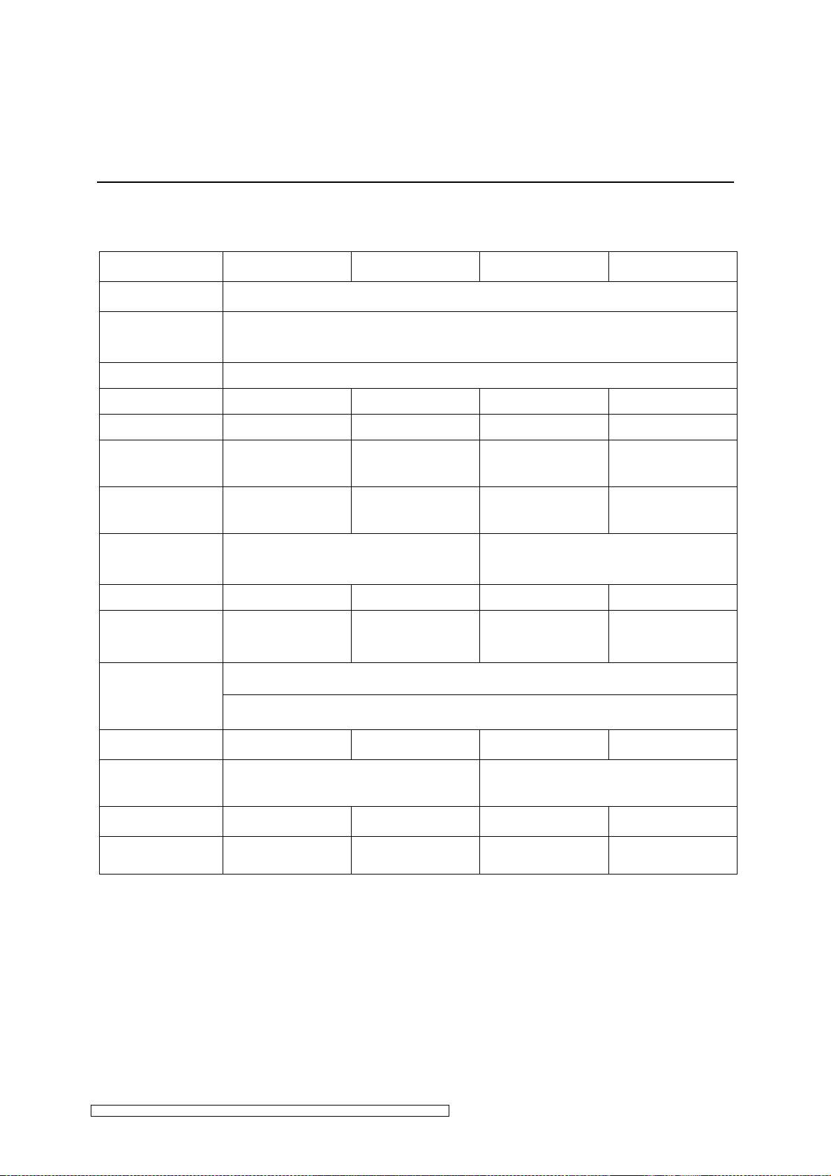
6.2 Type specific data NE12D/NE16D/NE22D/NE32D (nominal
values)
Type ELC NE12D-400-110 ELC NE16D-400-140 ELC NE22D-400-110 ELC NE12D-400-110
Power choke
Power factor
Power efficiency
Power supply
Supply current
Max. supply
current
Weight
approximately
Dimensions
(H x W x D)
Line protection*
Ambient
temperature
in operation
Ambient
temperature
during storage and
transportation
Uk = 4%
typ. 0.88
at Uk = 4% of the upstream power choke
Typ. 0.94
3 x 400 V 3 x 400 V 3 x 400 V 3 x 400 V
21,3 A 28,6 A 38,2 A 57,0 A
23,9 A 32,0 A 42,6 A 62,6 A
22 kg 22 kg ca. 29 kg ca. 37 kg
approximately 650 x 261 x 263.5 mm approximately 650 x 261 x 484 mm
25 A 32 A** / 40 A 50 A 63 A
0°C to +50°C 0°C to +45°C 0°C to +45°C 0°C to +40°C
-20°C to +70°C
before initial operation leave at least 4 hrs at room temperature
Lamp output
Ingnition voltage /
duration
Lamp voltage
Tolerance lamp
voltage
12 kW 16 kW 12 kW 16 kW
< 3000 V / < 1 sec. < 3500 V / < 1 sec.
1100 V 1400 V 1100 V 1400 V
± 6 % ± 5 % ± 6 % ± 5 %
*Line protection: 3-channel automatic cut-out characteristic C
**The use of a line protection of 32A is only possible as a mere short-circuit protection without
thermal cut-out.
ELC N12-N32_NE12-NE32_NE12D-NE32D-V1.0-03.17-GB Subject to technical alterations
Page 29
Technical Data page 27
☞
Lamp feeder cable: approved types and lengths
The use of cable types which have not been approved by the manufacturer can
lead to malfunction. The possibility of damage to the electronic ballast cannot be
excluded.
Article
no.
8067
Type ELC NE12D-400-110 NE16D-400-140 NE22D-400-110 NE32D-400-140
Lamp feeder cable 4 kV
2x2,5 mm², Ø 13,5 mm
- - 5-40 m 5-30 m
8068
The data refers to distance between and lamp.
Lamp feeder cable 1,6 kV
2x2,5 mm², Ø 10,5 mm
5-30 m 5-35 m - -
ELC N12-N32_NE12-NE32_NE12D-NE32D-V1.0-03.17-GB Subject to technical alterations
Page 30
Technical Data page 28
6.3 Type specific data NE12/NE16/NE22/NE32 (nominal values)
Typ ELC NE12-400-110 ELC NE16-400-140 ELC NE22-400-210 ELC NE32-400-280
Power choke
Power factor
Power efficiency
Power supply
Supply current
Max. supply current
bei Uk = 4% of the upstream power choke
3 x 400 V 3 x 400 V
21,3 A 28,6 A 38,2 A 57,0 A
23,9 A 32,0 A 42,6 A 62,6 A
Uk = 4%
typ. 0.88
typ. 0.94
3 x 400 V 3 x 400 V
Weight
approximately
Dimensions
(H x W x D)
Line protection*
Ambient
temperature
in operation
Ambient
temperature
during storage and
transportation
Lamp output
Ingnition voltage /
duration
Lamp voltage
Tolerance lamp
voltage
22 kg 22 kg ca. 29 kg ca. 37 kg
approximately 650 x 261 x 263.5 mm approximately 650 x 261 x 484 mm
25 A 32 A** / 40 A
0°C to +50°C 0°C to +45°C 0°C to +45°C 0°C to +40°C
-20°C to +70°C
before initial operation leave at least 4 hrs at room temperature
12 kW 16 kW
< 3000 V / < 1 sec. < 3500 V / < 1 sec.
1100 V 1400 V
± 6 % ± 5 % ± 5 % ± 5 %
*Line protection: 3-channel automatic cut-out characteristic C
50 A 63 A
22 kW 32 kW
2100 V 2800 V
**The use of a line protection of 32A is only possible as a mere short-circuit protection without
thermal cut-out.
ELC N12-N32_NE12-NE32_NE12D-NE32D-V1.0-03.17-GB Subject to technical alterations
Page 31
Technical Data page 29
☞
Lamp feeder cable: approved types and lengths
The use of cable types which have not been approved by the manufacturer can
lead to malfunction. The possibility of damage to the electronic ballast cannot be
excluded.
Article
no.
8067
8068
The data refers to distance between and lamp.
Type ELC NE12-400-110 NE16-400-140 NE22-400-110 NE32-400-140
Lamp feeder cable 4 kV
2x2,5 mm², Ø 13,5 mm
Lamp feeder cable 1,6 kV
2x2,5 mm², Ø 10,5 mm
- - 5-40 m 5-30 m
5-30 m 5-35 m - -
ELC N12-N32_NE12-NE32_NE12D-NE32D-V1.0-03.17-GB Subject to technical alterations
Page 32

Technical Data page 30
6.4 Type specific data N12/N16/N22/N32 (nominal values)
Typ ELC NE12-400-110 ELC NE16-400-140 ELC NE22-400-210 ELC NE32-400-280
Power choke
Power factor
Power efficiency
Power supply
Supply current
Max. supply current
Weight
approximately
Dimensions
(H x W x D)
Line protection*
Ambient
temperature
in operation
Ambient
temperature
during storage and
transportation
-
typ. 0.93
typ. 0.96
3 x 400 V 3 x 400 V 3 x 400 V 3 x 400 V
19,8 A 19,8 A 19,8 A 19,8 A
21,7 A 21,7 A 21,7 A 21,7 A
21 kg 21 kg 21 kg 21 kg
approximately 650 x 261 x 263.5 mm approximately 650 x 261 x 484 mm
25 A 25 A 25 A 25 A
0°C to +50°C 0°C to +50°C 0°C to +50°C 0°C to +50°C
-20°C to +70°C
before initial operation leave at least 4 hrs at room temperature
Lamp output
Ingnition voltage /
duration
Lamp voltage
Tolerance lamp
voltage
12 kW 12 kW 12 kW 12 kW
< 3000 V / < 1 sec. < 3500 V / < 1 sec.
1100 V 1100 V 1100 V 1100 V
± 6 % ± 6 % ± 6 % ± 6 %
*Line protection: 3-channel automatic cut-out characteristic C
**The use of a line protection of 32A is only possible as a mere short-circuit protection without
thermal cut-out.
ELC N12-N32_NE12-NE32_NE12D-NE32D-V1.0-03.17-GB Subject to technical alterations
Page 33
Technical Data page 31
☞
Lamp feeder cable: approved types and lengths
The use of cable types which have not been approved by the manufacturer can
lead to malfunction. The possibility of damage to the electronic ballast cannot be
excluded.
Article
no.
8067
Type ELC N12-400-110 N16-400-140 N22-400-110 N32-400-140
Lamp feeder cable 4 kV
2x2,5 mm², Ø 13,5 mm
- - 5-40 m 5-30 m
8068
The data refers to distance between and lamp.
Lamp feeder cable 1,6 kV
2x2,5 mm², Ø 10,5 mm
5-30 m 5-35 m - -
ELC N12-N32_NE12-NE32_NE12D-NE32D-V1.0-03.17-GB Subject to technical alterations
 Loading...