

Page 1

Transit lll
Manual English
74173H 2015- 01-21
Page 2

Contents
Heading Page
1. General .................................................................................................................... 3
2. Handling/Transport ................................................................................................. 4-5
3. Product Description Transit ................................................................................... 6
4. Model Transit ........................................................................................................... 7
5. Options/Accessories ................................................................................................. 8-10
6. Settings Seat ............................................................................................ 11-12
7 Brake ......................................................................................... 12
8. Backrest....................................................................................... 13
9. Legrests ..................................................................................... 14-15
10. Armrests .................................................................................... 16
11. Driving technique/Manoeuvring................................................................................ 17-19
12. Assembly instructions Accessories ............................................................................ 20-21
13. Care and Maintenance/Fault-finding chart .............................................................. 22-23
14 Tests and Guarantees ................................................................................................. 24
15. Weights and Measurements/Standard models ........................................................... 25
.
2
Page 3

1 General
The manual must be read thoroughly to avoid damage when handling and using the Transit chair.
is a warning triangle to indicate that special care should be taken.
(!) provides advice and tips worth considering
Transit is a manual cross-folded transportation wheelchair with variation options that is primarily intended for outdoor
use. The angle of the seat is adjustable. Backrest and footrests are adjustable in height and angle. In addition there is a
range of options and accessories: Various types of legrests, seat cushions, height-adjustable push handles, anti-tips etc.
Transit is easy to handle and has excellent seating comfort, functionality and manoeuvrability.
Crash test
Etac’s wheelchairs are tested in accordance with ISO 7176-19 and 10542. These ISO standards specify requirements
for the design of the wheelchair’s restraint points, how the wheelchair and the user are secured in the vehicle and
describe how testing should be carried out and how the test results are to be interpreted. Etac’s wheelchairs are crash
tested at the Technical Research Institute of Sweden. The test was carried out with normal settings on the wheelchairs
(see manual for the respective chair) and with an UNWIN_WWR/ATF/K/R restraining device and an
UNWIN_WWR/HD/ATF/K/R 3-point belt.
The cross-folded wheelchairs Cross, Twin and Transit were supplemented with securing points.
Seat widths: 35, 40, 45, 50 and 55 cm
Seat depth: 42 cm
Max. user weight: 135 kg
Seat height front: 51 cm
Seat height back: 49 cm
Backrest height: Standard 40 cm. Adjustable to 42.5, 45 or 47,5 cm.
Rear wheel: 16” x 2” pneumatic rear wheel, fixed axle
Transit is supplied with a lockable legrest by which the chair can be carried.
The height of the armrest is 26 cm from the seat.
Service life: The product is tested and fulfils the demands stated in EN 12183. The main product’s durability and lifetime is at least five years when used in accordance with intended use, the safety instructions, the reconditioning manual
and instructions for use in the user manual. The main product consists of the chassis for seat and back support. Additional parts/accessories are handled in accordance with the manual and reconditioning manual. The actual lifetime can
vary, depending on how much and how intensively the product is being used, but a maximum of 10 years. Thereafter
the product must be decommissioned.
The following methods of surface treatment have been used:
Lacquered surfaces=Polyester powder coating
Non-lacquered aluminium parts=Anodized coating
Non-lacquered steel surfaces=Galvanized
The tool kit contains: 5 Allen keys: d6, 5, 5, 4 and 3 mm
3 Ring spanners: 13, 10 and 8 mm
1 Socket spanner: 24/19 mm
1 Phillips screwdriver
3
Page 4

2 Handling and Transportation
2:1 Folding
- Flip up the footrests
- Lift up the seat, see illustration
2:2 Unfolding
- Press down on one side of the
seat frame using the whole of
the hand, see illustration
2:3 Lifting the wheelchair
Wheelchair with lockable legrests:
- Lift using the push handles and
the legrests.
- If the chair is equipped with
height-adjustable push handles,
ensure that the knobs are
properly tightened.
Do not hold the seat frame
tube while unfolding as there
is a risk of fingers being
crushed
This is especially important if the
chair is to be lifted with the user
sitting in it. Etac also recommends
fixed push handles for everyday use on
stairs.
2:4 Transportation in vehicles
Private car/taxi: The wheelchair
should be placed in the car boot. If
this is not possible, ensure that the
wheelchair is placed safely in the back
seat, so that it is not able to overturn
or roll.
If possible secure the wheelchair with
the car’s safety belt.
4
Page 5

2 Handling/Transportation
300mm
25°
25°
300mm
2:5 Securing
The wheelchair must be secured as
follows, the straps must not be put
through the wheels or around the back
tubes.
2:6 Seat belt
If the wheelchair is used as a seat for
travel, Etac recommends that the user
uses the 3-point belt that is fitted in
the vehicle.
2:7 Recommendations
Etac recommends in the following
order:
1) The user transfers to a seat in the
vehicle and uses the vehicle’s 3-point
belt while travelling. The wheelchair
is then placed in the boot or safely
in the back seat so that it cannot
overturn or roll.
2) The wheelchair is secured facing
forwards in the vehicle as per this
manual, the user uses a separate
3-point belt that is secured in the
vehicle. This is the way in which the
wheelchair is tested and approved
It is important that the 3-point belt is
fitted correctly, as in the illustrations:
according to the ISO-standard for
crash testing of wheelchairs in vehicles.
3) According to directive 2001/85/
EC, appendix VII, point 3.8.3. there
are specially marked wheelchair
locations in vehicles that permit
transport with a wheelchair facing in
the direction of travel. If this means
of travel is used, the user/carer must
be aware while travelling, prepared
for sudden movements and have the
capacity to maintain a safe sitting
position throughout the entire journey.
The user’s disabilities must not be of
such an extent that he/she is not able
to hold onto the handles fitted in the
vehicle when there are changes of
speed or direction.
In conjunction with points 2 and 3:
- a 25668 positioning belt shall
be used
- a correctly adjusted headrest shall
be used
- the backrest shall be level with or
above the user’s shoulders
- the parking brake shall be used
- the anti-tips shall be lowered
- backrest brace shall be used
2:8 Warning
- The wheelchair’s positioning
belt is not sufficient to prevent
the user from being thrown out
of the wheelchair in the event of
sudden braking.
- The restraining device must not
- Options/accessories that can be
removed without tools, such as
trays, shall be removed and
secured/positioned so that they
do not fly around inside the
vehicle in the event of a collision.
- If the wheelchair has been
involved in a collision in a motor
vehicle, it should be inspected at
a Technical Aids Centre or by
Etac before being used again.
be put through the wheels or
around the back tubes.
5
Page 6

3 Product description Transit III
3
4
17
18
1
2
5
6
7
8
9
10
12
14
15
11
16
13
1 Brake handle drum brake/parking brake 10 Attachment tube footrest
2 Brake cable 11 Footrest:
3 Back tube 12 Knob footrest lock
4 Backrest upholstery 13 8” Allround castor
5 Armrest short 14 Front fork
6 Mudguard 15 Cross
7 Seat upholstery 16 Side frame
8 Locking mechanism lockable legrest 17 16” pneumatic rear wheel
9 Angled legrest 18 Armrest attachment
6
Page 7

4 Model Transit III
Standard model
Seat height
Front seat height set at 51 cm
Rear seat height set at 49 cm
Front fork with steel axle
8” x 2” castor wheel
7” x 2” castor wheel
solid or pneumatic options are available
Seat upholstery fixed
16” x 2” or 12” x 2” rear wheel with drum brake/parking brake
Pneumatic or solid
Fixed axle
Camber angle 0°
Backrest adjustable in height, angle and shape
Backrest height adjustable to 40, 42.5, 45 and 47,5 cm.
Backrest angle adjustable between -6°-+6° in fixed positions. Assembled at 0°
Backrest upholstery fixed
Fixed push handles or rear-positioned height adjustable
Legrests removable, can be swung to the side/lockable
Legrests wide/lockable, black
Footrests flip-up, foldable, adjustable in height and angle.
Tilter integrated in the frame.
Armrest height-adjustable 25 cm long, solid flat, black
7
Page 8

5 Options/Accessories
Backrest upholstery adjustable
Armrest height-adjustable 38 cm long, solid flat, black
Armrest cover detachable, 25 or 38 cm long
padded or gel, dark grey plush or black Dartex
Armrest cushion wide and soft, 8x40 cm, fits onto armrest
Widening kit to extend the armrests 10 mm on each side
Tray transparent, fits onto long armrest
Hemi tray, width up to 50 cm, Can be supplemented with an anti-slip device
Hard seat height 2 cm lower than cloth upholstery. Easy to take off when folding.
Seat cushion dark grey plush and black velour, 56 cm, cut according to seat depth set, washable
Positioning belt two pieces, with fixing points on the wheelchair frame
Legrest lockable, narrow angle or short with narrow angle
Angle adjustable legrest model 1 with calf support adjustable in height, depth, angle and sideways
Amputee legrest settable in height, length, angle and sideways.
Can be combined with amputee weights.
Settable= Adjusted using tools.
Adjustable= Adjusted without tools
8
Page 9

5 Options/Accessories
Footrests with short attachment tube to be combined with short narrow legrest
Heel straps black nylon, adjustable length
Extended footrest fits onto the existing footrest, from seat width 40-55 cm
One-piece footrest foldable, adjustable in height and angle
Calf strap detachable, black nylon, adjustable in length
Padding for calf strap
Push handles vertically adjustable, detachable
User brake
Anti-tips can be folded up, fixed length
Anti-tips telescopic, foldable, adjustable height, length and angle
Cane holder two parts, one of which is an elasticated section which is fastened around the cane.
Transport attachment
Tool kit
Bags
9
Page 10
5 Options/Accessories
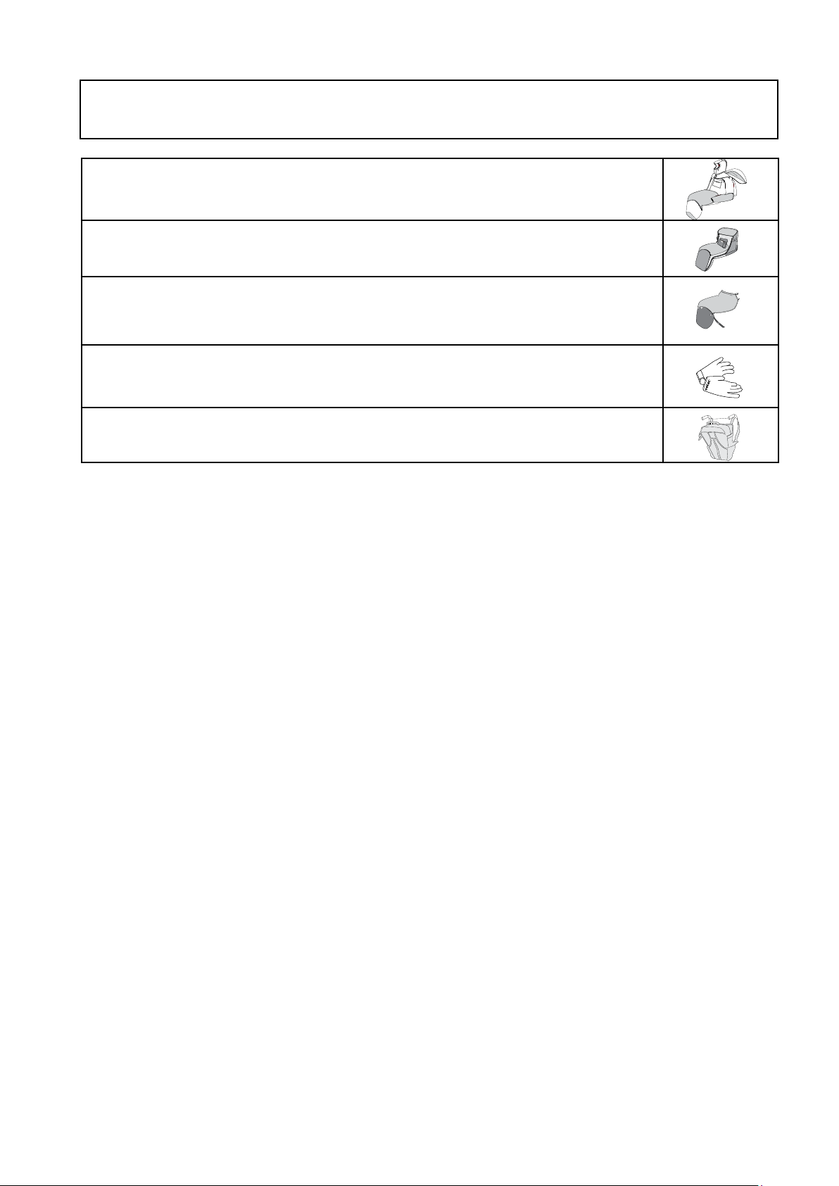
Rain cape Proof Information is available at www.etacbutiken.se
Weather protector Proof Information is available at www.etacbutiken.se
Leg warmer Proof Information is available at www.etacbutiken.se
Gloves Information is available at www.etacbutiken.se
Bags Case Logic Information is available at www.etacbutiken.se
10
Page 11
6 Settings seat
6:1 Front seat height
The front seat height is 51 cm.
The rear seat height is 49 cm.
Front wheel 8” allround
Front fork with steel axle
Rear wheel 16” pneumatic
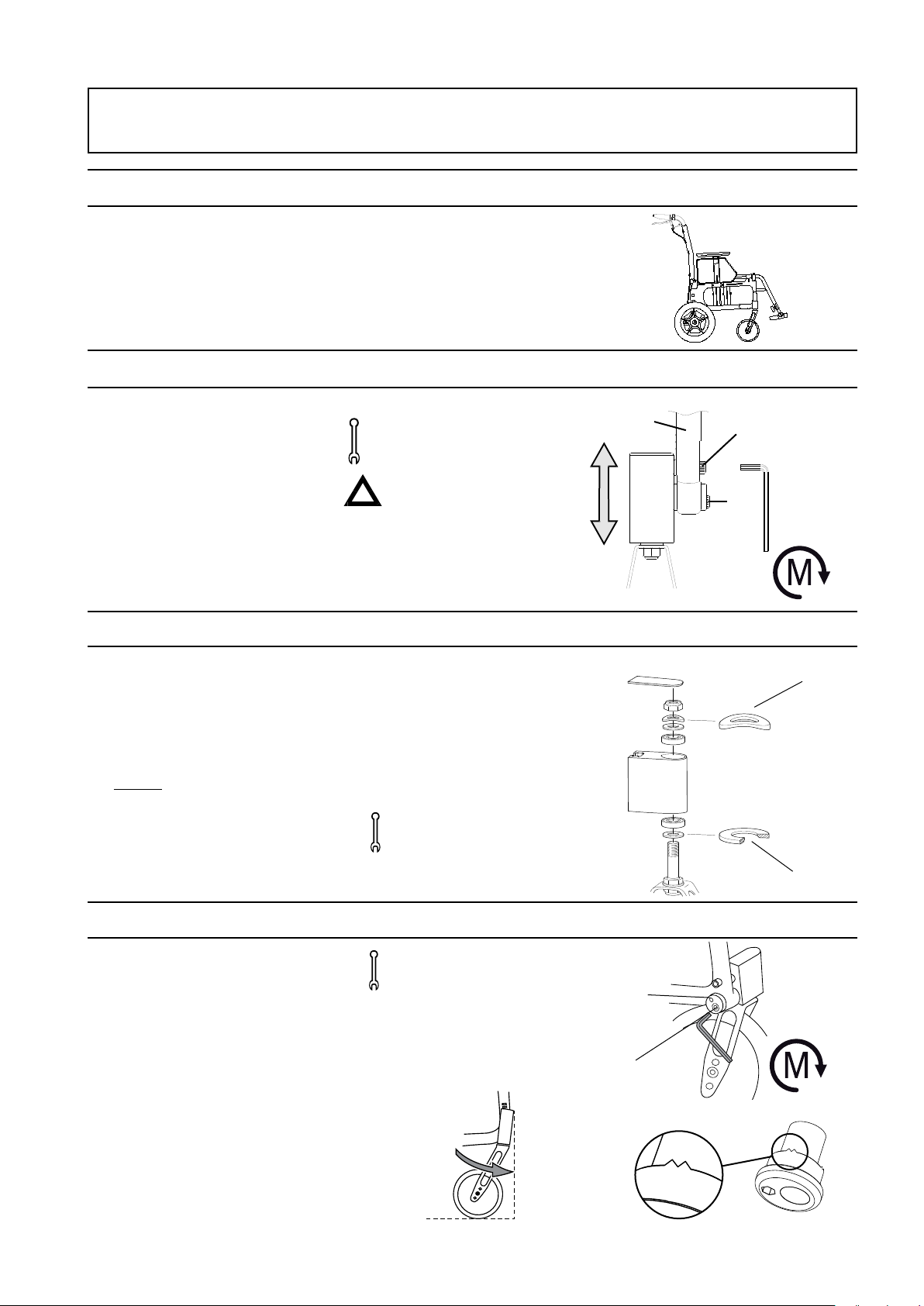
6:2 Adjusting the height of the front fork attachment
The height of the front fork can
be adjusted 4 cm up or down by
loosening the two attachment screws
(A and B) 1-2 turns. See position
marking (C) to obtain equal height on
both sides.
Check and adjust the angle of the
attachment and tighten the screws.
6:3 Changing front fork
Unscrew the protective stopper on
the front fork attachment to reach
the retaining nut. Unscrew the nut
and pull out the front fork. Take the
washer and ball bearings and put it
on the new fork (the bevelled side
(A) towards the fork). It is important
to ensure that the washers in the
attachment (under the retaining nut)
are placed in the right order, with the
spring washer (B) on top.
Tools: 6 mm Allen key
(a spirit level might be
useful).
Risk of tipping: Always
check the setting of the the
anti-tips.
(!) Also adjust the angle of the
front fork attachment, see
point 6:4.
Tighten the retaining nut until it
cannot be turned any more. Then
loosen it
½-1 turn. The spring washer then has
the correct tension. It reduces the risk
of the castor starting to ”wobble”.
Tools: 19 mm box spanner
and Phillips screwdriver
C
A
B
20Nm
B
A
6:4 Setting the angle of the front fork attachment
The correct angle setting is important
for the wheelchair’s manoeuvrability.
- Loosen the lower attachment
screw (A) about 2 turns so that
the tag (C) moves freely inside
the shaft. Insert the Allen key in
the hole (B) and turn until the
attachment is perpendicular to
the floor. Always start from a
position that enables the wheel
to move forward in the rotation
(D). Hold the shaft in place while
the lower attachment screw is
tightened.
Tools: 6 mm Allen key
(a spirit level if necessary)
(!) Keep your eye on
something vertical,
e.g. a door frame or table leg
while setting the angle.
D
B
A
20Nm
C
11
Page 12

6:5 Seat depth, adjustable seat upholstery
6 Settings seat
The seat depth can be adjusted 0-6 cm
by lifting the front
seat upholstery and sliding it
backwards or forwards.
36 - 42 cm (measured from backrest).
7:1 Drum brake
To operate the drum brake pull brake
handle upwards (see picture).
(!) Adjustable backrest upholstery.
Functional seat depth
42-48 cm is dependent on
the backrest upholstery’s
adjustment, see point 8:4.
7 Brake settings
36-42 cm
7:2 Parking brake
To operate the parking brake pull
brake handle upwards (see picture).
Hold the handle in braked position
7:3 Adjusting the brakes
When adjusting the brake loosen nut
(A) and adjust the brake by moving
(B) up/down. When the brake has a
reasonable effect tighten nut (A). This
adjustment is recommended when the
brake is not functioning satisfactorily.
and press button (A) down. The chair
is now braked. Pull the handle upwards to release the parking brake.
A
Tools: 8 mm spanner
B
A
12
Page 13

-6
8:1 Backrest angle
8 Backrest settings
The angle can be set in the fixed
Tools: 10 mm ring spanner
positions -6°, -3°, 0°, +3° and +6°.
Loosen nut (A), remove the screw and
set at required angle, retighten the nut.
8:2 Backrest height
The backrest is adjustable to a height
of 40, 42.5, 45 and 47,5 cm. Undo
Tools: 3 mm Allen key,
8 mm ring spanner.
the screws (A). Pull the backrest
upholstery upwards. Unscrew the nuts
(B) and adjust to the desired height.
Make sure that both sides have the
same height.
8:3 Backrest height for vertically adjustable push handles (option)
+6°
-6°
A
0
6
-3
3
A
B
The backrest is adjustable to a height
of 40, 42.5 and 45 cm.
Undo the screws (A). Remove the
push handle attachment.
Unscrew the screws (B) and adjust
to the desired height. Make sure that
both sides have the same height.
8:4 Backrest upholstery (option)
The form of the backrest upholstery is
individually adjustable by means of five
Velcro straps and the backrest cover.
- Give the backrest cover ample
space between the seat and
backrest, allowing the user to ”sit
in” against the backrest.
- Loosen all straps and ensure that
the user is sitting as far back in
the seat as possible.
- Tighten the straps in such a way
that they follow the contours of
Tools: 3 mm, 5 mm
Allen key, 8 mm
ring spanner
A
B
the user’s back and give plenty of
support to the lumbar region.
Risk of tipping: Always
check the position of the
anti-tips when adjusting
the backrest upholstery.
(!) Do not overtighten the upper
straps as this can prevent
the cross-brace from unfolding
properly, i.e. the seat-frame tubes
do not sit flush in the sideframes.
13
Page 14

9:1 Lockable legrests
Transit is supplied with lockable
legrests as standard. They are removable and can be swung to the side or
under the seat. To remove the legrests
press down on the red button (A) and
lift. To fasten the legrests press down
on the red button (B) as shown in the
illustration, put the legrest into place
and release the button. The legrest is
now locked, see picture (A).
9:2 Height of the footrests
9 Settings footrests
Never stand on the footrests
as the chair may tip!
AB
Transit is supplied with divided,
flip-up footrests that are adjustable in
height, angle and depth.
Height Loosen the locking handle (A)
on the legrest fully. Set the height.
Replace the screw and handle. Tighten
securely. Max. length: 51 cm. Min.
length: 33 cm.
9:3 Angle and depth of the footrests
The footrests can also be adjusted in
angle and depth.
Angle Loosen the screws (A) slightly.
Adjust to the required position and
tighten again.
Tools: 5 mm Allen key.
(!) -To make the footrests
higher than standard there
are also short/narrow legrests
with footrests with 8 cm
shorter attachment tubes.
- To make the footrests lower
than standard there are
footrests with 10 cm longer
attachment tubes.
For outdoor use the footrests
should be 4-5 cm above
ground level. Never stand on
the footrests as the chair may
tip!
Depth The sides of the footrests
have different lengths. By changing
the left side for the right they will
extend further forwards.
(!) If the depth is altered,
the angle must also be adjusted.
A
A
14
Page 15

9 Settings footrests
9:4 Continuously angle-adjustable legrest (option)
With or without plush covered
calf support which is adjustable in
height, depth and angle. The calf
support can also be mounted as
a knee support.
(!) See supplied assembly
instructions for
mounting the calf support.
Never stand on the
footrests as the chair may
tip! When lifting a
wheelchair, remove the
legrests and lift using the
frame (lower or upper
tubes).
15
Page 16

10:1 Armrests, height adjustment
10 Settings armrests
The lock lug is used both to set the
height of the armrest and secure the
side guard:
- Loosen the screw that fastens
the lock lug.
- Slide the side guard up or down
to the desired height.
- Refasten the lug on
the side guard.
Tools: 3 mm Allen key.
Never use the armrests to
lift the wheelchair.
The detachable armrest comes in two
versions, with short or long armrest
guard. The armrest attachment can
be fitted in 2 different heights. In
position 1 the height of the armrest is
adjustable between 19 and 26 cm, and
in position 2 (standard) between 24
and 31 cm, with 1 cm intervals.
If necessary the right armrest can be
fitted on the left side and vice-versa.
Tools: 5 mm Allen key.
1
2
16
Page 17

11 Driving technique, manoeuvring
11:1 General
Parking: Increase the overall support
base of the wheelchair by reversing
for about 10 cm, thereby ensuring the
castor wheels swing forwards.
If the user is left alone in the
wheelchair, ensure that the brakes are
applied and that the anti-tip is swung
down.
11:2 Driving technique, kerbs and raised thresholds: up
If the chair is equipped with
height-adjustable push
handles, ensure that the
knobs are properly tightened.
This is especially important if
the chair is to be lifted with
the user sitting in it. Etac also
recommends fixed push
handles for everyday use on
stairs.
Care giver, driving up forwards:
- If anti-tips are used, turn
them upwards.
- Tilt the wheelchair, with help
from the tilter, so that the
castor wheels come up onto
the pavement.
- Lift by the push handles to
help the rear wheels up.
Care giver, driving up backwards:
- Reverse the wheelchair up to
the kerb/threshold.
11:3 Driving technique, kerb: down
Care giver, driving down forwards:
- If anti-tips are used, fold
them upwards.
- Tilt the wheelchair, if necessary
with the help of the tilter, so
that the castor wheels are in the
air.
- Drive carefully down the kerb,
and set down the castor wheels
on the ground.
- Tilt the wheelchair, if necessary
with the help of the tilter, so
that the castor wheels are in the
air.
- Pull the wheelchair up and
backwards ensuring that the
castor wheels are over the edge
before setting down the
wheelchair on all 4 wheels.
- If anti-tips are used, fold
them downwards.
- Reverse carefully down the
kerb, and continue backwards
on the rear wheels until the
castor wheels have cleared the
obstacle.
- Set down the wheelchair once
again on all four wheels.
- If anti-tips are used, fold
them downwards.
Care giver, driving down backwards:
- Reverse the wheelchair up to
the edge of the kerb.
17
Page 18

11 Driving technique, manoeuvring
11:4 Driving technique, stairs: Up
We always recommend using
two carers for this transfer.
One who walks behind and
holds on to the push handle
and one who walks in front
and holds on to the frame (or
in the legrests if these are
lockable).
With care giver, backwards:
- If anti-tips are used, fold
them upwards.
- Reverse the wheelchair to the
first step.
- Tilt the chair onto the rear
wheels, using the tilter.
- Pull the wheelchair slowly
upwards, one step at a time,
keeping it balanced on
the rear wheels at all times.
- When the last step has been
cleared, continue backwards
so that the castor wheels are
over the ground before
setting down the wheelchair
on all four wheels.
- If anti-tips are used, fold them
downwards.
(!) While lifting the care givers
should remember to use the
power of their legs and keep
their backs as straight as
possible
11:5 Driving technique, stairs: down
We always recommend using
two carers for this transfer.
One who walks behind and
holds on to the push handle
and one who walks in front
and holds on to the frame (or
in the legrests if these are
lockable).
With care giver, forwards:
- If anti-tips are used, fold
them upwards.
- Drive forwards to the first step
and tilt the wheelchair back
onto the rear wheels, using
the tilter.
- Descend carefully one step
at a time, keeping the
wheelchair balanced on
its rear wheels at all times.
- After the last step, set
down the wheelchair on all four
wheels.
- If anti-tips are used, fold
them downwards.
(!) While lifting the care givers
should remember to use the
power of their legs and keep
their backs as straight as
possible.
18
Page 19

11 Driving technique, manoeuvring
11:6 Manoeuvring, transferring into/out of the wheelchair
The technique for transferring a
user should be practised with trained
personnel. All that is provided here is
some important advice to consider in
conjunction with transferring a user
into or out of the wheelchair.
With or without a care giver, sideways.
Before transferring:
- Increase the overall support
base of the wheelchair by
reversing for about 10 cm,
thereby ensuring the castor
wheels swing forwards.
The wheelchair should be
positioned as close to the place
where the transfer is going to
take place as possible.
- Lock the brakes, remove or
swing up armrest/sideguard
and legrest on the side where
the transfer is to take place.
With or without a care giver, from the
front.
Before transferring:
- Increase the overall support
base of the wheelchair by
reversing for about 10 cm,
thereby ensuring the castor
wheels swing forwards.
The wheelchair should be
positioned close to where
the transfer is to take place.
- Apply the brakes, remove the
armrest/side guard and swing
the legrest in under the seat
one the side you intend to
move across.
Never stand on the footrests
as you may tip the chair!
(!) While lifting the care givers
should remember to use the
power of their legs and keep
their backs as straight as
possible.
19
Page 20

12 Assembly instructions accessories
12:1 Padded cover, armrest
The detachable armrest can either be
supplemented with, or ordered complete with, a padded or gel cover.
They are manufactured in dark grey
plush, or alternatively black Dartex,
and they are washable.
12:2 Tray
The tray is transparente, with a recess
to fit round the body. It is mounted
on long armrests using Velcro straps.
The height is adjusted along with the
armrests.
12:3 Positioning belt
The positioning belt is in two parts, is
adjustable in length and has a snaplock. It can be mounted either on the
backrest joint (A) or in the holes just
in front of the backrest joint (B), above
the wheel mounts. Assembly instructions are supplied with the belt.
(!) The padded cover makes
the armrest 1.5 -2 cm higher.
(!) Fitted only with long
armrests
The belt is to be used solely for
positioning in the wheelchair.
It must not be used as a
substitute for a safety belt in
a car.
(!) Ensure that the user does
not slide forwards in the seat
as this can lead to the belt
impairing the supply of blood
to the hip/waist area.
12:4 Heel strap
The heel strap is mounted on foldable
footrests. It can be adjusted lengthwise. Hole instructions for fitting
the screw are on the bottom of the
footrest. Front or back ”corner” can
be used. Make the hole by drilling
(6 mm). Assembly instructions are
supplied with the heel strap. Cannot
be used in combination with extended
footrest.
We recommend the front
position (B).
Tools: 10 mm spanner.
(!) Adjust the length so that
the foot is placed in the centre
of the footrest and does not
come into contact with
the castor wheels:
20
A
B
Page 21

12 Assembly instructions accessories
12:5 Calf strap
The calf strap is in two parts and can
be separated when the legrests are
swung out to the sides. The length
can be adjusted. It can be mounted at
any height with self-adhesive Velcro
around the legrests. Assembly instructions are supplied with the calf strap.
12:6 Cane holder, mounting
(!) Adjust the length so that the
foot is placed in the centre of the
footrest and does not come into
contact with the castor wheels:
Separate the calf strap (and flip
up the footrests) before
transferring the user into/out
of the wheelchair from the front.
- Mount the holder on the back
of the tilter using the screw (A)
and nut (B) supplied.
- Thread the elastic strap
”double” around the cane to
make a loop.
The ferrule of the cane might
have to be removed to allow the
elastic band to be attached.
12:7 User brake
Release the air from the rear wheel.
Undo the screw on the armrest attachment (A).
Fit the brake handle’s axle in the side
frame (B). Secure with a retaining
ring. Use screw (A) to fix the plate
(C) against the armrest attachment.
Reinflate the rear wheel.
12:8 Anti-tip
- Place the cane in the holder
and stretch the elastic loop over
the push handle.
Tools: 4 mm Allen key and
10 mm spanner.
B
A
B
A
C
Folding up:
Move the ”plastic casing” (A) downwards. Then lift the anti-tip upwards
in a perpendicular position until a
clear ”click” is heard.
Folding down:
Press the anti-tip downwards so a
clear ”click” is heard.
Telescopic anti-tips can also be
adjusted length-wise by pressing in the
snap-lock.
Ensure that the ant-tip is in
locked position.
”click”
A
3-7 cm
21
Page 22

13 Care and maintenance
Upholstery
The upholstery is made of two-ply polyester.
The seat upholstery is fastened lengthways to the seat frame and can easily be removed from the frame by unscrewing the
end caps.
The back upholstery is removed by unscrewing the socket head cap screws on the rear of the backrest tubes (one per side)
and loosening the push handle attachment with the vertically adjustable push handle.
Fold the chair and then pull the upholstery upwards.
Wash according to the washing instructions on the product.
Rear wheel/castor, front fork attachment
Wheel axles: Clean the wheel axles from hair and dirt as necessary.
Ball bearings: Require no maintenance.
Brakes
Heavy dirt can have a negative effect on the brake mechanism. Check the functioning of the brakes once a month. If adjustments are required, see point 7:3.
Washing the frame
It is important to keep the wheelchair clean, both for your own comfort and the longevity of the chair. It is equipped with a
drainage hole which ensures that it is easy to wash and dry.
Clean the frame with a non-abrasive cleaning agent with a pH level between 5 and 9, or with a 70% disinfectant solution.
Rinse and dry.
Touch-up paint
Touch-up paint is available for minor scratches and chips in all Transit frame colours.
Miscellaneous
If there is a fault in your wheelchair you should contact your dealer or Technical Aids Centre. Defective wheelchairs should
not be used. If your chair needs reconditioning or repair, only original parts from Etac or components with equal quality, as
specified in Transit diagrams, should be used. Etac will not be held responsible for damage or injury caused by use of nonoriginal parts.
(!) When necessary lubricate moving parts/joints with bicycle oil or similar.
22
Page 23

13 Care and maintenance
Fault-finding chart
Problem* Solution
The wheelchair pulls to the side - Inflate the tyres
- Adjust the front fork attachments’ angular setting
- Check that the front fork attachments are mounted at the same height.
- The user is distributing weight unevenly
The wheelchair feels ”heavy” to - Inflate the tyres
manoeuvre - Clean the castor axles from hair and dirt.
The wheelchair feels ”heavy” to turn - Inflate the tyres
- Check that the front forks are not too tight.
- Adjust the front fork attachment’s angular setting
- Clean the castor axles from hair and dirt
Brakes not effective - Adjust the brakes
The castor wheels ”wobble” - The front forks are not tight enough
- Check that the front fork attachments are mounted at the same height.
- Adjust the front fork attachment’s angular setting
The wheelchair is hard to fold/unfold - The upholstery is too tight
- Clean and lubricate the cross-brace under the seat.
The wheelchair feels ”awkward” - Inflate the tyres
- Check that screws and controls are properly tightened
(!) When necessary, lubricate moving parts/joints with bicycle oil or similar.
23
Page 24

14 Tests and guarantees
Transit is tested and approved for use indoors and outside and is CE marked.
Max. user weight is 135 kg.
The Swedish Institute of carries out both functional and technical tests.
Assistive Technology Testing methods conform to ISO standard 7176.
CE marking: The product has passed all tests and met all criteria set by
European standards for specific product groups.
A proof that the product meets national and EU MDD
(Medical Device Directive) requirements.
Gives customers the chance to choose the right product by comparing
test data.
Guarantee: 5 year guarantee against material and manufacturing defects.
For terms and conditions, see www.etac.com
Special adaptations: comprise everything that falls outside the instructions and settings in
this Manual. Wheelchairs specially adapted by customers are not eligible
for Etac’s CE marking.
Etac’s guarantee no longer applies. If in doubt about adaptations,
consult Etac.
24
Page 25

15 Weights and dimensions, standard models
Transit III
Type of
chair
35 cm 13140301- 42 cm 51 cm 49 cm 40-47,5 cm
40 cm
45 cm 13140309- 42 cm 51 cm 49 cm 60 cm 25 cm 17.0 kg
50 cm
55 cm
Art. no. Seat
depth
from
backrest
13140305-
13140311-
13140317-
42 cm 51 cm 49 cm 55 cm 25 cm 16.9 kg
42 cm
42 cm
Seat height
front,
without
cushion
51 cm
51 cm
Seat height
rear,
without
cushion
49 cm
49 cm
Backrest
height
40-47,5 cm
40-47,5 cm
40-47,5 cm
40-47,5 cm
Total width Transport
width
50 cm 25 cm 16.8 kg
65 cm
70 cm
25 cm
25 cm
Weight
17.1 kg
17.2 kg
Choice of frame colours: 30=blue structure, 34=plum structure
Dimensions and weights given are for a chair with 16” rear wheels, 200x50 solid castor wheels. Dimensional tolerance ± 1 cm
Seat height back 49 cm
Seat height front 51 cm
25
Page 26

Page 27

Page 28

Etac Sverige AB
Box 203
334 24 Anderstorp
Sweden
Tel 0371-58 73 00
Fax 0371-58 73 90
info@etac.se
www.etac.se
Etac GmbH
Bahnhofstraße 131,
45770 Marl,
Germany
Tel 02365-98710
Fax 02365-986115
info@etac.de
www.etac.de
Etac AB (export)
Box 203
334 24 Anderstorp
Sweden
Etac AS
Pb 249,
1501 Moss,
Norway
Etac A/S
Egeskovvej 12
8700 Horsens
Denmark
Snug Seat, Inc.
12801 E. Independence Boulevard
P.O. Box 1739
Matthews, NC 28106, USA
Tel 46 371-58 73 30
Fax 46 371-58 73 90
info@etac.se
www.etac.com
Tel 815 69 469
Fax 69 27 09 11
hovedkontor.norge@etac.com
www.etac.no
Tel 79 68 58 33
Fax 75 68 58 40
info@etac.dk
www.etac.dk
Tel 800 336 7684
Fax 704 882 0751
Information@snugseat.com
www.etac.com
Etac Supply Center AB
Långgatan 12
SE-334 24 Anderstorp
Etac Holland BV
Fluorietweg 16a,
1812RR Alkmaar,
Nederland
Etac UK Limited
29 Murrell Green Business Park
London Road, Hook, Hampshire
RG27 9GR, United Kingdom
R82 UK Limited.
Unit D4A, Coombswood Business
Park East
Coombswood Way, Halesowen
West Midlands B62 8BH
United Kingdom
Tel +31 72 547 04 39
Fax +31 72 547 13 05
info.holland@etac.com
www.etac.com
Tel 01256 767 181
Fax 01256 768 887
info@etacuk.com
www.etac.com
Tel 0121 561 2222
Fax 0121 559 5437
enquiries@etac.uk.r82.com
www.etac.com
7 320450 080234
74173
 Loading...