

Page 1

1
Sting
Manual english
Page 2

2
CONTENTS
Page
1. General............................................................................................................. 3
2. Handling/Transport......................................................................................... 4
3. Product description Sting................................................................................. 5
4. Model Sting...................................................................................................... 6
5. Options/accessories.......................................................................................... 7-9
6. Settings Seat....................................................................................... 10-13
7. Backrest................................................................................ 14
8. Footrest................................................................................ 15-16
9. Operating conditions........................................................... 17-23
10. Assembly instructions accessories..................................................................... 24-29
11. Care and maintenance...................................................................................... 30-31
12. Tests and guarantees......................................................................................... 32
13. Alternativ Seat heights/angles.......................................................................... 33
14. Weights and measurements/standard model.................................................... 34
Art nr: 74059F 04-10-14
Page 3

3
1 GENERAL
The manual should be studied carefully before assembly and use to avoid damage to your
Sting wheelchair.
is a warning triangle to indicate that special care should be taken
(!) gives special advice and tips.
Anti-tip is an accessory. At the correct setting it will prevent the chair from falling backwards.
We recommend that the anti-tip be used unless you are an experienced user with
absolute control over your chair.
Toolkit consists of: 5 Allen keys: 2,3,4,5 and 6mm.
2 spanners: 10, 13 & 8mm
1 socket wrench
Sting is an allround wheelchair which is intended for use both indoors and out. It is tested
and approved in accordance with ISO standard 7176.
The tests are carried out by the Handicap Institute of Sweden, Tuv in Germany and Tno in
Holland.
Testing
Etac wheelchairs are tested in accordance with ISO 7176-19 and 10542. These ISO standards
specify requirements for the design of the wheelchair restraint points and describe how the
wheelchair and user are secured in the vehicle, as well as describing how testing should be
carried out and how the test results should be interpreted. Etac wheelchairs are crash-tested by
the Swedish National Testing and Research Institute.
The tests were carried out with the wheelchairs in their standard configurations (see manual for
respective wheelchair) together with a restraining device, UNWIN_WWR/ATF/K/R, and a
three-point seat belt, UNWIN_WWR/HD/ATF/K/R.
The cross-folding wheelchairs, Cross, Twin and Transit, were fitted with securement points.
The following wheelchairs passed the tests in accordance with ISO 7176:19 and ISO 10542:
Cross (Ser.No. 18C), Twin (Ser.No. 24A), Transit (Ser.No. 26B), Act (Ser.No. 21A), Elite
(Ser.No. 10D), Sting (Ser.No. 11D).
Seat width: From 27.5 cm to 35 cm
Seat Depth: 25 - 35 cm
Max user weight: 50 kg Etac
Sting is delivered with the back wheels unmounted.
Lifetime: The wheelchair meets fully the demands and specifications of prEN ISO/11199-2.
Etac calculate that this test is equal to 5-6 years normal use of the wheelchair. This means that
we judge the normal lifetime of a manual wheelchair to be five years of normal use by one and
thesame user.
The lifetime of the wheelchair is dependant above all on the type of handicap that the user has,
and on the proper degree of maintenance. This means that different users may experience both
a shorter and longer wheelchair-lifetime then the above-mentioned.
Page 4
4
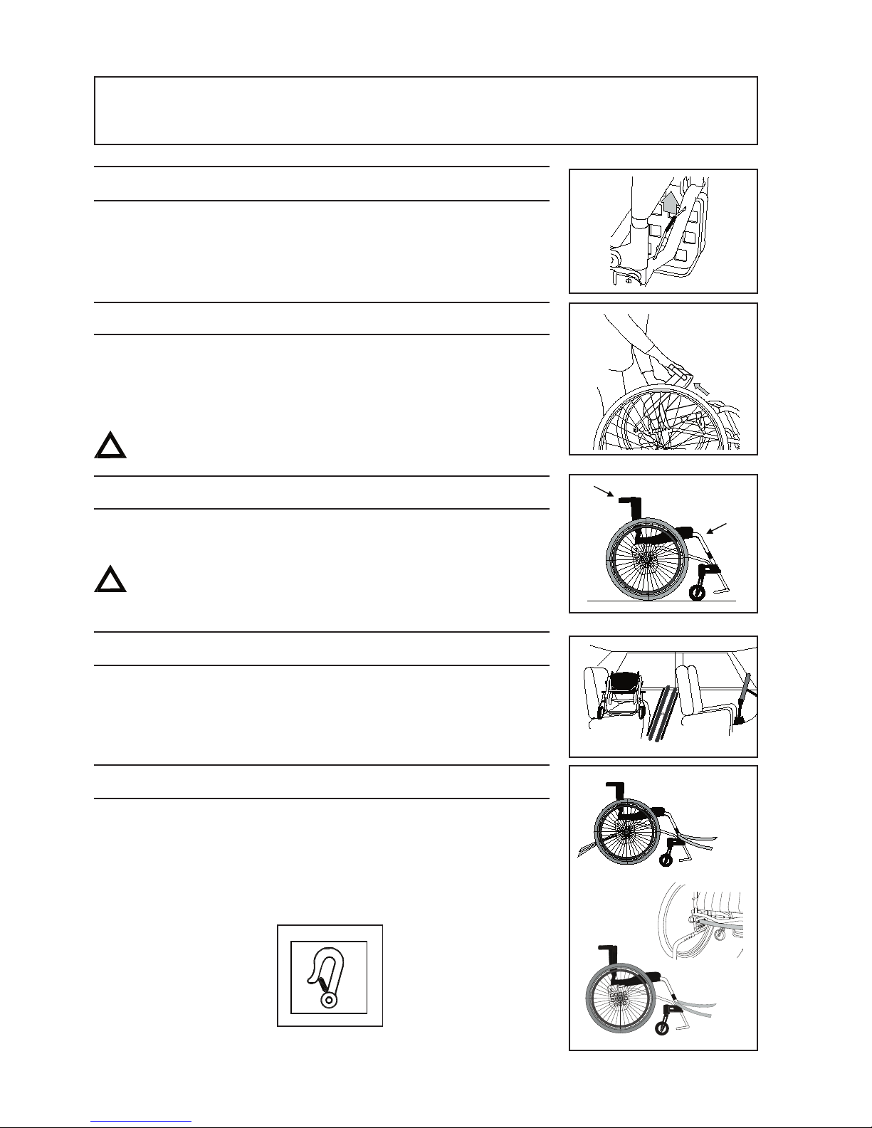
2:1 Folding
- If armrests or sideguards are mounted, they should be removed
- Remove the rear wheels
- Fold down the backrest by pulling upwards on the wire.
2:2 Unfolding
- Attach the rear wheels
- Fold up the backrest
- Attach armrests or sideguards if required
When attaching the rear wheels, ensure that they are securely
mounted. The button in the hub should pop out completely.
2:3 Lifting the wheelchair
- Lift by holding the push handles and the front part of the frame.
Before lifting, ensure that the push handles are securely
fastened.
2:4 Car transport
Private car/taxi: The wheelchair should be placed in the car boot.
If this is not possible, ensure that the wheelchair is placed in a seat in
such a way that it cannot roll or overturn.
If possible, the wheelchair should be secured using a safety-belt.
2:5 Securing
The wheelchair must be secured as follows. The straps must not run
through the wheels or around the seat back tubes.
2 HANDLING/TRANSPORT
Page 5
5
2 HANDLING/TRANSPORT
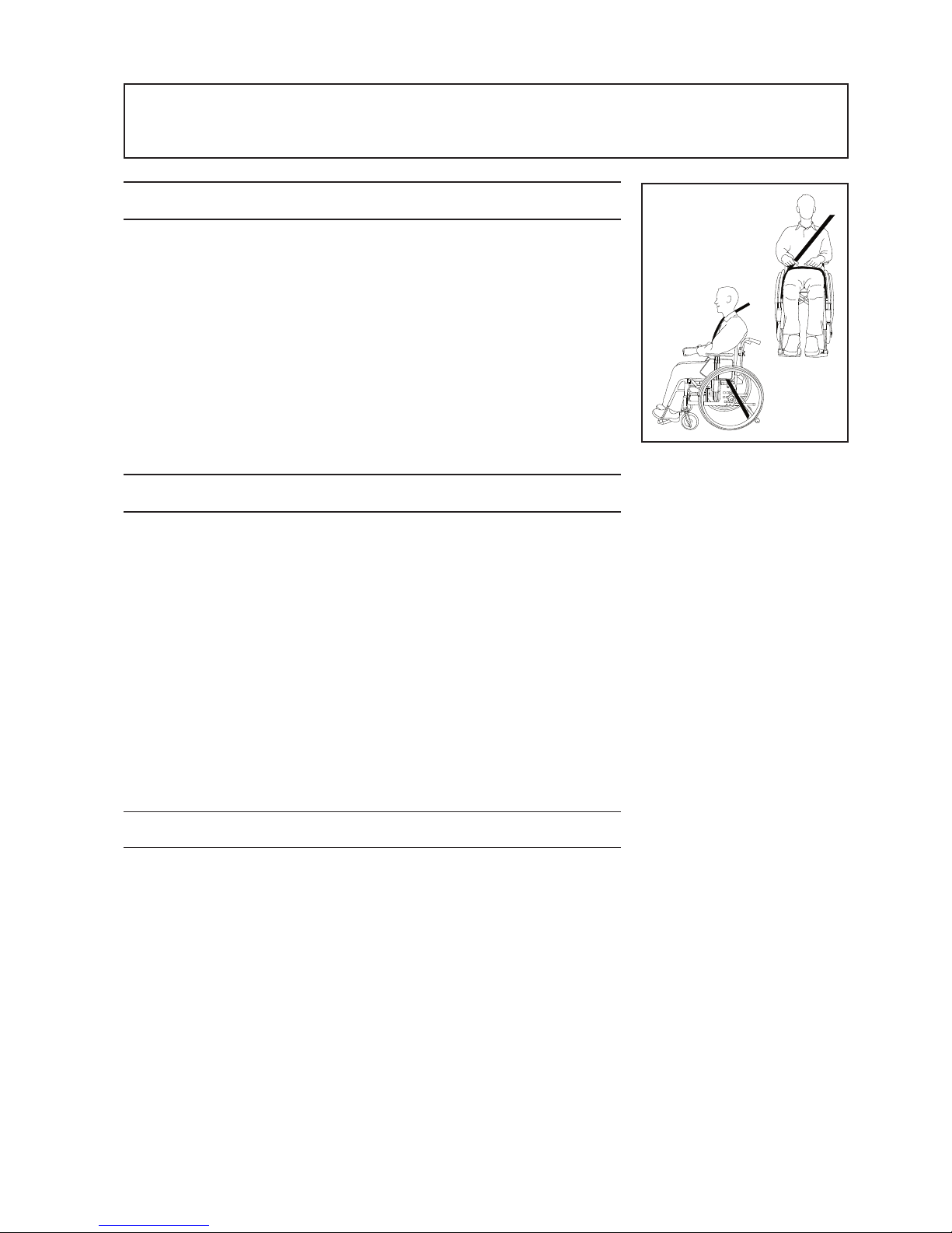
2:6 Seat belt
If the wheelchair is used as a seat for travelling in the vehicle Etac
recommends that the user wears the three-point seat belt that is fitted
to the vehicle. It is important that the three-point seat belt is fitted
correctly, as shown in the drawings:
2:7 Recommendations
Etac recommends that:
- the user transfers to one of the seat’s in the vehicle and wears the
vehicle’s three-point seat belt while travelling.
- a three-point seat belt is worn.
- positioning belt 25668 is used.
- a correctly adjusted headrest is used.
- the wheelchair is positioned facing forwards and is secured in
accordance with the instructions provided by the supplier of the
restraining device.
- the back of the wheelchair should be level with or above the user’s
shoulders when travelling in the vehicle.
- the parking brake is used and the anti-topple guard is lowered.
2:8 Warning'
- The wheelchair positioning
belt is inadequate to prevent the user
from being thrown out of the wheelchair in the event of
sudden braking.
- The restraining device must not pass through the wheels or
around the seat back tubes.
- Options/accessories that can be removed without tools, such as
trays, must be removed and secured or placed where they
cannot fly around inside the vehicle in the event of a collision.
- If a wheelchair was present in a vehicle that has been involved
in a collision it should be inspected at the local mobility
centre or by Etac before it is used again.
Page 6
6
3 PRODUCT DESCRIPTION STING
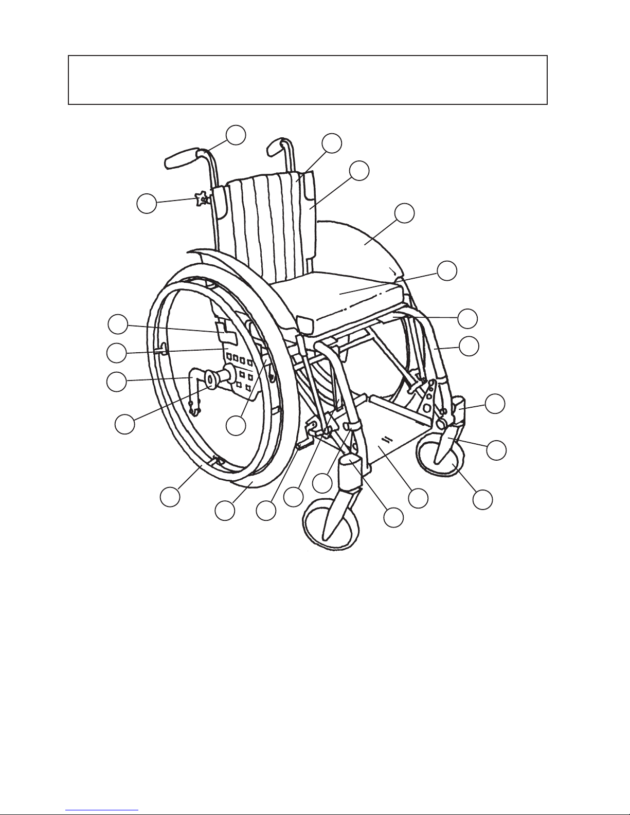
1 Push handles 13 Rear footrest attachment
2 Backrest cover 14 Cover
3 Backrest upholstery 15 Brake
4 Mudguard 16 22" rear wheel
5 Cushion 17 Stainless steel handrim
6 Seat upholstery 18 Rear axle
7 Frame 19 Quick-release hub
8 Front fork attachment 20 Anti-tip
9 Short front fork 21 Axle plate
10 All-round 5" castor 22 Back angle plate
11 Footrest 23 Locking knob, push handles
12 Footrest attachment
2
3
4
5
6
7
8
9
10
11
12
13
14
1516
17
18
19
20
21
23
22
1
Page 7

7
4 MODEL STING
STANDARD MODEL ALTERNATIVE MODEL (OPTIONS)
Seat adjustable in height and angle
Front seat height installed at 45 cm
5" All-round castors
Short front fork with 3 alternative height
settings for the castor
Rear seat height 43 cm
Seat depth 30 cm (5 cm upholstery tuck-in)
Rear wheels with quick-release hubs
22" high-pressure tyres.
Handrims: aluminium
Camber: 3°
Backrest adjustable in height and angle
Backrest height installed at 27 cm
Backrest angle installed at -3°
Adjustable backrest upholstery of velour and
plush
Push handles, height adjustable
Footrests, adjustable in height, depth and
angle
Rear attachment is a swivelling strap
Brakes: with long handle
Transparent mudguard
Cushion, grey plush, 35 cm long
Anti-tip adjustable in height and length
Seat adjustable in height and angle
Front seat height 43-52.5 cm
6.5" allround pneumatic castors
Medium front fork with 3 alternative heights
settings for the castor
Rear seat height 37-48 cm
Seat depth 25-35 cm
Rear wheels with quick release hubs
24" high pressure tyres; 20", 22", 24"
low-pressure tyres, or solid tyres.
Handrims: Stainless steel, friction coated,
cellular rubber or plastic coated.
Backrest adjustable in height and angle
Backrest height 25, 29, 31 ,33 and 35 cm
Backrest angle alternatives: 0°, 3°, -5°, -8°,-10°
Bow handle, adjustable in height.
Footrest adjustable in height, depth and angle
Rod for fixed positions (see accessories)
Armrest, sideguard (accessory)
Page 8
8
5 OPTIONS
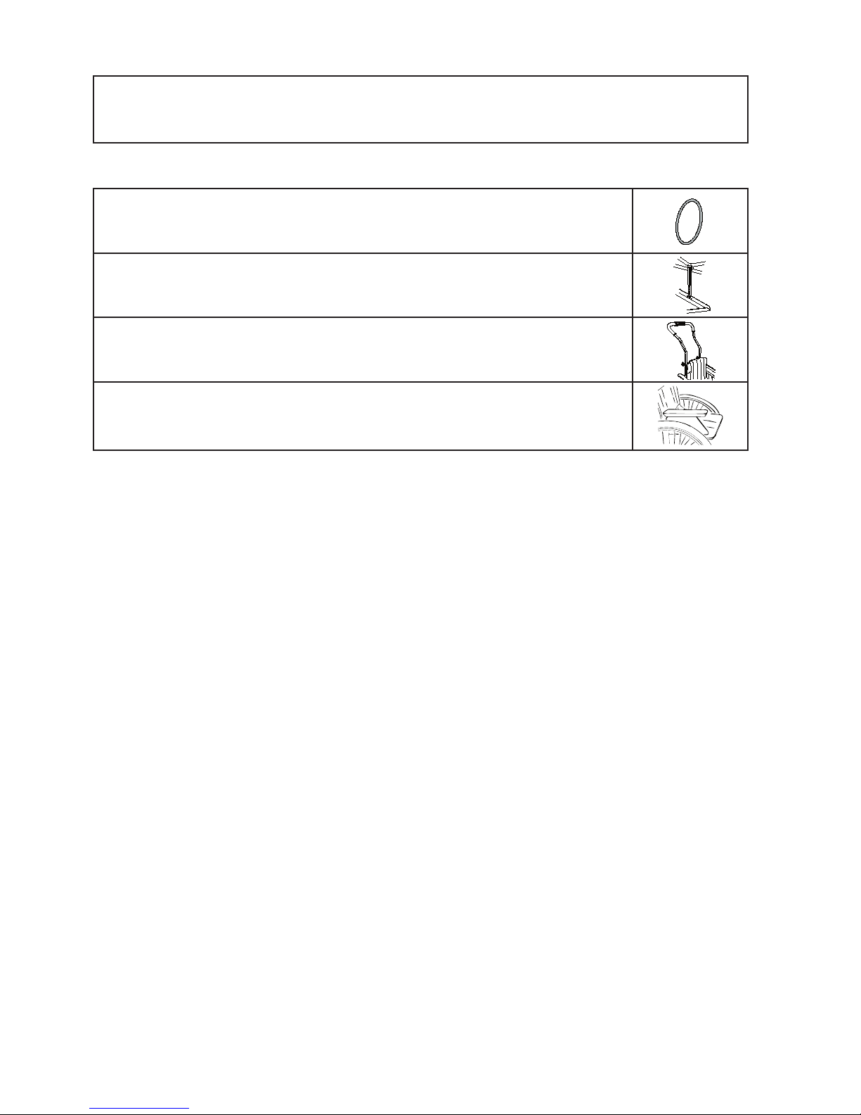
HANDRIMS cellular rubber, aluminium, friction-coated, stainless steel or grey
plastic coated.
FIXING ROD adjustable in length, fastened to the rear of the footrest
BOW HANDLE height adjustable, detachable
ARMREST height adjustable, 26 cm long, one-piece, black
Page 9
9
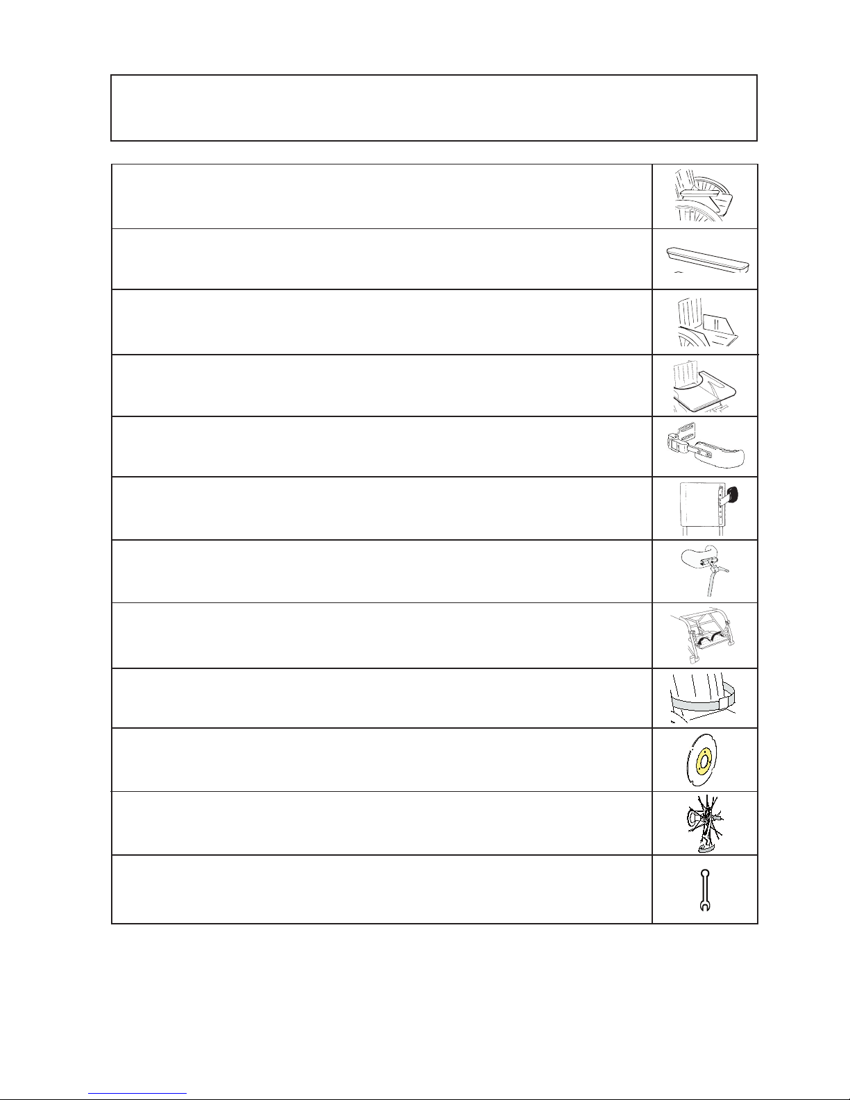
5 ACCESSORIES
*= only available for the swedish market
ARMREST height adjustable, 26 cm long, one piece, black
ARMREST CUSHION padded alt. gel, dark grey plush, detachable
SIDEGUARD hard, black
TRAY transparent (in combination with armrest)
TRUNK SUPPORT adjustable in height and depth, swing-away.*
TRUNK SUPPORT adjustable in height and depth
HEAD REST with angled attachment rod, adjustable in height, depth and angle.*
FOOT STRAP
SEAT BELT with snap lock
SPOKE GUARD with coloured logo
QUAD WHEEL RELEASE ADAPTER for those with reduced hand capacity
TOOL KIT
Page 10
10
6 SETTINGS SEAT
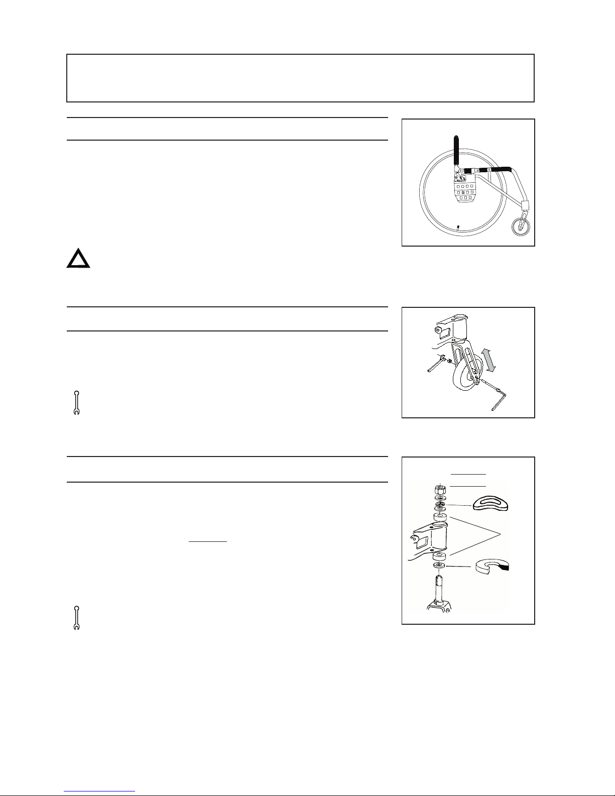
6:1 FRONT SEAT HEIGHT
The front seat height (adjustable between 43-52.5 cm) is dependant
upon:
Castor: 5", 6" or 6.5"
Front fork attachment: Adjustable in angle
Front fork: Short or medium with three alternative
height settings for the castor.
Risk for tipping: Always check the positioning of the
anti-tip.
(!) See also para 13: “Alternative seat heights/angles”.
6:2 Castor
The height can be altered by changing the castor itself or by changing
the position of the castor in the front fork. Unscrew the wheel and
replace it at the desired height in the fork.
Tools: 5 mm Allen key and 10 mm spanner
(!) Also adjust the angle of the front fork attachment, see para 6:4
6:3 Changing the front fork
Unscrew the protective stopper (1) on the front fork attachment to
reach the retaining nut (2). Unscrew the nut and pull out the front
fork. Take the washer from around the fork axle and put it on the new
fork (the bevelled side (A) towards the fork. It is important to make
sure that the washers in the attachment (under the retaining nut) are
placed in the right order, with the spring washer (B) in the middle.
Tighten the retaining nut until you cannot turn it any more, then
loosen it 1/2 a turn or so. The spring reduces the risk of wobbling.
Tools: 19mm spanner
(!) Also adjust the angle of the front fork attachment, see para 6:4
B
1
2
A
Lager
Page 11
11
6 SETTINGS SEAT
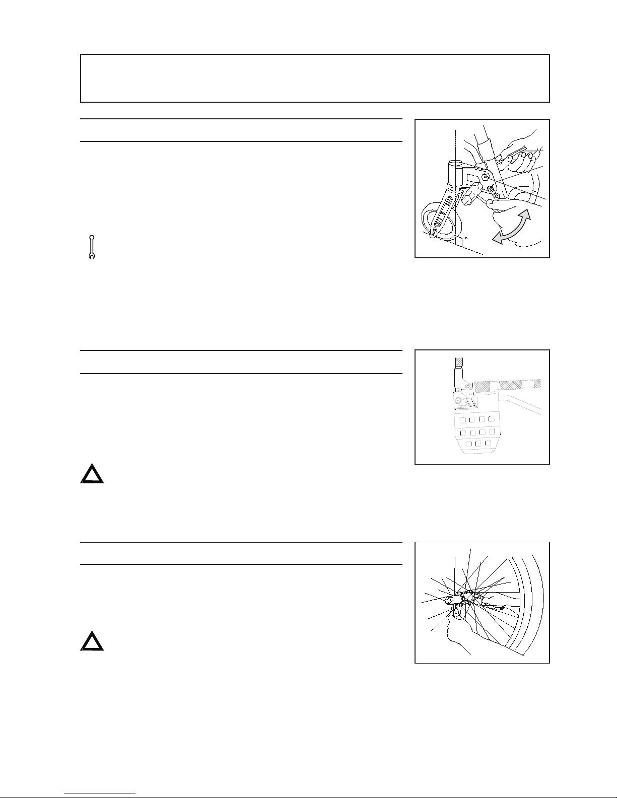
6:4 Setting the angle of the front fork attachment
Loosen the lower attachment screw (A) 1/2 turn and the upper screw
(B) 1/4 turn. Insert a small Allen key into the opening (C) at the edge
of the casing, and turn it until the attachment is at 90° to the floor.
Hold the casing in place with the Allen key while tightening the
upper and lower screws.
Tools: 6mm Allen key, and a smaller Allen Key.
(A spirit level may be useful)
(!) Keep your eye on something vertical, e.g. a table leg or
door post when adjusting the attachment.
This adjustment must be made when the seat height has
been changed at front or rear, or the manoeuvrability of the
wheelchair will be impaired.
6:5 REAR SEAT HEIGHT
The rear seat height is dependant upon:
The size of the rear wheels 20", 22" and 24"
The position of the rear wheels: 3 alternative heights: A-B-C
Risk of tipping! Always check the position of the anti tip
(!) See also para 13: “Alternative seat heights/angles”
6:6 Rear wheel with quick release hubs
The hub axle can be adjusted in length. Turn the nut on the axle
inwards/outwards whilst at the same time holding the axle with
a spanner.
When attaching the wheels, always check that they are
sitting securely. The button on the hub should pop out
completely.
C 41 cm
B 45 cm
A 48.5 cm
Position
Page 12
12
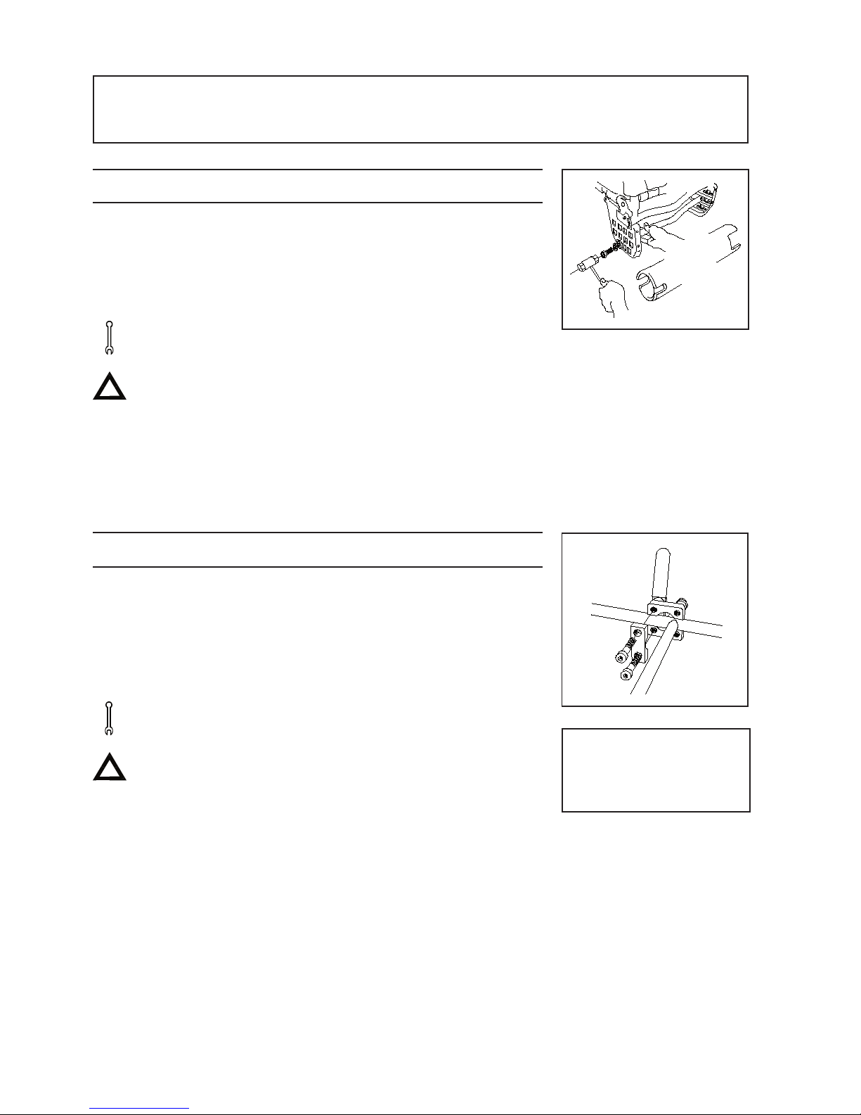
6:7 Height adjustment of the rear wheels
Unscrew the axle sleeves and washers, tilt the rear axle to free it, and
mount it at the desired height. Mount the rear axle with the larger
slots against the right-hand wheel attachment. At the same time as
you install the rear seat height, you should also check that you have
attained the correct centre of balance, see para 9:8.
Tools: 21 mm socket wrench
Check that the rear wheels are securely mounted, see para 6:6.
Always check the positioning of the anti-tip.
Always adjust the position of the brakes when changing the
installation of the rear wheels.
(!) Also adjust the angle of the front fork attachment.
6:8 Adjusting the brakes
The brakes are variably adjustable along the lower fram tube.
- Loosen the screew a couple of turns and slide the brake so
that the brake block sits about 20 mm from the tyre when
the brakes are off.
- Test the barkes!
Tools: 5 mm Allen key
The effectiveness of the brakes depends upon the amount
of air in the tyre.
The brakes are parking brakes only and shouldnever be
applied when the wheelchair is in motion.
6 SETTINGS SEAT
A brake handle extension
is available as an accessory,
see para 10:11
Page 13
13
6 SETTINGS SEAT
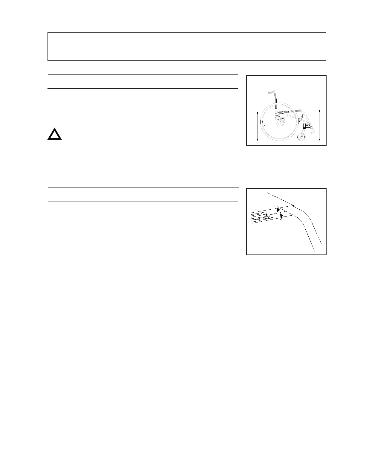
6:9 SEAT ANGLE
Seat angle is defined by the relationship between front and rear seat
height.
The seat angle is adjustable between 0-10° backward tilt (0-7cm)
Always remember the risk of tipping -adjust the setting
of the anti-tip,
(!) If the seat angle is changed :
- Adjust the angle of the front fork attachments
- Also check the backrest angle.
6:10 SEAT DEPTH
The seat depth can be adjusted between 25-35cm by folding in the
front part of the seat upholstery. For increased seat comfort, stretch
the front part of the seat by tightening the lacing under the front, and
loosening it at the rear.
(!) The functional seat depth can be up to 6-7 cm longer
depending upon the settings of the backrest upholstery,
see para 7:4.
Seatheight
front
Seatheight
rear
Page 14
14
7 SETTINGS BACKREST
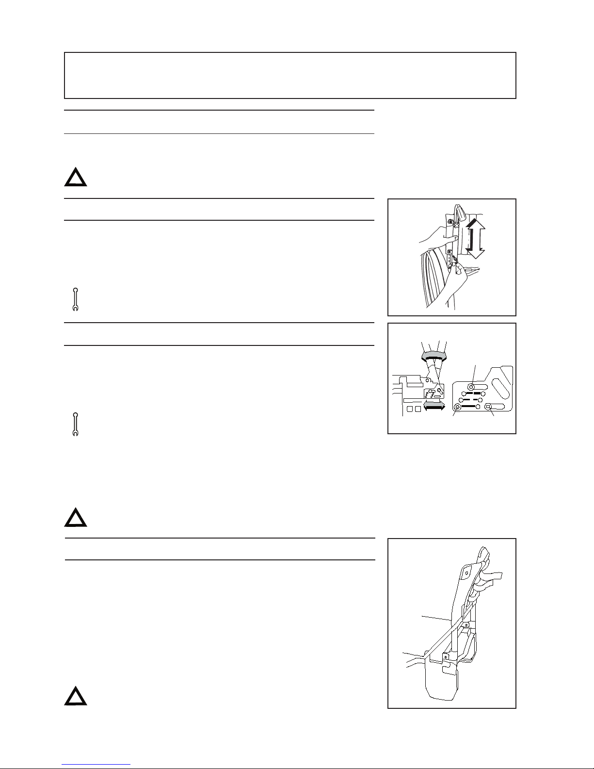
7:1 BACKREST
The backrest is adjustable in angle and has adjustable upholstery.
Risk for tipping! Always check the positioning of
the anti-tip when adjusting the backrest.
7:2 Backrest height
The backrest is telescopic and is adjustable between 25-35 cm. Unscrew
the lower screw, (A) and loosen the upper screw one turn on both sides.
Select the desired height. There are attachment points at 2 cm intervals.
Tighten the screws properly.
Tools: 4 mm Allen key; 6 mm Allen key, if required.
7:3 Backrest angle
The backrest angle has fixed positions at +3°, 0°, -3°, -5°, -8° and -10°
Unscrew (A) completely, loosen screws (B) one turn. Install the desired
height by tuning the screw (A) to the correct angle marker. Tighten the
screws again.
Tools: 4 mm Allen key.
(!) Fold the backrest down against the seat when adjusting the
angle.
Allow the backrest cover ample space between seat and
backrest.
Risk of tipping! Always check the positioning of the anti-tip
when adjusting the backrest angle.
7:4 Backrest upholstery
The form of the backrest upholstery can be adjusted by means of four
Velcro straps and the cover.
- Give the backrest cover ample space between the seat and
backrest, allowing the user to “sit in” against the backrest,
- Loosen all straps and ensure that the user is sitting as far back
in the seat as possible.
- Tighten the straps in such a way that they follow the contours
of the user’s back and give plenty of support to the lumbar region.
Risk for tipping! Always check the position of the anti-tip after
adjusting the backrest upholstery.
A
B
C
Page 15
15
8 SETTINGS FOOTRESTS
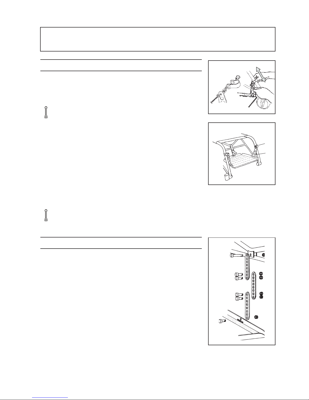
8:1 Adjusting the footrest in height, angle and depth
Height: Unscrew the screws on the frame tube.
Install the desired height by sliding the footrest
attachments up or down.
Tools: 5 mm Allen key
Angle: The angle can be adjusted by raising/lowering the
rear attachment strap.
Depth: The footrest can be moved forwards 4cm by turning the
attachments 1/2 a turn (A) so that the screws are in front
of the frame tube. The footrest can be moved even
further forwards by removing the base plate from its
attachments (B) and re-setting it in the desired position.
Please note that the footplate will tip forwards more
easily when it is moved forwards at (B). The rear
attachment strap can be complemented with an
attachment rod, (see 8:2).
Tools: 3 mm Allen key and 5 mm Allen key. 8 mm spanner.
8:2 Fixed rear mounting of the footrest (optional)
A rear fixing rod, adjustable in length, is available as an option for
the footrest.
- Adjust the length of the rod
- ttach the rod as illustrated
B
A
Page 16
16
9 SETTINGS: OPERATING CONDITIONS
9:1 OPERATING CONDITIONS
Weight distribution is the decisive factor when it comes to operat
ing conditions. It is in part dependant upon the user’s weight, size
and seating position in the wheelchair, and in part upon the position
of the rear wheels. The more weight that is placed above the rear
wheels, the easier the wheelchair is to manoeuvre. If more weight is
placed over the castors, the chair becomes heavier to drive. Sting is
delivered with a standard
3° camber. This means that the wheels are a little closer to the seat
and backrest at the top and are wider apart near the floor.
The advantages of this are that the wheelchair :
- turns more easily
- holds a steady course
- has a broader support base
allows the user to hold his/her arms closer to the body when moving
forwards- thus giving more strength to each push.
Assistant: If the user is left alone in the wheelchair, ensure that
the brakes are applied and the anti-tip is
swung down.
Parking: Increase the overall support base of the wheelchair
by reversing for about 10cm , thereby ensuring that
the castors swing forwards.
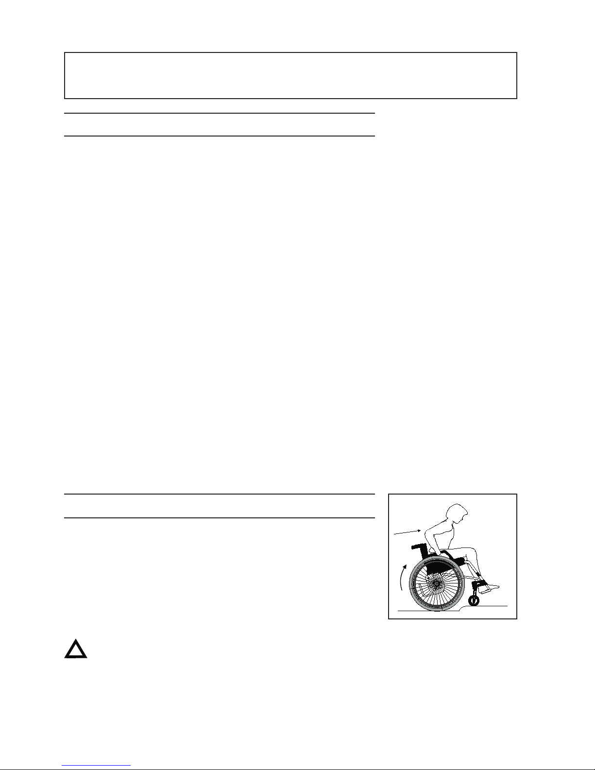
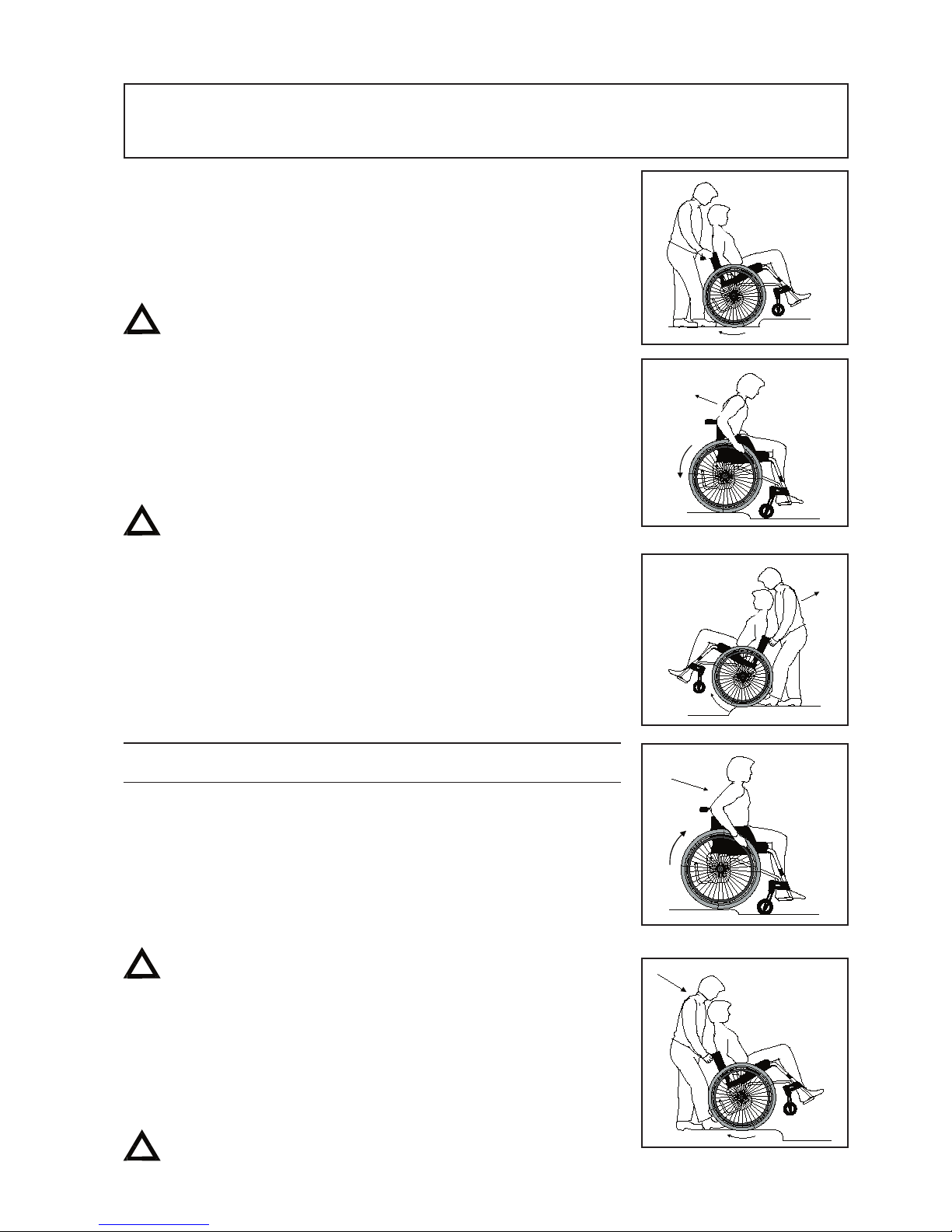
9:2 OPERATING CONDITIONS: Kerbs and raised thresholds:up
User alone, driving up forwards:
This method is recommended only for experienced wheelchair users.
- Ensure that the anti-tips are turned upwards.
- Drive forward to the edge of the kerb/threshold.
- Balance the wheelchair on its rear wheels so that the castors
lift off the ground high enough to clear the obstacle.
Push forwards firmly on the handrims while at the same time
leaning forward with your upper body.
Be sure to turn the anti-tip back to the down position.
Page 17
17
Assistant,driving up forwards:
- Ensure that the anti-tips are turned upwards.
- Tilt the wheelchair, with help from the tipper-bar, so that the
castors lift high enough to clear the obstacle.
- Lift by the push handles to help the rearwheels over the
obstacle.
Be sure to turn the anti-tip back to the down position.
User alone, driving up backwards:
This method works only if the obstacle is low, relative to the
installed height of the footrests.
- Ensure that the anti-tips are turned upwards.
- Reverse the chair until the rear wheels meet the obstacle.
- Push back firmly and strongly on the handrims while at the
same time leaning the upper body forwards.
Be sure to turn the anti-tip back to the down position.
Assistant, driving up backwards:
- Reverse the chair until the rear wheels meet the obstacle.
- Tilt the wheelchair with help from the tipper-bar so that the
castors are off the ground.
- Pull the wheelchair up and backwards, ensuring that the castors
have cleared the obstacle before setting down the chair onto all
four wheels.
Be sure to turn the anti-tip back to the down position.
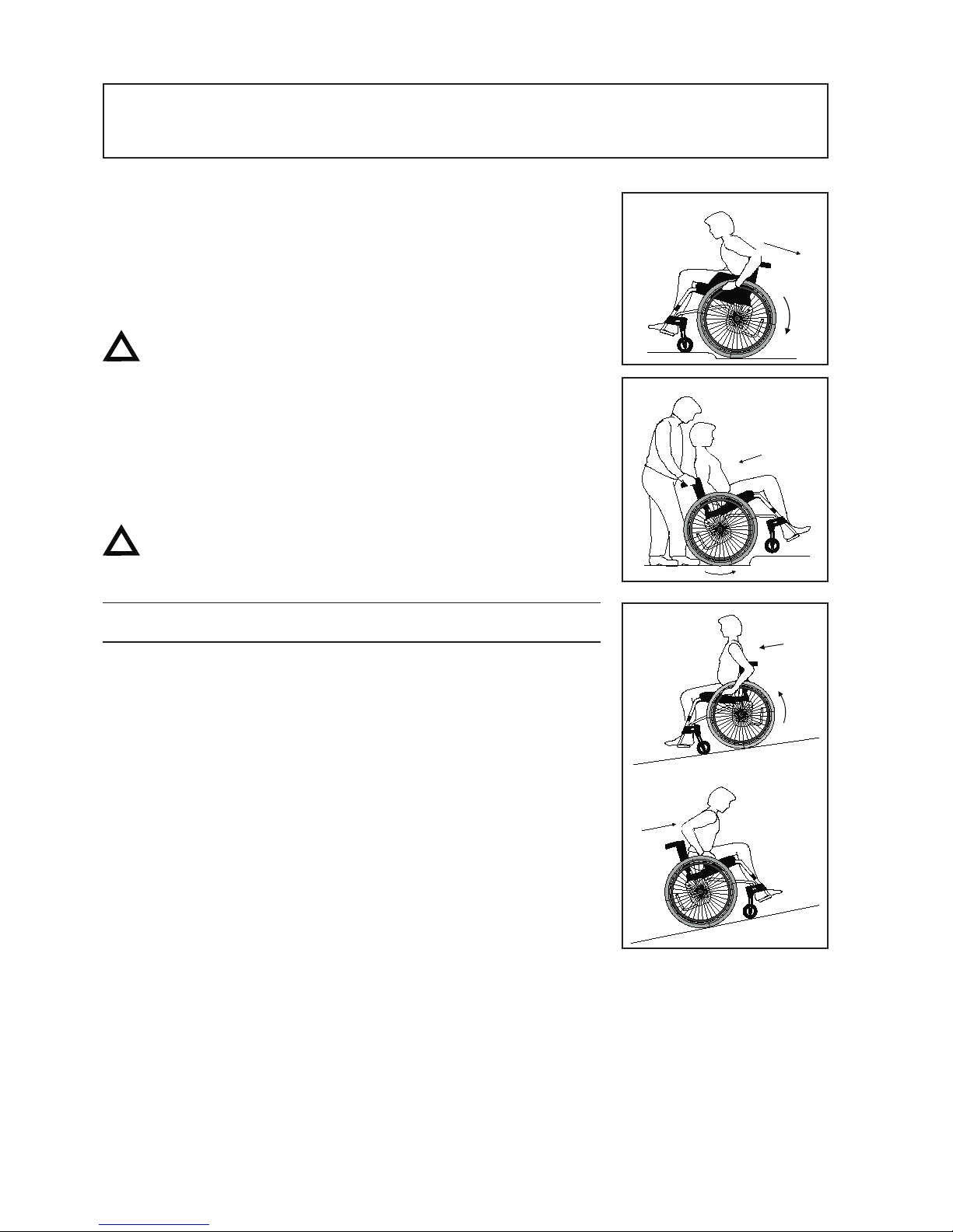
9:3 OPERATING CONDITIONS Kerb: down
User alone, drive down forwards:
This method is recommended only for the experienced wheelchair user.
- Ensure that the anti-tips are turned upwards.
- Drive forward to the edge of the kerb.
- Push forwards firmly and strongly on the handrims so that the
wheelchair lands below the kerb on all four wheels
simultaneously.
Be sure to turn the anti-tip back to the down position.
Assistant,drive down forwards:
- Ensure that the anti-tips are turned upwards.
- Tilt the wheelchair, with help from the tipperbar, so that the
castors clear the ground.
- Drive carefully down the kerb and set down the castors onto
the ground again.
Be sure to turn the anti-tip back to the down position.
9 SETTINGS: OPERATING CONDITIONS
Page 18
18
User alone,drive down backwards:
This method is not recommended for obstacles over 10 cm in height.
- Ensure that the anti-tips are turned upwards.
- Reverse the chair to the edge of the kerb.
- Reverse carefully down the kerb while at the same time
leaning forwards with the upper body.
There is a greater risk of tipping during this manoeuvre.
Be sure to turn the anti-tip back to the down position.
Assistant, drive down backwards:
- Ensure that the anti-tips are turned upwards.
- Reverse the chair to the edge of the kerb.
- Reverse carefully down the kerb and continue backwards,
keeping the castors raised until they have cleared the kerb.
- Set down the wheelchair onto all four wheels.
Be sure to turn the anti-tip back to the down position.
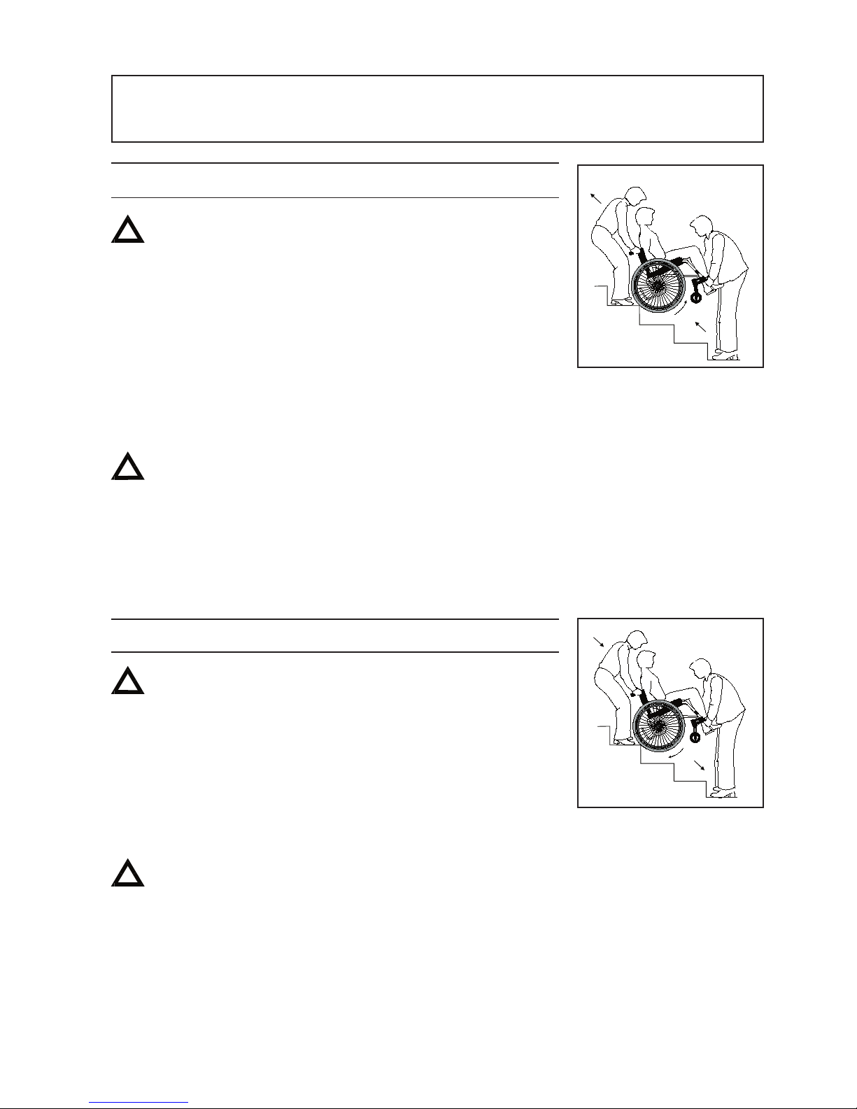
9:4 OPERATING CONDITIONS : Angled surface
Please read carefully this important advice for driving up or downhill
to minimise the risk of tipping.
(!) Never attempt a U-turn in the middle of a hill. Hold as
straight a course as possible. It is better to ask for help than
to take a risk on your own.
Uphill driving: Lean forward to correct your centre
of balance.
Downhill driving: Lean against the backrest to correct your
centre of balance. Control your speed
using the handrims; never attempt to
apply the brakes when in motion!
9 SETTINGS: OPERATING CONDITIONS
Page 19
19
9 SETTINGS: OPERATING CONDITIONS
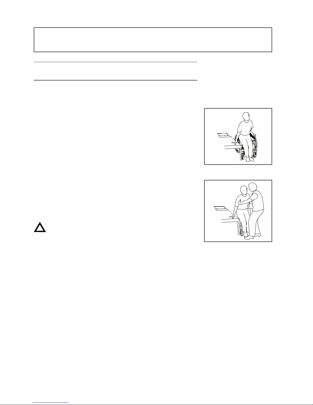
9:5 OPERATING CONDITIONS Staircase: up
Always ask for help.
Never use an escalator, even if you have an assistant.
With assistant, backwards:
- Turn the anti-tip upwards and ensure that height
adjustable push handles are securely fastened.
- Reverse the wheelchair to the first step.
- Tilt the chair onto the rear wheels, using the tipper-bar to help.
- Pull the wheelchair carefully upwards, one step at a time,
keeping the chair balanced on the rear wheels.
- When the last step has been cleared, continue backwards so
that the castors can be set down into contact with the ground.
Be sure to turn the anti tip back to the down position.
(!) If there are two assistants, one can help by lifting from in front
using lockable legrests, or by removing/swinging away the
legrests and lifting by the frame.
(!) Assistants should remember while lifting to keep their backs
as straight as possible.
9:6 OPERATING CONDITIONS Staircase: down
Always ask for help.
Never use an escalator, even if you have an assistant.
With assistant, forwards:
- Turn the anti-tip upwards.
- Drive forwards to the first step and tilt the wheelchair back
onto its rear wheels, using the tipper if necessary.
- Descend carefully one step at a time, keeping the wheelchair
balanced on its back wheels.
- After the last step set down the wheelchair onto all four wheels.
Be sure to turn the anti-tip back to the down position.
(!) If there are two assistants one can help by lifting from in front
using lockable legrests, or by removing or swinging away the
legrests and lifting by the frame.
(!) Assistants should remember while lifting to keep their backs as
straight as possible.
Page 20
20
9 SETTINGS: OPERATING CONDITIONS
9:7 OPERATING CONDITIONS
Transferring into/out of the wheelchair
The method for transferring a user into/out of a wheelchair should be
practised together with trained personnel. This paragraph should only
be used in an advisory capacity
With or without an assistant, sideways:
Before transference:
- Reverse the wheelchair 5-10 cm so that the castors are turned
fully forwards.
The wheelchair should be placed as near to the object of
transference as possible.
- Apply the brakes, remove or swing up armrest/ sideguard and
legrest on the side you intend to move across.
With or without an assistant, forwards:
Before transference:
- Reverse the wheelchair 5-10 cm. Be sure to turn the anti-tip
back to the down
- The wheelchair should be placed as position near to the object
of transference as possible.
- Apply the brakes and swing the legrests under the seat.
Never stand on the footrests !
(!) Assistants should remember while lifting to keep their backs as
straight as possible.
Page 21
21
9 SETTINGS: OPERATING CONDITIONS
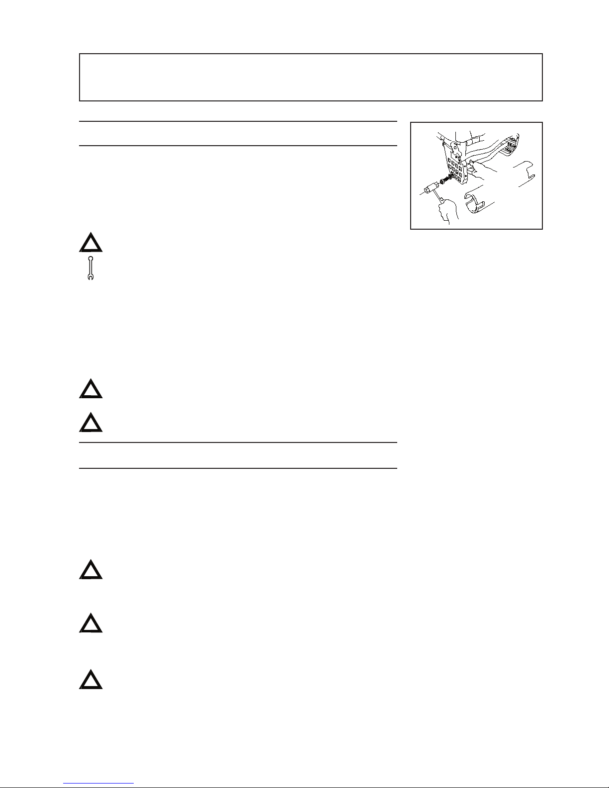
9:8 Centre of balance, adjustment
The centre of balance can be adjusted by changing the position of the
rear wheels.
- Remove the axle sleeve and washers and move the rear axle
backwards or forwards as described in para 6:7
Also adjust the brakes, see para 6:8
Tool: 21mm socket wrench.
When the rear wheels position is adjusted forwards the wheelchair
becomes easier to propel and turn, but the risk of tipping backwards
increases.
(!) The centre of balance is also changed when the seat angle
and/or backrest angle is adjusted.
We recommend that an anti-tip be used.
Check carefully that the rear wheels are securely mounted,
see para 6:6.
9:9 HANDRIMS
Sting is delivered as standard with aluminium handrims.
The way in which the user is able to grip the handrims is
influenced both by the type of handrim chosen, and its distance
from the wheel. Stainless steel, friction coated, cellular rubber
and plastic coated handrims are available as options.
The optional handrims give a better grip, but also increase
friction. It is therefore important to remember that when
stopping suddenly friction burns (i.e. blisters) may occur
Remember that when passing through a narrow space you
may pinch your fingers between handrim and wall. Also be
careful that your fingers do not slip into the spokes.
If there is a risk that fingers will catch in the spokes
recommend the use of spoke guards.
Page 22
22
9 SETTINGS: OPERATING CONDITIONS
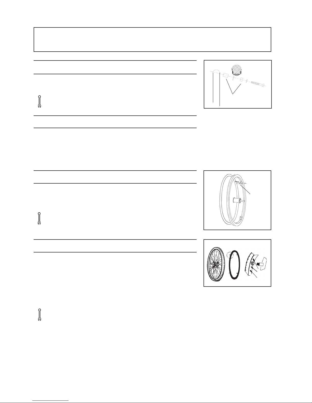
Spacers
9:10 Adjusting the distance of the handrim
The distance between the handrim and the wheel can be adjusted by
adding or removing spacers.
Tools: 4 mm Allen key
9:11 Handrims
Etac Sting is delivered with stainless steel handrims as standard.
To improve your grip on the handrim it may be necessary to adjust the
spacing between handrim and wheel.
Friction-coated and cellular rubber handrims are available as options.
9:12 Distance between wheel and handrim
The distance between the wheel and the handrim can be reduced
by removing the handrim from the wheel and shortening the plastic
spacers.
Tools: 10 mm spanner and hacksaw.
9:13 Mounting of cellular rubber handrims (option)
Cellular rubber handrims are attached directly to the spokes.
- Remove the existing handrim
- Unscrew the nuts on the cellular rubber handrim.
- Twist the handrim until each of the fasteners is attached to
a spoke.
- Tighten the nuts on the rear of the wheel. Be sure not to
over-tighten them as this may cause the spokes to bend.
Tools: 13 mm spanner
A
Page 23
23
10 ASSEMBLY INSTRUCTIONS: STANDARD ACCESSORIES
Assembly instructions are always provided with accessories when they
are delivered from Etac. They can also be ordered separately by contacting customer services.
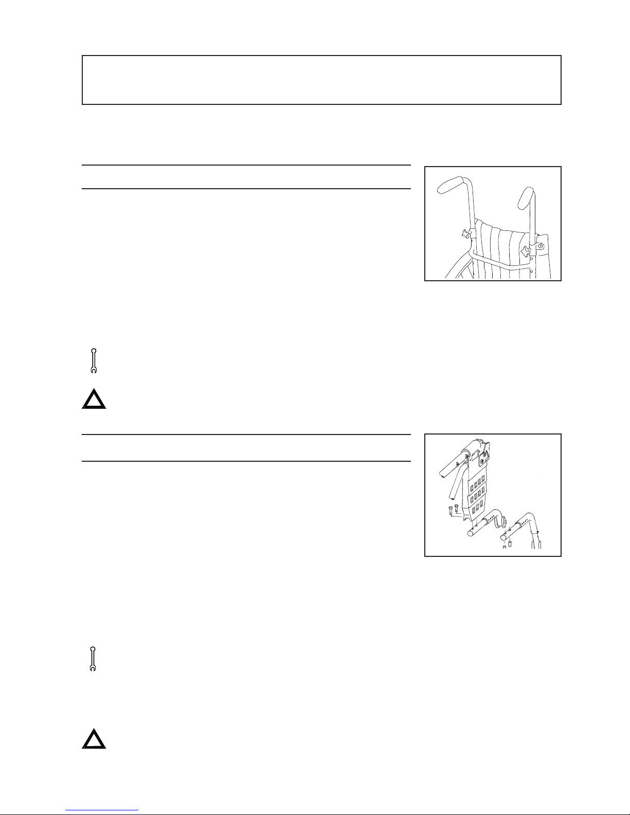
10:1 Height adjustable push handles
The push handles can be installed at 5cm intervals.
Remove the backrest upholstery. Fix the smaller of the attachment loops
to the backrest posts. Mount the upper push handle attachment to the
backrest posts and replace the upholstery. Fix the attachment tube for
the adjustable push handles into the upper attachment. Attach the larger
attachment loops to the attachment tubes. Secure by means of the
screws and nuts.
Now join the two attachment tubes together in the middle. Tighten all
screws and nuts. loosen the adjustment knobs on the attachment tubes,
install the desired height and re-tighten the knobs.
Tools: 4 mm, 5 mm, 6 mm Allen keys and 10 mm spanner.
Ensure that all screws and knobs are securely fastened.
This is especially important if you intend to lift the chair whilst
the user is in it.
10:2 Anti-tip
The anti-tip consists of four parts:
- The attachment bar is mounted under the wheel mount
(see illus.)
- The anti-tip bar snaps into the attachment bar at the desired
length.
- The extension with the stabiliser wheel is fixed to the anti-tip
bar at the desired height with a screw and nut.
To allow you to negotiate thresholds and the edges of thick carpets,
a distance of 3-4 cm from the floor to the stabiliser wheel is
recommended. For Etac Sting with 20" rear wheels fixed in the “C”
position, there is available a special anti-tip stabiliser with shorter bars.
Tools:4 mm Allen key, 8 mm spanner. 2 5 mm Allen keys for
fixing the anti-tip to the frame.
(!) The extended anti-tip bar is recommended when the rear wheels
are fixed in position “A”.
After adjusting the seat height, centre of balance or backrest
angle, the position and function of the anti-tip should always be
checked.
Page 24
24
10 ASSEMBLY INSTRUCTIONS: STANDARD ACCESSORIES
10:3 Mudguards
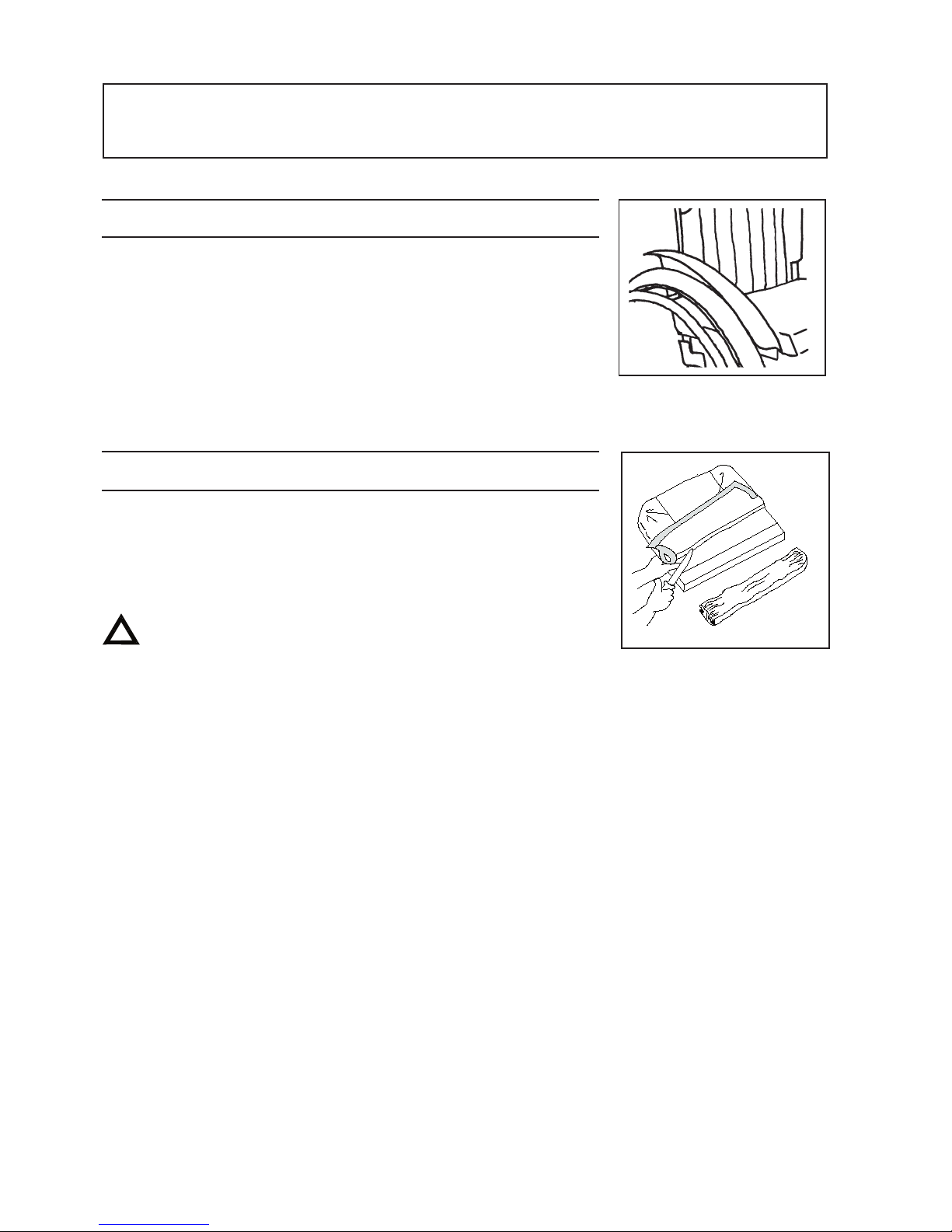
There are 3 different sizes of mudguard. Which you choose depends
upon the position in which the rear wheel is mounted : A, B or C.
The mudguards are adjustable so that the centre of balance of the rear
wheels may be adjusted in positions 1, 2, 3, or 4.
- There are two positions for mounting the attachment bar to
the mudguard.
- The mudguard can be extended ever further by turning the
fastening on the seat frame.
10:4 Cushion
The cushion is delivered 56cm long. It can be cut to the desired length
either at the front or rear. Ensure that the cushion is pushed back all
the way between the backrest posts, with the rounded corners at rear,
when measuring the length.
The cushion is a standard type and is not recommended
for users with sitting-sores
Page 25
25
10 ASSEMBLY INSTRUCTIONS: ACCESSORIES
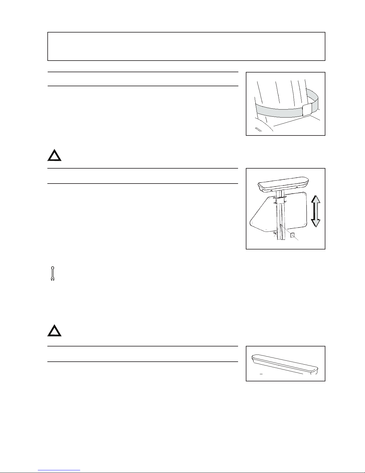
10:5 Seat Belt
The seat belt is adjustable in length and has a snap-lock.
Assembly instructions are provided.
(!) Ensure that the user does not glide forwards in the seat
as this can lead to blood circulation being impaired in
the midriff region.
The belt is to be used only for positioning in the wheelchair.
It must never be used as a substitute for a car safety belt.
10:6 Armrest, detachable, height adjustable.
The detachable armrest comes with short armrest supports.
The armrest attachment is adjustable between 17-24cm, with
1cm intervals. Detachable padded covers are available as options.
- Remove the screw from the side guard to release the
locking claque.
- You may now slide the side guard up or down to the
desired height.
- Re-screw the locking claque, ensuring that it securely fastened.
Tools: 3mm Allen key.
(!) The locking claque both secures the side guard and determines
the height of the armrest. If you wish the side guard to be
adjusted along with the height of the armrest, an extra locking
claque and screw may be ordered from us.
Never lift the wheelchair by the armrests.
10:7 Armrest cushion, padded
The padded alt. gel cushion can be fitted to the detachable armrest as
an accessory or can be ordered as an original option. It is made of dark
grey plush and is washable.
(!) The cushion raises the overall height of the armrest by
1.5-2cm.
Page 26
26
10 ASSEMBLY INSTRUCTIONS: ACCESSORIES
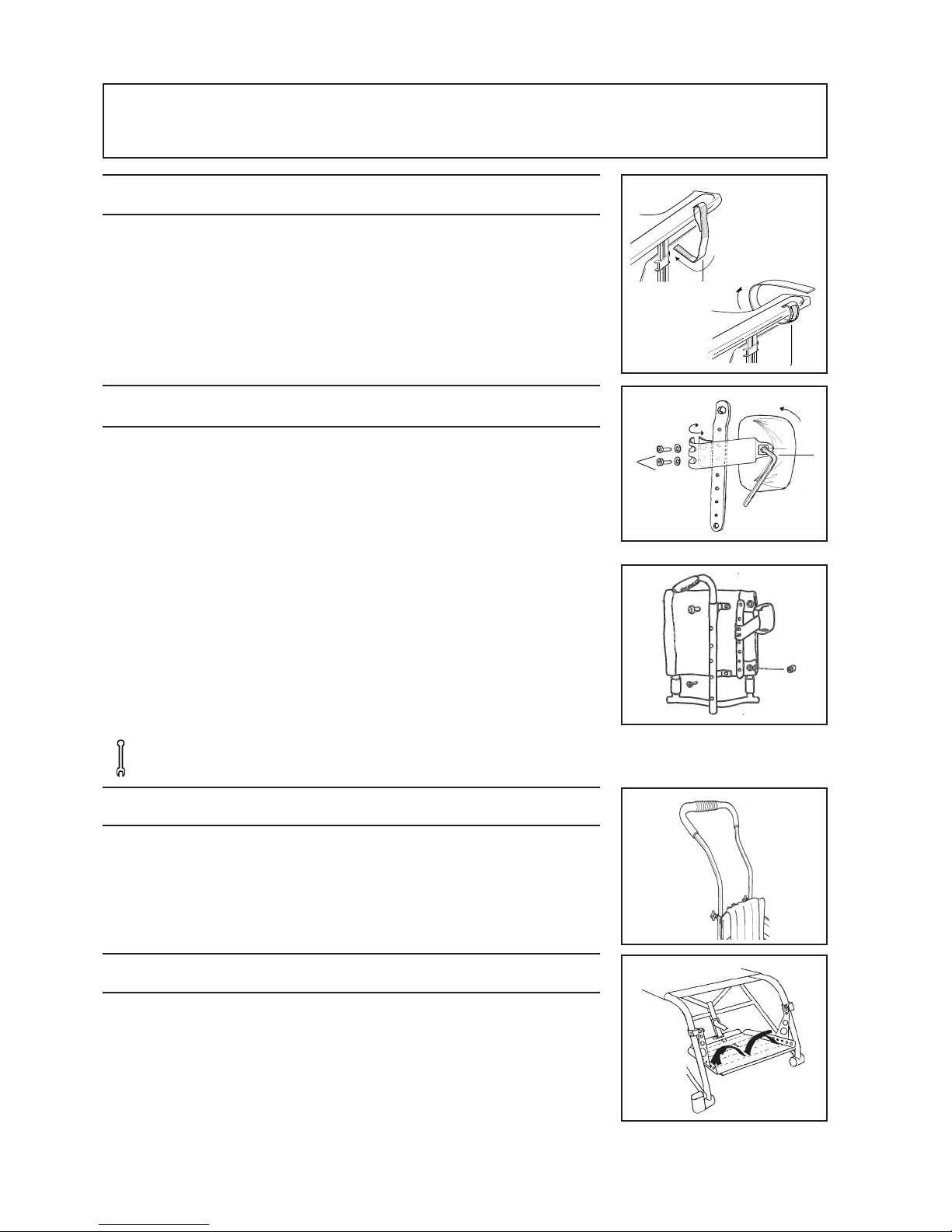
10:8 Mounting the tray
The tray is made of Plexiglas and is shaped to fit around the body.
It comes in three sizes and is mounted onto the armrests.
- Wrap the velour strap around the armrest (1) starting at the
outside and continuing ..
- down...
- and up the inside (2).
- Fasten by means of the Velcro on the tray.
10:9 Trunk support adjustable in height and depth
The attachment rod is fixed to the rear of the backrest between the
push handle and the height-adjustment screw.
If height adjustable push handles are being used, the trunk support
should be mounted closest to the backrest with the push handle
attachment at the outside.
The trunk support is adjustable in height, depth and angle.
Height: Attach the trunk support to the attachment rod
(2 screws A) at the desired height.
Depth: Loosen the screws (A) one turn and twist the trunk
support inwards or outwards. Re-tighten the screws.
Angle: Loosen the screw (B) which fixes the trunk support, and
twist the support to the desired position.
Re-tighten the screw.
Tools: 4 mm Allen key
10:10 Bow handle (option)
Remove the push handles from their attachment tubes. Insert the bow
handle, install at the desired height and tighten the knobs.
10:11 Foot loop
The footrest can be equipped with a foot loop if the feet need to be
held in place.
A
B
1
2
Page 27
27
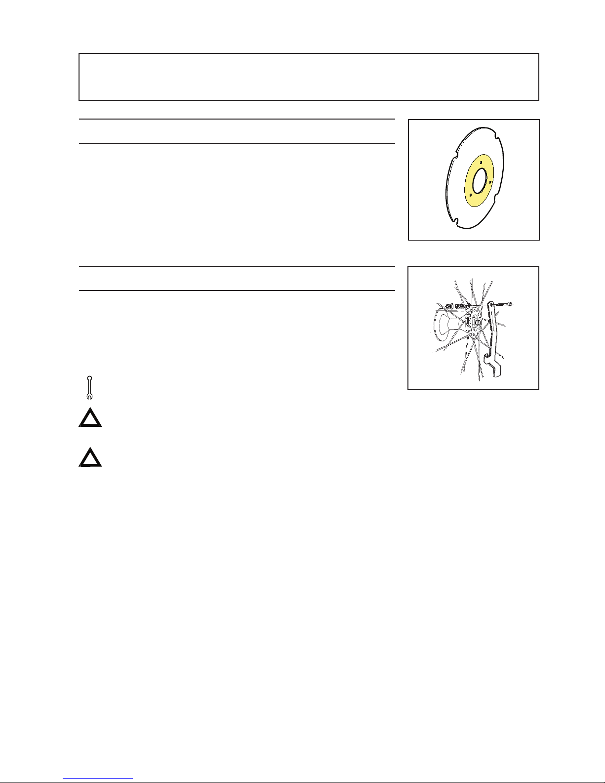
10:12 Spoke guard
The spoke guard prevents fingers from becoming caught in the spokes
and also gives some protection against splashing.
Assembly instructions are provided.
10:13 Quad wheel release adapter
Allows quick release of the rear wheels for individuals with reduced
strength in their hands or fingers.
It is also useful for relatives/assistants who need often to remove/
replace the wheels.
Assembly instructions are provided.
Tools: 8mm spanner and screwdriver
When the wheel is in position, the adapter can be moved aside
and fastened to a spoke with the hook.
After attaching the wheel, always ensure that it is securely
fastened. The button in the hub should pop out entirely.
10 ASSEMBLY INSTRUCTIONS: ACCESSORIES
Page 28
28
10 ASSEMBLY INSTRUCTIONS: ACCESSORIES
* Only for the Swedish Market
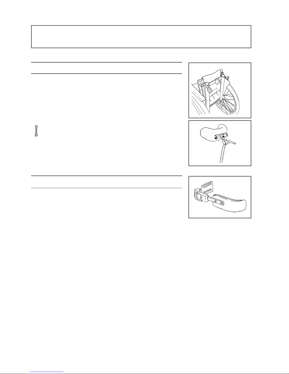
10:14 Head-reast mount*
The head-rest is adjustable in height, depth and angle.
Remove the backrest tubes by loosening the screws. Affix the headrest
and replace the backrest tubes. Slide the headrest support into place
and fasten at the required height using the screws.
(!) By turning the headrest support 180°, the attachment
can be mode even longer.
Tools: 6 mm Allen key.
10:15 Trunk-support adjustable in height and depth, swing-away*
Mount the trunk-support between the push-handle and mount on the
backrest post using the screws and washers supplied.
To swing the trunk-support to one side, simply lift and swing.
(!) The moving parts should be oiled regulary.
Page 29

29
11 CARE AND MAINTENANCE
UPHOLSTERY
The seat upholstery is made of two-ply polyester fabric and is attached to the seat frame by straps.
It can easily be removed by undoing the straps under the seat.
To remove the backrest upholstery, first take off the cover. Then remove the elastic strap and any
accessories, and pull the upholstery straight up.
The seat and backrest upholstery are machine-washable at 40°C.
REAR WHEEL/CASTOR FRONT FORK ATTACHMENT
Tyre/inner tube: Check the tyre pressure (see side of tyre) at least once a month; also check the tread.
Spokes: Loose spokes can lead to wheel wobble. Consult a cycle dealer or your wheelchair
supplier if you need to adjust the spokes.
Wheel axles: The axles should be kept free of dirt. Clean as necessary.
Ball bearings: The ball bearings require no maintenance.
Handrims: If a handrim should be damaged in such a way that it could lead to hand injury, it
should be replaced.
Front fork attachment: To achieve the best operating conditions, the attachments should be installed
at the correct angle. Check also that the front forks are tightened, see para 12:4.
BRAKES
The function of the brakes is dependant upon tyre pressure. Encrusted dirt can have a negative
effect on the brake mechanism. The brakes should be checked at least once a month. In the event of
adjustments see para 12:10
WASHING THE FRAME
Both for your own comfort and the longevity of the chair, it is important to keep the wheelchair clean.
Sting is easy to wash and keep clean. Wash the chair with car shampoo or washing-up liquid. If the
chair is particularly dirty, a grease remover can be used.
TOUCH-UP PAINT
Small bottles of touch-up paint, to repair scratches and chips, are available in all Sting colours.
MISCELLANEOUS
If there is a fault on your wheelchair you should contact your dealer at once. Defective chairs should
not be used. If your chair needs reconditioning or repair, only original Cross or parts of equal quality, as
specified in our diagrams, should be used. Etac will not be held responsible for damage or injury caused
by use of non-original parts.
(!) If necessary, lubricate moving parts/joints with cycle oil or similar.
Page 30

30
11 CARE AND MAINTENANCE
Problem* Solution
TROUBLE SHOOTING CHART
* The user may experience several of these problems if the wheelchair is incorrectly adjusted or is being incorrectly used
(!) If necessary, lubricate moving parts/joints with cycle oil or similar.
Wheelchair will not hold a straight
course
Wheelchair feel "heavy" to propel
Wheelchair feels "heavy" to turn
Brakes not effective
Rear wheels "loose"
Rear wheel hard to remove/replace
Castor "wobbles"
Wheelchair is hard to fold/unfold
Wheelchair feels "awkward"
- Inflate the tyres
- Check the front fork attachment angle
- Check that the front fork attachments are mounted
at the same height
- Rear wheel mountings are incorrectly fitted
- The user is distributing weight unevenly
- More strength being used on one side than the other
when propelling the chair
- Inflate the tyres
- Rear wheel mountings are incorrectly fitted
- Ensure that the castor axles are free from dirt etc.
- Too much weight over the castors. Adjust the centre of
balance
- Inflate the tyres
- Check that the fork attachments are not too tightly
fastened
- Adjust the anle of the front fork attachments
- Ensure that the castor axles are free from dirt etc.
- Too much weight over the castors. Adjust the centre
of balance.
- Inflate the tyres
- Adjust the distance between brake and tyre
- Ensure that the axle-shaft washer is in place
- Adjust the length of the axle shaft
- Clean and lubricate quick release with cycle oil or similar.
- Adjust the length of the axle shaft
- Front forks are not tightly fitted
- Check that the front fork attachments are mounted at
the same height
- Adjust the angle of the front fork attachment
- To much weight over the castors. Adjust the centre of
balance
- Upholstery are too tight
- Clean and lubricate the cross-brace under the seat
- Inflate the tyres
- Check that all screws, nuts and bolts are properly fastened
Page 31

31
12 TESTS and GUARANTEES
Sting is tested and approved for use indoors and out and is CE certified.
Max user weight is 50 kg
Handicap institute tests both functionally and technically. Test methods conform to ISO:s
norms, standard 7176
CE certifying: The product has passed all tests and met all criteria set by specific
productgroup European standards.
A proof that the product meets national and EU’s MDD (
Medical Device
Directive) standards.
Gives customers the chance to choose the best possible product by
comparing the test data.
Guarantee Frame: 5 years against material and/or constructional defects
Back/arm/footrest: 1 year against material and/or constructional defects.
Upholstery, wheels, spokes: No guarantee.
Specially adjusted chairs are those which are altered outside of the norms and standards contained
in the manual.
Wheelchairs specially adjusted by a customer cannot retain a CE
certificate. Etac’s guarantee no longer applies.
If in the least doubt about the validity of adjustments, please contact Etac
for advice.
Assemblage of Sting with another product, not manufactured by Etac:
Generally ensures the loss of CE certificate by both products.
Page 32
32
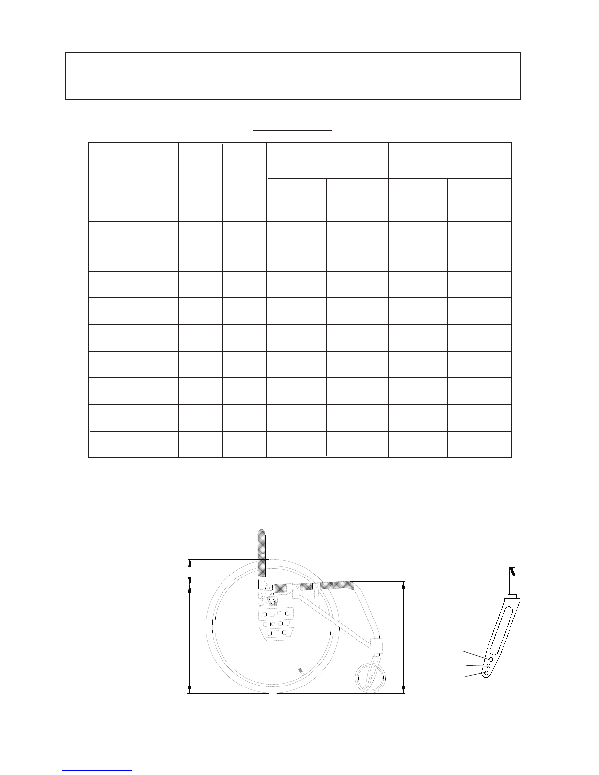
13 ALTERNATIVE SEATHEIGHTS/ANGLES
Seatheight
-front
Distance between seat
and 20" rear wheel
Seatheight
-rear
C
B
A
20" Rear wheel
1
2
3
4 3 2 1
C
B
A
Seat
height
rear cm
Seat
height
front cm
Distance
seat-rear
wheelcm
Seat
angle
5" Castors
Rear wheel Front fork
position position
C-B-A 1-2-3 C-B-A 1-2-3
37
37
37
41
41
41
44.5
44.5
44.5
37
39
41
41
43
45
44.5
46.5
48.5
15
15
15
11
11
11
7
7
7
0°
3°
6°
0°
3°
6°
0°
3°
6°
_
_
_
_
B 1-4
B 1-4
A 1-3
A 1-3
A 1-3
_
_
_
_
Short-1
Short-2
Short-1
Short-3
Medium-1
_
_
_
_
_
_
_
Rear wheel Front fork
position position
A 1-3
A 1-3
6.5" Castors
Short -2
Short-3
Page 33
33
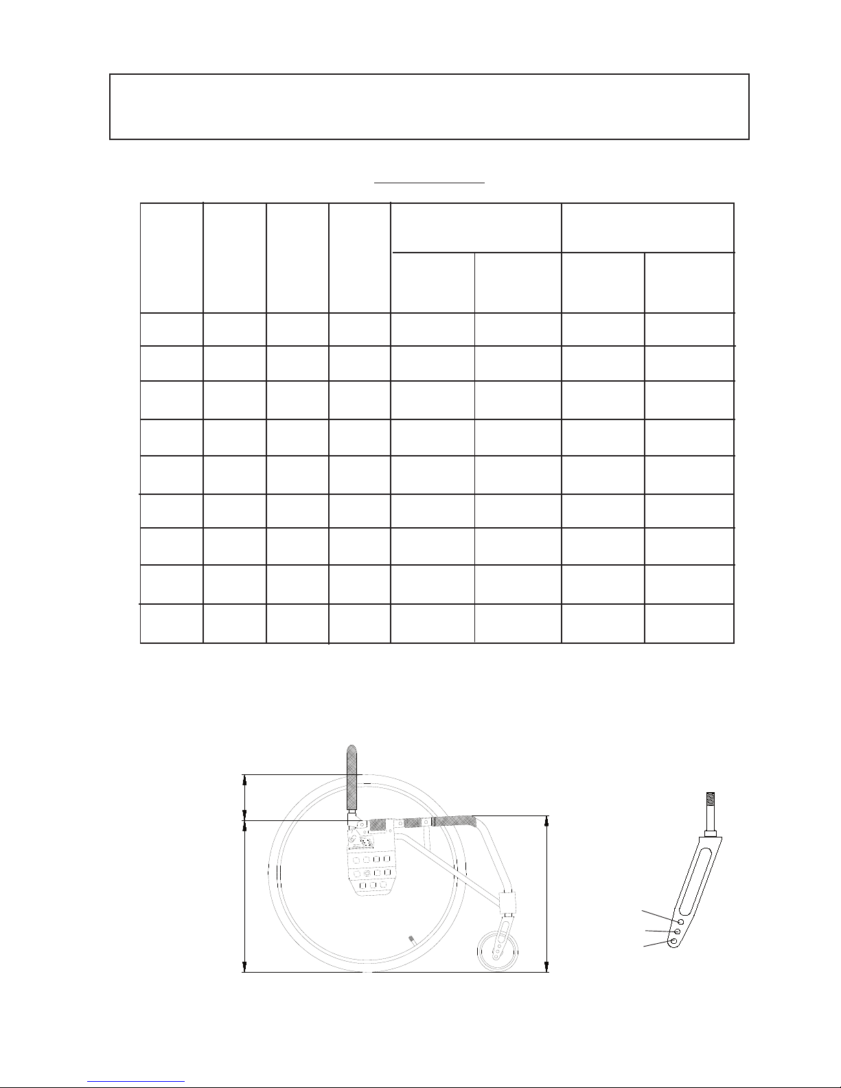
13 ALTERNATIVE SEATHEIGHTS/ANGLES
Distance between
seat and 20" rear
wheel
Seatheight
rear
4 3 2 1
C
B
A
22" Rear wheel
C
B
A
Seat
height
rear cm
Seat
height
front cm
Distance
rear
wheel
seat cm
Seat
angle
5" Castor
Rearwheel Fork Rearwheel Fork
position position position position
C-B-A 1-2-3 C-B-A 1-2-3
40
40
40
44
44
44
47.5
47.5
47.5
40
42
44
44
46
48
47.5
49.5
51.5
17.5
17.5
17.5
13.5
13.5
13.5
10
10
10
0°
3°
6°
0°
3°
6°
0°
3°
6°
_
_
C 1-4
B 1-4
B 1-4
B 1-4
A 1-3
A 1-3
A 1-3
_
_
_
_
_
_
_
B 1-4 Short -2
A 1-3 Short -3
A 1-3 Short-3
A 1-3 Medium-2
Short-1
Short-1
Short-2
Medium-1
Short-3
Medium-1
Medium-3
6.5" Castor
Seatheight
-front
1
2
3
Page 34
34
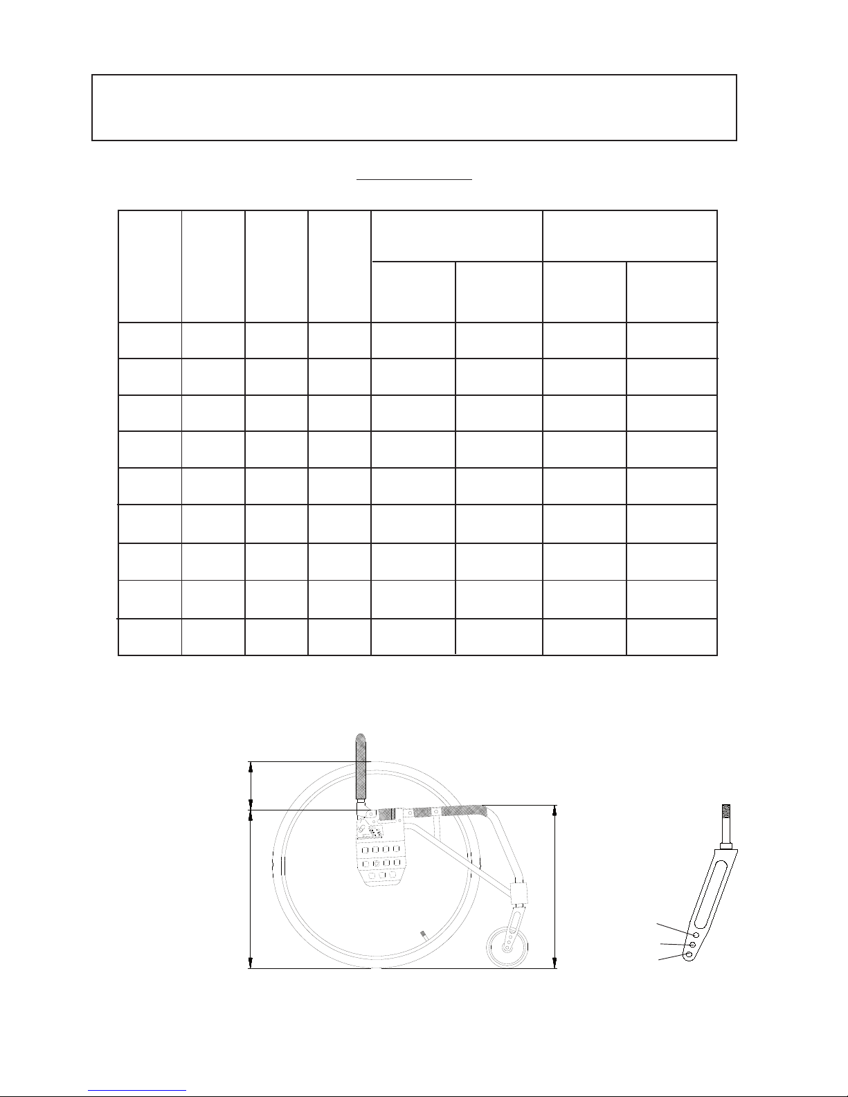
13 ALTERNATIVE SEATHEIGHTS/ANGLES
Seatheight
rear
C
B
A
24" Rear wheel
C
B
A
4 3 2 1
Distance between
seat and
24" rearwheel
Seat
height
rear cm
Seat
height
front
cm
Distance
rear
wheel
seat cm
Seat
angle
5" Castor
Rearwheel Fork Rearwheel Fork
position position position position
C-B-A 1-2-3 C-B-A 1-2-3
41
41
45
45
45
45
48.5
48.5
48.5
41
43
45
45
47
49
48,5
50.5
52,5
19
19
15
15
15
15
11
11
11
0°
3°
6°
0°
3°
6°
0°
3°
6°
C 1-4
C 1-4
B 1-4
B 1-4
B 1-4
B 1-4
A 1-3
A 1-3
A 1-3
_
Short-1
Short-2
Short-1
Short-3
Medium-1
Medium-1
Medium-2
Medium-3
_
_
_
_
6.5" Framhjul
B 2-4 Short -2
B 3-4 Short-3
A 2-3 Short-3
A 2-3 Medium-1
A 2-3 Medium-2
Seatheight
-front
1
2
3
Page 35
35
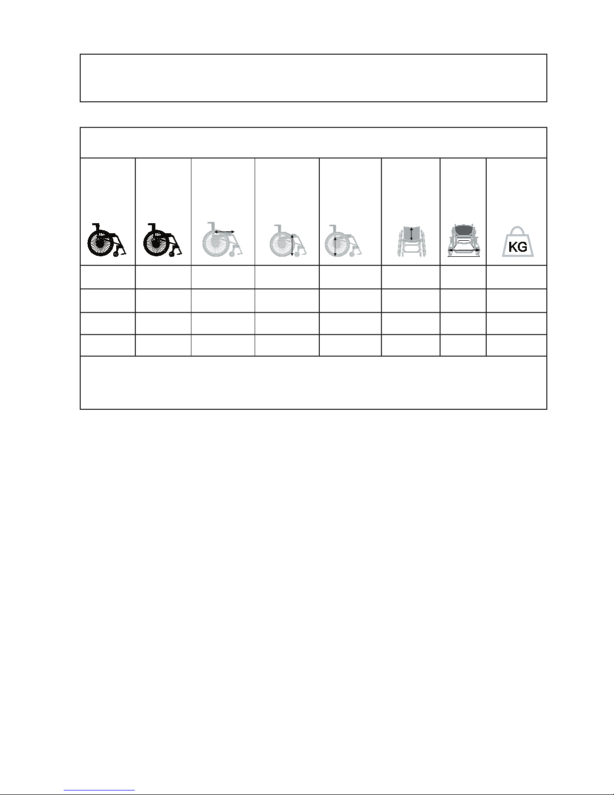
14 WEIGHTS AND DIMENSIONS, STANDARD MODEL
STING
Chairtype
Art. nr Seat depth front Seat height front Seat height back Backrest height Total width Weight without
backrests without cushions without cushion rear wheels
27.5 cm
30 cm
32.5 cm
35 cm
13110201-
13110202-
13110203-
13110204-
25-35 cm
25-35 cm
25-35 cm
25-35 cm
43-52.5 cm
43-52.5 cm
43-52.5 cm
43-52.5 cm
37-48 cm
37-48 cm
37-48 cm
37-48 cm
25-35 cm
25-35 cm
25-35 cm
25-35 cm
38 cm
40.5 cm
43 cm
45.5 cm
8.3 kg
8.4 kg
8.5 kg
8.6 kg
Colour choice for frame: 01= black, 02= red, 22= grey texture, 31= steel blue, 32= olive green, 33= sea green texture,
34= plum texture
Given measurements can vary +/- 1 cm
 Loading...