

Page 1

75341F 2018-10-18
Etac Prio
Manual
Applies to Etac Prio with serial no
beginning with 38C
Page 2

2
Etac / Prio / www.etac.com
Content
1. General - introduction
Intended use ............................................................................ 3
2. Description
................................................................................................ 4
3. Chair options
............................................................................................. 5-7
4. Accessories
............................................................................................. 8-9
5. Installation upon delivery
Back support ......................................................................... 11
Head support ........................................................................ 12
Push handles/Bow handle .................................................... 12
6. Charging
.............................................................................................. 13
7. Settings
Seat height ............................................................................ 14
Seat height adjustment using the rear wheel position ....... 14-15
Height adjustment, front ....................................................... 15
Height adjustment using the castor wheel's position
in the fork .............................................................................. 15
Height adjustment, front, by replacing the front fork/castor
wheel .................................................................................... 16
Disassembly/assembly of the front fork ................................. 16
Seat height table ................................................................... 17
Seat height adjustment using the attendant brake ................. 18
User manual
......................................................................................... 19-36
Symbols and warnings ........................................................... 20
Seat comfort settings ........................................................ 21-23
Handling ........................................................................... 24-29
Driving technique, use ...................................................... 30-32
Transport in vehicles ............................................................... 33
Removal of upholstery .......................................................... 34
Troubleshooting form ............................................................. 35
Transportations in aeroplanes ................................................. 36
Maintenance .......................................................................... 36
7. Settings (continued)
Back support height adjustment ............................................. 37
Seat depth - front .................................................................. 38
Seat depth - rear ............................................................... 39-41
Screw positions for seat depth ............................................... 42
Adjustment of comfort lock .................................................. 43
8. Readjustments
Brake, Adjustment ................................................................. 44
Brake lever adjustment .......................................................... 44
Brake, mounting and adjusting adapter ................................. 45
Adjustment of the centre of balance ...................................... 46
Amputee leg support ............................................................. 46
Elevating leg support with calf support .................................. 47
Anti-tips ................................................................................. 47
9. Accessories - adjustment, handling
Positioning belt ...................................................................... 48
Trunk support ....................................................................... 49
10. Technical data
.............................................................................................. 50
11. Tests and Guarantees
.............................................................................................. 51
12. Service and maintenance
Washing back support and seat ............................................. 51
Rear wheel/castor .................................................................. 51
Brakes .................................................................................... 51
Washing the frame ................................................................ 51
Touch-up paint ...................................................................... 51
Miscellaneous ........................................................................ 51
Page 3

3
Etac / Prio / www.etac.com
1. General
Thank you for choosing a wheelchair from Etac. The manual must be
read thoroughly to avoid damage when handling and using
the product.
In this manual, the User is the person sitting in the chair.
The Carer is the person helping the user.
Information on how people with impaired vision can access the
manual can be found in our presales guide at www.etac.com.
This symbol appears in the manual together with text.
It highlights actions where the wheelchair’s, the user's
or the care giver’s safety can be put at risk.
This symbol appears in the manual together with text.
Here you can find advice and tips worth considering.
Allen key
3, 4, 5, 6 mm
Ring spanner
8,10,13,
17, 24 mm
Socket spanner
19 mm
In the middle of this manual, you will find
a removable section containing user information.
Bear in mind the risk of tipping. Always use the anti-tips!
Etac Prio is intended for users who require high levels of comfort,
support and relief in different seated positions. Prio is often used by
users with a need for assistance from carers to move and transfer to
and from the wheelchair. Prio can be used both
indoors and outdoors.
Prio must be fitted by qualified personnel so that the user has a correctly equipped wheelchair in terms of size, settings and accessories.
Prio must be adjusted in the event of changes to
the user's needs.
Prio must not be used by people whose body size or weight does not
correspond with the size and weight restrictions applicable
to the chair.
There are no known contraindications.
Intended use
Tool
Etac continuously makes improvements to its products.
We therefore reserve the right to modify the products
without prior notice. The dimensions given on drawings
or other material are solely for guidance.
We cannot be held responsible for any printing errors or omissions.
Page 4

4
Etac / Prio / www.etac.com
22
4
1
15
16
17
18
19
10
24
6
23
28
2
25
27
5
7
8
9
11
12
13
14
20
21
3
26
30
31
29
32
33
1. Head support
2. Controls - back angle
3. Push handles
4. Locking knob, push handle
5. Back support
6. Rear wheel
7. Handrim
8. User brake
9. Quick release hub
10. Anti-tips
11. Chassis
12. Front fork attachment
13. Front fork
14. Castor wheel
15. Back cushion
16. Arm supports
17. Seat cushion
18. Calf pad
19. Leg supports
20. Knob footplate lock
21. Footplate with heel straps
22. Serial number label
23. Tilt controls - tilt
24. Dynamic pelvic support
25. Tool - Allen key 3 mm
26. Tool - Allen key 5 mm
27. Snap lock - head support
28. Trunk support attachment
29. Hand control
30. Charging socket
31. Seat angle actuator
32. Back angle actuator
33. Battery pack and control unit
2. Description
Page 5

5
Etac / Prio / www.etac.com
Seat height
38-52.5 cm
With 20", 22" or 24" rear wheels
40-45 cm
With 16" wheels
Seat angle
Max. forward angle: 3°
Max. backward angle: 20°
See also Comfort lock
Castor wheel
150x35 mm, semi-solid
165x30 mm, solid
200x35 mm semi-solid
200x50 mm, semi-solid
Front fork
Short (three height settings for castor wheels)
Medium (three height settings for castor wheels)
Rear wheels
16", width: 42 mm, solid tyres (no handrim)
20’’, width: 32 mm, solid tyres
22’’, width: 32 mm, solid tyres
24’’, width: 32 mm, solid tyres
Handrims
Aluminium
Camber
0°
Seat cushion
Basic: lightly contoured, cold foam
Plush or hygiene cover
Comfort: lightly contoured, cold foam with a soft memory foam insert in the
seat area.
Plush or hygiene cover
Back support
angle
0° - +30°
Seat depth
Three alternative positions
with separate intervals.
Standard setting:
Position 2
Position 1: 39-46 cm (short cushion)
Position 2: 41.5-48.5 cm (short cushion)
Position 3: 44-51 cm (short or long cushion)
Soft head support
Anatomic cushion, conforms to the neck when resting. Height and depthadjustable
Plush or hygiene cover
In the "Chair options" section you can see all configurations available for the wheelchair. For more information about chair options, see www.
etac.com
Settable= Adjusted using tools. Adjustable= Adjusted without tools.
3. Chair options
Page 6

6
Etac / Prio / www.etac.com
Head support,
angle-adjustable
Curved cushion with soft padding, height,
depth, side and angle-adjustable.
Plush or hygiene cover
Curved cushion with side support and soft padding. Height, depth, side and
angle-adjustable. Hygiene cover
Attachment for
angle-adjustable
head support
Angled attachment 45°
Back height
Height-settable: 55-70 cm
Back support
upholstery,
Comfort
Adjustable Velcro straps. Dynamic pelvic support, height-settable
3D back system
Complete back system adapted for kyphotic users. Height-settable: 45-60 cm.
Vertical and horizontal shape is created based on the user's back curvature.
Recommended in combination with angle-adjustable head support.
Back support
cushion/Back
support cover
Plush or hygiene cover
Soft cover. Plush.
Comfort lock
Four optional modes. Provides the carer with clear
instructions as to the mode that has been prescribed
as the most frequent rest mode. Not in combination
with electric recline function
0° seat tilt
4° seat tilt
8° seat tilt
12° seat tilt
Electrical recline
function
Electrical recline of seat and back angle Operated by means of hand control.
Limitations: Not with comfort lock, dynamic pelvic support, QR-pin for back
support, oxygen holder/transport basket, clips angle restriction.
Push handle/
Bow handle
Height-adjustable in 2 cm
intervals.
Push handles
Bow handle
Bow handle, angle-adjustable (not available for
55 cm wide chairs)
Leg support
Elevating
Six fixed positions. With padded kneepads and folding calf supports, height,
angle and depth-settable
Leg support
Fixed angle
with knee pad
With padded knee pad
3. Chair options
Page 7

7
Etac / Prio / www.etac.com
Leg support
Cross model
Foot supports
15 cm deep
Folding, angle and depth-settable
Max. length: 51 cm.
Min. length: 33 cm.
Includes heel straps.
13 cm deep
Folding, angle and
depth-settable.
Includes heel straps.
The footplate can
be combined with an
extended footplate
Standard
Max. length: 55 cm.
Min. length: 38.5 cm.
Max. length: 47.5 cm.
Min. length: 31 cm.
Solid foot support including leg supports, folding and height-adjustable (only
in combination with 6" and 6.5" castors. When using 6.5" castor in medium
front fork, from seat depth front pos 3).
Calf straps available as an option.
Solid foot support, angle adjustable. In combination with leg supports (fixed
angle, angle adjustable or Cross model)
Leg supports,
other
Amputee leg support, height, depth and angle-adjustable
Amputee weight, angle-adjustable
Plaster cast leg support, depth and angle-adjustable
Arm supports
Height-settable 24-33 cm. The depth of the arm support cushion
is settable
With solid arm support plate, length 38 cm, width 5 cm
Brakes
Angled handle
Extended handle, folding
Brake adapter
For 20" rear wheels in certain positions (see section "Adjustment of the centre
of balance")
For 22" rear wheels in certain positions (see section "Adjustment of the centre
of balance")
Attendant brake
Brake handle with 10 cm opening grip
Single hand
drive
Telescopic shaft, detachable. Right or left mounting. Limitations: Not in rear
wheel position C1 or B1, not in combination with attendant brake or basket.
In combination with Lille Viking, only in rear wheel position C2, D2, E2).
Colour, cover
Hygiene cover: Grey, green
Plush: Grey
3. Chair options
Page 8

8
Etac / Prio / www.etac.com
Widening kit
Increases the distance between the arm supports by 2 cm
Tray
Transparent, installed on the arm support. Not in combination with drip
stand
Arm support padding
For arm support standard or arm support with solid plate
Hemi-arm support
Including attachment. Curved cushion. Replaces the standard arm supports. Depth, angle and height-adjustable
Calf strap
Detachable, black nylon, length-adjustable
Calf strap, padding
For calf strap
Calf support
Plush. To be mounted/adjusted with velcro
Foot support, padding
For foot support with depth 13 cm
For solid, angle adjustable foot support
Extended footplate
Fits onto the existing footplate, from seat width
40-55 cm. Extends the depth of the foot support
to 21.5 cm
Positioning belt
Two-piece with snap lock, fixing points on the
wheelchair frame
Chest strap bracket
Only in combination with angle-adjustable head supports
Trunk support
Height and width-settable
Trunk support, swing-away
Height, width, depth-settable and swing-away
Assembly instructions are provided with all accessories when they are supplied by Etac.
You can find the instructions as well as more information about the accessories on our website www.etac.com.
Settable= Adjusted using tools. Adjustable= Adjusted without tools.
4. Accessories
Page 9

9
Etac / Prio / www.etac.com
Adapterkit
For trunk support cushion R82
Spoke guards
With grey or yellow print
Tool kit
Side cushion
To be combined with back support cover
Back support wedges
Provides individual support. Available in multiple sizes.
Filler cushions
Reduces the width between the arm supports by 25 mm (2 pcs)
Drip stand
Bracket and stand. Not in combination with tray
Oxygen holder/
Transport basket
Not in combination with electric recline function or Lille Viking auxiliary
engine. Only with seat heights above 43 cm
Pommel
Depth-settable
Angle restriction
Reduces the control range of the seat angle by 2° per clip
Reduces the control range of the back angle by 2.5° per clip
Not in combination with electric recline function
Lock, seat and
back angle controls
Locks the seat and/or back angle
QR pin for back support
Simplifies folding of the back support (not in combination with seat
depth pos. 1, 39-46 cm)
Cane holder
Two parts, one of which is an elasticated section that is fastened around
the cane
Propulsion motor,
Lille Viking
Assistance aid for outdoor use (not under 45 cm seat height)
4. Accessories
Page 10

10
Etac / Prio / www.etac.com
6 Nm10 mm 5 mm
1 1
2
3
1
2
3
5. Installation upon delivery
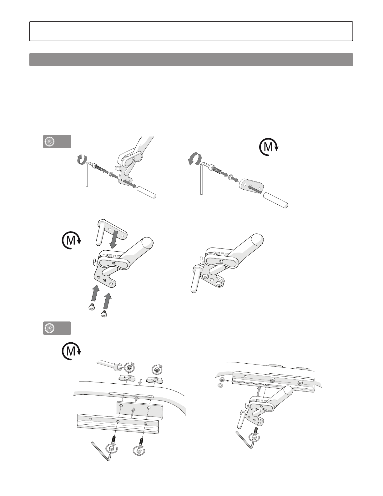
The wheelchair is supplied with push handles/bow handle and head
supports unassembled.
1-3. Install fixed gas piston/actuator.
Ensure that the locking pin is secured
Back support
Page 11

11
Etac / Prio / www.etac.com
Click
back angle
Tilt
Push handle/Bow handle
Install the push handles/bow handle by loosening the handle and
pushing in the locking pins on the push handle. Note! push handle
with symbol for back angle must be installed on the left side, push
handle with symbol for tilt must be installed on the right side.
Fasten the handle.
Make sure knobs are securely tightened.
This is especially important when lifting
the wheelchair with the user in.
Ensure that the push handle locking pins
are secured in the push handle attachment.
5. Installation upon delivery
Head support
Never lift the chair by the head support.
Page 12

12
Etac / Prio / www.etac.com
7 Nm5 mm
Cross brace
5. Installation upon delivery
If the chair is equipped with a push brace, it can sometimes be delivered with the cross brace removed. Fit the cross brace as shown in
the illustrations.
Page 13

13
Etac / Prio / www.etac.com
A
B
6. Charging
When the chair is delivered the battery is base charged. The battery
must be charged fully before the product is used for the first time,
but not later than 12 months after delivery. After this, conservation
charging is required at least once every 12 months.
Charging should be done in a dry environment. Ensure that the charging socket is completely dry before charging.
Insert the charging socket and connect the charger to a wall socket.
The voltage indicator (A) is illuminated, showing that the charger is
connected.
The two indicators showing that the battery is charging (B) flash.
When the lights go out, the battery is fully charged.
When the battery level is low (0-35%) the hand control emits an
audible signal when it is used.
Never charge the battery while the user is sitting
in the chair.
Never charge a damaged battery.
Charging the battery (Electrical recline function)
Page 14

14
Etac / Prio / www.etac.com
14 Nm
17 mm
24 mm
20”, 22”, 24”
16”
1 2a
2b
!
16”
7. Settings
Seat height
Seat height adjustable using:
- The rear wheel position in the gable and
the castor position in the fork.
- Change of rear wheel size
The chassis undercarriage must always be horizontal.
When changing the seat height, the front seat
height must also be adjusted. See Section
"Height adjustment, front".
Bear in mind the risk of tipping.
Always check the positioning of the anti-tips.
Seat height adjustment using the rear wheel position
1. Loosen the nut.
2. Open the kit with the washers and install at the required position
(see table in Section ”Seat height table”).
An adaptor sleeve should be used with 16" wheels in positions A2
and B2.
3. Adjust the castors/castor fork so that the chassis
undercarriage is horizontal (see section
”Height adjustment, front”).
4. Adjust the user brake, see section ”Brake, adjustment”.
Bear in mind the risk of tipping.
Always check the positioning of the anti-tips.
In certain rear wheel positions, there is a crushing
hazard between the arm support and rear wheel (if
the arm support is set at low height).
Page 15

15
Etac / Prio / www.etac.com
± 2,5 cm
5 mm
7. Settings
During installation, make sure that the hubs end up
in the same position on the right and left side.
During installation, check that the rear wheel is
securely mounted. The button in the hub should
pop out to the original position.
See also section ”Seat height table”.
Bear in mind the risk of tipping.
Always check the positioning of the anti-tips.
Seat height adjustment using the rear wheel position
The chassis undercarriage must always be horizontal. When
adjusting the seat height, it is therefore also necessary to adjust
the castor wheel position in the fork or change the castor/fork (see
Section ”Seat height table).
Bear in mind the risk of tipping.
Always check the positioning of the anti-tips.
Height adjustment, front
Height adjustment, front, using the castor wheel position in the fork
Page 16

16
Etac / Prio / www.etac.com
6 mm
20 Nm
7. Settings
5 mm 19 mm
1. Remove the nut cover and disassemble/assemble the front fork with
the castor wheel in accordance with the illustration.
NB! It is important to ensure that the ball bearings and washers in the
attachment (under the retaining nut) are placed in the right order with
the spring washer on top.
During installation, tighten the retaining nut until it comes to a stop
and then release by ½ – 1 turn. The spring washer then has the correct
tension and reduces the risk of the castor starting to "wobble".
Bear in mind the risk of tipping.
Always check the positioning of the anti-tips.
19 mm
Disassembly/assembly of the front fork
With a 6.5" castor wheel, the front fork mounting must be heightadjusted in certain rear wheel positions. Loosen the screw that holds
the front fork mounting and adjust the height so that the lower tube
of the chassis is parallel to the floor.
Tighten the screw again.
Bear in mind the risk of tipping.
Always check the positioning of the anti-tips.
Height adjustment, front, by replacing the front fork/castor wheel
See section “Height adjustment, front, using the castor wheel position in
the front” and ”Seat height table”.
Bear in mind the risk of tipping.
Always check the positioning of the anti-tips.
Forward height adjustment using front fork attachment
Page 17
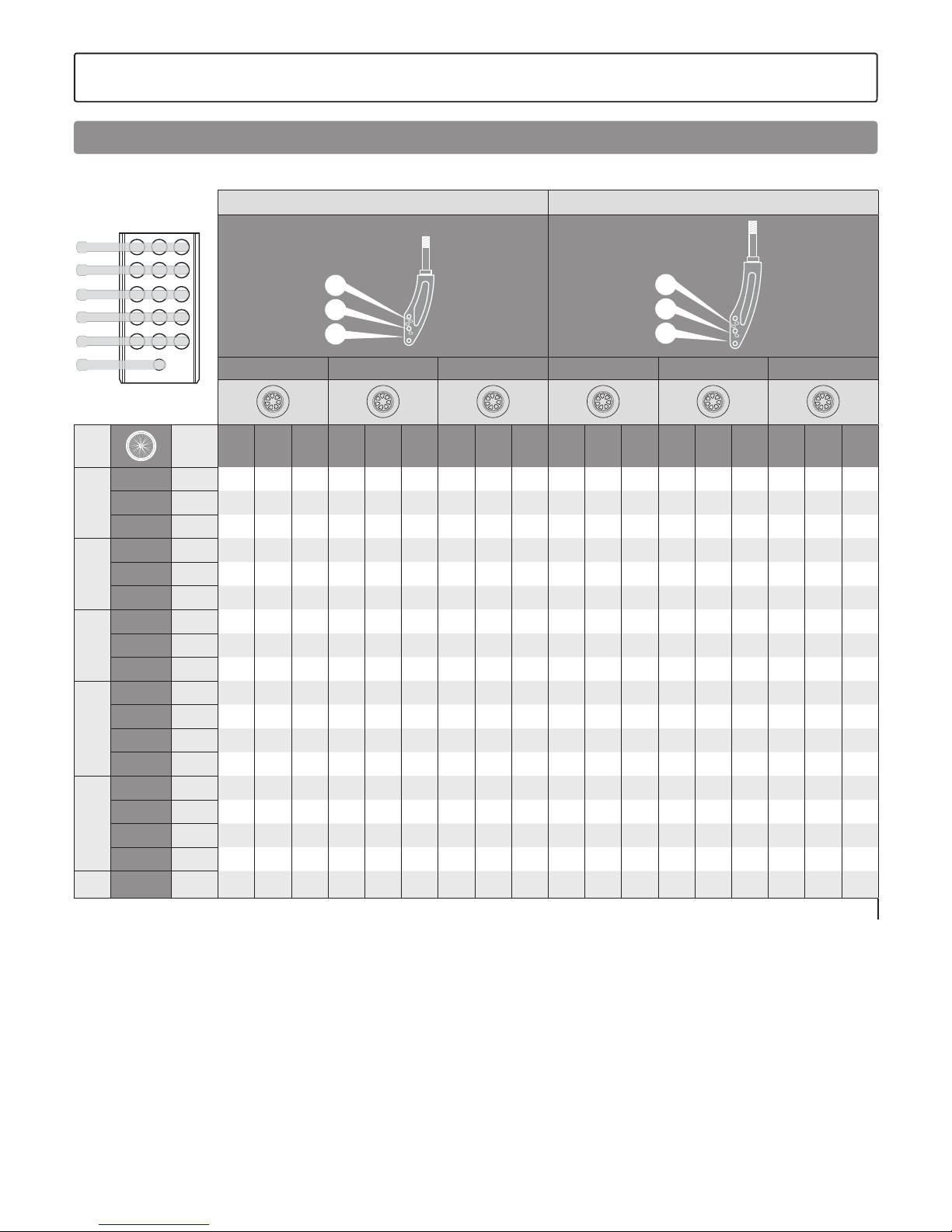
17
Etac / Prio / www.etac.com
1 2 3
E
D
C
B
A
a
7. Settings
Short Fork Medium Fork
S1
S2
S3
M1
M2
M3
S1 S2 S3 M1 M2 M3
Pos.
Seat
height
6” 6.5" 8” 6” 6.5" 8” 6” 6.5" 8” 6” 6.5" 8” 6” 6.5" 8” 6” 6.5" 8”
E
20" 38.0
X
22" 40.5
X X X X
24" 42.5
X** X X X** X* X
D
20" 40.5
X X
22" 43.0
X X X X* X X
24" 45.0
X** X** X X** X** X X
C
20" 43.0
X X X X* X X
22" 45.5
X X X X
24" 47.5
X** X X** X X X** X
B
20" 45.5
X X X X
22" 48.0
X X X
24" 50.0
X X X X**
16"*** 40.0
X X
A
20" 48.0
X X X
22" 50.5
X X X
24" 52.5
X
16"*** 42.5
X X X* X
a
16"*** 45.0
X X X
*Only 8 x 13/8” (200 x 35 mm), not 8 x 2” (200 x 50 mm)
** The height of the front fork mounting must be adjusted. See section 'Height adjustment using front fork mounting'.
*** Chair equipped with electrical recline function must have anti-crush guard fitted.
Seat height table
Page 18
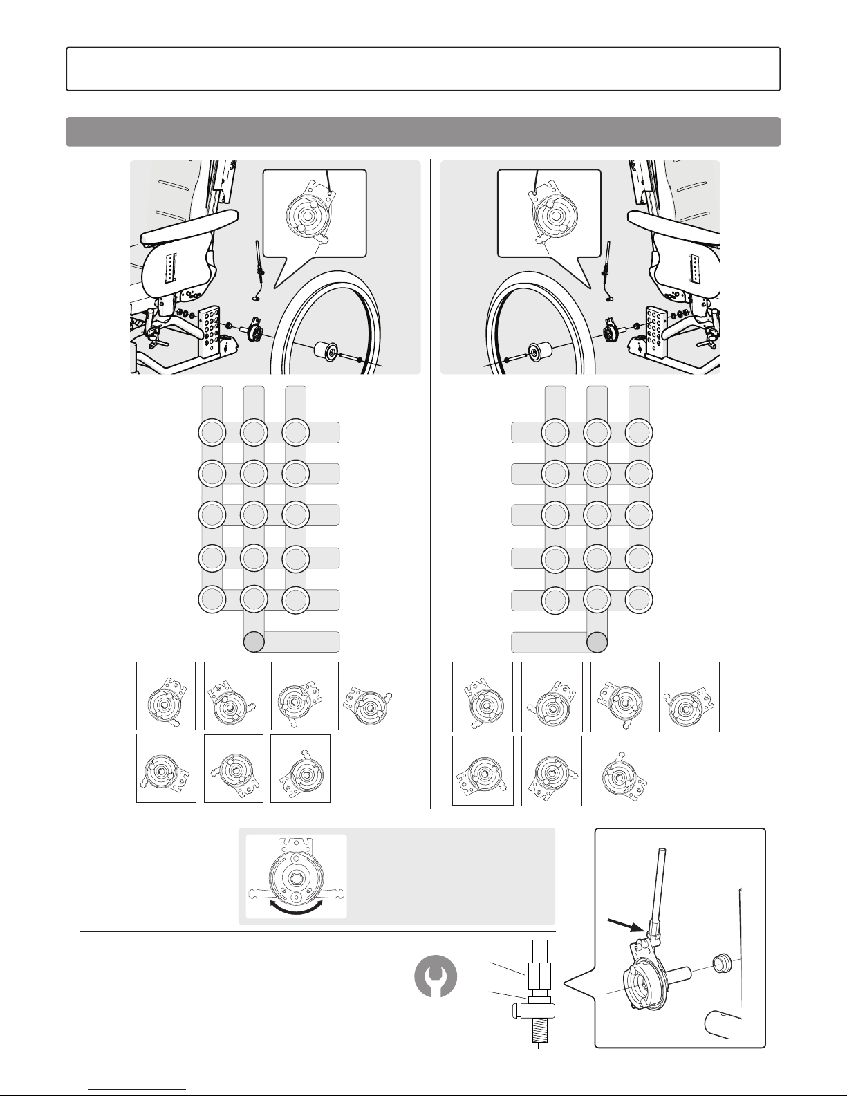
18
Etac / Prio / www.etac.com
B
A
Pos A2, A3,
B2, B3, C2, C3
Pos D3Pos D1
Pos E1 Pos E3Pos D2, E2
Pos a2, A1, B1, C1
Pos A2, A3,
B2, B3, C2, C3
Pos D3Pos D1
Pos E1 Pos E3Pos D2, E2
Pos a2, A1, B1, C1
E
D
C
B
A
a
a
1 2 3
E1 E2 E3
D1 D2
B2
D3
C1
B1
A1
C2
A2
a2
C3
A3
B3
E
D
C
B
E
D
C
B
A
3 2 1
E1
D1
C1
B1
A1
E2E3
D2
B2
D3
C2
A2
a2
C3
A3
B3
a
E
D
C
B
E
D
C
B
A
3 2 1
E1
D1
C1
B1
A1
E2E3
D2
B2
D3
C2
A2
a2
C3
A3
B3
When adjusting the brake loosen nut (A) and adjust
the brake by moving (B) up/down.
When the brake has a reasonable effect tighten nut (A).
This adjustment should be carried out when the brake
is not functioning satisfactorily.
8 mm
The brake arm
can be turned.
7. Settings
Seat height adjustment using the attendant brake
Page 19
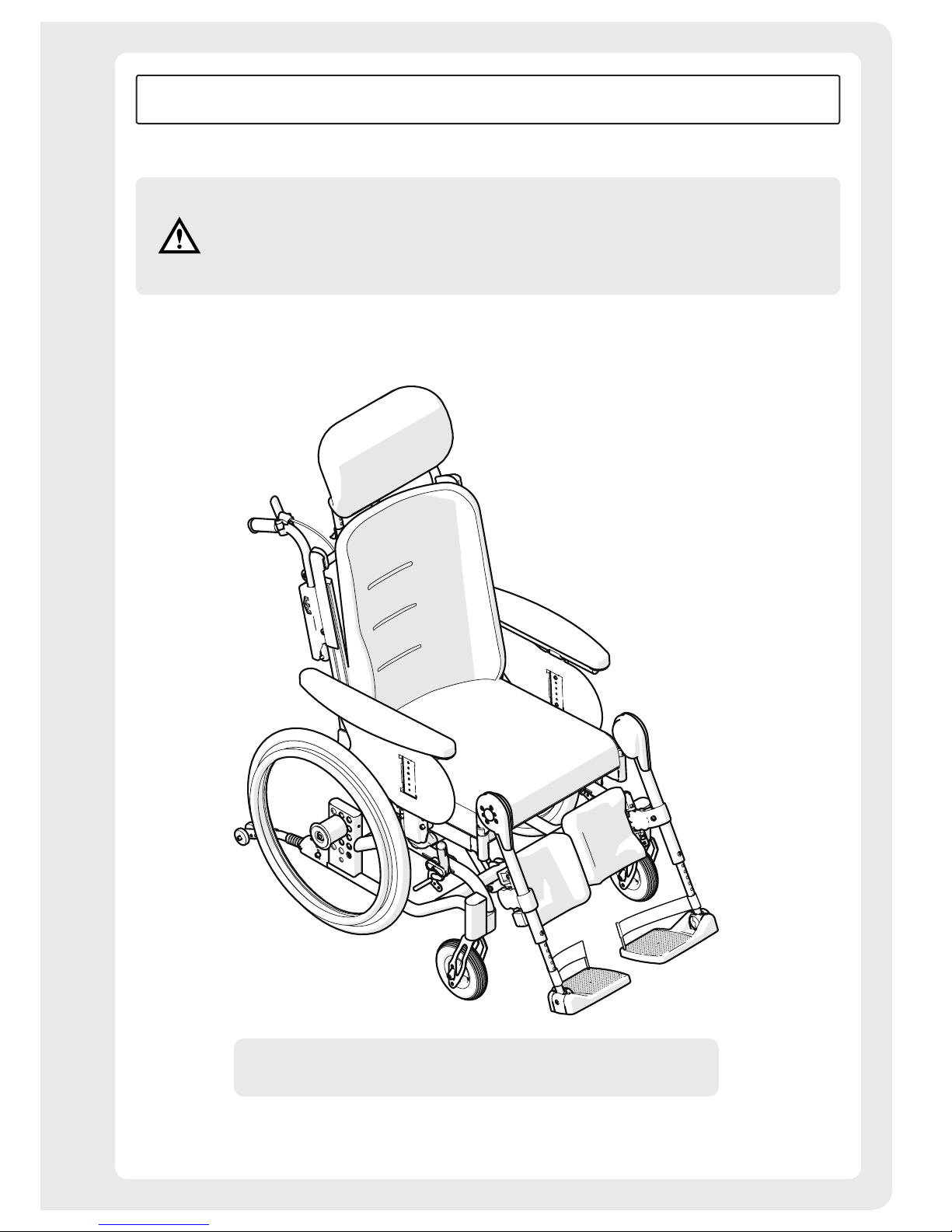
19
Etac / Prio / www.etac.com
Etac Prio
75341F 2018-10-18
This part of the manual (User Manual) must be removed
and always be supplied with the wheelchair as it contains
important user information.
User manual
Page 20
20
Etac / Prio / www.etac.com
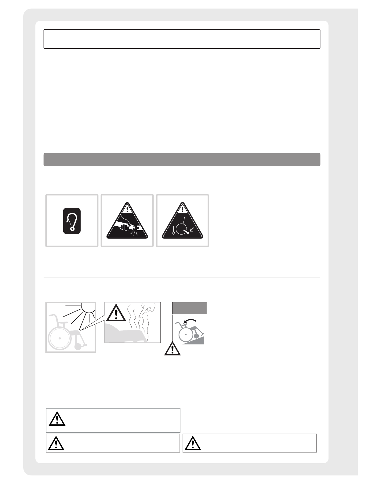
These symbols occur on labels and in the user manual
and must be taken into consideration during use.
Securing Do not lift the chair by
removable parts
Risk of tipping: Always
keep the anti-tips
folded down.
Bear in mind the risk of tipping.
Always check the positioning of the anti-tips.
Bear in mind the risk of tipping.
Always use the anti-tips!
General warnings
The following must be taken into account when using the product.
Max. incline
(excluding anti-tips)
6°
Bright sunlight could
heat parts of the chair
and cause burns
The chair might tip
if the incline at the rear
is greater than 6°.
Use anti-tips!
Symbols and warnings
User manual
Contents
User manual
Symbols and warnings ......................................................18
Seat comfort settings .................................................. 19-21
Handling ..................................................................... 22-26
Driving technique, use ................................................ 27-29
Transport in vehicles ..........................................................30
Removal of upholstery .....................................................31
Maintenance & Troubleshooting form ...............................32
After adjusting the seat height, centre of balance
or back support angle, always ensure that you check
the function of the anti-tips.
Page 21
21
Etac / Prio / www.etac.com
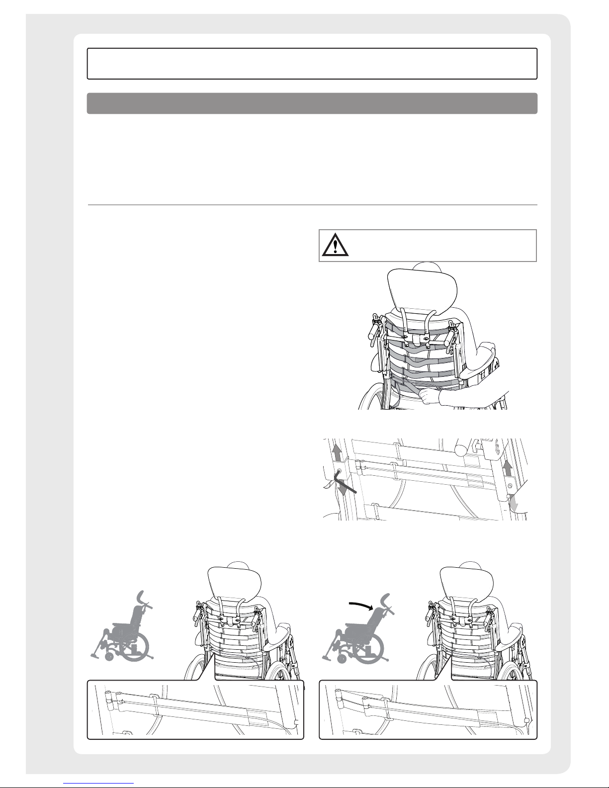
Back support upholstery
The back support upholstery is adjusted with the user sitting
in the wheelchair.
• Make sure the user is sitting as far back in the seat
as possible.
• Angle the back support so that the dynamic pelvic support
is activated (see illustration).
• Support the pelvis by tightening the dynamic pelvic
support belt. Remember that the belt is automatically
loosened when the back support is tilted back (see
illustration). With the Comfort back support cover, the
back support belt is
also height-adjustable.
• Then adjust the upper strap to provide the user with
upper body support and balance.
• The other straps are adjusted to provide space for the
user’s posterior and follow the back’s natural curvature.
Bear in mind the risk of tipping.
Always check the positioning of the anti-tips.
Seating comfort
Good seating comfort depends on the needs and
possibilities available to each individual. The following
general guidelines here show what to consider when
settings are made.
Dynamic pelvic support activated Dynamic pelvic support deactivated
Seating comfort settings
User manual
Page 22
22
Etac / Prio / www.etac.com
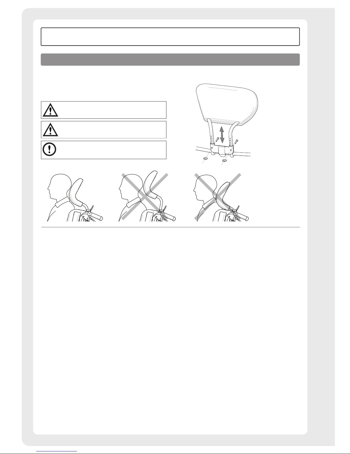
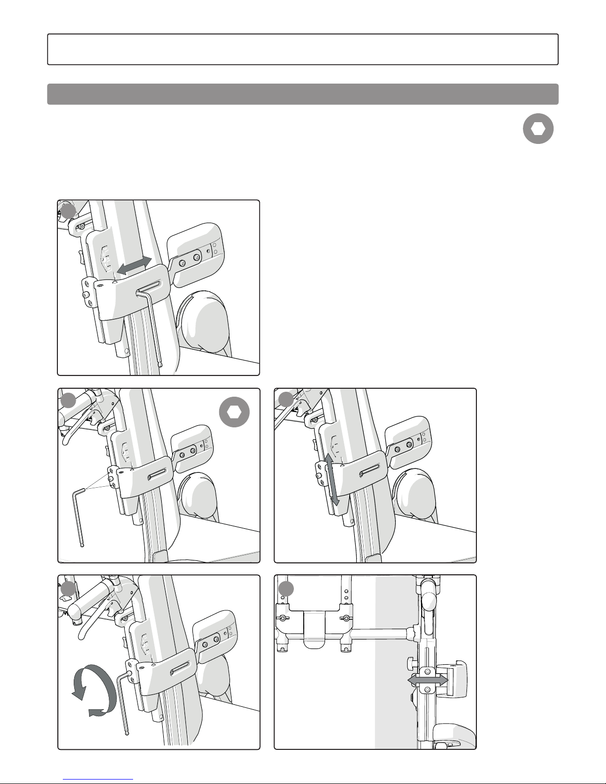
Head support - height
The head support height is adjusted by loosening the screws
and nuts.
Bear in mind the risk of tipping.
Always check the positioning of the anti-tips.
Never lift the chair by the head support.
It is easier to install screws and nuts when
the head support is removed.
Seating comfort settings
User manual
Page 23
23
Etac / Prio / www.etac.com
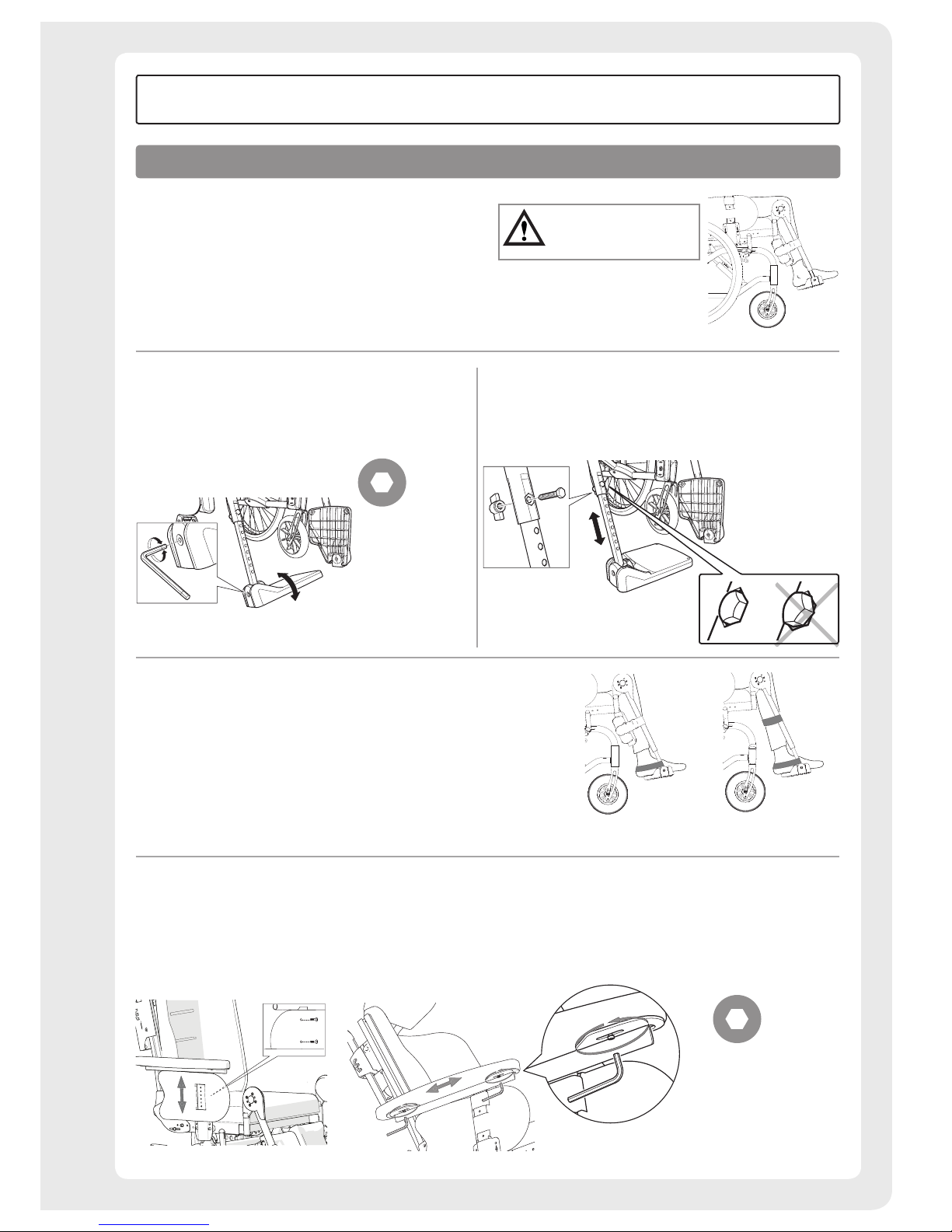
Footplates
Adjust the height to support the feet and so that
the thighs rest against the seat cushion.
For outdoor use the footplates should be raised
4 – 5 cm above the ground.
Tipping risk!
Never stand on
the footplates
Angle adjustment
Adjust the angle of the foot supports so that your ankles
are at a 90° angle.
Adjusting the height
Fully loosen the locking handle on the leg support. Remove
the screw. Set the height. Replace the screw and handle.
Tighten securely.
Arm support (adjustment)
• Loosen the screws on the inside of the supportive plate.
• Move the arm support up or down to the desired height
and tighten the screws.
• Loosen the screws on the underside of the arm support
cushion to adjust the length of the cushion.
• Correctly adjusted arm supports provide upper body
support. The arm support plate should be approximately 5
mm taller than the elbow when bent at an angle of 90°.
5 mm
3 mm
Calf/heel strap
• Adjust the length so that the centre of the feet are placed
on the footplates.
Seating comfort settings
User manual
Page 24
24
Etac / Prio / www.etac.com
Click!
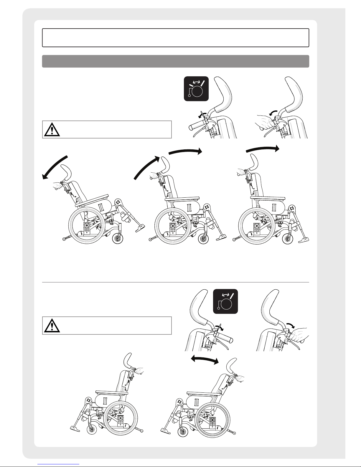
Tilt function, comfort lock
The chair is tilted by pressing down the adjustment on the
right handle frame. On chairs equipped with comfort locks,
forward tilting is stopped at the pre-installed comfort lock.
Keep the adjustment pressed down, and press forward
slightly to get past the comfort lock.
Bear in mind the risk of tipping.
Always check the positioning of the anti-tips.
Back angling
The back angle is changed by pressing down the back angle
controls on the left side.
Bear in mind the risk of tipping.
Always check the positioning of the anti-tips.
How to use
User manual
Page 25
25
Etac / Prio / www.etac.com
How to use
User manual
Electrical recline function
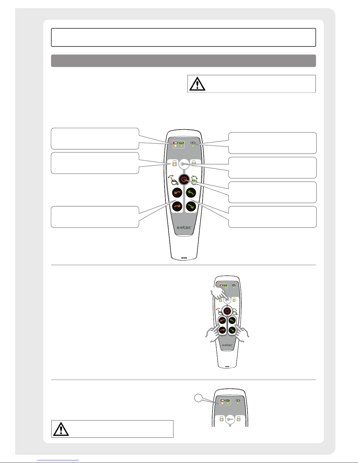
Back angle and seat angle are adjusted by means of the
hand control. The hand control is deactivated after not being
used for 30 seconds. It can also be deactivated manually by
clicking the on/off button.
The hand control must not be handled by children or
by cognitively impaired persons.
Charging
When the battery level is low (0-35%) the hand control
emits an audible signal when it is used and the yellow light
(A) is lit. See section 'Charging'.
Never charge the battery while the user is sitting
in the chair.
Voltage indicator Shows green light
when charger is connected to wall
socket
Lock function
On/off
Seat recline (green)
Back recline (orange)
Indicator lights for lock function
Battery indicator Green light = battery level 100-40% Yellow light =
40-0%
A
Locking of functions
The back and/or seat recline functions can be locked. Press
the locking button and hold it down. At the same time,
press one of the arrow buttons for the selected function.
(Both of them work.) The indicator light is lit when the
selected function is locked.
Repeat the same procedure to unlock.
Page 26
26
Etac / Prio / www.etac.com
How to use
User manual
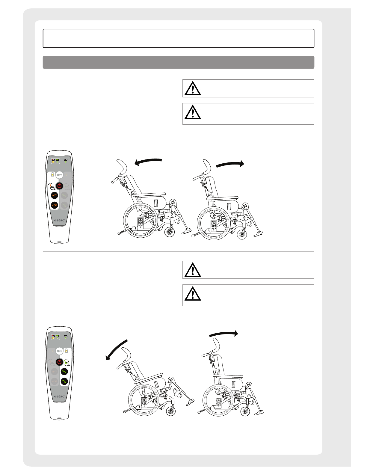
Electrical recline function, back angle
The back angle is adjusted by means of the arrow buttons
on the left-hand side of the hand control.
Bear in mind the risk of tipping.
Always check the positioning of the anti-tips.
The electrical recline function must not be used when
there is an obstacle, e.g. when the user has their legs
under a table.
Electrical recline function, seat angle
The seat angle is adjusted by means of the arrow buttons on
the right-hand side of the hand control.
Bear in mind the risk of tipping.
Always check the positioning of the anti-tips.
The electrical recline function must not be used when
there is an obstacle, e.g. when the user has their legs
under a table.
Page 27
27
Etac / Prio / www.etac.com
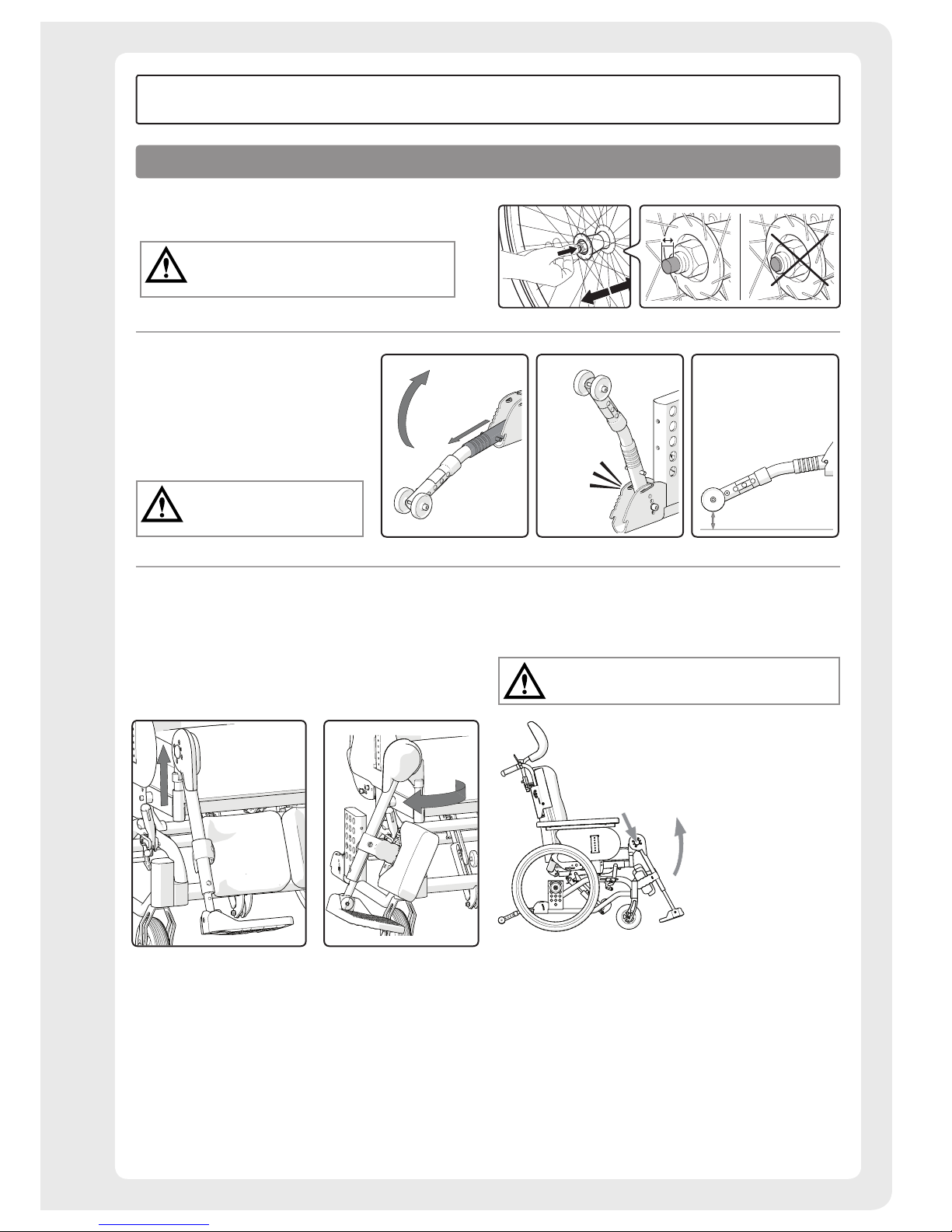
30-70 mm
Rear wheel with quick release hub
During installation, check that the rear wheel is
securely mounted. The button in the hub should
pop out to the original position.
Anti-tips
• The anti-tips can be folded and are
height-settable.
• When you fold the anti-tips out of
the way, ensure that the locking pins
are properly engaged.
Bear in mind the risk of tipping.
Always check the positioning of
the anti-tips.
Leg support, elevating
The leg support can be lifted/swung to the side as needed.
The footplates can be folded and the calf support can
be swung to the side.
Leg support angle
The leg support angle is adjustable in fixed positions. Set
the angle by pressing down the button and lifting/lowering.
Don’t lift the chair by the leg supports.
How to use
User manual
Page 28
28
Etac / Prio / www.etac.com
A
A
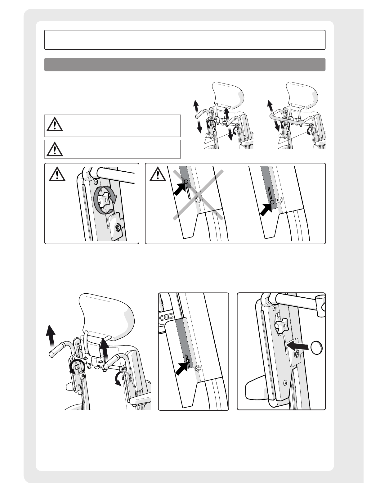
The push handle/bow handle, height-adjustable
Loosen the knob for the push handle lock (A). Install desired
height. Ensure that the push handle is in
a "snap lock" position, tighten the knob.
Make sure knobs are securely tightened.
This is especially important if the chair is
to be lifted with the user sitting in it.
Ensure that the push handle locking pin is always
secured under the push handle attachment.
Loosen - Push handle/bow handle
Loosen the knob for the push handle lock. Pull up the push handle until the locking pin engages in the track.
Insert a coin or a flat tool in the groove on the right side to unsnap the locking pin on the handle. Pull the push/pull
handle out of the attachment.
How to use
User manual
Page 29
29
Etac / Prio / www.etac.com
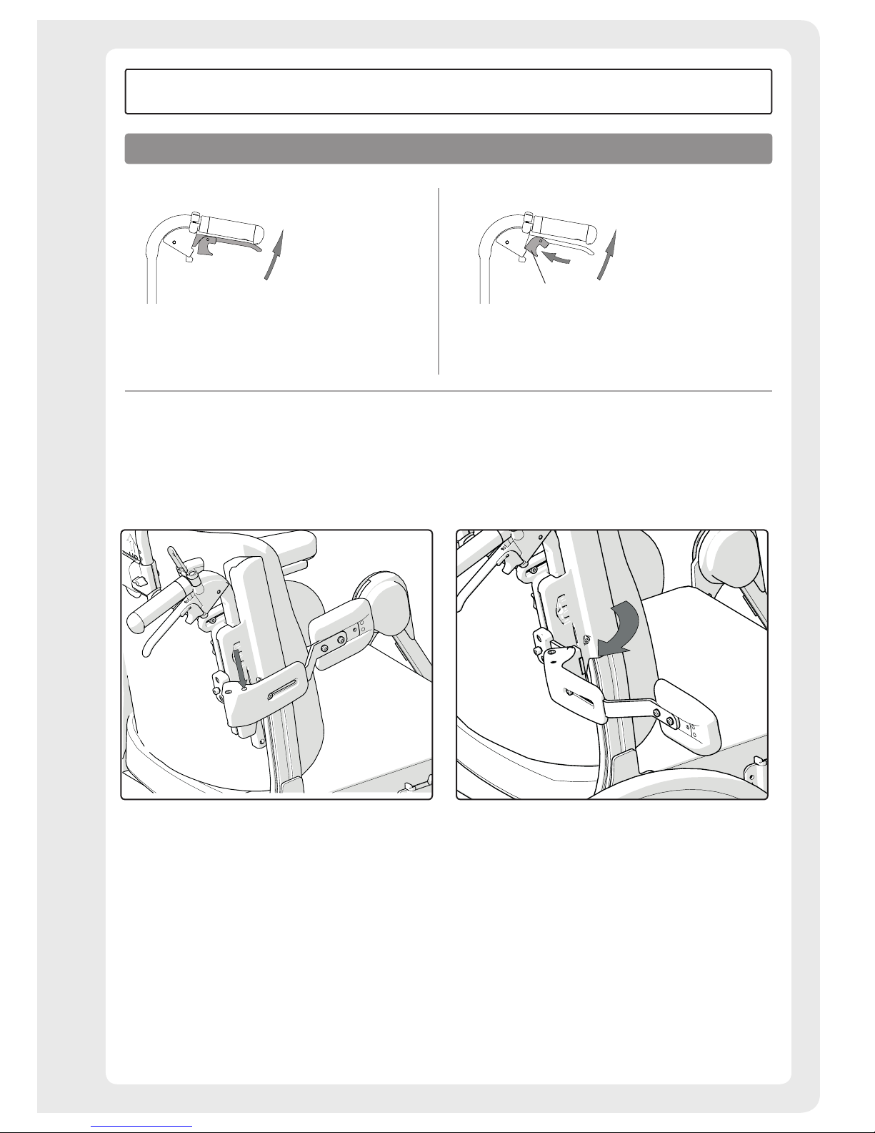
Attendant brake (motion brake)
• Brake while in motion by pushing the brake handle
upwards.
Attendant brake (parking brake)
A
• Activate the parking brake by pressing the brake handle
upwards and pressing button A.
• Loosen by pressing the handle upwards.
How to use
User manual
Trunk support - swing-away
The trunk support is swung to the side by pressing the
button. The arm support can be lifted off when the trunk
support has been swung to the side.
Page 30
30
Etac / Prio / www.etac.com
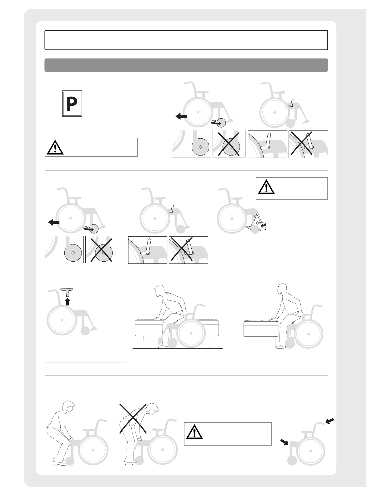
Parking
Transferring to/from the wheelchair
Sideways
Remove the arm support on the
side on which transfer will take
place.
From the front
Lifting the wheelchair
• Ensure that the vertically adjustable push handles
are properly tightened.
• Swing the leg supports away and lift the wheelchair
by the front upper part of the frame.
Never lift the chair by
the head support, leg supports
or arm supports.
Never stand on the
footplates as there
is a risk of tipping!
Do not park the wheelchair on
a hill when it has a user in it.
Driving technique, use
User manual
Page 31
31
Etac / Prio / www.etac.com
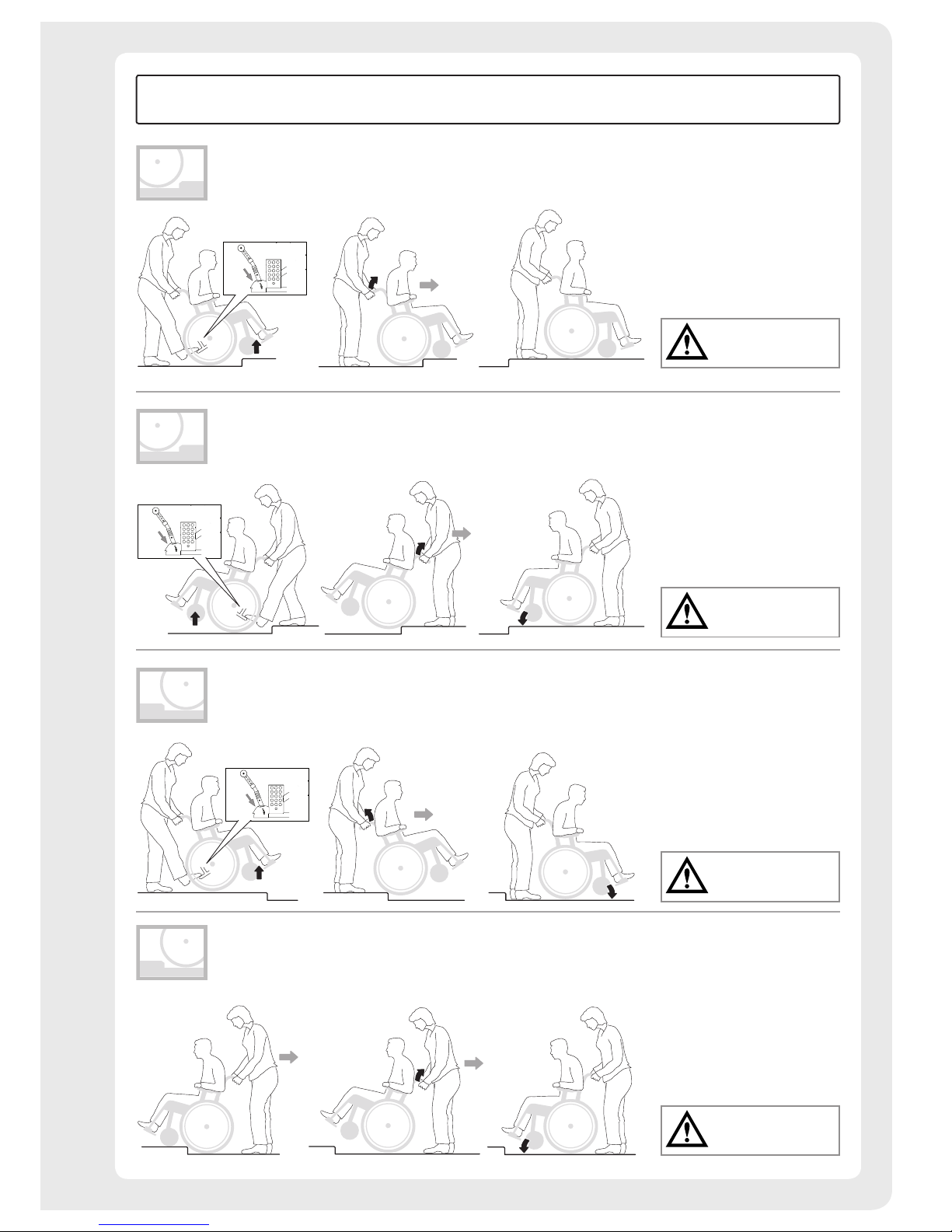
Enable the anti-tips
afterwards.
Enable the anti-tips
afterwards.
Enable the anti-tips
afterwards.
Enable the anti-tips
afterwards.
Carers, up forwards
– Ensure that the anti-tips are disabled.
Carers, up backwards
– Ensure that the anti-tips are disabled.
Carers, down forwards
– Ensure that the anti-tips are disabled.
Carers, down backwards
– Ensure that the anti-tips are disabled.
User manual
Page 32
32
Etac / Prio / www.etac.com
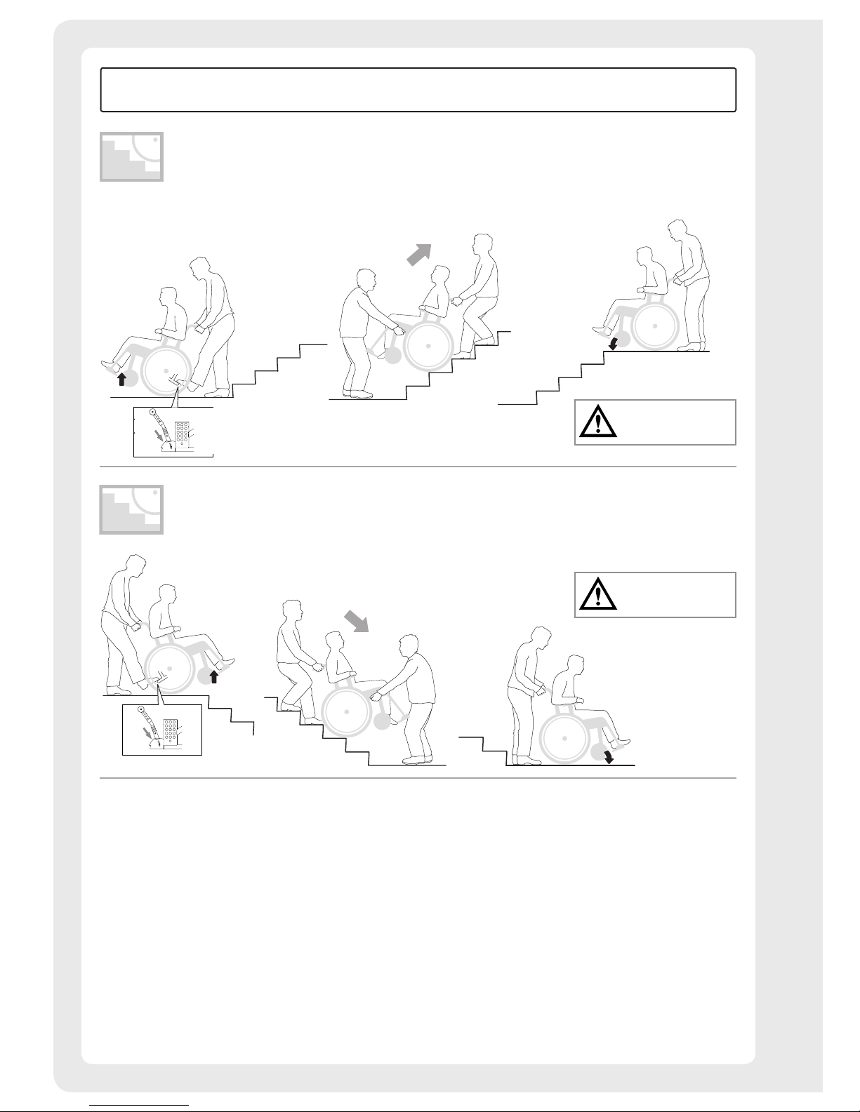
Enable the anti-tips
afterwards.
Enable the anti-tips
afterwards.
Stairs, down
– Ensure that the anti-tips are disabled and that
height-adjustable handles are securely tightened.
We recommend there always being two carers for
this transfer. One walking behind and holding the
push handle and one walking in front, holding the
frame. Never use an escalator, even if a carer
is available.
Stairs, up
– Ensure that the anti-tips are disabled and that
height-adjustable handles are securely tightened.
We recommend there always being two carers for
this transfer. One walking behind and holding the
push handle and one walking in front, holding the
frame. Never use an escalator, even if a carer
is available.
User manual
Page 33
33
Etac / Prio / www.etac.com
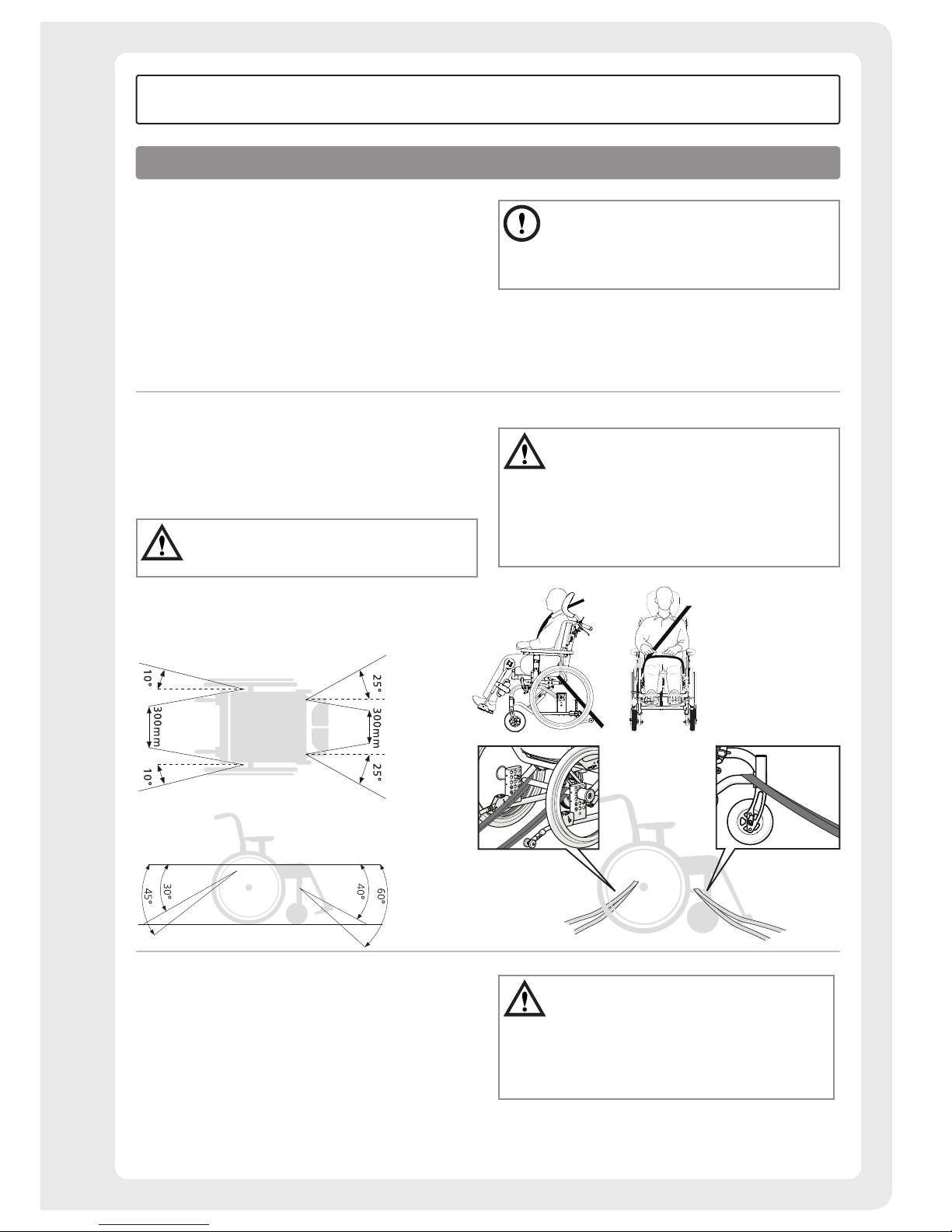
Etac's wheelchairs are crash-tested and approved according
to ISO 7176-19 (see Section ”Tests and warranties” in
the manual).
Etac recommends in the following order:
1) The user transfers to a seat in the vehicle and uses the
vehicle’s 3-point belt while travelling. The wheelchair
is then placed in the boot or safely in the back seat so
that it cannot overturn or roll.
• The wheelchair should preferably be placed in
the car boot.
• If the wheelchair is placed on the back seat,
ensure that it cannot overturn or roll. If possible
secure the wheelchair with the car’s safety belt.
2) The wheelchair is secured facing forwards in the vehicle
as per the below, the user uses a separate 3-point belt
that is secured in the vehicle. This is the way in which the
wheelchair is tested and approved according to
ISO 7176-19.
Securing
• The restraining device must not be passed
through the wheels or around the back tubes.
• The parking brake should be used.
• The anti-tips must be activated.
• Accessories that can be removed without tools must
be removed and secured.
• A correctly configured Etac head support must be
used (see Section ”Seat comfort settings”).
• Handrims must be installed on the rear wheels (not
16” wheels).
3) According to Directive 2001/85/EC, appendix VII, point
3.8.3, there may be specially marked wheelchair locations
in vehicles that permit transport with a wheelchair facing
in the direction of travel. If this means of travel is used,
the user/carer must be aware while travelling, prepared
for sudden movements and have the capacity to maintain
a safe sitting position throughout the entire journey. The
user’s disabilities must not be of such an extent that he/
she is not able to hold onto the handles fitted in the
vehicle when there are changes of speed or direction.
• The parking brake should be used.
• The anti-tips must be activated.
• Accessories that can be removed without tools
must be removed and secured.
• A correctly configured Etac head support must be
used (see Section "Seat comfort settings").
• A positioning belt should be used.
Transportation in vehicles
User manual
Page 34
34
Etac / Prio / www.etac.com
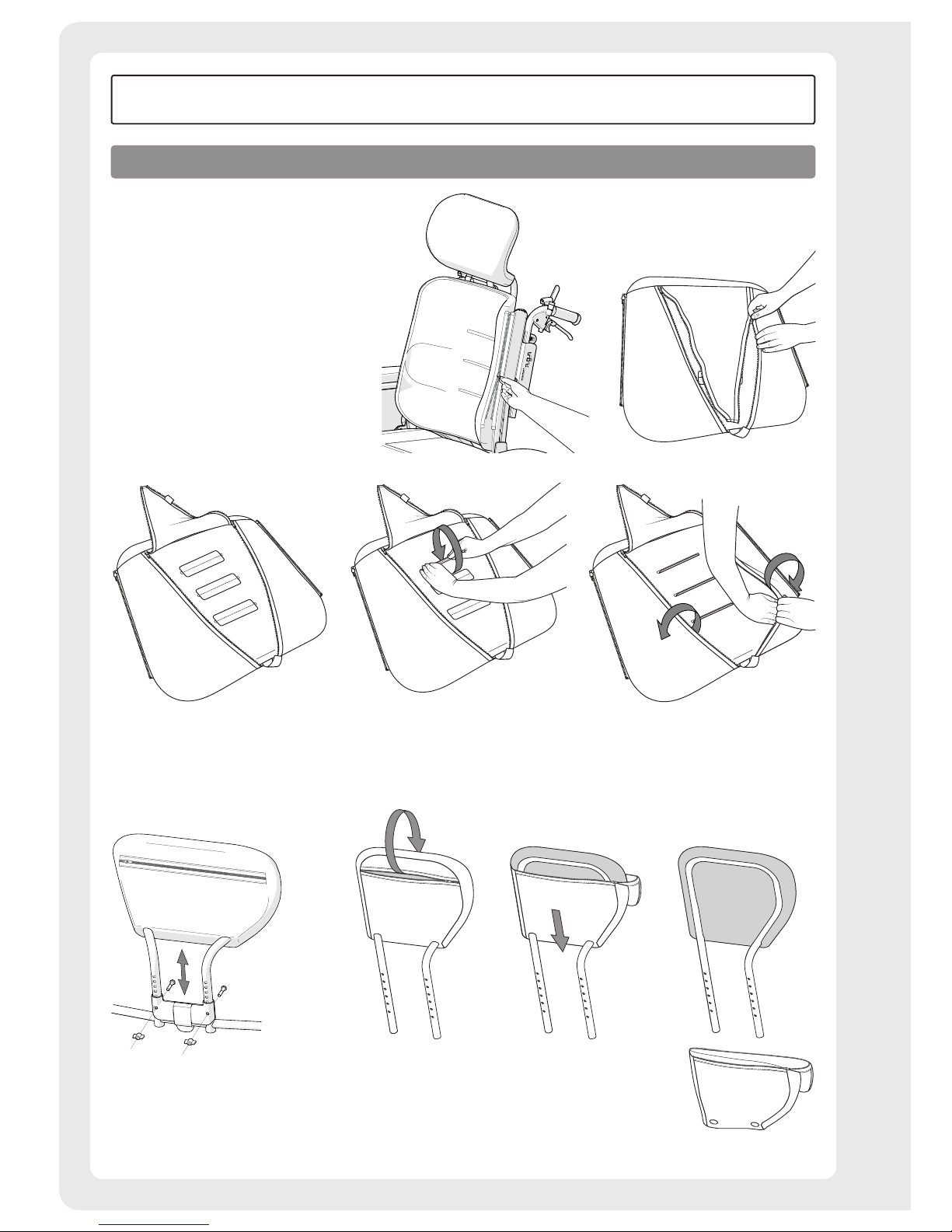
Back cushion
• The back cushion is removed
and attached using the zipper.
Removal of covers
User manual
Page 35
35
Etac / Prio / www.etac.com
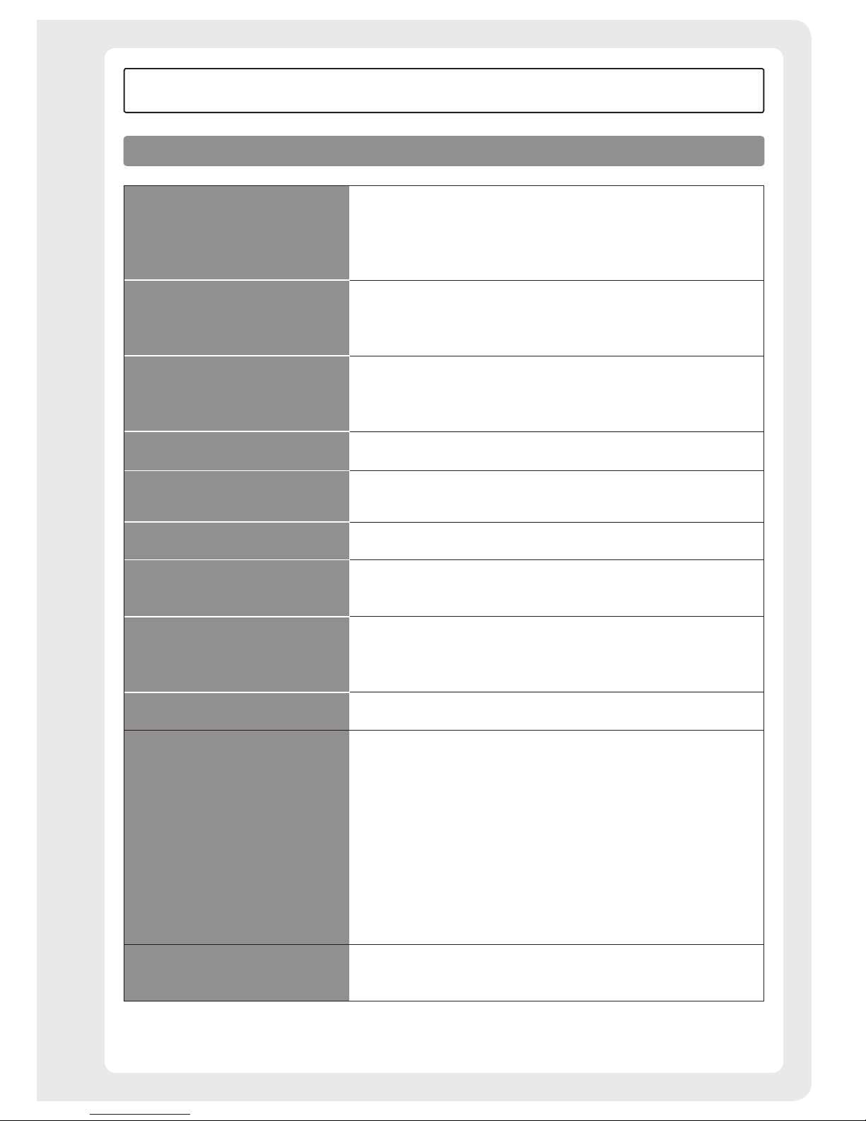
Fault-finding chart
User manual
The wheelchair pulls to the side
• Check that the front fork attachments are mounted correctly
• Check that the rear wheels are mounted correctly
• The user is distributing weight unevenly in the wheelchair
• More strength being used on one side than the other
The wheelchair is ”heavy”
to operate
• Check that the rear wheels are mounted correctly
• Clean the castor axles of hair and dirt
• Too much weight over the castors. Adjust the centre of balance
The wheelchair is ”heavy”
to turn
• Check that the front forks have not been tightened too much
• Clean the castor axles of hair and dirt
• Too much weight over the castors. Adjust the centre of balance
The user brake is not effective
• Adjust the distance between the tyre and the brake
(see Section ”Brake, adjustment”)
The attendant brake is not effective
• Adjust the wire length using the adjustment nipple on the brake drum
(see Section ”Attendant brake”)
Rear wheels are ”loose” • Adjust the length of the axle shaft
Rear wheels hard to
remove/replace
• Clean and lubricate the quick release using e.g. cycle oil
• Adjust the length of the axle shaft
The castor wheels ”wobble”
• The front forks have not been tightened sufficiently
• Check that the front fork attachments are mounted correctly
• Too much weight over the castors. Adjust the centre of balance
The wheelchair feels "awkward" • Check that screws and controls are properly tightened
Electrical back and seat recline
function does not work
• Hand control has been deactivated – activate by pressing the on/off button
• End position has been reached – use opposite button
• Battery is not charged – charge battery
• Hand control function is locked – unlock function (See section 'Electrical
recline function')
• Hand control is not connected – check that the hand control is correctly
connected to the electronics unit
• Error on hand control – phone retailer or technician for replacement of
hand control
• Error on electronic unit – phone retailer or technician for replacement of
electronics unit
• Damaged cables – phone retailer or technician for replacement of cables
Electrical back and seat recline
function does not work in spite
of action taken
• Reset the system by pressing the arrow up buttons and holding for five
seconds
Page 36
36
Etac / Prio / www.etac.com
Rear Wheels: Clean the quick release axles when necessary.
Castor wheel: Clean the castor wheel axles when necessary.
Chassis:
Clean the frame with a non-abrasive cleaning
agent with a pH level between 5 and 9, or with
a 70% disinfectant solution. Rinse and dry.
Upholstery: Wash, see label on upholstery.
Seat and back cushion: Remove the cover and wash in
accordance with the washing instructions on the label.
For more severe problems, contact the Technical Aids Centre.
When necessary lubricate moving parts/joints
with bicycle oil or similar.
Care and maintenance
Etac
Box 203, 334 24 Anderstorp, Sweden
Tel +46 371 58 73 00
Fax +46 371 58 73 90
www.etac.com
User manual
Lithium batteries are subject to statutory regulations.
Always contact your travel organiser or freight company
for information about applicable freight regulations before
transportation.
Transportation in aeroplanes
Page 37
37
Etac / Prio / www.etac.com
1
3
2
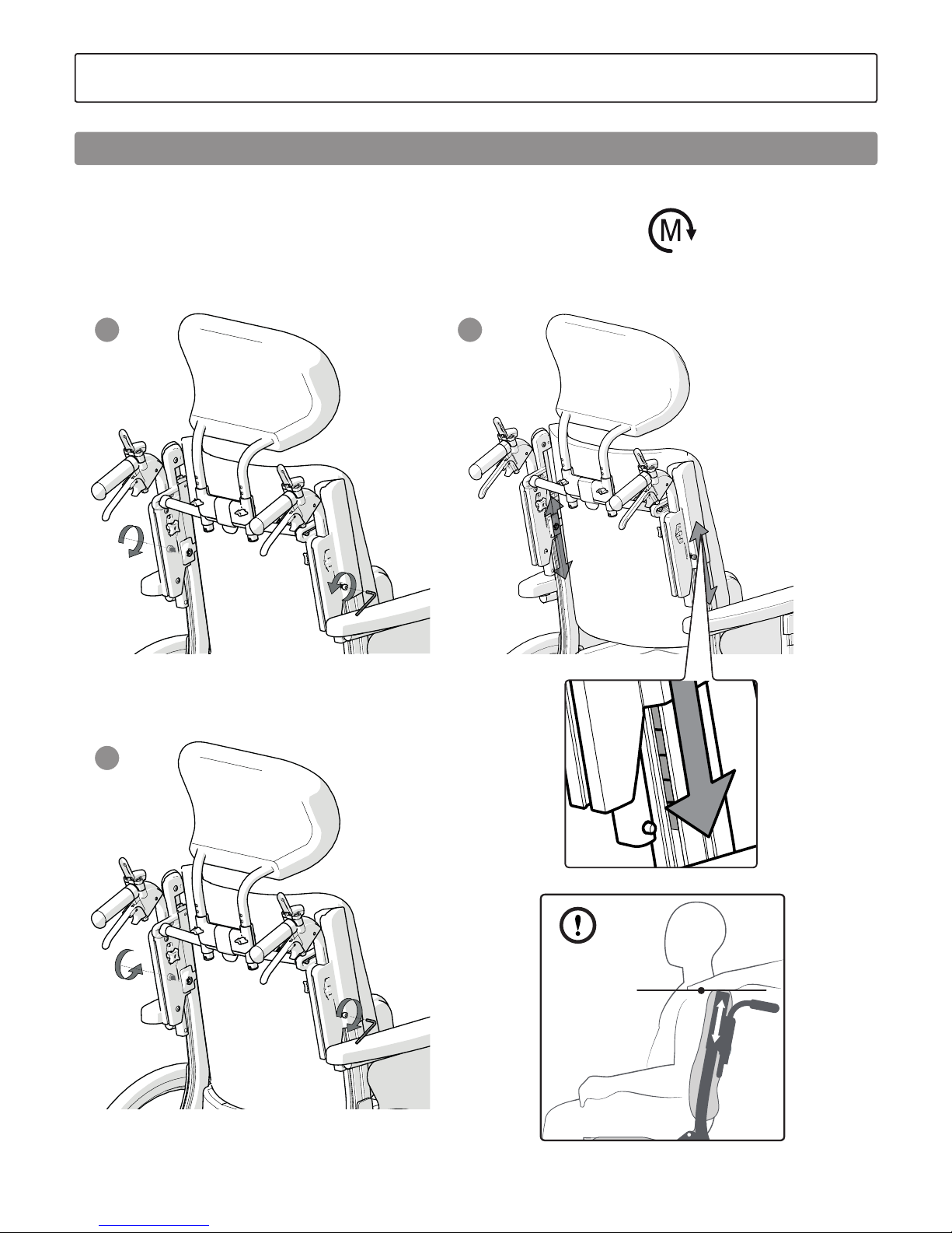
The height of the back can be adjusted:
1. Loosen the screws on the side of the back support.
2. Gradually raise or lower using the scale. Ensure
that both sides have the same height setting.
We recommend that the top of the back support
tubes is aligned with the axles.
3. Tighten the screws securely.
7. Settings
Back height adjustment
12 Nm
Page 38
38
Etac / Prio / www.etac.com
1
2 3
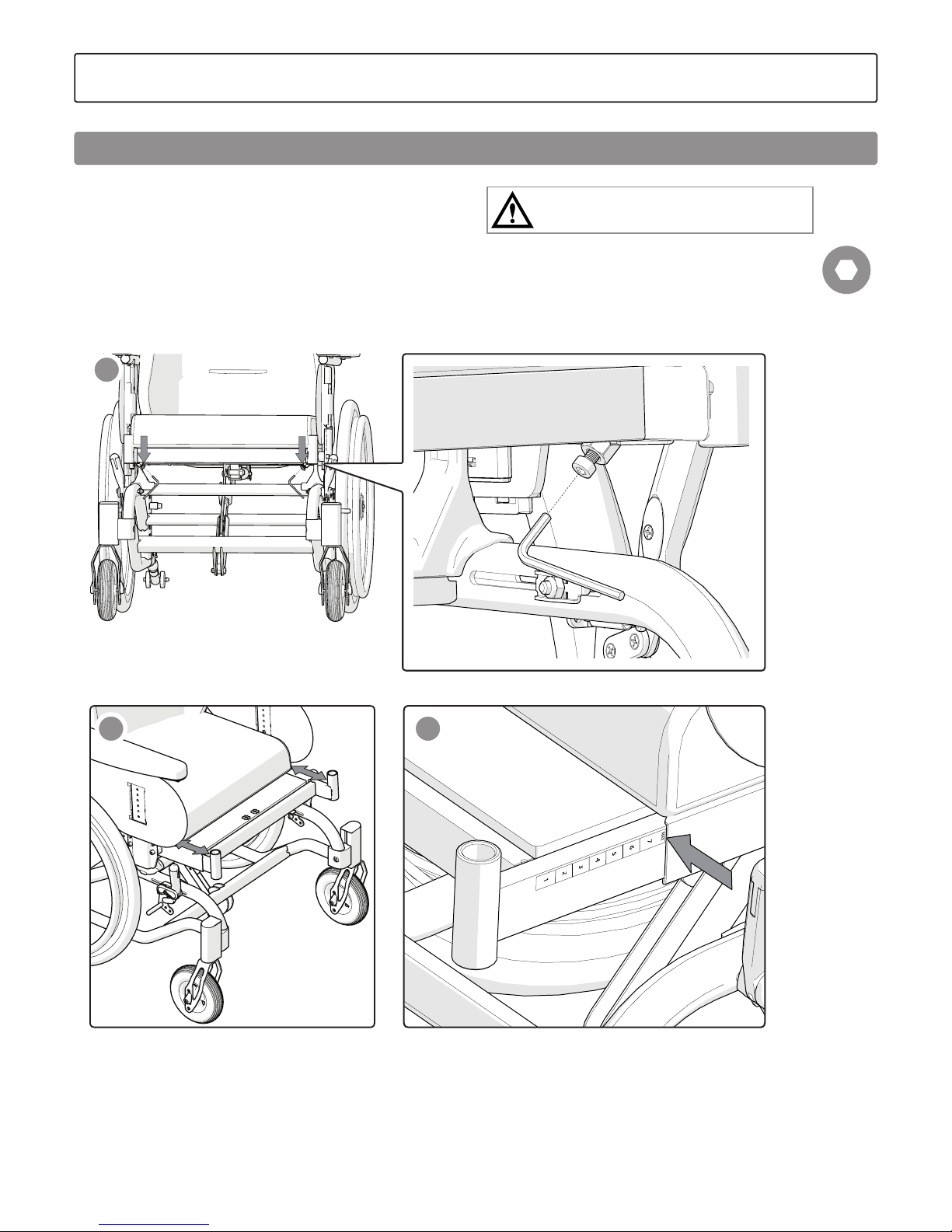
1. Loosen the screws on both sides of the seat.
2. Adjust the seat depth by pulling the seat out or
by pushing it in.
3. The front seat depth can be adjusted by up to 7 cm.
Do not pull the seat out further than the "max. line".
4. Tighten the retaining screws
Bear in mind the risk of tipping.
Always check the positioning of the anti-tips.
5 mm
7. Settings
Seat depth, front
Page 39
39
Etac / Prio / www.etac.com
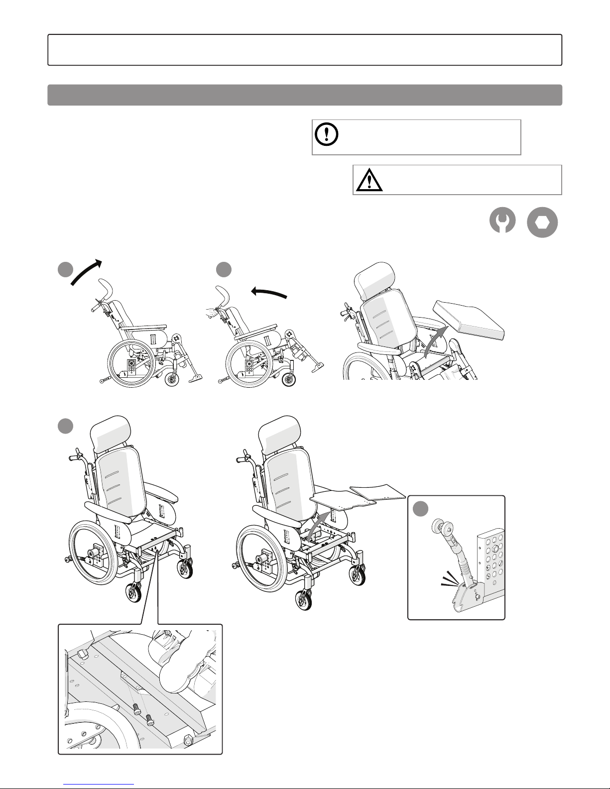
“Click”
1 2
3
4
The seat depth can be adjusted in three fixed positions by repositioning the back chassis and the rear seat plate.
1. Tilt the back support upwards.
2. Tilt the seat as far back as possible and remove
the seat cushion.
3. Lift the seat plates off by loosening the screws
on the bottom of the seat chassis.
4. Twist the anti-tips to one side.
Remember that the wheel positions might also
need to be re-adjusted to achieve correct balance
in the chair.
Bear in mind the risk of tipping.
Always check the positioning of the anti-tips.
13 mm 5 mm
7. Settings
Seat depth, rear
Page 40
40
Etac / Prio / www.etac.com
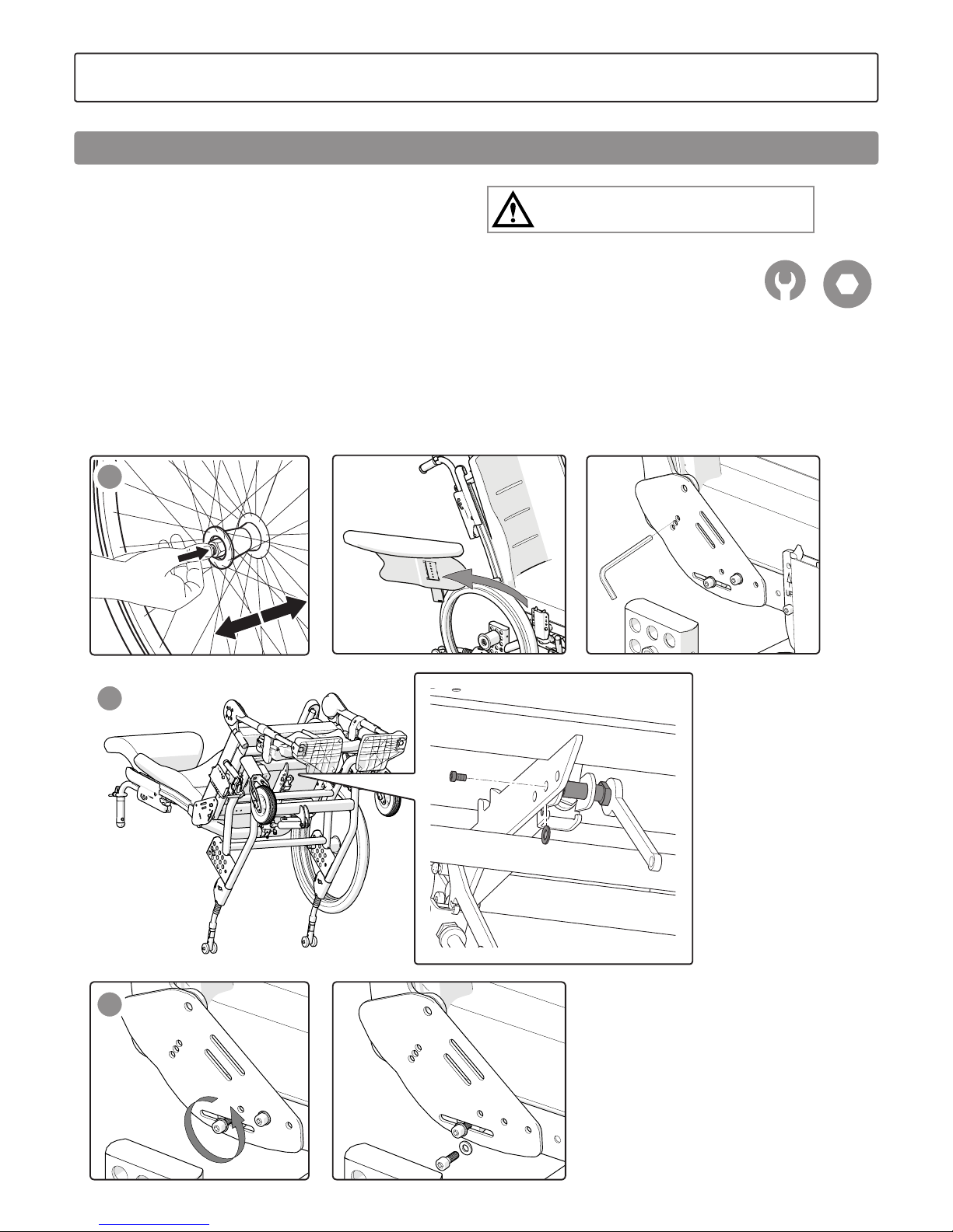
5
6
7
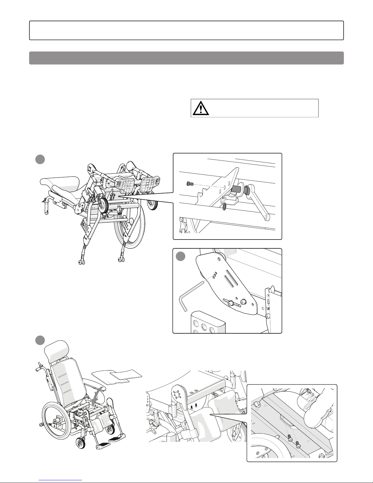
5. Remove the rear wheels (not 16”). Remove one arm support and
lock the back support angle using an Allen key or similar (later
adjust the back support angle to align correctly with the hole).
6. Lie the chair down on its "back". Loosen the screw next to the gas
piston's front attachment.
7. Loosen the screws on the side plates by approx.
1-2 turns. Loosen and remove the screws which
hold the side plates in place. Support the back chassis while the
screws are loosened. This will prevent the gas piston being damaged. Reposition to the required seat depth, insert and tighten the
screws (see illustrations ”Screw positions for seat depth”).
Bear in mind the risk of tipping.
Always check the positioning of the anti-tips.
13 mm 5 mm
7. Settings
Seat depth, rear
Page 41
41
Etac / Prio / www.etac.com
8
10
9
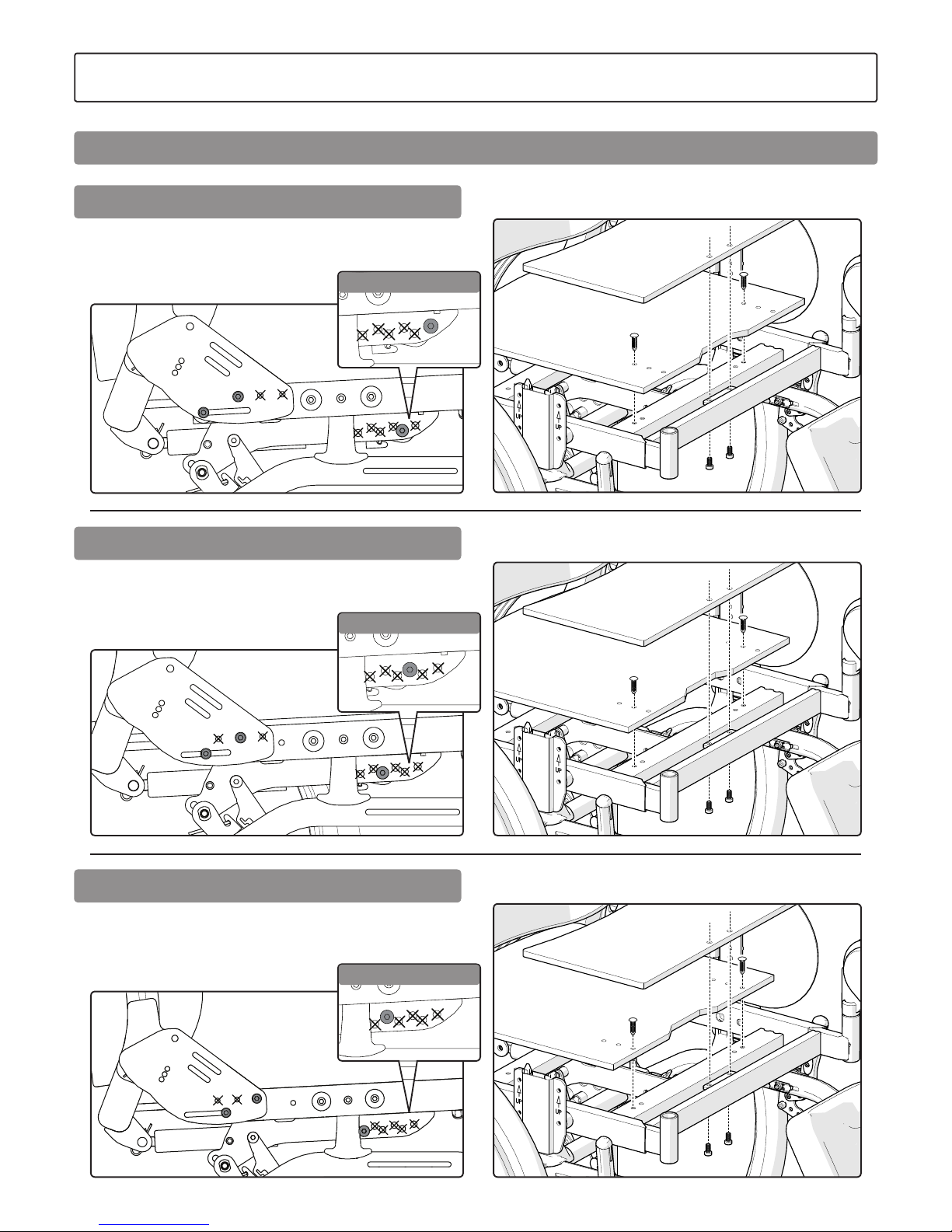
8. Secure the gas spring in accordance with the illustrations for
”Screw positions for seat depth”.
Do not forget the washer in between. NB! If fitted
into the wrong hole, the back support adjustment will
not function correctly.
9. Raise the chair up and remove the Allen key used to lock the back
support angle.
10. Fit the seat plates in accordance with the illustrations for ”Screw
positions for seat depth”. Start with
the rear seat plate.
11. Fit rear wheels, arm support and seat cushion.
12. Engage the anti-tips and check the seat and back angling
function.
Bear in mind the risk of tipping.
Always check the positioning of the anti-tips.
7. Settings
Seat depth, rear
Page 42
42
Etac / Prio / www.etac.com
Screw positions seat board
Screw positions seat board
Screw positions seat board
Screw positions for side frame/gas piston attachment. NB For a chair
equipped with electrical recline function, the above hole pattern applies – see illustration.
Screw positions for side frame/gas piston attachment. NB For a chair
equipped with electrical recline function, the above hole pattern applies – see illustration.
Screw positions for side frame/gas piston attachment. NB For a chair
equipped with electrical recline function, the above hole pattern applies – see illustration.
7. Settings
Screw positions for rear seat depth
Short seat depth 39-46 cm
Medium seat depth 41.5-48.5 cm
Long seat depth 44-51 cm
Electrical recline function
Electrical recline function
Electrical recline function
Page 43
43
Etac / Prio / www.etac.com
12° 8° 4° 0°
1
2
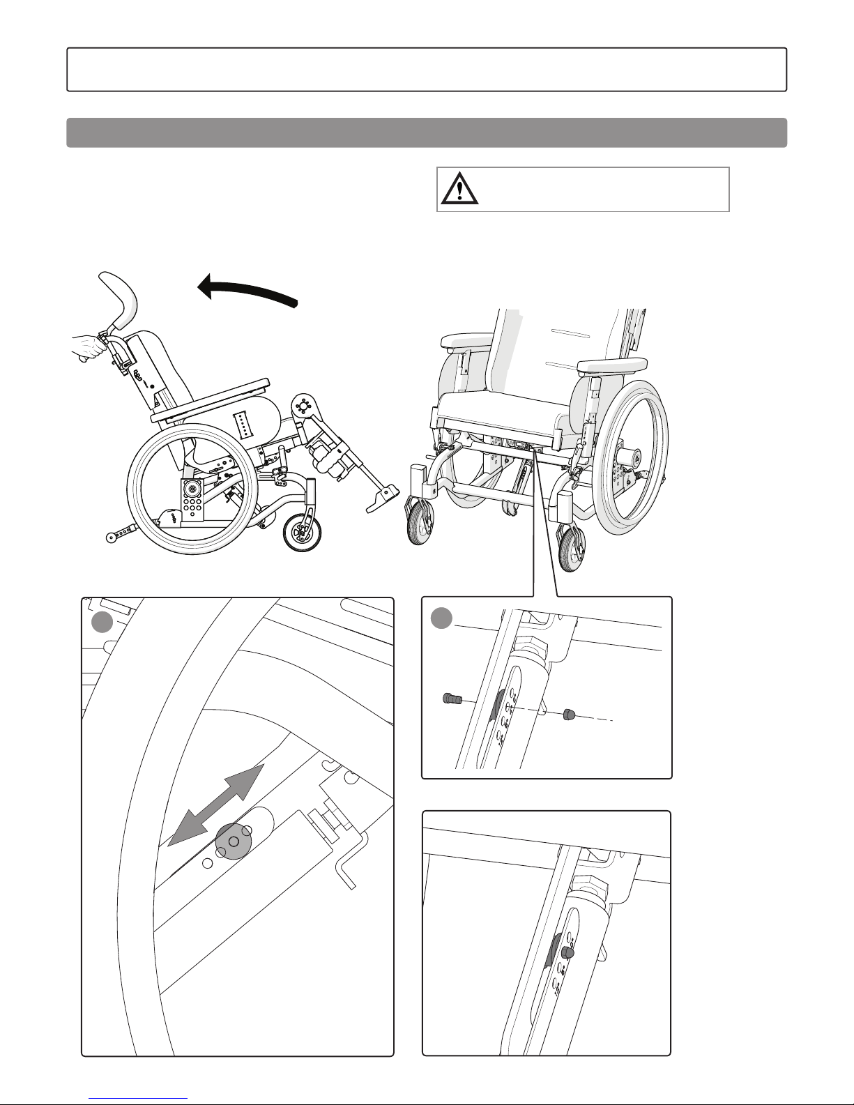
1. Undo screw and nut.
2. Adjust the seat angle for the comfort lock by moving and securing
the ball bearing bushing. The different angle options are marked
on the plate.
Bear in mind the risk of tipping.
Always check the positioning of the anti-tips.
7. Settings
Adjustment of comfort lock
Page 44
44
Etac / Prio / www.etac.com
15-20 mm
5 mm
12 Nm
1
1 2 3
2 3
4
5
5 mm
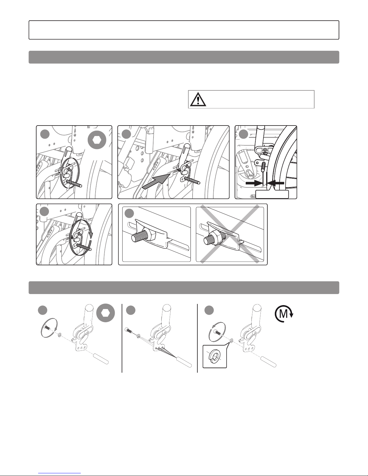
The brakes are variably settable
1. Loosen the screw a few turns.
2. Adjust the brake position
3. The brake block must be approximately 15-20 mm from the tyre
when the brake is not being applied.
4. Ensure that the brake is positioned straight in the track. Tighten
the nut with approximately 5 Nm.
Test the brakes!
5. Make sure that the nut is positioned correctly and locks into the
nut pocket on the inside.
The brakes are parking brakes and must not be used
as motion brakes.
8. Readjustments
Brake, adjustment
Brake lever adjustment
Page 45
45
Etac / Prio / www.etac.com
22”
20”
12 Nm
12 Nm
12 Nm
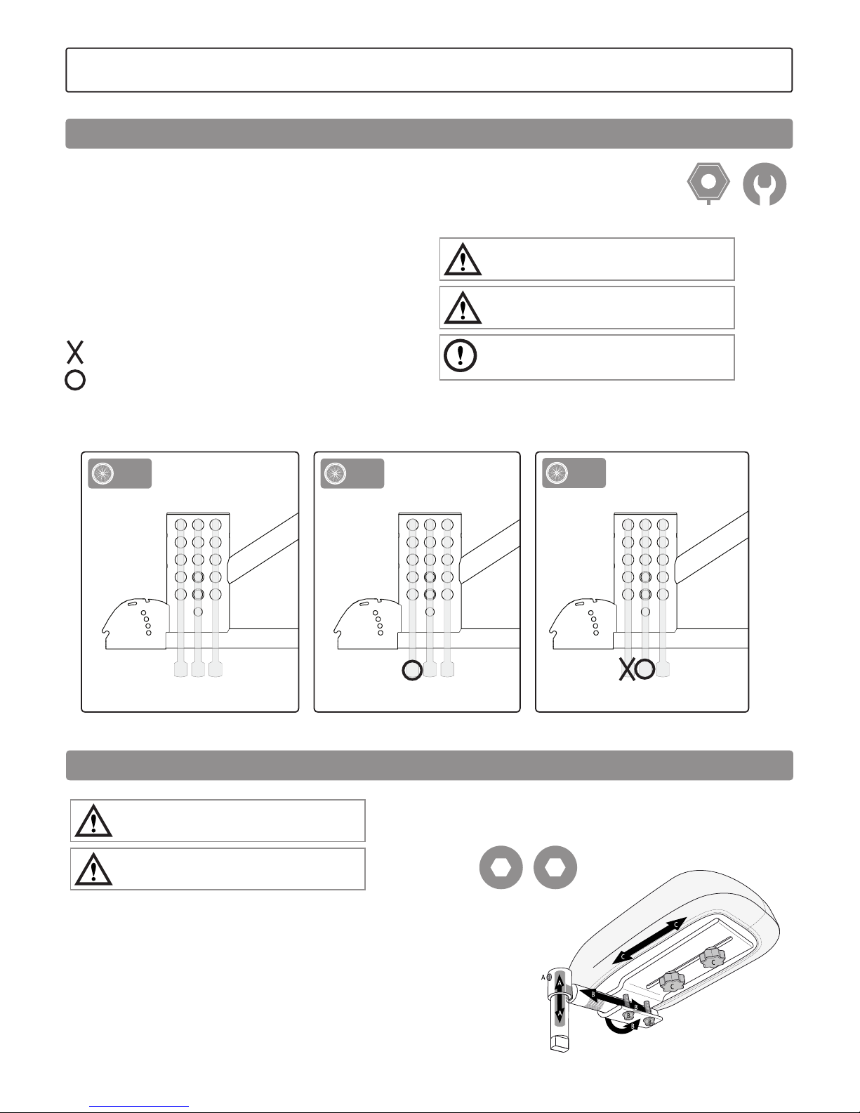
Brake adapter is required for the user brake to work with 20 "and
22" rear wheels (certain positions, see section "Adjustment of the
centre of balance").
See also section "Brake, adjustment".
8. Readjustments
Brake, mounting and adjusting adapter
Page 46
46
Etac / Prio / www.etac.com
3 2 1
3 2 1
3 2 1
24” 22”
20”
± 6 cm
4 mm 6 mm
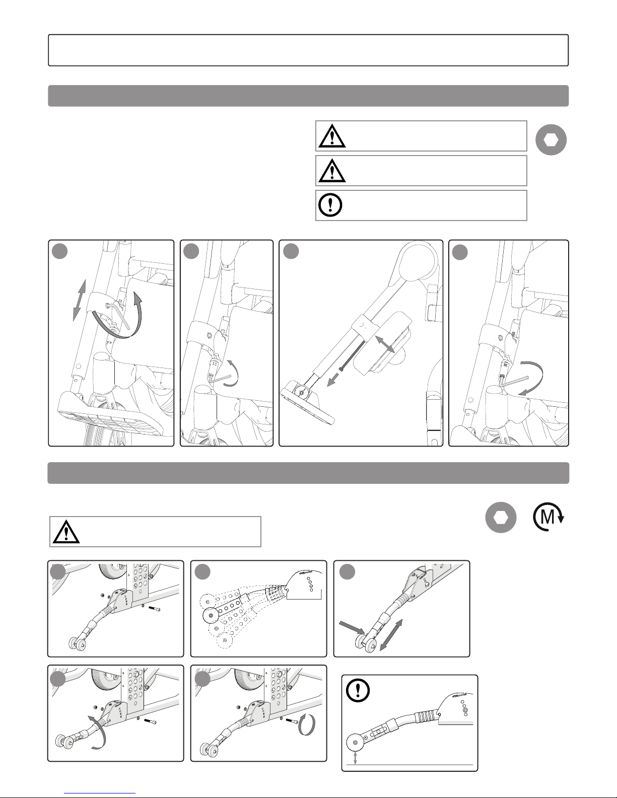
The centre of balance is adjusted by changing the position of the rear
wheels.
When the position of the rear wheels is moved forwards the wheelchair becomes much more manoeuvrable, but the tendency to tip
backwards increases.
- Move the hub sleeves/rear wheels forward or backward (pos 1, 2,
3).
See section ”Seat height adjustment using the rear wheel position”.
- Adjust the user brake, see Section ”Brake, adjustment”.
There are restrictions, see illustration.
=inadequate user brake function
= brake adapter required, see section "Brake, mounting and
adjusting adapter”
24 mm 17 mm
Bear in mind the risk of tipping.
Always check the positioning of the anti-tips.
Ensure that rear wheels with quick release hubs
are mounted securely.
The centre of balance is also altered when the seat
and/or back support angle are adjusted.
8. Readjustments
Adjustment of the centre of balance
Never sit on the amputee leg support.
Don’t lift the chair by the leg supports.
The amputee leg support is height, depth, angle
and sideways-settable.
Amputee leg support
Page 47
47
Etac / Prio / www.etac.com
1
4
2 3
5 mm
30-70 mm
1 2 3
4 5
2 Nm
5 mm
The calf support is height and depth-settable.
1. Loosen the screw, adjust the height of the calf support and
tighten.
2. Loosen the screw that keeps the calf support in place.
3. Remove the screw and select the depth.
4. Insert the screw and tighten slightly. The calf support must be
movable.
Never stand on the footplates as there is a risk
of tipping!
Don’t lift the chair by the leg supports.
Always make sure that the screw and footplate
knob are installed even if the footplate is not used.
8. Readjustments
Elevating leg support with calf support
Anti-tips
The anti-tips are foldable, turnable and height-settable.
Bear in mind the risk of tipping.
Always check the positioning of the anti-tips.
Page 48
48
Etac / Prio / www.etac.com
4 mm
9. Accessories - adjustment, handling
Assembly instructions are always provided with accessories when they are supplied by Etac.
Instructions are also available on our website www.etac.com
Positioning belt
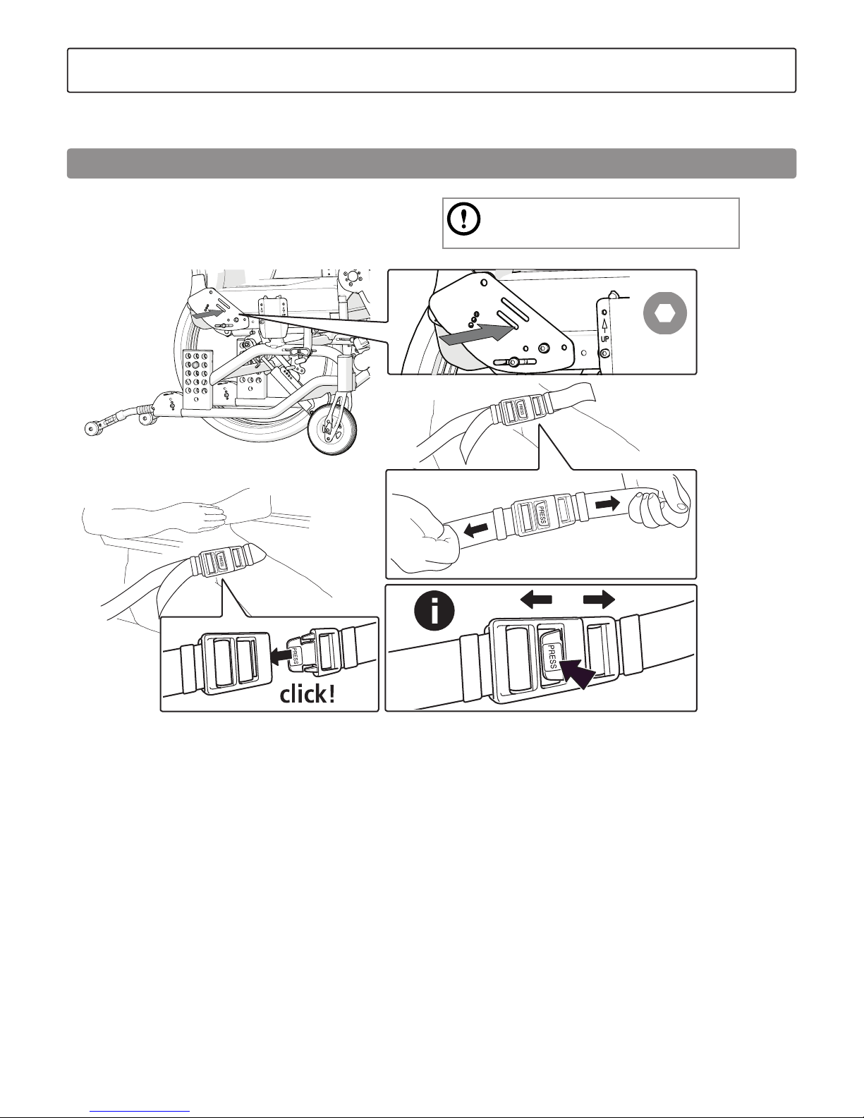
The positioning belt is in two parts, length-adjustable and equipped
with a snap lock. It is installed in the front part of the lower track in
accordance with the illustration.
Ensure that the user does not slide forwards in
the seat as this can lead to the belt impairing
the supply of blood to the hip/waist area.
Page 49
49
Etac / Prio / www.etac.com
1
2
3
54
5 mm
3 mm
The trunk support is height and depth-adjustable
and removable.
1. Loosen the screw on the side to adjust the trunk
support depth.
2. Loosen the screws on the rear to:
3. adjust the trunk support height
4. Loosen the knob on the rear to:
5. adjust the sides of the trunk support.
6. remove the trunk support from the chair.
9. Accessories - adjustment, handling
Trunk support
Page 50
50
Etac / Prio / www.etac.com
* The seat depth is measured from the front of the seat cushion to the middle of the back cushion.
** With arm supports, elevating leg supports, calf supports, rear wheels and anti-tips.
*** Without arm supports, head support, seat cushion, elevating leg supports, calf supports, rear wheels.
Max. incline
sideways
>20°
Max. incline
down
>20°
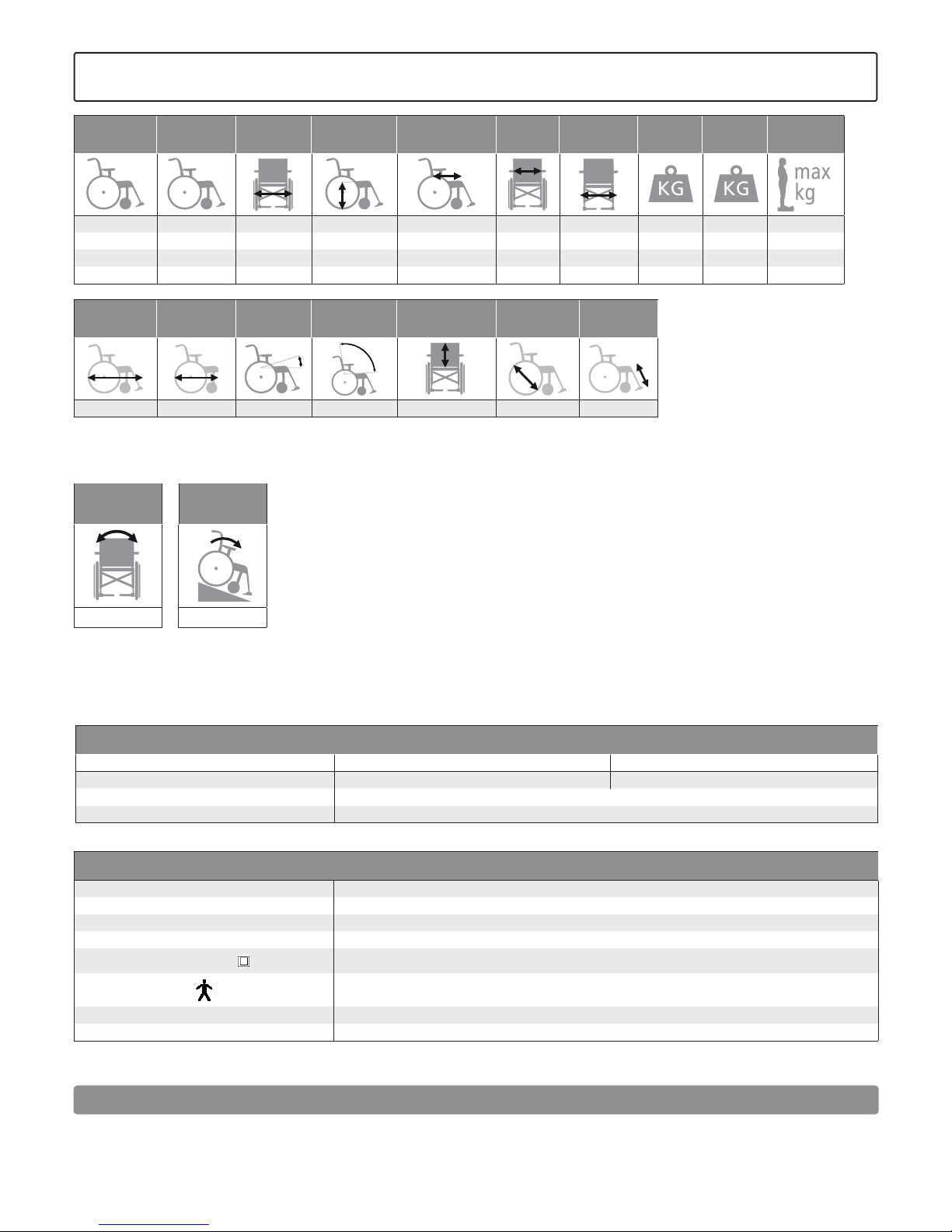
Type of chair Art. no. Total width Seat height Seat depth*
Effective
seat width
Transport
width
Weight**
Transport
weight***
Max.
user weight
40 cm 13420305 59 cm 38-52.5 cm 39-51 cm 40 cm 56 cm 33.5 22.9 135 kg
45 cm 13420309 64 cm 38-52.5 cm 39-51 cm 45 cm 61 cm 33.8 23.2 135 kg
50 cm 13420313 69 cm 38-52.5 cm 39-51 cm 50 cm 66 cm 34.1 23.5 135 kg
55 cm 13420317 74 cm 38-52.5 cm 39-51 cm 55 cm 71 cm 34.4 23.8 135 kg
Total length Folded length Seat angle Back angling
Back support
height
Handrim size
Leg support
length
101.5 cm 86.5 cm +3° — -20° 0° — -30° 55-70 cm 44.5-52.5 cm 33-61 cm
10. Technical data
Chair with electrical back and seat recline function
Operating environment
Long-term/short-term storage and transportation Operation
Temperature -10 - +40 +5 - +30
Relative air humidity 20 - 90%
Atmospheric pressure 700 - 1060 hPa
If the chair has been stored at a low temperature, it must be adapted to the operating conditions before use.
Electrical drive system
Supply voltage 100 - 240 VAC, 50/60 Hz (-15% +10%)
Maximum input current 3.9 A
Intermittent (periodic motor use) 5% 1 min constant use 19 min standby
Nominal voltage 25.9 V DC
Protection class
IPX6
The part in contact with the patient meets the requirements for protection against electric shocks in
IEC60601-1.
Degree of protection Class 2
Battery type Lithium ion
Complete information and user instructions for electrical components is available at www.linak.com, or contact your retailer or technical aids centre.
This product has been tested and complies with the EMC limit values
given in IEC 60601-1-2 for class B equipment.
This product has a very low radiation and should not interfere with
other equipment.
Electromagnetic compatibility (EMC)
Page 51
51
Etac / Prio / www.etac.com
12. Service and maintenance
General
Product maintenance should be adapted to use.
If there is a fault in your wheelchair, please contact your prescriber or
technical aids centre. A defective wheelchair must not be used.
If your chair needs reconditioning or repair, only original parts
from Etac or components with equal quality should be used.
Etac will not be held responsible for damage or injury caused
by use of non-original parts.
When necessary lubricate moving parts/joints with
bicycle oil or similar.
The product must be serviced by trained personnel only.
Washing the back support and seat
The back cover is made from two-ply polyester. It is removed
by unscrewing the end terminations on the back rail.
Then pull the cover upwards, remove the tension rods and
wash in accordance with the washing instructions on the label.
The covers for the seat and back cushion are removable and
must be washed in accordance with the washing instructions
on the label.
Rear wheel/castor
Spokes: Loose spokes can lead to wheel wobble. Consult
a cycle dealer or technical aids centre if it is necessary
to adjust the spokes.
Wheel axles: Clean the wheel axles from hair and dirt as necessary.
Ball bearings: Require no maintenance.
Handrims: If a handrim is damaged in such a way that it
can cause hand injuries, it should be replaced.
Brakes
Heavy dirt can have a negative effect on the brake mechanism. In
the event of adjustments, see Section ”Brakes, adjustment”.
Washing the frame
It is important, both for the sake of hygiene and for the longevity
of the chair, that the wheelchair is kept clean. It is equipped with a
drainage hole which ensures that it is easy
to wash and dry.
Clean the frame with a non-abrasive cleaning agent with
a pH level between 5 and 9, or with a 70% disinfectant solution.
Rinse and dry.
Chair with electrical back and seat recline function
Electrical components conform with protection class IPX6, which
means the product may be cleaned with a brush and water.
Do not rinse electrical components with a pressure washer.
Maximum washing temperature 20°.
Do not use chemicals on electrical components.
The battery charger must not be connected.
Internal cables must be connected.
Retract the actuator to the innermost position to avoid degreasing of
the piston rod.
For washing in a cabinet washer-disinfector, all electrical components
must be disconnected. See separate service manual at www.etac.
com.
Storage
Wheelchairs that are not used must be stored indoors.
Touch-up paint
For minor scratches and paint damage, touch-up paint
is available.
Separation at source/Waste
The product should be sorted in accordance with national regulations.
Batteries: hand in to battery recycling.
Motor and control box: hand in to electronics recycling.
CE marking, tests:
The product complies with the Medical Device Directive
93/42/EEC.
The products have been tested and comply with the requirements set
out in EN 12183, which includes ISO 8191-2.
Combination agreements exist, see www.etac.com.
Etac's wheelchairs have been tested in accordance with
ISO 7176-19. They have been crash-tested by the Technical Research
Institute of Sweden. Testing has been carried out
using restraining device UNWIN_WWR/ATF/K/R using a 3-point seat
belt 907523, Klippan Safety AB.
Service life:
The anticipated durability and service life of the main product is
at least five years when used as intended, and in accordance with
the safety instructions, reconditioning manual and maintenance
instructions available in the user manual. The main product comprises
the seat and back chassis. Other parts/accessories are managed in
accordance with the manual and reconditioning manual. The actual
service life may vary depending on how often and how intensively
the product is used, but is at most 10 years. If the product is
intended for use after the service life period specified by Etac, it is the
responsibility of the product owner to ensure product functionality in
accordance with the manual and reconditioning instructions. If this
cannot be ensured then the product should be taken out of use.
The following methods of surface treatment have
been used:
Lacquered surfaces = Polyester powder coating or ED lacquer
Non-lacquered aluminium parts = Anodised coating
Non-lacquered steel surfaces = Galvanised
Warranty:
5-year guarantee against material and manufacturing defects.
For terms and conditions, see www.etac.com.
Special adaptations:
comprise everything that falls outside the instructions and settings
in the manual. Wheelchairs specially adapted by customers are not
eligible for Etac’s CE marking. Etac’s guarantee no longer applies. If
there are any doubts concerning the adaptation, please contact Etac
for advice.
If the wheelchair is used in combination with another product,
neither product may keep the CE marking unless a combination
agreement is in place. Please contact Etac for up-to-date information.
11. Tests and Guarantees
Page 52

52
Etac / Prio / www.etac.com
Etac Sverige AB
Box 203
334 24 Anderstorp
Sweden
Tel 0371-58 73 00
Fax 0371-58 73 90
[email protected]
www.etac.se
Etac AB (export)
Box 203
334 24 Anderstorp
Sweden
Tel 46 371-58 73 30
Fax 46 371-58 73 90
[email protected]
www.etac.com
Etac AS
Pb 249,
1501 Moss,
Norway
Tel 815 69 469
Fax 69 27 09 11
[email protected]
www.etac.no
Etac GmbH
Bahnhofstraße 131,
45770 Marl,
Germany
Tel 02365-98710
Fax 02365-986115
[email protected]
www.etac.de
Etac Holland BV
Fluorietweg 16a,
1812RR Alkmaar,
Nederland
Tel +31 72 547 04 39
Fax +31 72 547 13 05
[email protected]
www.etac.com
Etac UK Limited
29 Murrell Green Business Park
London Road, Hook, Hampshire
RG27 9GR, United Kingdom
Tel 01256 767 181
Fax 01256 768 887
[email protected]
www.etac.com
R82 UK Limited.
Unit D4A, Coombswood Business
Park East
Coombswood Way, Halesowen
West Midlands B62 8BH
United Kingdom
Tel 0121 561 2222
Fax 0121 559 5437
[email protected]
www.etac.com
Etac A/S
Egeskovvej 12
8700 Horsens
Denmark
Tel 79 68 58 33
Fax 75 68 58 40
[email protected]
www.etac.dk
Snug Seat, Inc.
12801 E. Independence Boulevard
P.O. Box 1739
Matthews, NC 28106, USA
Tel 800 336 7684
Fax 704 882 0751
[email protected]
www.etac.com
Etac Supply Center AB
Långgatan 12
SE-334 24 Anderstorp
7 320451 405852
75341
 Loading...