

Et HP 036., HP 037. Operating Instructions Manual

Operating
Instructions
Pneumohydraulic controller
HP 036./HP 037.
en
BEA--206006-EN-04
1. Safey 2
2. Function 3
3. Variants 5
4. Mounting 7
5. Installation 9
6. Commissioning 10
7. Maintenance 14
8. Spare Parts 15
9. Technical Data 16
Pneumohydraulic controller HP 036./HP 037.
Page 2/16 BEA--206006-EN-04
1. Safey
1.1 Approved applications
1.2 Operating instructions
1.3 Mounting
The E+L controller HP 03.. must only be used to operate a hydraulic
positioning device.
Only use the controller
- if it is in perfect condition technically
- in accordance with its intended usage
- with an awareness of safety and risk factors and in compliance
with the operating instructions.
Any jobs regarding controller operation, gearing to production requirements, conversion, setting, its safety-related mechanisms, servi-
cing, maintenance and repair must be performed by qualied personnel only. Please observe the switching on/o procedure laid out in the
operating instructions.
Look after these operating instructions carefully and make sure they
are available to personnel at all times.
The operating instructions are part of the package and should be
read carefully prior to mounting, operation and maintenance work.
Please observe the locally applicable and customary safety and accident prevention regulations.
Hydraulic and pneumatic lines should be installed so that they do not
present any risk. There should be no bending (minimum bending radius 50 mm for lines supplied by E+L).
Operating elements that are a potential risk when pressure is reduced, e.g. bursting of the hose or motor standstill, should be appropriately safeguarded by the user.
Please ensure that:
- electrical components without enclosures such as switch panels
or operating devices are protected according to the locally applicable safety regulations, e.g. VDE 0100
- when laying electrical leads the customer shall ensure that the insulation is not damaged and that leads are correctly secured and
screened
- controller power is switched on along with the main machine system switch
- the controller is integrated into the machine control in such a way
as to prevent it starting up independently after a machine standstill
or an emergency OFF device reset.
The controller should be operated by qualied persons or suitably instructed personnel only.
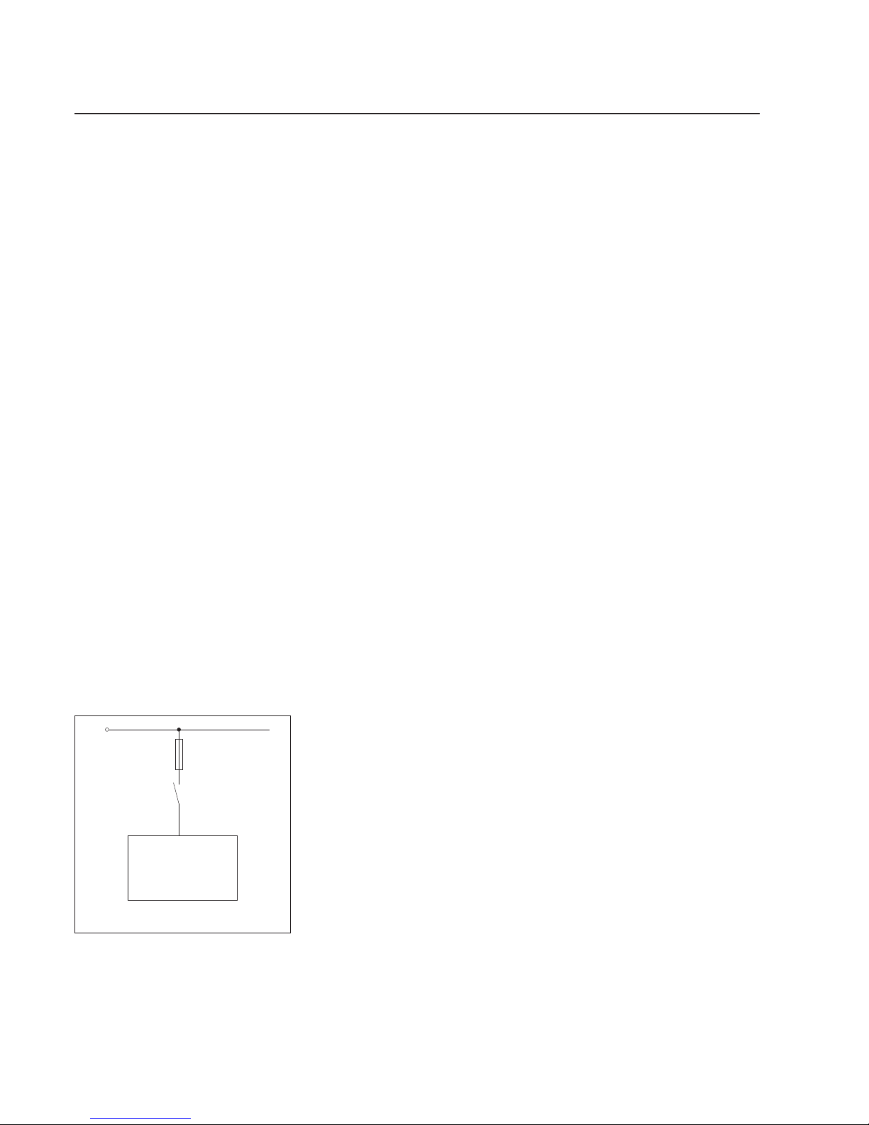
1.5 Operation
Main switch on
your machine
L 1
1-pole illustration
Controller
HP 03.. electric
control
1.4 Installation
BEA--206006-EN-04 Page 3/16
Pneumohydraulic controller HP 036./HP 037.
The HP 03.. controller is used to position actuators in web guiding
systems or in unwinding/rewinding stations. The controller is designed for systems guiding by the web edge with a pneumatic sensor
FL2.. .
2. Function
2.1 Purpose
HP 03.. controller
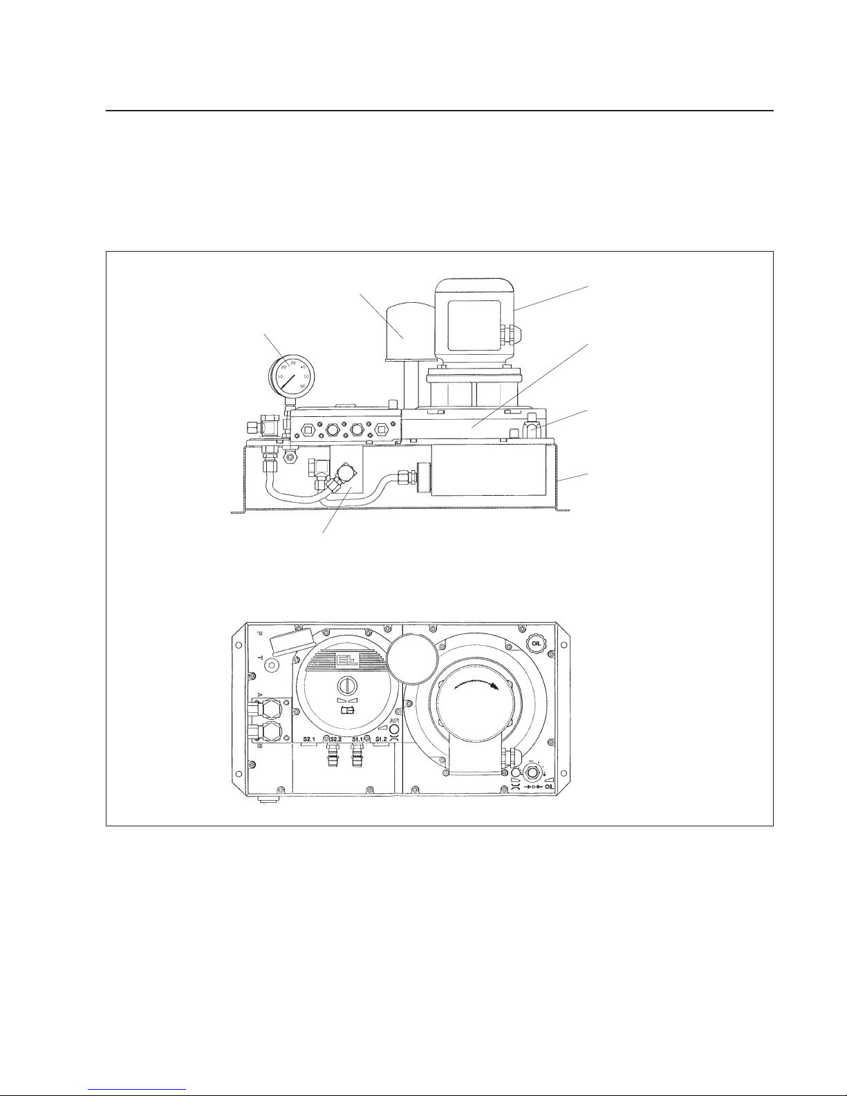
2.2 Design
Side channel compressor
Air intake lter
Servo-valve
Pressure gauge
Fluid tank
Pressure relief valve
Three-phase a.c. motor
The HP 03.. controller is made up of the following components:
- three-phase a.c. motor
- side channel compressor
- air intake lter
- servo-valve
- pressure relief valve
- pressure gauge
- uid tank
Pneumohydraulic controller HP 036./HP 037.
Page 4/16 BEA--206006-EN-04
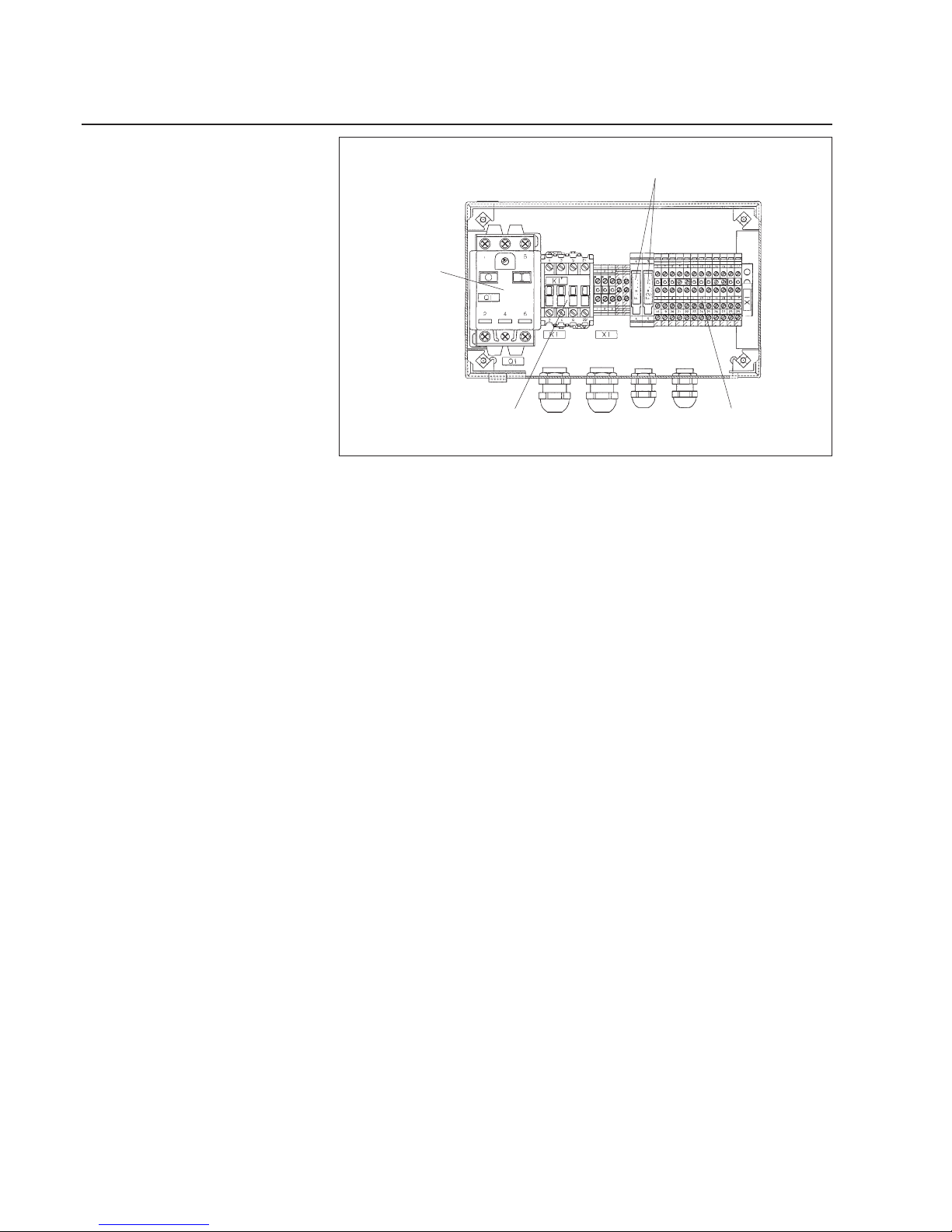
2.3 Mode of operation
Motor protec-
tion switch
Contactor
Fuses
Switch panel SE 12521
Connection terminals
The HP 03.. controller is available in three dierent electrical versions.
- Switch panel SE 12521 with motor protection switch, three-phase
a.c. motor contactor and connection terminals for the valve wiring.
- Terminal box SZ 0921 with connecting terminals only for the threephase a.c. motor and valve wiring.
- No electrical wiring.
To generate the air required for sensing, ambient air is drawn into the
side channel compressor and fed to connection S 1 of the pneumatic
sensor. The level of the probing air pressure and thus the control
sensitivity for adjustment to dierent situations is set via a restrictor.
Some of the compressed air is sent to diaphragm D 1 (see pneumatic system plan on opposite page, at top). A pressure spring works
in the opposite direction to the dia grapm. If the sensor is covered appropriately, the diaphragm is maintained in the center and the system
in a zero position.
If the web moves away from the zero position, it changes the air cur-
rent which, in turn, inuences the diaphragm. The change to the diaphragm directly aects the servo-valve controlling the uid ow. The
uid ow changes the location of the positioning cylinder until the
web returns to its zero position.
BEA--206006-EN-04 Page 5/16
Pneumohydraulic controller HP 036./HP 037.
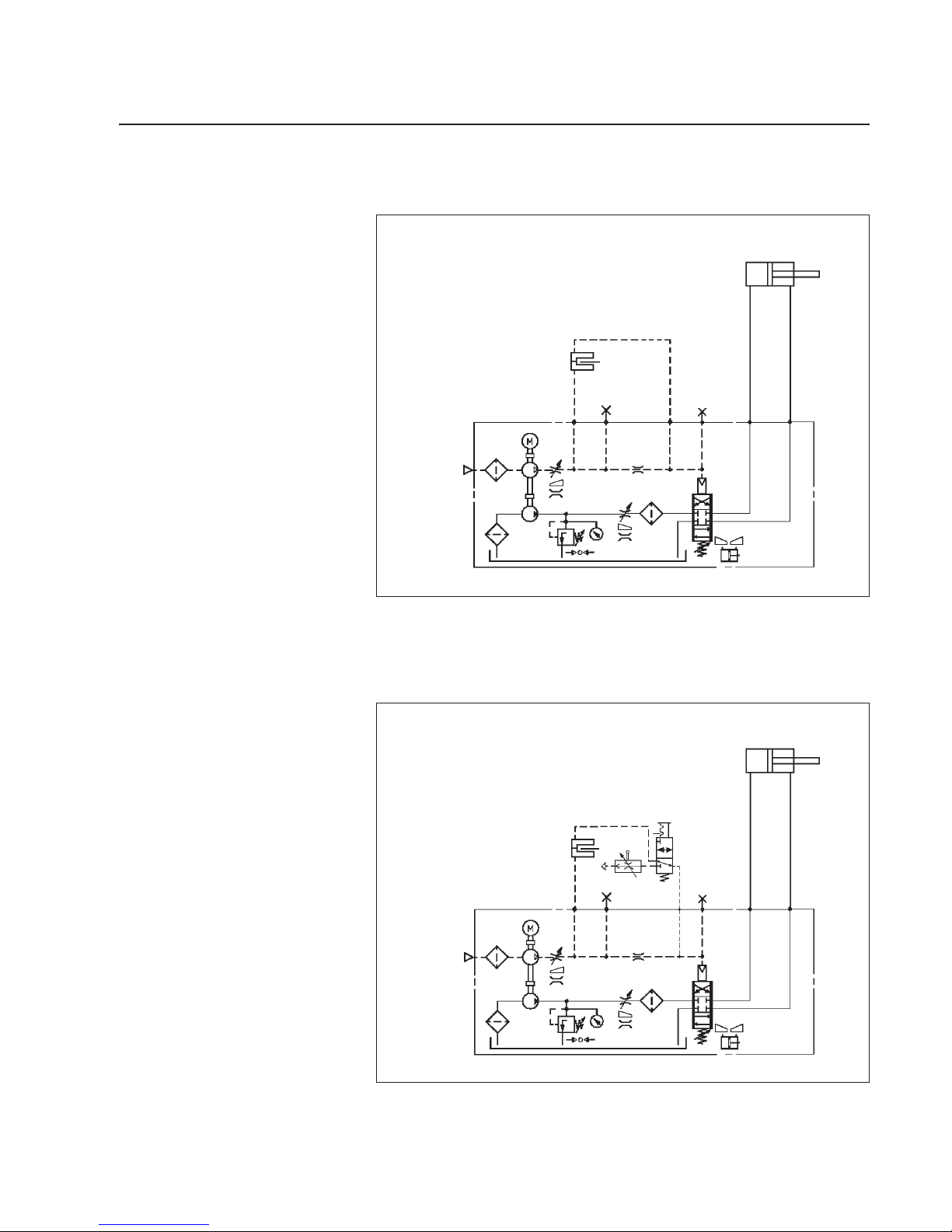
On the basic model HP 03.. without valve assembly, guiding by the
web edge only (automatic) is possible.
:S 1.1 :S 1.2
:S 2.1 :S 2.2
- HZ
:S 1
- FL
AIR
T
AP
T
P
OIL
HP 0360 20 bar
HP 0370 30 bar
B
:A :B
D 1
:S 2
FL = pneumatic sensor
HZ = positioning device
P
D 1
- FL
AIR
:S 2.2
OIL
- SC
T
:S 1
:S 2
:S 1.1 :S 1.2
:S 2.1
P
A
B
T
HP 0360 20 bar
HP 0370 30 bar
:A
:B
- HZ
- V 1
FL = pneumatic sensor
HZ = positioning device
SC = servo center actuator
V 1 = manually-actuated valve
Valve assembly 02 permits guiding by the web edge (automatic) or
servo center. Reversing is eected via a manually-actuated valve.
3. Variants
3.1 Basic model, system 1
3.2 Valve assembly 02,
system 2a
 Loading...