

Et BLUE-ROLL Installation Manual
ET BLUE-ROLL
Domestic type roll-up garage door operator
Installation manual
Revision Oct.08.002
support@et.co.za
Technical specifications may change without prior notice.
All goods are subject to the standard factory warranty as laid out on the last page of this publication
15 Nelson Rd, Observatory, Cape Town, South Africa
G&C Electronics cc. T/A ET Systems
www.et.co.za
1

We strongly recommend that a set of safety infra red beams (ET BLUE I’s) be used for additional
protection.
DO NOT operate the Garage door operator while a person, especially a child is near the door.
Children must be under adult supervision at all times near an automated garage door especially
whilst the operator is in use.
Ensure that the BUILT IN SAFETY OBSTRUCTION SENSING SYSTEM (Load sensing) is correctly setup.
Regular testing (Monthly) is advised and adjustment must be made if necessary.
DO NOT pull the Manual release cord that changes the operator to manual operation whilst any
person or object is near or under the path of the door. If possible always change the operator to
manual mode with the door in the full closed position.
Connect the operator’s 220Vac mains cord to properly earthed mains. Installation and wiring must
comply with local council electrical code. (Enquire at your local municipality for a certified electrician
if uncertain)
DISCONNECT electrical power before undertaking any repairs to the garage door operator. Only
experienced professional personnel should remove the covers.
Keep hands and or other parts of the body, as well as loose items of clothing, clear of the door and
operator while operating or servicing.
In applications where “auto-close” is required, a set of safety infra red beams (ET BLUE I’s) MUST be
installed. The safety device must be tested regularly (Monthly) for correct operation. EXTREME
CAUTION is necessary when setting an operator to “auto-close” mode. Safety rules must be adhered
to at all times. Some regions SAFETY CODES OF PRACTICE disallow the use of “auto-close” in garage
door automation. If uncertain rather don’t make use of this feature, or investigate further.
The SAFETY OBSTRUCTION SENSING SYSTEM (Load sensing) is only activated when a certain level of
resistance (Resistive Force) is exerted onto both the door and object/person obstructing the travel. As
a result, the object/person may suffer a degree of DAMAGE or INJURY relative to the SAFETY REVERSE
SYSTEM (Load sensing) setting. It is strongly recommended that SAFETY INFRA RED BEAMS (ET BLUE I’s)
be installed to increase the safety level.
Ensure that the door is fully open before passing through the doorway and fully closed before leaving
the area.
Keep the door in CLEAR LINE OF SIGHT whenever operating.
2
PRE-INSTALLATION INSTRUCTIONS
1. PRE-INSTALLATION PREPARATION
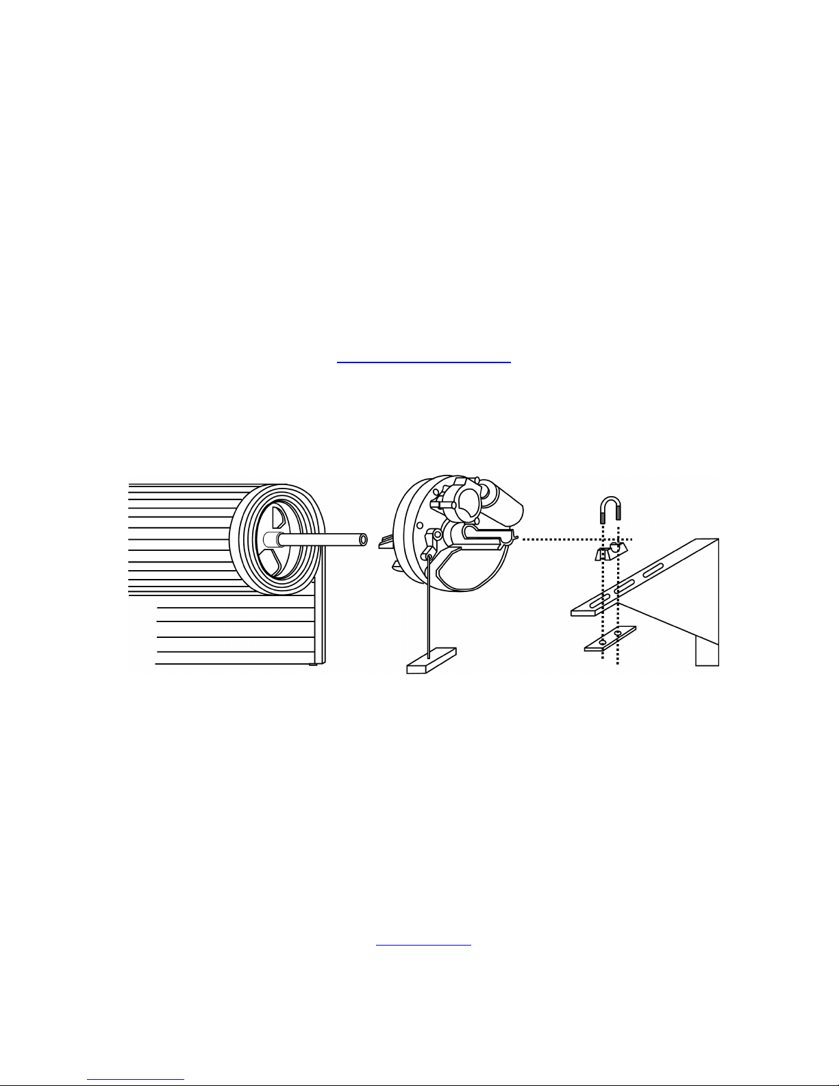
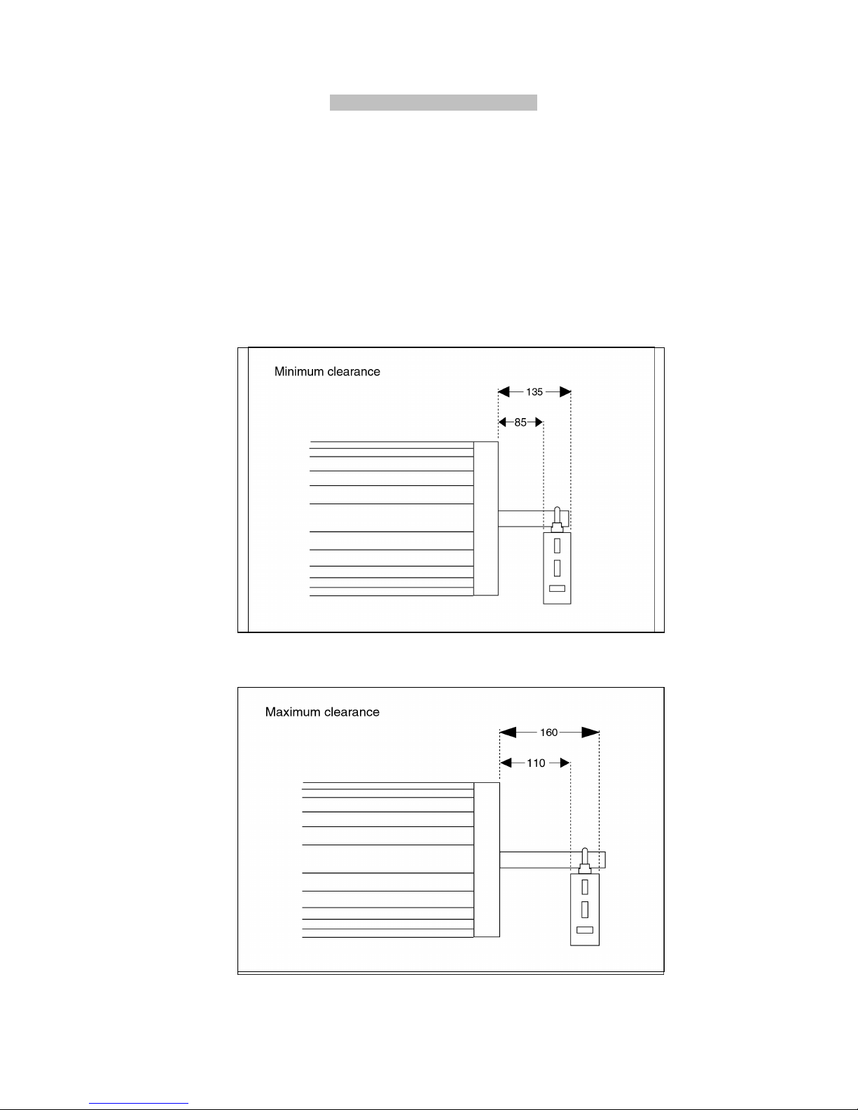
1.1. Ensure sufficient side room space:
Minimum side room of 85mm from the face of the door drum wheel to the inside edge of the door support
bracket is required to install the opener (see Fig. 1) and maximum side room is 125mm before having to
move and re-fit the support bracket or install the drive unit fully inside the drum (Fig. 7)
1.2. Ensure reasonable door condition and operation:
Before beginning the installation of the opener, check the operation of the door. The door must be well
balanced and be in reasonable condition. In general, the door should stay unmoving at around 900mm
and 1200mm above the floor. The door should not stick or bind in the guide tracks. The ideal operational
effort in raising or lowering the door should not exceed a force of 15kgF.
Fig. 1
Fig. 2
3
INSTALLATION INSTRUCTIONS
WARNING: EXTREME CARE SHOULD BE TAKEN TO PREVENT ANY POSSIBLE DAMAGES
2. INSTALLING THE OPENER ONTO THE DOOR SHAFT
There are various methods on how to install an opener to the door. The following is the most typical method.
CAUTION: THE INSTRUCTIONS SHOWN HERE ARE FOR RIGHT-HAND INSTALLATION
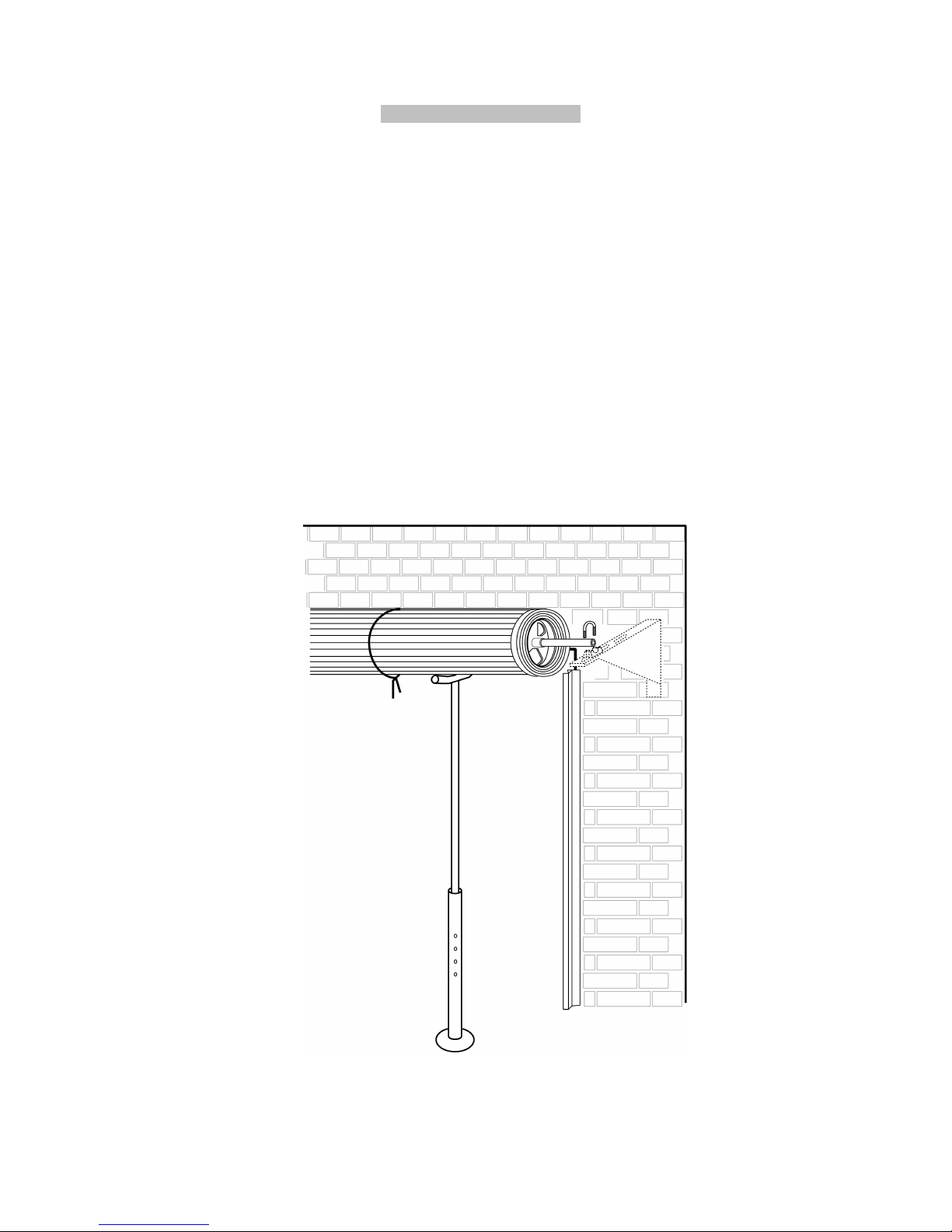
2.1 Roll the door up until the door curtain is out the door guides / tracks and use a rope to firmly tighten the roll in the
middle of the door (see Fig. 3).
2.2 Go to the opposite side of the door from where the opener is to be installed and ensure the U-bolts fastening the
door shaft to the bracket are firmly tightened. Pay extra attention here, otherwise the door shaft could loosen
when the U-bolt on the installation side is released.
2.3 Using a suitable prop, e.g. step ladder, together with soft padding to protect the door surface, support the door
on the right-hand side (see Fig. 3)
2.4 Loosen the nuts that secure the U-bolt on the right-hand side of the opener (opener installation side) and carefully
place the door onto the supporting prop. Remove and refit the door support bracket to a suitable side room
position, if required.
Fig. 3
4
2.5 Switch the opener into manual operation mode by pulling the manual release handle to enable the opener
drive to rotate freely.
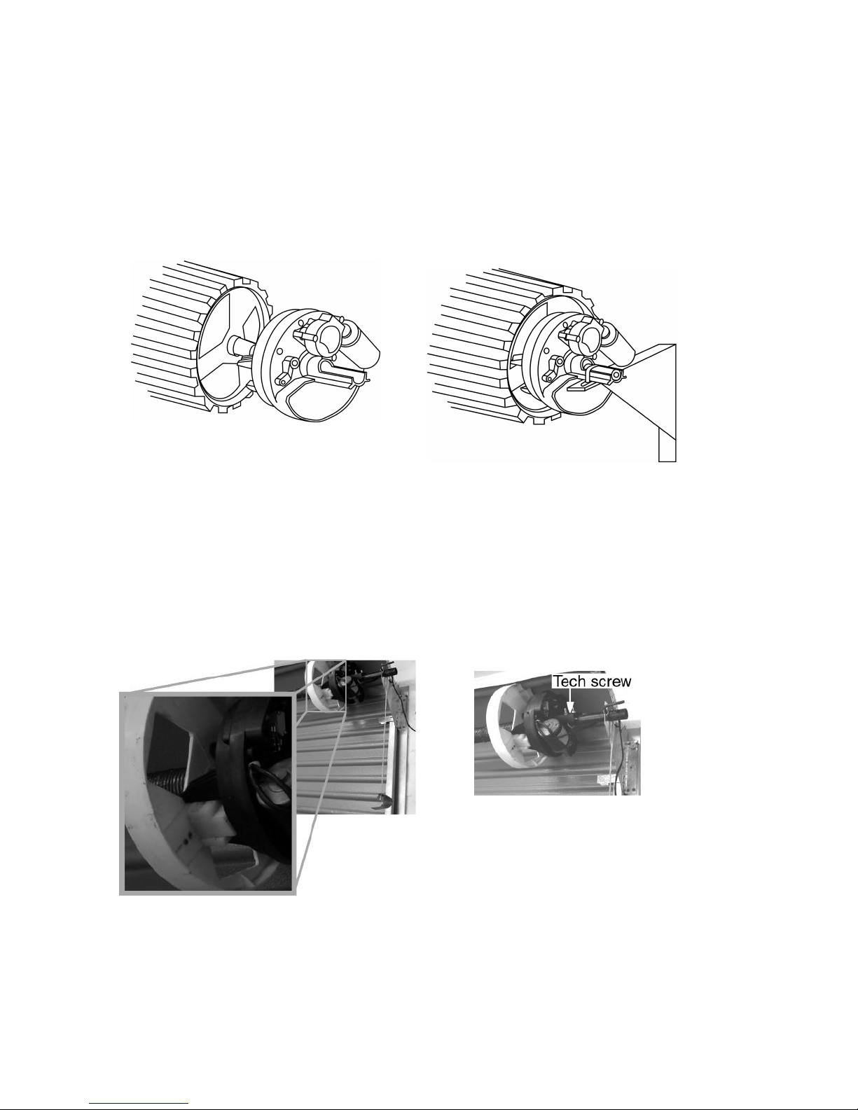
2.6 Raise the door carefully, insert the opener into the door axle and ensure the two opener forks hold the door drum
wheel support. Push the opener inside the door roll as deep as possible (Fig. 4). In cases where the drum spokes
do not match the drive fork, fasten a block of wood or similar material to the drum that will hold firm when driven.
(Fig 6). Use washers to prevent the fasteners tearing out of the drum wheel.
2.7 Re-position the door shaft on the door support bracket and fit the specially supplied U-bolt (Fig. 5) over the axle /
drive assembly and tighten firmly.
2.7.1 In cases where the unit is installed where it can not be fastened to the door support bracket as in Fig.7,
2.8 Remove the supporting prop, untie the rope and insert the door curtain back into its guides.
Fig. 4 Fig. 5
the addition of a self drilling tech screw through the base of the clamp into the torsion bar, may be
necessary after clamping the U bolt to the torsion bar. This will prevent the motor drive unit slipping
around the torsion bar which will cause the limit positions to drift.
Fig. 7
2.9 Manually open and close the door a few times to ensure the door runs freely and does not interfere with
unmoving parts of the opener. NB! Ensure the manual release cord is free from snagging and can be activated
easily. Care must be taken that the cord does not snag and become tangled in the drum as the door travels up
and down. Protect the cord from slicing and wear, if routed over the edge of the mounting bracket.
Fig. 6
5
PIN DOOR CURTAIN TO DOOR DRUM WHEEL
3.1 Pinning the door curtain to the drum wheel will reduce possible forced lifting of the door.
Close the door to the fully closed position and mark the two positions where the curtain is to be pinned onto the
drum wheel on either side of the door. The marked positions (pinning locations) should be at least 90
Fig. 8).
2.1 Raise door a little so that you can access the marked positions and pin curtain to drum wheel with self-drilling
tech screws or rivets.
Fig. 8
o
apart (see
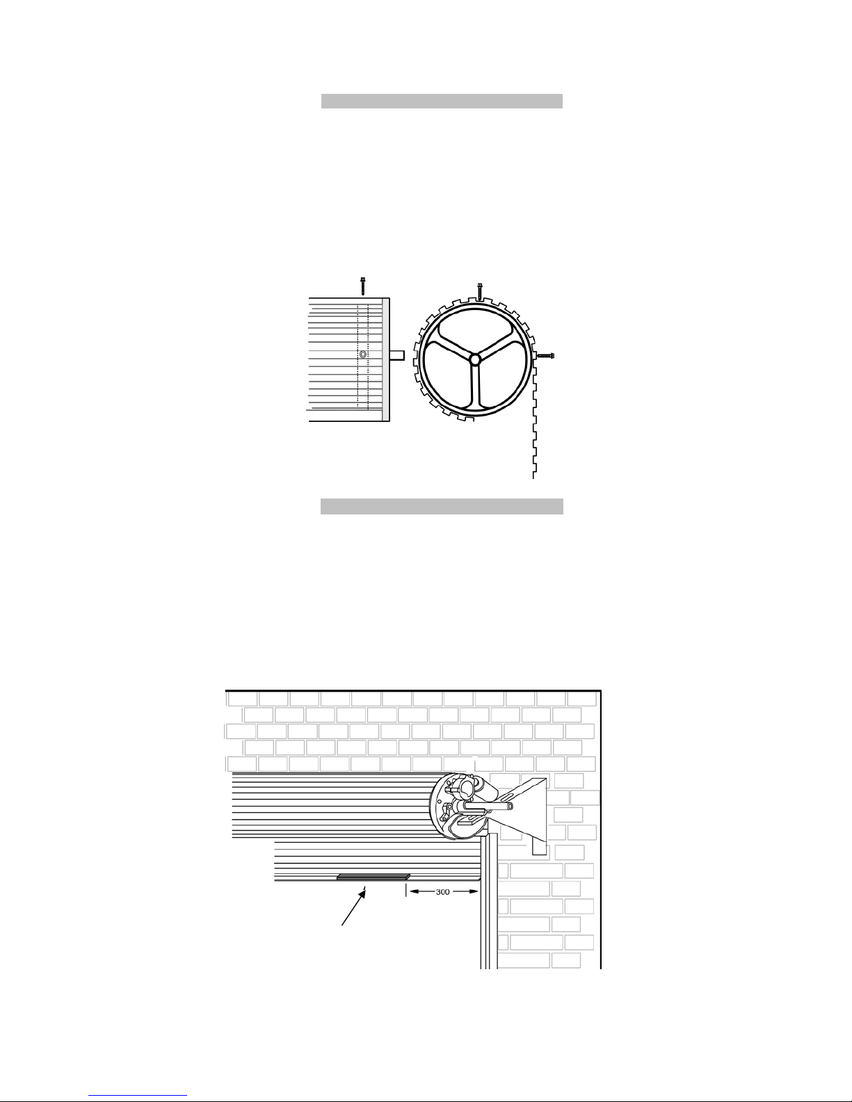
WEIGHT BARS (Optional – not supplied)
4.1 Weight bars may be required. Their main purpose is to eliminate the possibility of the door curtain ballooning on
initial start-up (from the door fully open position). After installing your new opener, if your door balloons on initial
start-up then we recommend that you fit one or two weight bars to the bottom edge of your door (total weight 57kg) as detailed below. (See Fig. 9).
4.2 Move the door manually to the mid-open position. If fitting one bar, centre it between either sides of the door. In
the case of two weight bars, fit them +/- 300 mm in from either side of the door. This ensures an even distribution
of the weight. Once the weight has been fitted the door should have a natural tendency to lightly freefall from
the mid-open position when in manual mode. The door should not drop rapidly!
Weight bar
Fig. 9
6
 Loading...