

Page 1
Page 2

c
eSync DVR Manual
Appendix A
Appendix A
FCC Compliance Statement
Model Name: eSync Series (SSA-1648e, SSA-0824e, SSA-0424e).
This device complies with Part 15 of the FCC Rules. Operation is Subject to the following two conductions: (1) this
device may not cause harmful interference, and (2) this device must accept any interference received, including
interference that may cause undesired operations.
WARNING
• Unauthorized reproduction of all or part of this manual is strictly prohibited.
• The figures in this manual are for illustration purposes only (may differ from the actual product).
The specifications and design of the product are subject to change without notice.
Revision A - 1 - © 2008 eSync Manual © eSyn
Page 3
c
eSync DVR Manual
Appendix A
CAUTIONS
To get the best use out of the eSync DVR, be sure to read the cautions before using the eSync unit.
For safety, please take note of the following:
• Before turning on the DVR
1. To prevent electric shock when installing, moving, or opening the DVR and peripheral devices,
disconnect the power cable.
2. Keep the packing materials used for the DVR or other peripheral devices out of reach of children.
• Installation Environment of the DVR
1. Maintain the following conditions: operating temperature of 32˚F ~ 96˚F; operating humidity of 10% ~
80%
2. Install the DVR in a safe place that is free from external vibration.
3. Install the DVR in a well-ventilated place.
4. To protect the hard disk from data loss and breakdown, install the DVR away from magnetic materials.
5. When using a rack other than the standard one, use a separate table with sufficient spacing, i.e., 20
inch from the floor, 18 inch from the ceiling, and 8 inch from the side and back walls and other objects.
• Safety Notes on the DVR
1. When installing Application HDD, turn OFF the DVR and remove the power cable completely.
2. Keep the product away from heat-generating devices such as heaters.
3. Do not use a damaged power cord.
4. To prevent problems due to magnetic interference and electric surge, use only grounded power cables
and power outlets.
5. If the power cord is connected, do not touch the power supply unit inside of the DVR (if the power cord
is connected, electric current is still flowing internally even after the switch is turned OFF).
6. Do not place a heavy object on top of the product.
7. Do not drop a conductive object in the ventilation holes.
8. Allow sufficient space for system cabling, such as (i.e. HDD SATA Cable, SATA Power cable, etc.)
9. Use only the parts indicated in the manual. Do not disassemble, repair, or modify the product without
permission.
10. Incorrect system setup may cause malfunction.
11. Shut down the system normally as instructed in the manual.
• Safety Notes on the Lithium Battery
1. Replace lithium batteries as instructed to avoid danger.
2. Dispose of used lithium batteries properly.
Warnings and Cautions are indicated as follows:
Possible injury or product damage
Risk of minor injury or product damage
Revision A - 2 - © 2008 eSync Manual © eSyn
Page 4

c
eSync DVR Manual
Table of Contents
Appendix A ..................................................................................................................................................1
FCC Compliance Statement .........................................................................................................................1
WARNING.....................................................................................................................................................1
CAUTIONS....................................................................................................................................................2
Chapter 1. Introduction...............................................................................................................................5
1-1 About the Product...............................................................................................................................5
1-2 Major Features ...................................................................................................................................5
1-3 Components.......................................................................................................................................6
Chapter 2. Installation and Connection....................................................................................................7
2-1 Name and Features of Each Panels ..................................................................................................7
2-1-1 Front Panel....................................................................................................................................7
2-1-2 Back Panel....................................................................................................................................8
2-2 Installation and Connection................................................................................................................9
2-2-1 Connection of Devices..................................................................................................................9
Chapter 3. Operation and Setup Tools ...................................................................................................10
3-1 Remote Controller ............................................................................................................................10
3-2 Mouse...............................................................................................................................................11
Chapter 4. System Operation...................................................................................................................12
4-1 Starting and Exiting the DVR............................................................................................................12
4-1-1 Starting the System.....................................................................................................................12
4-1-2 Exiting the System ......................................................................................................................12
4-2 Monitoring.........................................................................................................................................12
4-2-1 Screen Division and Automatic Screen Conversion...................................................................12
4-2-2 Menus in Live mode....................................................................................................................13
4-2-3 Relocating the recording status window .....................................................................................13
4-3 System Login....................................................................................................................................14
4-3-1 User Accounts.............................................................................................................................14
4-3-2 Login............................................................................................................................................14
4-3-3 Logout .........................................................................................................................................14
4-4 Audio Recording and Playback ........................................................................................................15
4-4-1 Setting up the Audio Recording ..................................................................................................15
4-4-2 Live Audio....................................................................................................................................15
4-5 Viewing System Information and Changing the Display Setup........................................................16
4-5-1 System Information.....................................................................................................................16
4-5-2 Channel Grouping.......................................................................................................................16
4-5-3 Adjusting the Screen Brightness.................................................................................................16
4-5-4 Adjusting the Screen Contrast ....................................................................................................17
4-5-5 Camera Position Adjustment.......................................................................................................17
4-5-6 Display Control............................................................................................................................17
4-5-7 Display/Hide Camera Name........................................................................................................17
4-5-8 Adjusting the Screen Border.......................................................................................................17
4-6 Spot Control......................................................................................................................................17
4-7 Relay Out..........................................................................................................................................17
4-8 Playback...........................................................................................................................................18
4-8-1 Shifting to Playback Mode...........................................................................................................18
4-8-2 Playback Menu............................................................................................................................18
4-8-3 Multi-Channel Search..................................................................................................................19
4-8-4 Multi-Time Search.......................................................................................................................20
4-8-5 Multi-Day Search.........................................................................................................................21
4-8-6 Playback Speed Control..............................................................................................................22
Revision A - 3 - © 2008 eSync Manual © eSyn
Page 5

c
eSync DVR Manual
Table of Contents
4-8-7 Playback on a divided screen .....................................................................................................22
4-8-8 Playback on Audio ......................................................................................................................22
4-8-9 Playback on Event ......................................................................................................................22
4-8-10 Go To The Date & Time Search ...............................................................................................23
4-8-11 Go To The First Search.............................................................................................................23
4-8-12 Go To The Last Search.............................................................................................................23
4-9 Log List.............................................................................................................................................24
4-9-1 Log Types....................................................................................................................................24
4-9-2 Viewing the System Log..............................................................................................................24
4-10 Recording .......................................................................................................................................25
4-10-1 Recording Types.......................................................................................................................25
4-10-2 Recording Setup .......................................................................................................................25
4-10-3 Viewing the Recording Status...................................................................................................25
4-10-4 Starting and Stopping Force Record.........................................................................................26
4-11 Search ............................................................................................................................................27
4-11-1 Selecting the Search Mode.......................................................................................................27
4-11-2 Selecting the Search Method....................................................................................................27
4-11-3 Search using the file list............................................................................................................27
4-11-4 Multi-Channel Search................................................................................................................28
4-11-5 Multi-Time Search.....................................................................................................................28
4-11-6 Multi-Day Search.......................................................................................................................28
4-12 Backup............................................................................................................................................29
4-12-1 Backup Method.........................................................................................................................29
4-13 Snapshot.........................................................................................................................................30
4-14 Direct Printing.................................................................................................................................30
4-15 PTZ Camera Control ........................................................................................................
4-15-1 Configuring PTZ Features.........................................................................................................31
4-15-2 Shifting to PTZ Mode ................................................................................................................31
4-15-3 PTZ Control...............................................................................................................................31
..............31
Chapter 5. System Setup..........................................................................................................................33
5-1 Main Setup........................................................................................................................................33
5-1-1 Starting the Main Setup...............................................................................................................33
5-1-2 Data Selection (Data 1 ~ Data 4)................................................................................................33
5-1-3 Shifting to Recording Setup Mode..............................................................................................33
5-1-4 Saving the Recording Settings....................................................................................................34
5-1-5 Recording Setup .........................................................................................................................34
5-1-6 Recording Schedule....................................................................................................................40
5-1-7 System ........................................................................................................................................42
5-1-8 Storage........................................................................................................................................47
5-1-9 NTP.............................................................................................................................................51
5-2 Application Setup..............................................................................................................................53
5-2-1 Selecting the Application Setup Menu........................................................................................53
5-2-2 PTZ setup....................................................................................................................................53
5-2-3 Network setup .............................................................................................................................55
Revision A - 4 - © 2008 eSync Manual © eSyn
Page 6

c
eSync DVR Manual
Introduction
Chapter 1. Introduction
1-1 About the Product
The eSync Series is a digital video recorder that can monitor, record, play, archive, network, and transmit video singal
from 4, 8, and 16 cameras depending on model. Using the front buttons, remote controller, mouse, and keyboard
controller the user can control the DVR. The eSync Series offers strong networking capabilities such as remote
monitoring and remote configuration up to 128 cameras.
Powerful network functions including remote monitoring and remote system configuration are also supported.
1-2 Major Features
• Stable Standalone DVR (Embedded Linux)
• Simutanous Video output
Monitor Output: 1 BNC, 1 VGA
Loop Output: 4/8/16 BNC
Spot Output: 1 BNC
• Real Time Live/Record/Playback FPS per channel
480/480/480fps: SSA-1648e @ CIF
240/240/240fps: SSA-0824e @ Half D1 & CIF
120/120/120fps: SSA-0424e @ Full D1 & Half D1 & CIF
• Compression type : MPEG4 (video) / G.723.1 (audio)
• Backup/Copy – Ethernet, IEEE1394, USB2.0
• System operation – Front Button / Remote controller / Network / USB2.0 mouse / Keyboard controller
• Audio Input
16 channel: SSA-1648e
8 channel: SSA-0824e
4 channel: SSA-0424e
• Various network interfaces
Cable modem, Ethernet, ADSL/DHCP client
• System automation (all features are remote-controllable)
• Watchdog Feature
• HDD in Line Fault Tolerance
• Network Time Protocol support
• Various recording modes
Auto, Continuous, Motion, Audio, Sensor recording
• Multiple Scheduled recording feature
• Multi-language support
• Automatic email notification for event
• PTZ control through RS485 communication
• Remote monitoring software/Remote monitoring through the web browser/Smartphone/PDA
• Storage device
Internal storage device: Max. of 4HDD / 4TB
External storage device: Ethernet, USB2.0 IEEE1394 RAID external storage device
Revision A - 5 - © 2008 eSync Manual © eSyn
Page 7

c
eSync DVR Manual
Introduction
1-3 Components
After unpacking the product, check whether the following accessories are included:
eSync CMS CD (e-Manual, CMS, PDA Viewer)
eSync User Manual
Remote Controller
Two AAA 1.5V batteries
Power Cord
Rack Mounting Handle
Revision A - 6 - © 2008 eSync Manual © eSyn
Page 8
c
eSync DVR Manual
Installation and Connection
Chapter 2. Installation and Connection
2-1 Name and Features of Each Panels
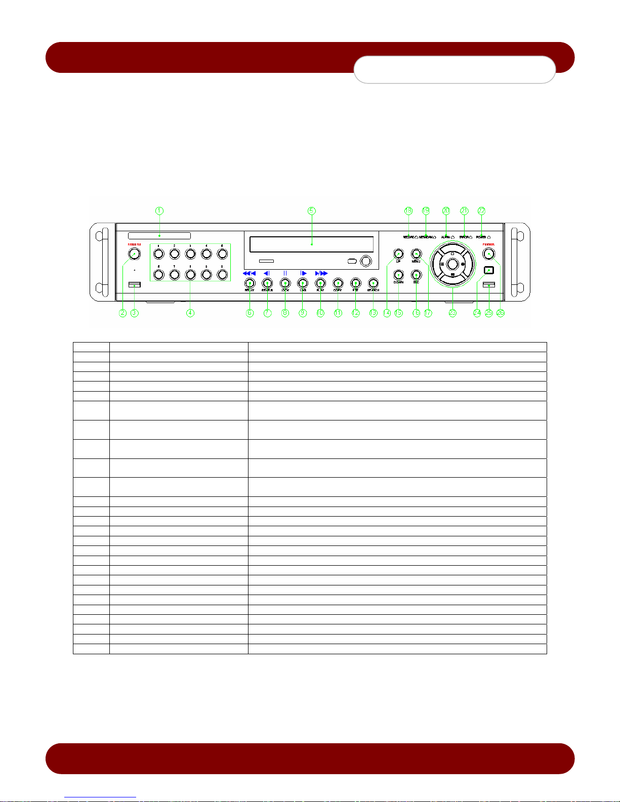
The front panel of eSync Series features easy-to-use buttons for various DVR features.
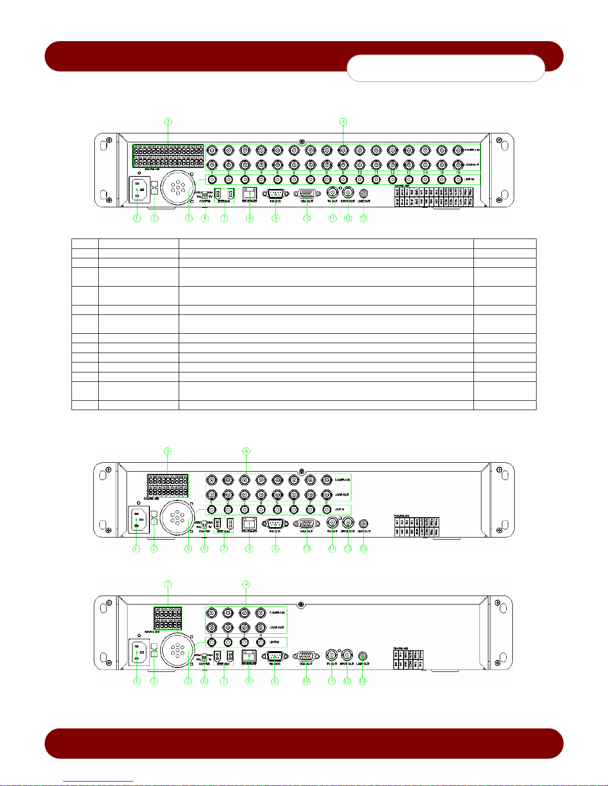
The back panel consists of all the connections of devices such as (i.e. camera, audio, RS485, sensor, relay, display
output, Ethernet, IEEE1394 Firewire, etc.)
2-1-1 Front Panel
No. Name Features
1 LABEL Model Number
2 RECORD Force Record
3 USB Connection ports to USB mouse and/or memory stick
4 Number Key buttons for System Logon and Channel Number
5 ODD DVD-RW
Reverse Play / Fast Reverse
6
RELAY
Reverse Frame by Frame or
7
STATUS
PAUSE
8
LOCK
9 Forward Frame by Frame or LOG
Forward Play / Fast Forward
10
PLAY
11 COPY Option to Backup, Snapshot or Print from Recorded Files
12 PTZ Control Assigned PTZ
13 SEARCH Open up search window
14/15 UP/DOWN Speed Control for Playback Mode and Volume Up/Down
16 ESC Button Exits the current menu or selects the upper menu
17 MENU Access Menu options for Live / Playback mode
18 RECORD LED Green LED turned on upon HDD operation
19 NETWORK LED Green LED turned ON during remote access
20 ALARM LED Red LED turned on upon the occurrence of event or motion
21 ERROR LED Red LED turned on upon fan defect or recording interruption
22 POWER LED Power On/Off
23 SELECT Selects the current menu or selection or enable automatic screen rotation
23 Directional Buttons Navigate selection through DVR menus and change the screen display mode
24 IR Sensor IR receiver for remote control
25 USB Port Connection port to the USB2.0 devices (i.e. mouse and memory stick)
26 POWER Button Turn the system power ON or OFF
Backward Playback/Rewind (in Playback mode)
Relay Control (in Live mode)
Backward Playback Frame by Frame (in Playback mode)
View Configuration Statistics (in Live mode)
Pause (in Playback mode)
Lock (in Live mode)
Playback Frame by Frame (in Playback mode)
View Event Log (in Live mode)
Playback/Fast Forward (in Playback mode)
Starts Playback Mode (in Live mode)
Revision A - 7 - © 2008 eSync Manual © eSyn
Page 9
c
eSync DVR Manual
Installation and Connection
2-1-2 Back Panel
• 16ch Back Panel (SSA-1648e/1624)
No. Name Features Type
1 AC POWER Power cable connection to the body
2 AC Selector Not Available for Americas eSync Model
3
4
5 AUDIO IN Audio input connection (1 Audio Per Channel) RCA
6
7 FIREWIRE Port for external backup device via Firewire IEEE1394
8 Ethernet ADSL, cable modem, and Ethernet 10/100 Base-T connection RJ-45
9 RS-232C Serial cable connection for keyboard controller, system upgrades & checking D-SUB 9P
10 VGA Connection for VGA Monitor D-SUB 15P
11 TV Connection for TV or CCTV display monitor BNC
12 SPOT
13 AUDIO OUT Audio output connection RCA
• 8ch Back Panel (SSA-0824e)
RS485
DIO
CAMERA IN
LOOP OUT
NTSC/PAL
VGA/TV
Connection for the PTZ - See chart on the lower right back panel for detail
Sensor/Relay extension board connect ion
Connection from the video camera
Connection for the video signal loop output
Used to select the video input format
Used to select the video output format
Connection for TV or CCTV monitor connection to output image from the channel
generating an event signal (full screen)
Terminal
Block
BNC
BNC
DA-2
BNC
• 4ch Back Panel (SSA-0424e)
Revision A - 8 - © 2008 eSync Manual © eSyn
Page 10

c
eSync DVR Manual
Installation and Connection
2-2 Installation and Connection
2-2-1 Connection of Devices
Connect the PTZ controller cable, audio input/output, network, and sensors as shown below.
1) PTZ Camera
Connect the PTZ data control cable to RS485 port on the terminal block on the rear side of the DVR.
Be sure to connect the PTZ data control cable to the proper terminals listed TRX+ and TRX- on the DVR.
2) SPOT Monitor
The Spot monitor can be connected to a CCTV monitor that displays eve nts when triggered.
SPOT: The Spot monitoring function displays video from the channel detecting an event (motion, sensor, or
sound) in full screen. Events are checked ever y second. If events are detected from mult iple channels, the latest
event is displayed.
3) Audio Input/output
Audio ports can be connected; 4/8/16 input lines and 1 output line.
4) Sensor/Relay
Connect to the rear side of the product using the cable.
A. Sensor Connection
Connect to the DIO input port of the terminal block.
Each input term inal can be connected regardless of the channel number.
Sensor types include Normal Close (NC) and Normal Open (NO).
For more information on setup by sensor type, refer to {Data Setup} {Event Setup} {Sensor}.
Normal Close (NC): Normally closed; opens when a signal is received
Normal Open (NO): Normally open; closes when a signal is received
B. Relay Connection
Relay signals to external devices such as LED, light, or siren.
Connect the external alarm de vice to the COM or Out port of the sensor/relay terminal blo ck.
Relay types include Normal Close (NC) and Normal Open (NO).
For more information on setup by sensor type, refer to {Data Setup} {Event Setup} {Sensor}.
Normal Close (NC): Normally closed; opens when a signal is received
Normal Open (NO): Normally open; closes when a signal is received
Sensor Input Relay Output
4ch DVR 4 1
8ch DVR 8 2
16ch DVR 16 4
Revision A - 9 - © 2008 eSync Manual © eSyn
Page 11
c
eSync DVR Manual
Operation and Setup Tools
Chapter 3. Operation and Setup Tools
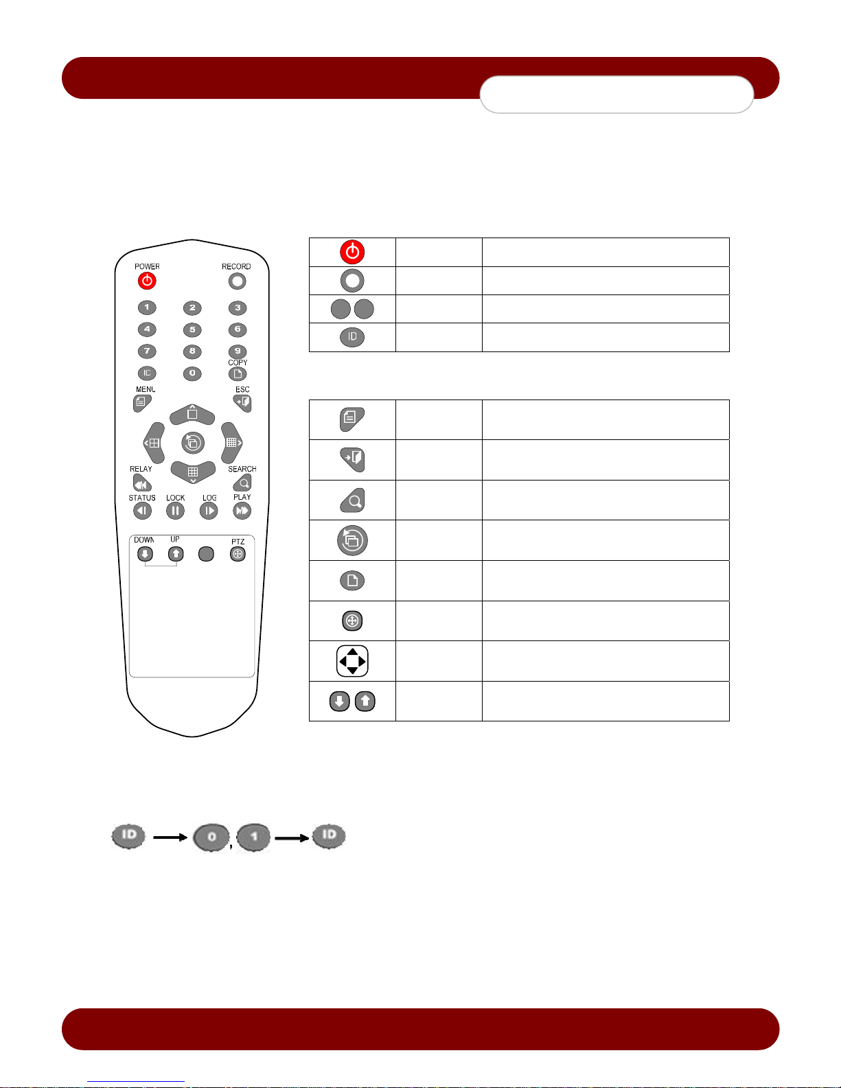
The user can easily operate the eSync DVR using the front buttons, remote controller, and mouse.
3-1 Remote Controller
A. Basic control buttons
POWER System power ON or OFF
RECORD Force record ON or OFF
1 0
NUMBER Enables input of numeric data
ID Sets up the remote controller ID
B. System operation and setup buttons
MENU Displays Menu options
ESC Exits the current menu
SEARCH Searches recorded files
SELECT
COPY
PTZ Control Assigned PTZ
MOVE
UP/
DOWN
Selects the current menu or selection or
enable automatic screen rotation
Option to Backup, Snapshot, or Direct Print
Recorded Files
Moves from one category to another or
changes the display mode
Speed Control for Playback Mode and Volume
Up/Down
Setting up the remote controller ID
To setup the remote controller ID to 1
Press the [ID] button, enter a two-digit remote controller ID, and press the [ID] button again.
Revision A - 10 - © 2008 eSync Manual © eSyn
Page 12
c
eSync DVR Manual
Operation and Setup Tools
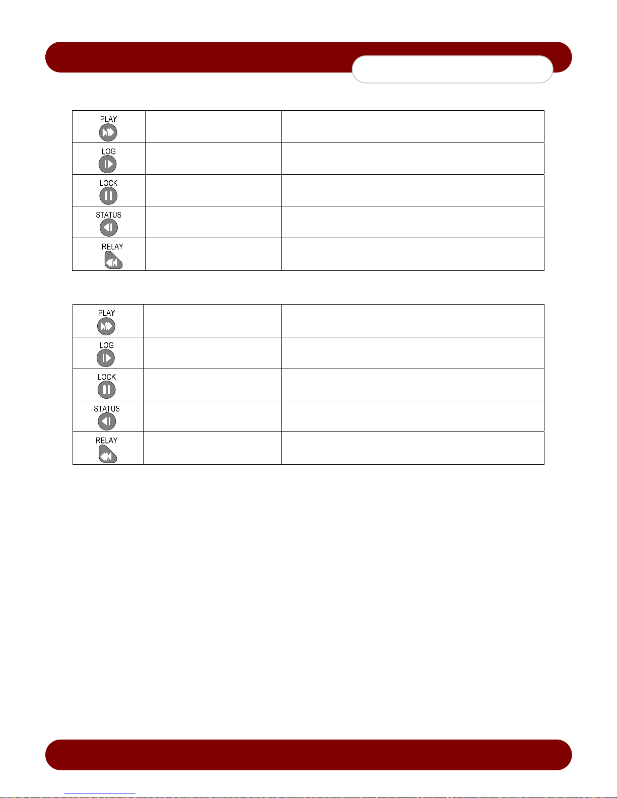
C. Buttons for other features in Live mode
PLAY Starts Playback Mode
LOG View Event Log
LOCK Locks the system
STATUS View Configuration Statistics
RELAY Relay Control
D. Search Button in Play mode
Play / Fast Forward Playback/Fast Forward
Frame by Frame Play frame by frame
Pause Pause
Reverse Frame by Frame Reverse play frame by frame
Reverse Play / Fast Reverse Reverse play/ Rewind
3-2 Mouse
The USB2.0 mouse (purchased separately) can be used to operate the DVR.
Revision A - 11 - © 2008 eSync Manual © eSyn
Page 13
c
eSync DVR Manual
System Operation
Chapter 4. System Operation
4-1 Starting and Exiting the DVR
4-1-1 Starting the System
With the power connected to the DVR, press the Power button on the DVR or the remote controller.
After the system is booted, images of all connected channels will be displayed.
• When powering up the DVR the boot process will enable th e eSync System Checker and Watch Dog
feature to ensure the proper performance of DVR.
• Booting time varies depending on the HDD size installed in the DVR due to HDD cluster check.
4-1-2 Exiting the System
The default password for the local admin istrator is “00000.”
To change the password, select {Main Setup} {System} {Local Administrator’s Password}.
1. Press the Power button on the DVR or the remote controller.
2. On the password input screen, enter a new password using the numeric buttons and the arrow keys.
3. After the authentication process is completed, the alarm sound will activate for 20 seconds, and the DVR
will be turned off.
4-2 Monitoring
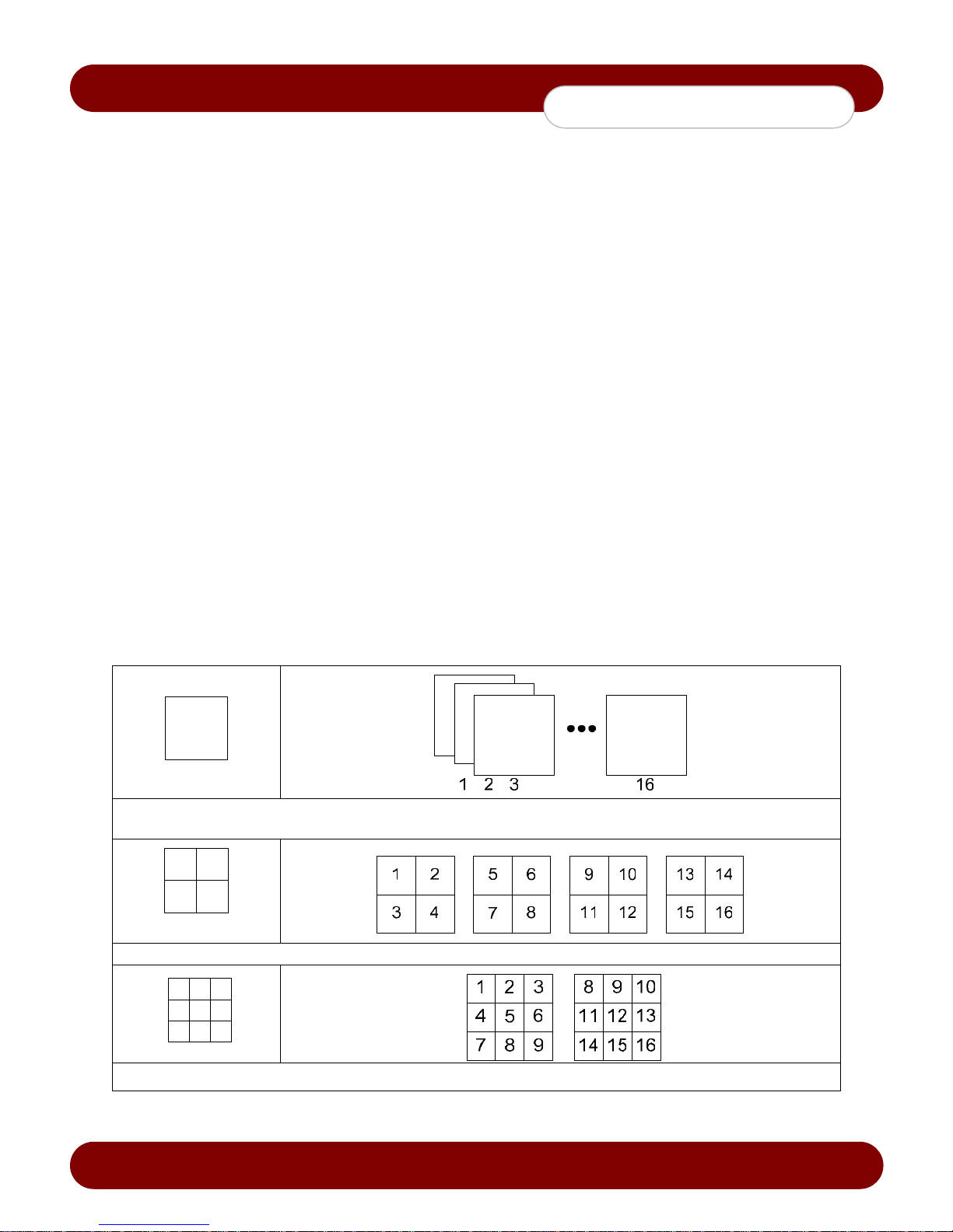
After the system is booted, images will be displayed on a screen divided into 16 sub-screens (in the case of 16channel DVR). The screen can be divided into 1, 4, 9, and 16 sub-screens. Auto-sequencing is available in each
mode.
4-2-1 Screen Division and Automatic Screen Conversion
Full Screen (16 groups)
4 Sub-Screens
(4 groups)
Use the Full Screen mode.
To view a certain channel, select the desired channel using the numeric buttons.
Use the 4 Sub-Screen button.
9 Sub-Screens (2 groups)
Revision A - 12 - © 2008 eSync Manual © eSyn
Use the 9 Sub-Screen button.
Page 14
c
eSync DVR Manual
System Operation
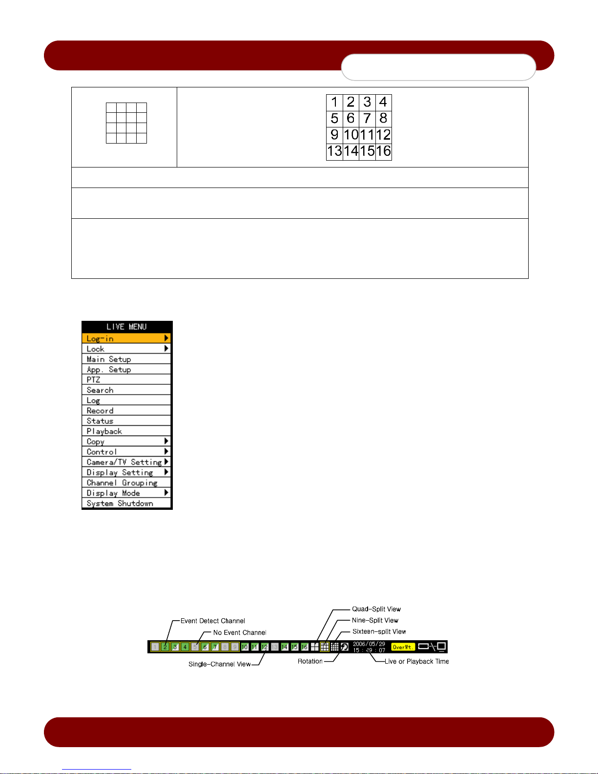
16 Sub-Screens (1 group)
Use the 16 Sub-Screen button.
※ The user can view an image on full screen by double-clicking the mouse on 4/9/16 Sub-Screen mode. Double-click the
mouse on any part of the screen to return to the previous mode.
※ The user can select the automatic change mode by selecting the [Select] button in 1/4/9 Sub-Screen mode.
Click the [Select] button again to return to the previous mode.
※ Using the Up/Down button, the user can change the time interval from 1 second to 5 seconds (to change time interval,
multiple cameras must be connected to the DVR).
※ The user can also change the time interval by right-clicking any part of the screen.
4-2-2 Menus in Live mode
In real-time Live mode, the user can control all functions using {Live menu}.
Press or right-click the Menu button.
The Live menu will appear as shown in Figure 4-1.
Select the desired item using the up or down arrow keys.
Press the ESC button or right-click the Menu button to hide the menu.
[Figure 4-1. Live Menu]
4-2-3 Relocating the recording status window
In Live mode window or playback mode, use the mouse to change the position of the recording status window.
1. The user can move the recording status window using only the mouse.
2. Move the cursor to the date/time status section. The recording status window will be bordered.
3. At this time, drag the recording status window to the desired location.
[Figure 4-2. Recording Status Window]
Revision A - 13 - © 2008 eSync Manual © eSyn
Page 15
c
eSync DVR Manual
System Operation
4-3 System Login
4-3-1 User Accounts
eSync DVR is divided into two different user levels; local administrator and general users.
Admin The local administrator can use all functions of eSync DVR. (only limited locally)
User
Functions
Network Live Enable live vieweing via network
Playback Enable playback via local and network
Copy (Download) Enable copying and downloading files from DVR via local and network
PTZ Control Enable PTZ camera control via local and network
Main/Application Setup Enable Local Administrator Privileges via local and network
Network Upgrade Enable Remote firmware upgrade via local and network
View Hidden Channels on Network Enables viewing hidden channels via network
4-3-2 Login
To use the Application Setup, Search, Playback, Copy, and Camera/TV Setup functions, the user must log in first.
Up to four user levels are allowed.
Each user can define the accessibility based on the features issued by the local administrator.
Administrator can access the accounts from {Main Setup} {System} {Add User}.
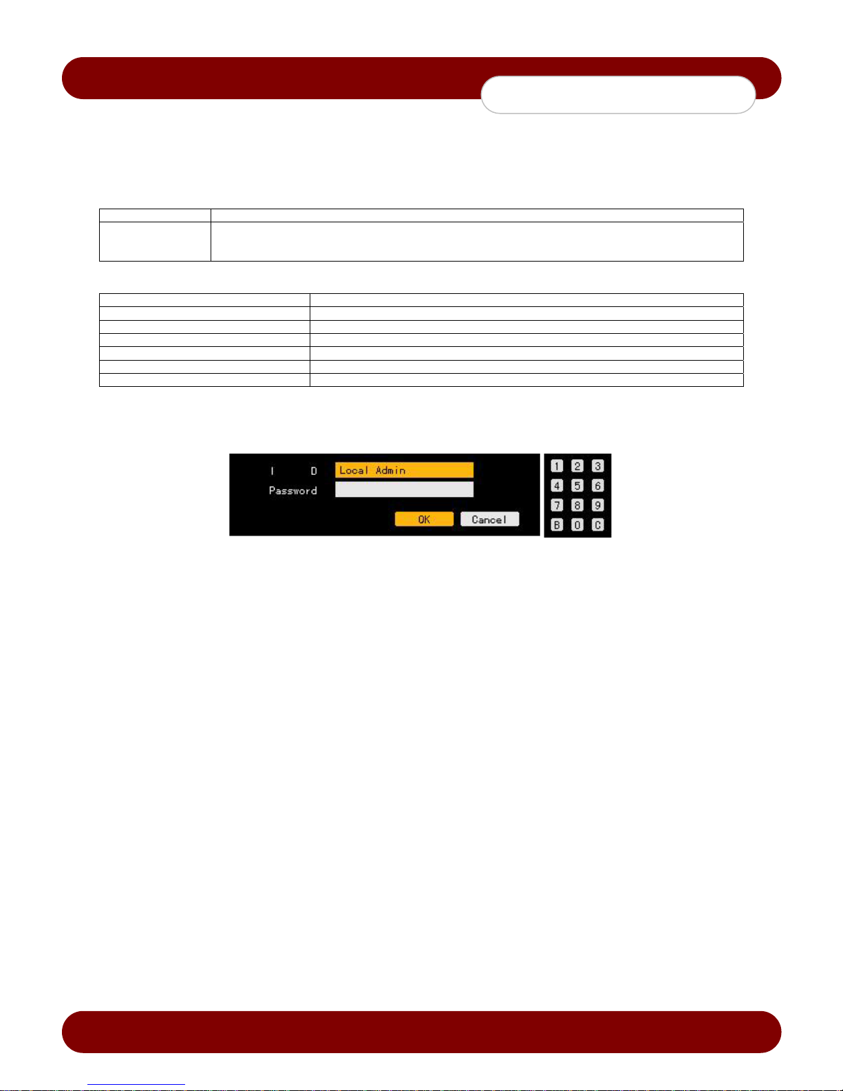
[Figure 4-3. Login Window]
On the Live mode window, press the {Menu Button} {Login}. The login window will appear as shown in Figure 4-
3.
Enter the default password: “00000”
4-3-3 Logout
After logging out, the user cannot use functions such as Main Setup, Application Setup, Search, Playback, Copy, and
Camera/TV Setup functions.
On the Live mode window, press the {Menu Button} {Logout}.
Revision A - 14 - © 2008 eSync Manual © eSyn
Page 16
c
eSync DVR Manual
System Operation
4-4 Audio Recording and Playback
4-4-1 Setting up the Audio Recording
1. On the Live mode window, press the {Menu Button} {Main Setup}.
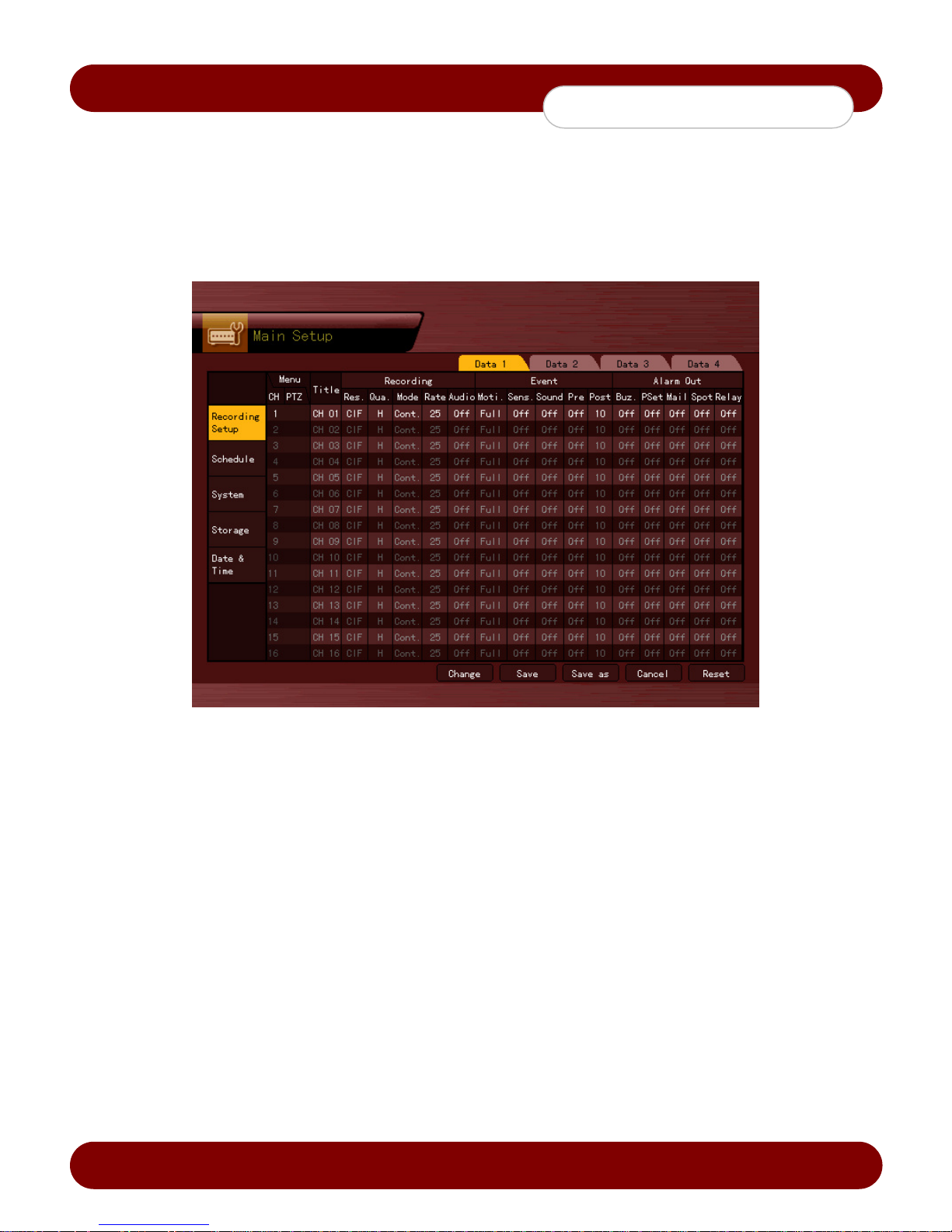
2. The main setup window will appear as shown in Figure 4-4.
3. Select {Recording Setup} {Recording} {Audio} using the arrow keys and press the [Select] button.
4. Set up the audio.
[Figure 4-4. Main Setup Window (Data Mode)]
4-4-2 Live Audio
1. On the Live mode window, press the {Menu Button} {Control} {Audio}.
2. Select the audio channel.
Revision A - 15 - © 2008 eSync Manual © eSyn
Page 17
c
eSync DVR Manual
System Operation
4-5 Viewing System Information and Changing the Display Setup
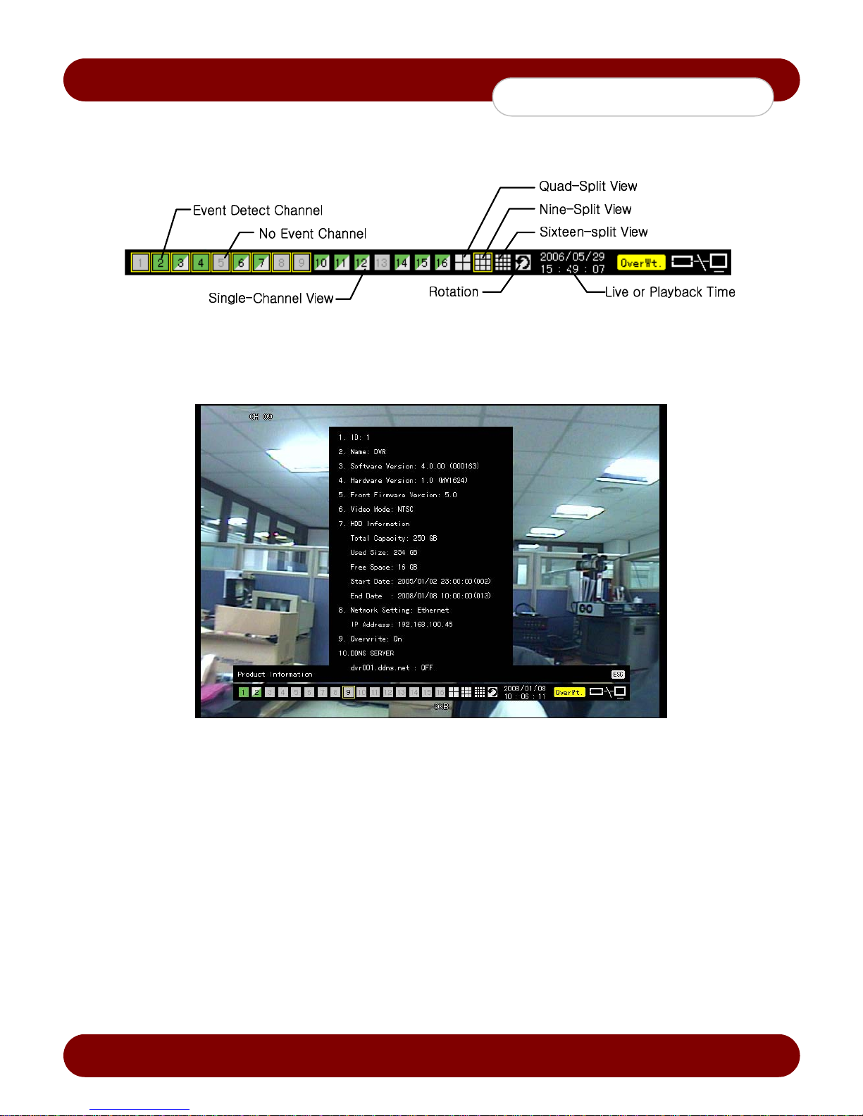
Basic system information is displayed as shown in Figure 4-5.
[Figure 4-5. Recording Status Window]
4-5-1 System Information
1. On the Live mode window, press the {Menu Button} {Status}.
2. Product mode information will be displayed as shown in Figure 4-6.
In order to use remote controller, the product ID needs to be identical. The product ID can be (1~99, 255).
4-5-2 Channel Grouping
1. On the Live mode window, press the {Menu Button} {Channel Grouping}.
2. The user can select the screen in split mode by selecting {Menu} {Display Setting}.
3. On the Live mode window, go to the channel selection window and select the channel to be chang ed by group.
4. On the selection window, select a channel using the arrow keys and press the [Select] button.
Group Setup is not supported for the 1-split mode.
The user can move each channel location in the group by using the mouse.
4-5-3 Adjusting the Screen Brightness
1. On the Live mode window, press the {Menu Button} {Camera/TV Setting} {Brightness}.
2. To adjust the brightness, select a channel on the screen to adjust the brightness by using the arrow keys
3. Activate the channel selection window using the [ESC] button and adjust the brightness of the other channels by
repeating step 2.
Revision A - 16 - © 2008 eSync Manual © eSyn
[Figure 4-6. Product Information Window]
Page 18

c
eSync DVR Manual
System Operation
4-5-4 Adjusting the Screen Contrast
1. On the Live mode window, press the {Menu Button} {Camera/TV Setting} {Contrast}.
2. To adjust the contrast, select a channel on the screen to adjust the contrast by using the arrow keys.
3. Activate the channel selection window using the [ESC] button and adjust the contrast of the other channels by
repeating step 2.
4-5-5 Camera Position Adjustment
1. On the Live mode window, press the {Menu Button} {Camera/TV Setting} {Camera}.
2. To adjust the camera position, select a channel on the screen to adjust the camera position by using the arrow
keys.
3. Activate the channel selection window using the [ESC] button and adjust the camera position of the other
channels by repeating step 2.
Moving the camera positions up, down, right, or left may cause appearance of black or grey areas on the screen.
If the adjustment of the camera if not properly positioned or set in the out-of-range area the black or grey areas will
appear on the screen.
4-5-6 Display Control
1. On the Live mode window, press the {Menu Button} {Camera/TV Setting} {TV Out}.
2. To adjust the display position, select a channel on the screen to adjust the display position by using the arrow
keys.
3. Activate the channel selection window using the [ESC] button and adjust the display position of the other
channels by repeating step 2.
Moving the display positions up, down, right, or left may cause appearance of black or grey areas on the screen.
If the adjustment of the display if not properly positioned or set in the out-of-range area the black or grey areas will
appear on the screen.
4-5-7 Display/Hide Camera Name
1. On the Live mode window, press the {Menu Button} {Display Setting} {Name}(Camera Name).
2. Select the On/Off status using the arrow keys and press the [Select] button.
4-5-8 Adjusting the Screen Border
1. On the Live mode window, press the {Menu Button} {Display Setting} {Border}.
2. Select the desired item using the arrow keys and press the [Select] button.
3. After assigning the setup value per field, press the [ESC] button to exit the Border Line setup mode.
Border setting fields
Field Setup Value Description
Mode setup
Type
Width 2, 4 Set the width of the border.
Color Black, White, Red, Green, Blue Set the color of the border.
On Display the border for each channel screen in varying modes.
Off Hide the border for each channel screen in varying modes.
Internal Hide the external border line.
All Display all border lines.
4-6 Spot Control
1. On the Live mode window, press the {Menu Button} {Control} {Spot}.
2. By default the spot is in sequence mode.
3. To enable the specific channel to be outputted on the SPOT monitor, select a channel then the spot monitoring
setting window will close, and the selected channel screen will be displayed.
4-7 Relay Out
1. On the Live mode window, press the {Menu Button} {Control} {Relay Output}.
2. Selecting a relay channel enables function of the relay.
Revision A - 17 - © 2008 eSync Manual © eSyn
Page 19
c
eSync DVR Manual
System Operation
4-8 Playback
4-8-1 Shifting to Playback Mode
On the Live mode window, press the {Menu Button} {Playback} to shift to Playback mode. The contents will be
played back from the from the previous point where the playback was stopped.
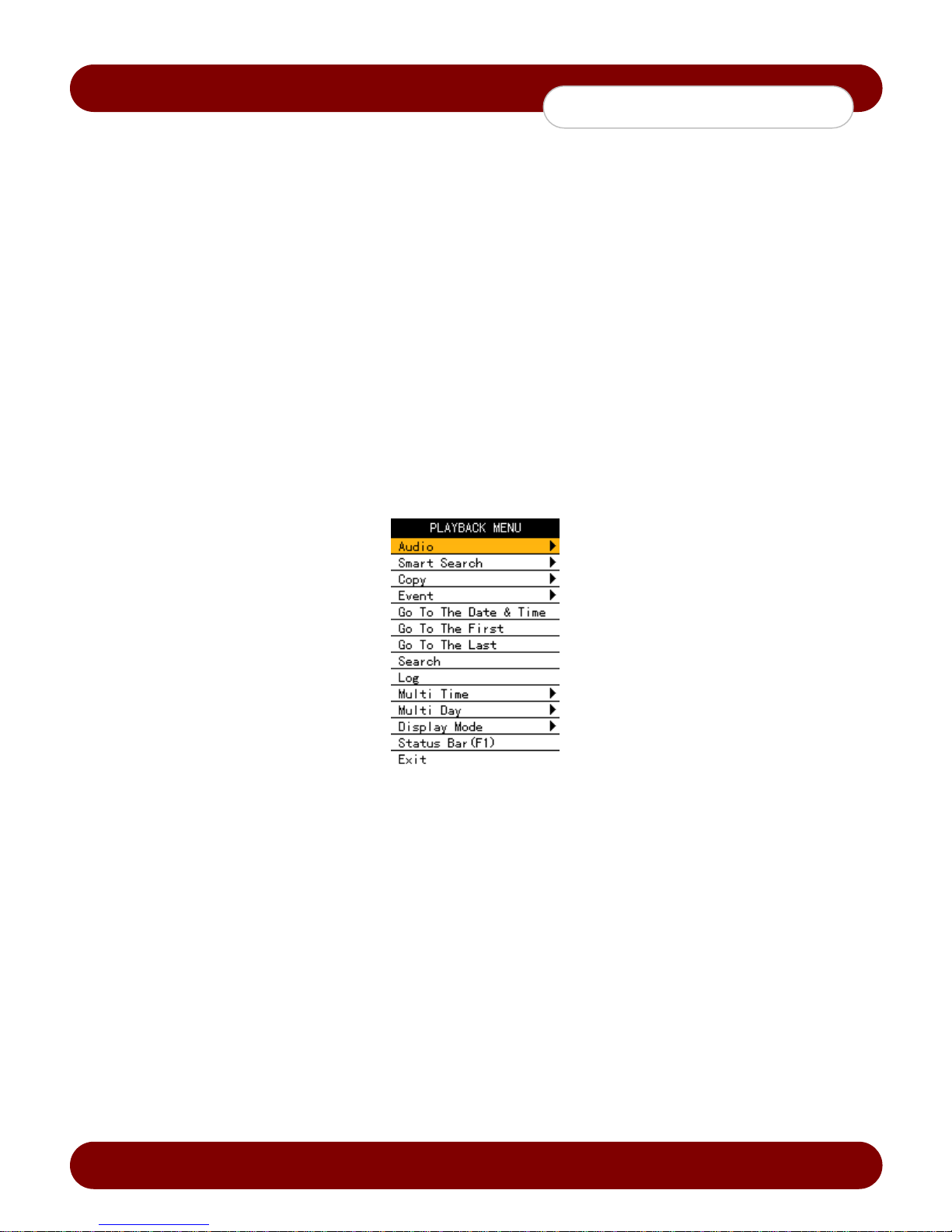
4-8-2 Playback Menu
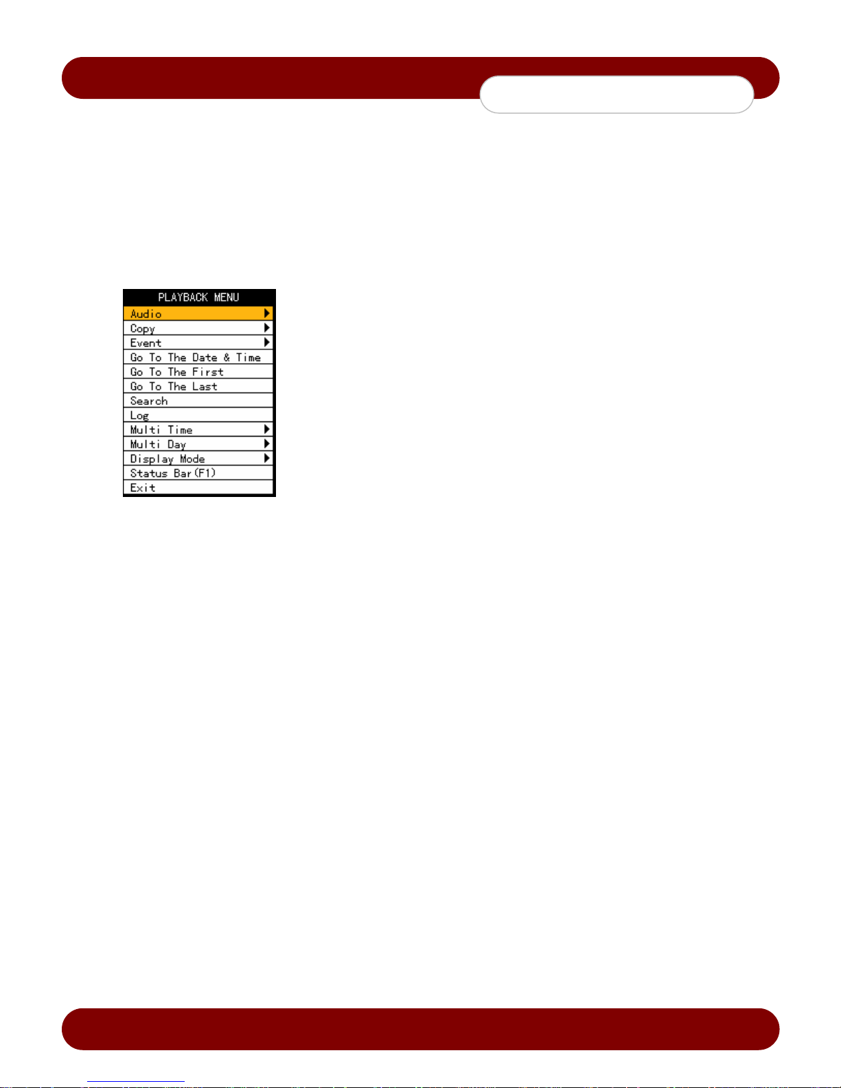
In Playback mode, the user can control all functions using {Playback Menu}.
1. Select or right-click the Menu button. The Playback menu will appear as
shown in Figure 4-7.
2. Select the desired feature using the arrow keys.
3. Press the ESC button or right-click the Menu button to hide the menu.
[Figure 4-7. Playback Menu]
Revision A - 18 - © 2008 eSync Manual © eSyn
Page 20
c
eSync DVR Manual
System Operation
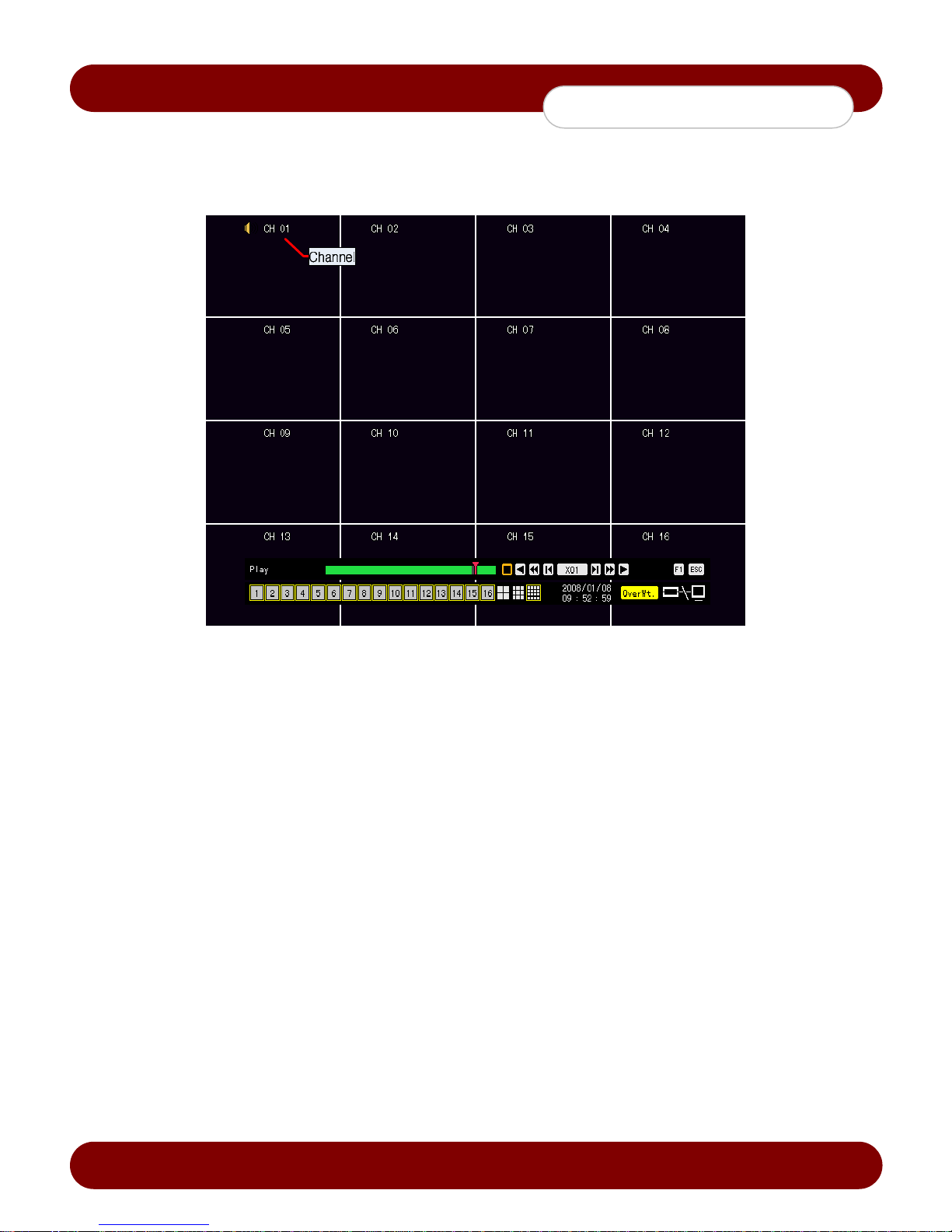
4-8-3 Multi-Channel Search
The user can playback the video contents at a specifc recored time.
In Playback mode, multi-channel playback can be run by selecting {Playback Menu} {Multi-Channel}.
[Figure 4-8. Multi-Channel Playback Screen]
Revision A - 19 - © 2008 eSync Manual © eSyn
Page 21
c
eSync DVR Manual
System Operation
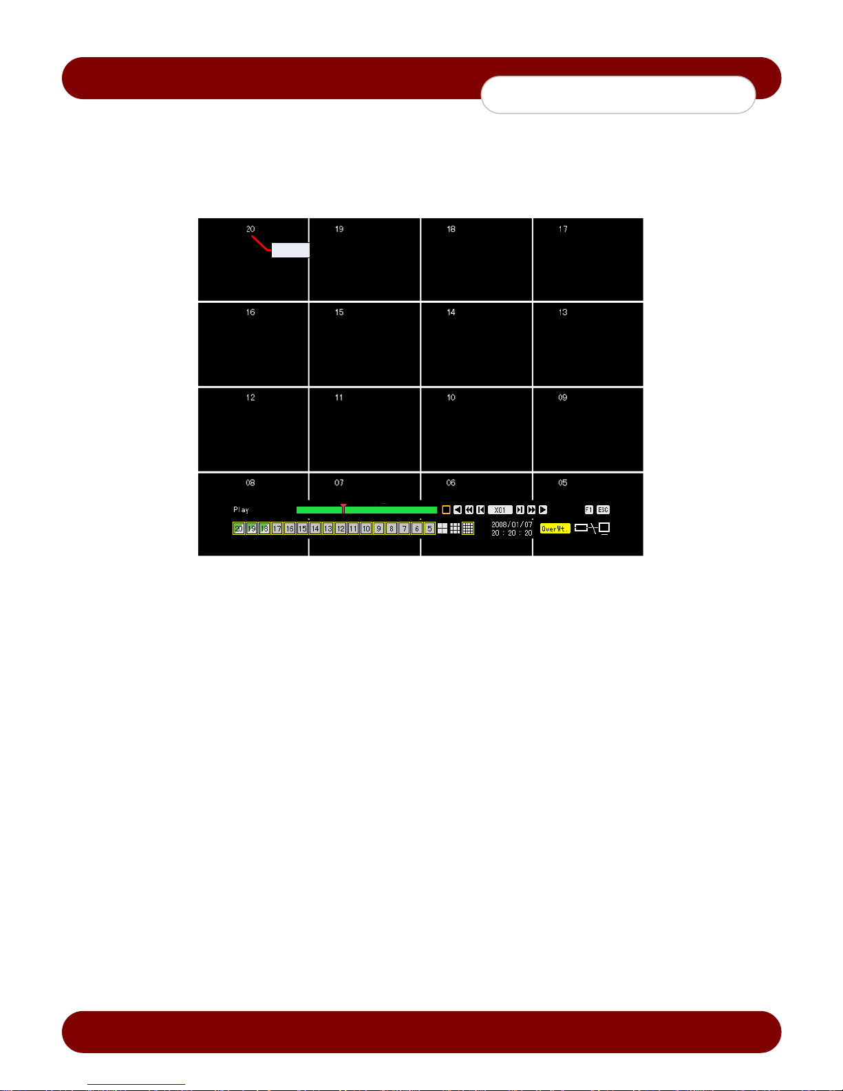
4-8-4 Multi-Time Search
The user can playback the video contents of a certain channel recorded at different times.
The video contents can be sorted by time in descending order.
In Playback mode, select {Playback Menu} {Multi-Time}.
The user can run multi-time playback by selecting a channel using the arrow keys and press the [Select] button.
Time
[Figure 4-9. Multi-Time Playback]
Revision A - 20 - © 2008 eSync Manual © eSyn
Page 22
c
eSync DVR Manual
System Operation
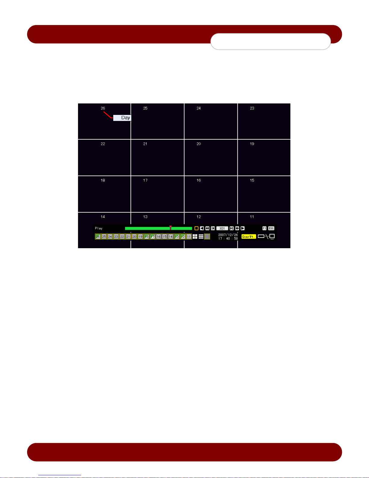
4-8-5 Multi-Day Search
The user can playback the video contents of a certain time recorded on different dates.
The video contents can be sorted by date in descending order.
In Playback mode, select {Playback Menu} {Multi-Day}.
The user can run multi-day playback by selecting a certain channel usin g the arrow keys and press the [Select]
button.
[Figure 4-10. Multi-Day Playback Screen]
Revision A - 21 - © 2008 eSync Manual © eSyn
Page 23
c
eSync DVR Manual
System Operation
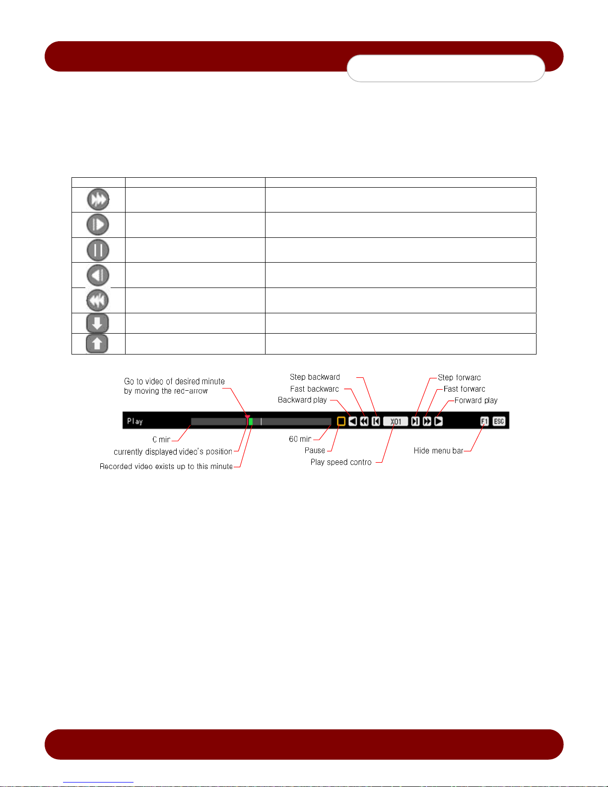
4-8-6 Playback Speed Control
1. In Playback mode, the user can control the playback speed by the functions below.
2. After the selected data is played to the end the status bar, the data of the next hour will be automatically
searched and played.
3. Using the Up/Down button, the user can adjust the playback speed between (x1) through (x29) and fast forward
or rewind at a speed between (x30) through (x300).
Description of the Search Buttons
Button Name Features
Forward playback / Fast forward Playback forward (x1) / Fast forward (x30)
Forward Frame by Frame Frame-by-frame playback
Pause Pause
Reverse frame by frame Reverse playback frame by frame
Reverse playback / Fast reverse Playback in reverse (x1) / Rewind (x30)
Speed Down Decreases the playback speed
Speed Up Increases the playback speed
[Figure 4-11. Playback Status and Control Window]
4-8-7 Playback on a divided screen
1. In Playback mode, the user can split the screen 1/4/9/16 as in the Live mode.
4-8-8 Playback on Audio
1. In Playback mode, select {Playback Menu} {Audio}.
2. Select an audio channel for playback using the arrow keys and press the [Select] button.
4-8-9 Playback on Event
This feature search and plays specific events from the event list.
1. In Playback mode, select {Playback Menu} {Event}.
2. Select an event using the arrow keys and press the [Select] button.
Revision A - 22 - © 2008 eSync Manual © eSyn
Page 24
c
eSync DVR Manual
System Operation
4-8-10 Go To The Date & Time Search
The user can playback the data recorded at a specific time and date.
1. In Playback mode, select {Playback Menu} {Go To The Date & Time}.
2. On the time selection window, set the folder count, time, and channel using the arrow keys and press the Select
button.
3. After confirming the selection, press the OK button. Data will be played starting from the specified time point.
The folder (directory) count is used to select a folder in a different time.
The user can set the channel in Multi-day Playback or Multi-time Playback mode only.
4-8-11 Go To The First Search
1. The user can search and playback the first recorded data.
2. The oldest data will be played back by selecting {Playback Menu} {Go To The First} in Playback mode.
4-8-12 Go To The Last Search
1. The user can search and playback the last recorded data.
2. The latest data will be played back by selecting {Playback Menu} {Go To The Last} in Playback mode.
3. The user can use the Go-To-The-First Search and the Go-To-The-Last Search functions only in {Multi-Channel}
mode.
[Figure 4-12. Playback Menu]
Revision A - 23 - © 2008 eSync Manual © eSyn
Page 25
c
eSync DVR Manual
System Operation
4-9 Log List
The user can search the logs of all system operations such as system power on/off, system setup, network
connection/disconnection, etc.
4-9-1 Log Types
Normal
Recording Event Logs related to recording, e.g., motion detection, sensor detection, and sound detection
Network Logs related to network operations e.g., network login, network logout, and network live
Fail Logs related to system operation failures, e.g., signal loss and network connection failure
All Logs related to all system operations
Logs related to power, file copy/backup failure, setup start/end, playback, and basic system
operations
4-9-2 Viewing the System Log
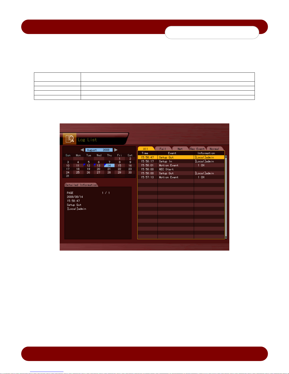
1. Press the {Menu Button} {Log} in real-time Live mode or {Playback Menu} {Log} in Playback mode. The
Log List window will appear as shown in Figure 4-13.
2. On the calendar, Select the desired date (year/month/date) using the arrow keys and press the [Select] button.
3. The user can check the time and the log type (i.e. All / Fail / Net / Rec Event / Normal) using the arrow keys in
the log list.
4. Use the Up/Down button to check the logs by time and type on each page.
5. The user can shift to Playback mode at a certain time for the log list by selecting the Playback button (playback
will start from the time point when logs are saved).
Viewing Time Change-related Log Data
The stored data folder is updated each time the user changes the time. A blue triangular icon is displayed on the date
each time a change is made in the date on the calendar window. Otherwise, a red triangular icon is dis pla yed on the
unchanged date. To view the log details, select the desired date with a red icon. Selecting a date with a blue icon
causes the changed date list to appear.
Revision A - 24 - © 2008 eSync Manual © eSyn
[Figure 4-13. Log List Window]
Page 26
c
eSync DVR Manual
System Operation
4-10 Recording
4-10-1 Recording Types
The eSync series supports various recording types as shown below.
Recording Type Description
Automatic
Continuous DVR will record on continuous mode
Motion DVR will record when motion is activated on the specific channel
Sensor DVR will record when the external sensor port is triggered either by a NO/NC device
Sound DVR will record only when sound is detected
4-10-2 Recording Setup
The user can set the recording type by selecting {Main Setup} {Data Setup}. For more information, see {Main
Setup} {Data Setup} {Recording Setup}.
4-10-3 Viewing the Recording Status
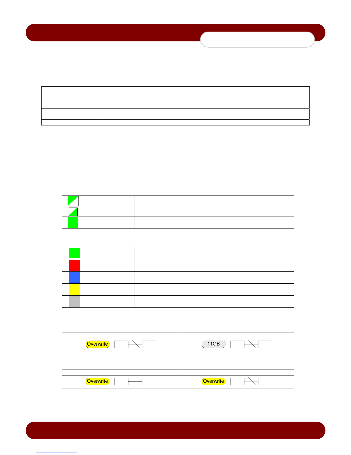
The user can view the recording status, hard disk status, and network connection status of each channel as shown in
Figure 4-3.
• Recording Status by Shape
• Recording Status by Color
• Hard Disk Status
To turn on/off HDD Overwrite, select {Main Setup} {Storage Device}.
Overwrite on Hard Disk Do Not Overwrite on Hard Disk
The user has the option to set two types of recording frame rates: one for normal recording, and one
for event recording (i.e. Motion, Sensor, etc….) when an event is triggered.
Triangle Only video is recorded.
Triangle Only audio is recorded.
Square Both audio and video are recorded.
Green DVR is set to continuous recording mode
Red DVR is set to motion recording mode
Blue DVR is set to sensor recording mode
Yellow DVR is set to sound recording mode
Transparent DVR is not recording.
• Network Access Status
Network Connected Network Disconnected
Revision A - 25 - © 2008 eSync Manual © eSyn
Page 27

c
eSync DVR Manual
System Operation
4-10-4 Starting and Stopping Force Record
In real-time Live mode, the user can enable or disable force recording of all channels by selecting {Live Menu}
{Recording} or pressing the Record button on the keypad.
1) Enable Force Recording on all channels
1. In real-time Live mode, press the {Menu Button} {Recording}.
2. On the login window, enter the password of the local administrator.
3. The force recording of all channels will start based on the previous setting, and the recording status will be
displayed.
2) Disable Force Recording on all channels
1. In real-time Live mode, press the {Menu Button} {Recording}.
2. Enter the password of the local administrator.
3. On the recording stop confirmation window, select the [Yes] button.
4. Any channel recording in progress will stop, and the corresponding status will be displayed on the recording
status window.
Revision A - 26 - © 2008 eSync Manual © eSyn
Page 28
c
eSync DVR Manual
System Operation
4-11 Search
4-11-1 Selecting the Search Mode
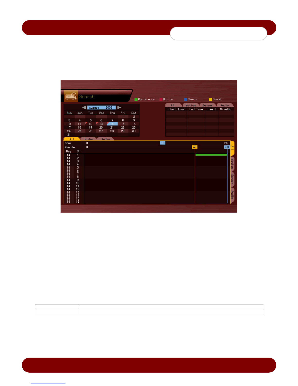
To start the Search window, press the {Menu Button} {Search} in real-time Live mode or {Playback Menu}
{Search} in Playback mode as shown in Figure 4-14.
[Figure 4-14. Search Window]
4-11-2 Selecting the Search Method
The user can run a search using bar graphs (Multi-Channel, Multi-Time, Multi-Day) or file lists (Multi-Channel). One of
these two methods can be used.
4-11-3 Search using the file list
1. Select the desired search date. The one-hour file list for the recorded video will be displayed.
2. Select the desired file using the arrow keys.
Viewing the List of Files with Changed Time
Whenever the user changes the DVR time by selecting {Main Setup} {NTP} {Date and Time}, a new folder
(directory) is created, and the files recorded in the previous channel are displayed in light blue.
In Multi-Channel search mode, the user can run a search using the file list only.
Current Recorded video file based on the current DVR time
Old_Number Recorded video file based on the previous DVR time
Revision A - 27 - © 2008 eSync Manual © eSyn
Page 29

c
eSync DVR Manual
System Operation
4-11-4 Multi-Channel Search
The user can playback the video files of all channels recorded at a specific time.
1. On the calendar window, select the desired date and time using the arrow keys and press the [Select] button.
2. The bar graph on the status bar indicates one hour of the video of each channel.
Green Indicates continuous recording
Red Indicates motion recording
Blue Indicates sensor recording
Yellow Indicates audio recording
Light blue Indicates that recording was done before the DVR time was changed
3. Move the timeline in the status bar to a specific time point by using the arrow keys or the numeric keypad
buttons and press the Search button.
4. Selecting the time shows the recorded video for each channel to be displayed as a bar graph in minutes.
5. Move the time line to a desired time point by using the arrow keys or the numeric buttons and press the [Select]
button. Playback will start from the specified time point.
Viewing the time change via the status bar
1) Files stored in the folder before the time change will be displayed in light blue on the status bar.
2) By selecting a light blue-colored file, the user can view the list of files saved in different folders (before the
time change).
4-11-5 Multi-Time Search
Multi-Time Search enables the user to search up to 16 consecutive hours from a desired time of the day.
1. The user can search data by date as in the Multi-Channel Search mode.
2. Select the date on the calendar, and then it will display hour in the bar graph in descending order.
3. Select the hour, and then it will display the minutes.
4. Select the minutes to review the video files.
5. Click Menu and select Multi-Time Search to choose the specific channel.
4-11-6 Multi-Day Search
Multi-Day Search enables the user search up to 16 consecutive days from a desired day of the month.
1. The user can search data by date as in the Multi-Channel Search mode.
2. Select the date on the calendar, and then it will display hour in the bar graph in descending order.
3. Select the hour, and then it will display the minutes.
4. Select the minutes to review the video files.
5. Click Menu and select Multi-Time Search to choose the specific channel.
Revision A - 28 - © 2008 eSync Manual © eSyn
Page 30
c
eSync DVR Manual
System Operation
4-12 Backup
Backup methods: Built-in DVD-RW, Ethernet, USB2.0 Devices, IEEE1394, DAT, Network Attached Storage.
4-12-1 Backup Method
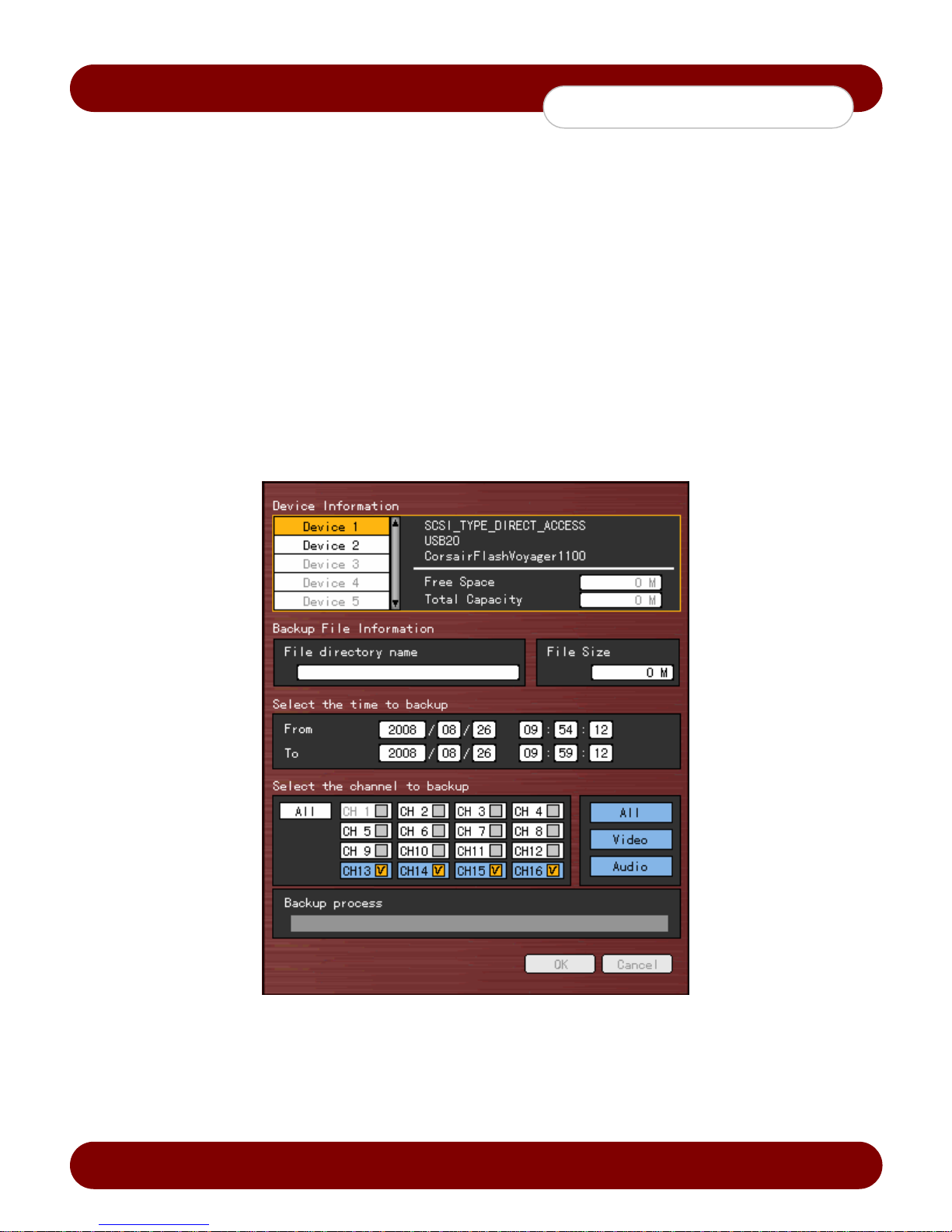
1. In real-time Live mode, press the {Menu Button} {Copy} {Backup}.
The backup menus will appear as sho wn in F igure 4-15. (The default backup time is set to 5 minutes)
2. Choose the backup device from the list and press the [Select] button.
a. If using a CD-R or DVD-R media, please insert the disc first.
b. If using a USB2.0 device, Initialization is required. Go to page 48 for details.
3. It will display the free space of the media selected. (Initilization process might take a few moments depending on
size of the media).
4. Once in the “Time to backup” selection, Press the arrow keys to navigate through year, month, day, hour, minute
and seconds and use the [Select] button to change the values.
5. When the time selection is fini shed, press the down directional button to go to the channels you want to backup.
(Default is all channels. However, only the channels that have data will be available for backup.)
6. Press the OK button to initiate the backup process.
Video files before a [Time Zone Setting] change cannot be backed up.
Revision A - 29 - © 2008 eSync Manual © eSyn
[Figure 4-15. Backup Window]
Page 31

c
eSync DVR Manual
System Operation
4-13 Snapshot
The Snapshot function will create a JPEG formatted screenshot of the video file to USB2.0 device(s) or DVD-R drive.
1. To back up the currently displayed single image, press the {Menu Button} {Copy} {Snapshot}.
a. If using a CD-R or DVD-R media, please insert the disc first.
b. If using a USB2.0 device, Initi alization is required. Go to page 51 for details.
2. When a USB2.0 backup device (excluding DVD-R drive) is search ed, the JPEG file will be stored in the same
device.
3. If there are more than two USB2.0 devices attached to the DVR (excluding DVD-R Drive), a window for selecting
the device will be displayed.
4. If the user wants to backup the snapshot to a DVD-R drive, unplug any USB2.0 devices and make sure there is a
blank media in the DVD-R drive.
4-14 Direct Printing
The direct print function will print out the currently displayed image to any attached printer via USB2.0.
1. To print the displayed image, press the {Menu Button} {Copy} {Print}.
The Print function can be used only with a USB-type Printer supporting the Post Script (PS).
Revision A - 30 - © 2008 eSync Manual © eSyn
Page 32
c
eSync DVR Manual
System Operation
4-15 PTZ Camera Control
4-15-1 Configuring PTZ Features
1. The PTZ camera must be con nected to the system via RS-485 data control cable.
2. To configure the PTZ settings (i.e. Baud Rate, Protocol, ID), go to {Menu Button} {Application Setup}
{PTZ Setup}.
4-15-2 Shifting to PTZ Mode
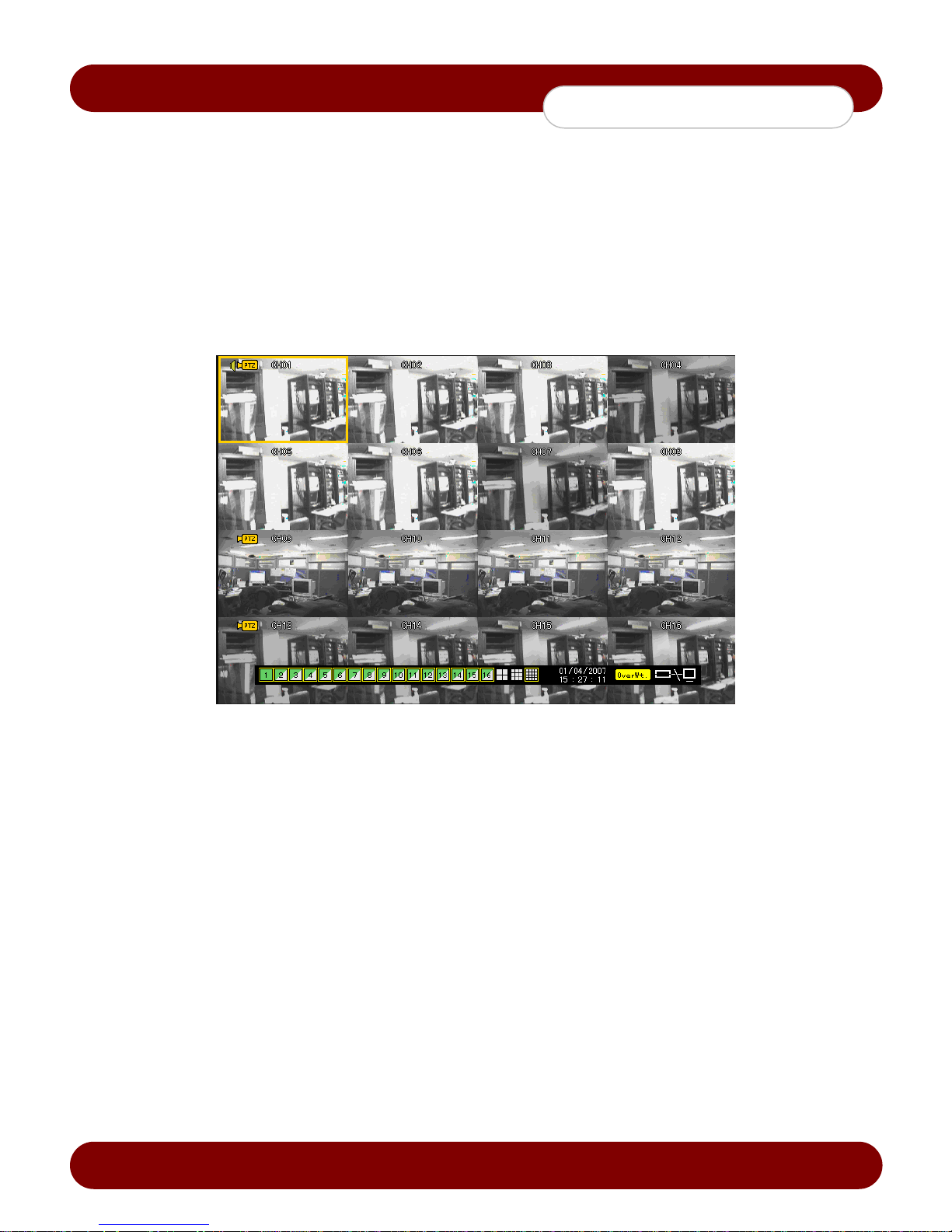
1. To shift to PTZ mode, press the {Menu Button} {PTZ}.
2. As shown in Figure 4-16, an icon will be displayed on the channel with a PTZ camera installed.
[Figure 4-16. Initial Screen in PTZ Mode]
Cha nnel Selection Window
Activation mode The channel selection window can be moved, and the channel screen border is
highlighted in orange.
Selection mode To select the channel, press the [Select] button. The channel is selected, and the channel
screen border is highlighted in blue.
4-15-3 PTZ Control
1) Pan/Tilt
1. Select a PTZ camera using the arrow keys and press the [Select] button.
2. The PTZ control window will appear.
3. Move the PTZ to the desired location using the arrow keys.
4. To shift the screen split mode, select {Menu} {Display Setting} and screen split mode.
2) Zoom
1. To shift to Zoom In/Out mode, press the PTZ button in rotation mode.
2. The user can zoom in or out using the up and down directional arrow keys.
3. To change the screen split in Zoom In/Out mode, select {Menu} {Display Setting} and screen split mode.
3) Focus Control
1. To shift to focus control mode, press the PTZ button again in PT Z Zoom mode.
2. To change focus, use the up and down directional arrow keys.
3. To change the screen split in focus control mode, select {Menu} {Display Setting} and shift to screen
split mode.
Revision A - 31 - © 2008 eSync Manual © eSyn
Page 33

c
eSync DVR Manual
System Operation
4) Preset - To store preset settings of the PTZ camera. The DVR can save up to 8 presets per PTZ camera.
The preset number 9 and 0, are used for Tour mode 1 and 2, respectively as explained below.
1. To shift to Preset mode, press the [Select] button in Pan/Tilt, Zoom, or Focus mode.
2. In PTZ Preset mode, select the Preset mode using the left and right directional keys and the [Select] button.
3. Once the PTZ has been moved to the desired location, press the [Select] button on the preset number to
store the preset.
4. Once the preset has been stored, the number will be displayed in blue.
5) Using the Preset Function
Use the left and right directional arrow buttons to choose the presets, and press the [Select] button to call the
preset.
6) Using the Tour mode
To configure the Tour mode, Select {Application Setup} {PTZ Setup} {Tour}.
1. To set the Tour feature, navigate to the Tour option on the Menu.
2. Press the Tour selection for the desired channel, and press Set.
3. Tour 1 and Tour 2 presets can be saved here.
4. You will be able to define the presets under this window by pressing the [Select] button.
Once you have set the tour mode, Press [ESC] to exit the menu, and go back to the PTZ mode.
5. After the Tour is set, preset 9 and/or preset 0 will be displayed in blue.
6. To activate the tour preset, activate the preset 9 or preset 0 by pressing the [Select] button.
7. To deactivate the Tour feature, press the currently enabled tour presets.
7) Controlling the PTZ Speed
1. Adjust the PTZ speed using the Up/Down button.
2. Speed is set between 1 ~ maximum speed.
3. The maximum speed differs for each PTZ model.
Revision A - 32 - © 2008 eSync Manual © eSyn
Page 34
c
eSync DVR Manual
System Setup
Chapter 5. System Setup
5-1 Main Setup
{Main Setup} is used to set the recording conditions, system settings, storage devices and other major features.
5-1-1 Starting the Main Setup
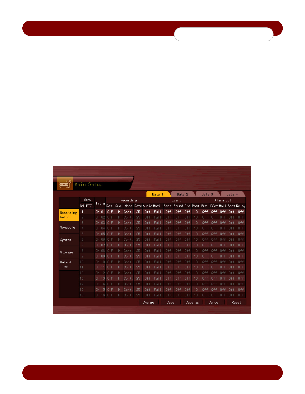
1. On the Live mode window, press the {Menu Button} {Main Setup}.
2. The Main Setup window will appear as shown in Figure 5-1.
5-1-2 Data Selection (Data 1 ~ Data 4)
1. On the Main Setup window, select data using the arrow keys (up to four data types are supported).
5-1-3 Shifting to Recording Setup Mode
{Recording Setup} supports two modes: data mode and channel mode.
On the Recording Setup window, select {Menu} {Convert}. Two modes will be available.
1) Data Mode - This mode is recommended for easiest configuration.
This is a method of setting up the data for all channel numbers based on the data profile of Data 1 - Data 4 as
shown in Figure 5-1.
2) Channel Mode
This is a method of setting up the data for all channel numbers based on four channel groups.
Revision A - 33 - © 2008 eSync Manual © eSyn
[Figure 5-1. Main Setup Window (Data Mode)]
Page 35

c
eSync DVR Manual
System Setup
5-1-4 Saving the Recording Settings
1. To save the new setting, select {Save} using the arro w keys and press the [Select] button.
2. To save a new setting as new data profile, sel ect {Sa ve As}.
3. On the selection window, select the desired data using the arrow keys and press the [Select] button.
4. Exiting without saving changes opens a window asking to save the new settings.
5. Select [Yes] to save the changes.
Once the page has been saved, the settings will be applied immediately.
5-1-5 Recording Setup
1) Camera Channel
1) T itle - To name the camera channel
1. Select {Title} for the camera channel using the arrow keys and press the [Select] button.
2. On the selection window, select the first row and enter the name of the camera channel.
2) Covert - To hide the channel video on the Live mode window
1. Select {Title} for the camera channel using the arrow keys and press the [Select] button.
2. On the selection window, select Covert to hide the camera channel from live view.
3. The video channel will display the eSync Logo with the title “V.C”.
Video data will be saved regardless if the covert option is active.
3) Connection - To enable or disable the activated camera channel manually
1. Select {Title} for the camera channel using the arrow keys and press the [Select] button.
2. On the selection window, select the [Off] disable and [On] to enable the camera channel.
When the camera channel is set to disable, the video contents will not be displ ayed nor recored even if the video
signal is active.
2) Recording - To set the resolution, recording quality, recording type, recording frame, and audio rec ording status
1) Resolutio n – T o set the resolution of the desired channel for recording
1. Select {Recording} {Resolution} for the channel using the arrow keys and press the [Select] button.
2. On the selection window, select the Resolution.
To set all channels at the same time, navigate the arrow keys to go to the top of the {Resolution}
column and press the [Select] button.
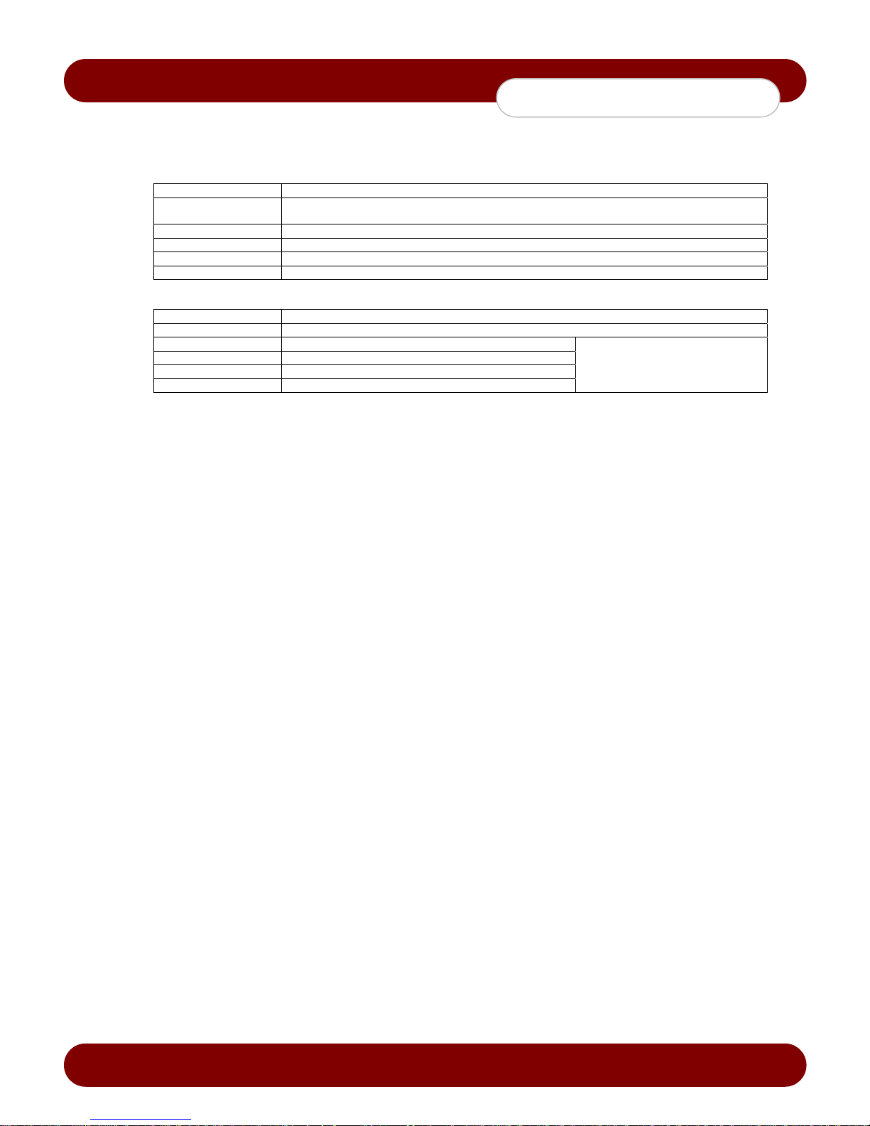
Resolution by Video Type
Resolution Notes NTSC PAL
CIF 1 CIF 352x240 352x288
FIELD HALF D1 = 2 CIF 704x240 704x288
FULL FULL D1 = 4 CIF 704x480 704x576
2) Quality - Set the quality of the recorded video
1. Select {Recording} {Quality} for the channel using the arrow keys and press the [Select] button.
2. On the selection window, select the recording quality.
Recording time varies with the quality setting. Higher the quality, the less recording time.
To set all channels at the same time, navigate the arrow keys to go to the top of the {Quality} on top of
the column and press the [Select] button.
Revision A - 34 - © 2008 eSync Manual © eSyn
Page 36
c
eSync DVR Manual
System Setup
3) Mode - To set the recording type for the channel
1. Select {Recording} {Mode} for the channel using the arrow keys and press the [Sele ct] button.
2. On the selection window, select the recording mode.
To set all channels at the same time, navigate the arrow keys to go to the top of the {Mode} on top of
the column and press the [Select] button.
Recording Type Description
Automatic
Continuous DVR will record on continuous mode
Motion DVR will record when motion is activated on the specific channel
Sensor DVR will record when the external sensor port is triggered either by a NC/NO device
Sound DVR will record only when sound is detected
The user has the option to set two types of recording frame rates: one for normal recording,
and one for event recording (i.e. Motion, Sensor, etc….) when an event is triggered.
Recording Conditions
Recording Type Setting
Automatic Enables setting both Normal and Event simultaneously
Continuous {Record} {Rate}
Motion {Event} {Motion}: Part or All
Sensor {Event} {Sensor}
Sound {Event} {Sound}
{Record}{Rate} Event: 1~30
Revision A - 35 - © 2008 eSync Manual © eSyn
Page 37
c
eSync DVR Manual
System Setup
4) Frame Rate - Depending on the recording mode, the record ing frame can be divided into the Normal type
and Event type.
Normal Sets the recording frame rate for Automatic and Continuous recording
Event Sets the recording frame rate for Automatic, Motion, Sensor, and Sound recording
1. Select {Recording} {Rate} for the channel using the arrow keys and press the [Select] button.
2. On the selection window, select the frame rate.
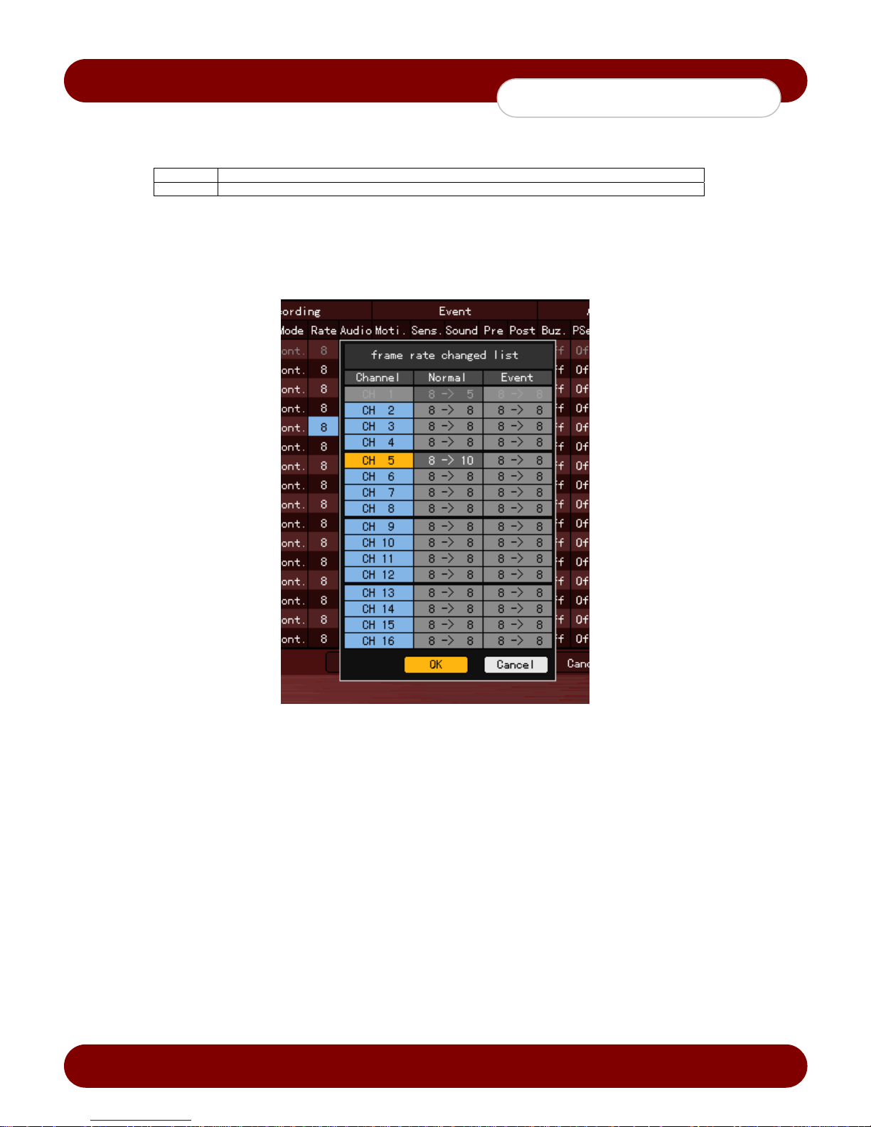
3. If the users adjusts a frame rate on a channel that is higher than the maximum frame rate, the DVR will
prompt a menu to adjust the other channels.
4. The yellow-colored channel is currently being set as shown in Figure 5- 3.
[Figure 5-3. Frame Rate Setting Window]
To set all channels at the same time, navigate the arrow keys to go to the top of the {Rate} on top of
the column and press the [Select] button.
5) Audio - To set the recording for the audio channel
1. Select {Recording} {Audio} for the channel using the arrow keys and press the [Select] button.
2. On the selection window, select whether to record audio or not.
To set all channels at the same time, navigate the arrow keys to go to the top of the {Audio} on
top of the column and press the [Select] button.
Revision A - 36 - © 2008 eSync Manual © eSyn
Page 38

c
eSync DVR Manual
System Setup
1) Event
1) Motion - T his function enables the DVR to record when there is motion on the video channel to trigger
recording. The default value is [Off].
◊ Full
Detects all motion of the image in each channel will trigger recording.
1. Select {Event} {Motion} for the channel using the arrow keys and press the [Select] button.
2. On the selection window, select All.
◊ Partial
Motion detection in the us er-defined areas on the grid only will trigger recording.
1. Select {Event} {Motion} for the channel using the arrow keys and press the [Select] button.
2. On the selection window, select Partial.
3. The grid will be displayed on the screen.
4. Select the area where motion will be detected using the arrow keys and press the [Select] button.
5. Select the zone and press the [ESC] button.
◊ Off
Motion detection in the video is disabled.
◊ Select the motion detection sensitivity
1. Select {Event} {Motion} {Sensitivity} for the channel using the arrow keys and press the Menu
button.
2. On the selection window, select the sensitivity using the arrow keys and press the [Select] button.
To set all channels at the same time, navigate the arrow keys to go to the top of the {Motion} on
top of the column and press the [Select] button.
2) Sensor - T o set the detection of input triggered by external sensors. Up to 4/8/16 external sensors can be
set. When a signal of an external sensor is detected, the camera channel assigned to the sensor will start
recording.
1. Select {Event} {Sensor} for the channel using the arrow keys and press the [Select] button.
2. On the selection window, select an external sensor channel using the arrow keys and press the Select
button.
3. Select {Event} {Sensor} {Sensor Type} for the channel using the arrow keys and press the Menu
button.
On the selection window, select the sensor type using the arrow keys and press the [Select] button.
To set all channels at the same time, navigate the arrow keys to go to the top of the {Sensor} on
top of the column and press the [Select] button.
Normal Close (NC): Normally closed; opens when a signal is received
Normal Open (NO): Normally open; closes when a signal is received
Revision A - 37 - © 2008 eSync Manual © eSyn
Page 39

c
eSync DVR Manual
System Setup
3) Sound - To set the detection of input triggered by external microphone. Up to 4/8/16 external microphones
can be set. When a sound from the external microphone is detected, the camera channel assigned to the
microphone will start recording.
1. Select {Event} {Sound} for the channel using the arrow keys and press the [Select] button.
2. On the selection window, select an audio channel using the arrow keys and press the [Select] button.
3. Select {Event} {Sound} {Sensitivity} for the channel using the arrow keys and press the Menu
button.
4. On the selection window, select audio sensitivity using the arrow keys and press the [Select] button.
To set all channels at the same time, navigate the arrow keys to go to the top of the {Sound} on
top of the column and press the [Select] button.
4) Post Alarm - To set the recording time after the occurrence of an event
Occurrence of an event
PostPre
5 ~ 300 Sec
1. Select {Event} {Post} for the channel using the arrow keys and press the [Select] button.
2. On the selection window, select the time value 5 ~ 300 seconds by using the arrow keys and press the
[Select] button.
Time is set in seconds. Whenever an event is detected, recording will be done for the set time.
To set all channels at the same time, navigate the arrow keys to go to the top of the {POST} on
top of the column and press the [Select] button.
Revision A - 38 - © 2008 eSync Manual © eSyn
Page 40
c
eSync DVR Manual
System Setup
4) Alarm Out - This feature is allows to generate alarms through the buzzer, email notification, spot monitor, or
relay in case of an alarm event.
1) Buzzer - T his feature is used to run the internal buzzer in the DVR in case of an event.
1. Select {Alarm Out} {Buzzer} for the channel using the arrow keys and press the [Select] button.
2. On the selection window, select the event subject to buzzer operation (e.g., motion, sensor, sound)
using the arrow keys and press the [Select] button to activate or deactivate the buzzer.
2) Preset - When an eve nt occurs, the PTZ camera will move to an assigned preset.
1. Select {Alarm Out} {Preset} for the channel using the arrow keys and press the [Select] button.
2. On the selection window, select the event (sensor or sound) to activate an alarm or not by using the
arrow keys and press the [Select] button.
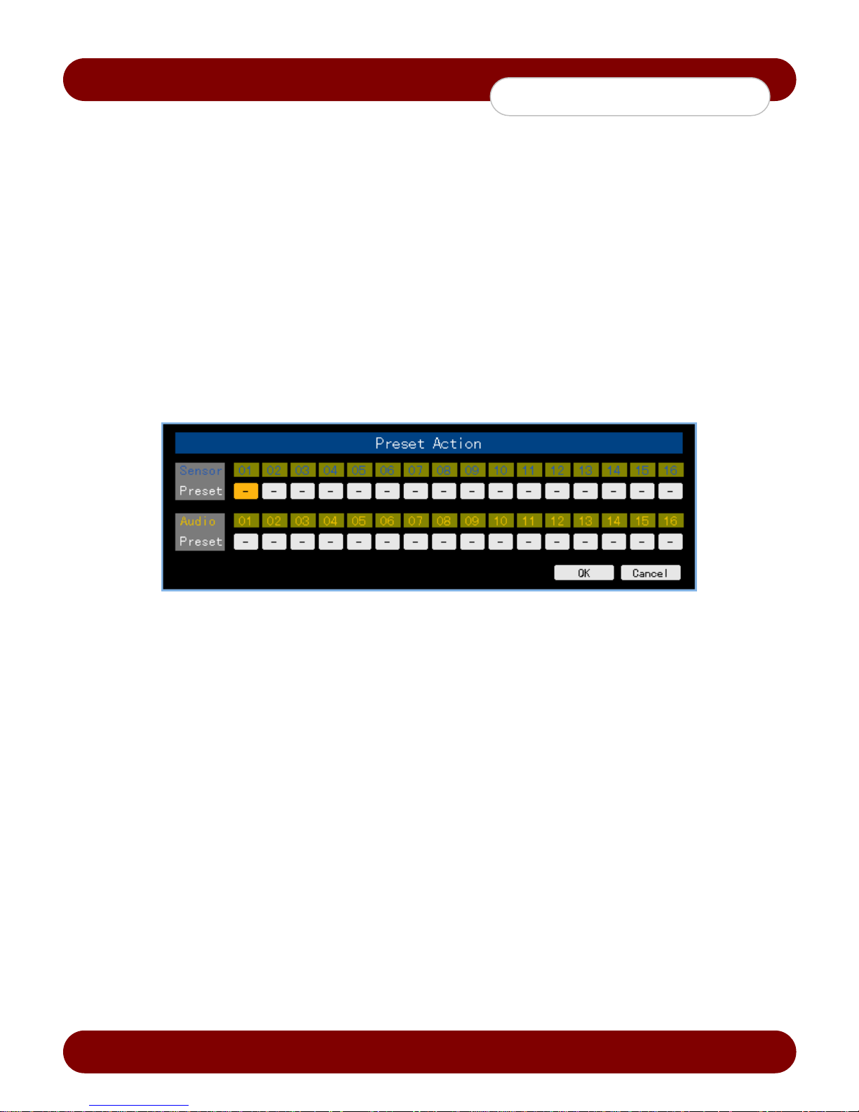
3. Select {Alarm Out} {Preset} {Preset Action} for the channel using the arrow keys and press the
Menu button.
4. Assign a Preset for each event.
5. Select the OK button to save. Otherwise, select the cancel button and press the [SELECT] button to
cancel.
To set all channels at the same time, navigate the arrow keys to go to the top of the {Preset} column and
press the [Select] button.
Preset can be set from 1-8
3) Email notificati on - W hen an alarm or an event occurs, emails will be sent to the specified email address.
1. Select {Alarm Out} {Mail} for the channel using the arrow keys and press the [Select] button.
2. On the selection window, select event types to activate the email notification by usng the arrow keys
and press the [Select] button.
The email notification can be set up in the {Application Setup} {Network} {Alarm} menu.
4) Spot - Displays the video on the TV monitor connected to the spot out on the rear side of the DVR during an
alarm event.
1. Select {Alarm Out} {Spot} for the channel using the arrow keys and press the [Select] button.
2. On the selection windo w, select the event t ype to activate the spot function by using the arrow keys and
press the [Select] button.
To set all channels at the same time, navigate the arrow keys to go to the top of the {Spot} column and
press the [Select] button.
[Figure 5-4. Preset Action Setting Window]
Revision A - 39 - © 2008 eSync Manual © eSyn
Page 41
c
eSync DVR Manual
System Setup
5) Relay - If an alarm or event occurs, any or all external alarm devices connected to the assigned relay port
will be activated.
1. Select {Alarm Out} {Relay} for the channel using the arrow keys and press the [Select] button.
2. On the selection windo w, select the event type to activate the Relay function by using the arrow
keys and press the [Select] button.
3. Select {Alarm Out} {Relay} {Relay Type} for the channel using the arrow keys and press the Menu
button.
4. On the selection window, select the relay type using the arrow keys and press the [Select] button.
To set all channels at the same time, navigate the arrow keys to go to the top of the {Relay} colum n and
press the [Select] button.
5-1-6 Recording Schedule
{Recording Schedule} is used to save the system configuration as data from Data 1 to Data 4 and to ma ke a reco rd ing
based on the system configuration for each day/time.
1) Selecting the Recording Schedule Menu
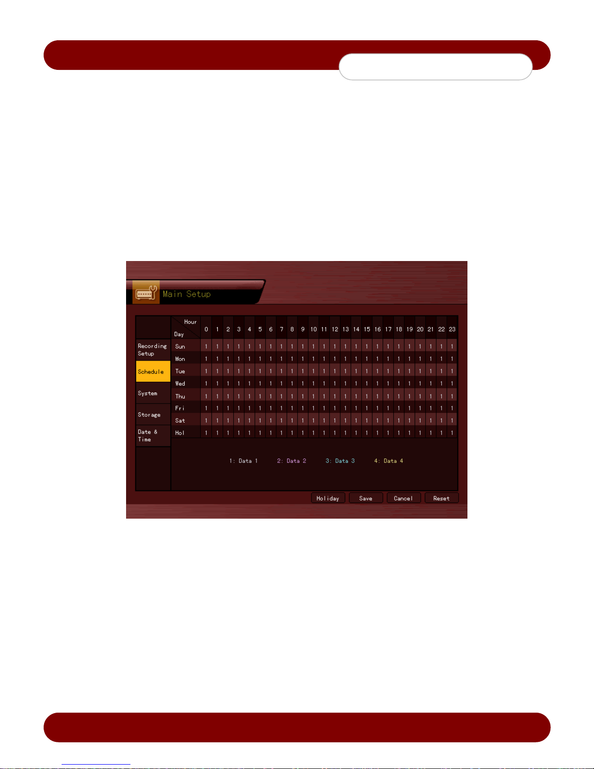
On the initial Main Setup screen shown in Figure 5-1, the user can select a recording schedule using the arrow
keys and the [Select] button.
The initial recording schedule screen will app ear as shown in Figure 5-5.
2) Recording Schedule Setting
1) To set each column
1. Navigate to the time and dat e using the directional arrow keys.
2. Presss the [Select] button to change the data profile number.
2) To set the entire column
1. Navigate to the top with the hours with directi onal arrow keys.
2. Press the [Select] button to change the data profil e number.
Revision A - 40 - © 2008 eSync Manual © eSyn
[Figure 5-5. Recording Schedule Window]
Page 42
c
eSync DVR Manual
System Setup
3) To set holidays
This feature is used to enab le the user to set the holidays to disable recording.
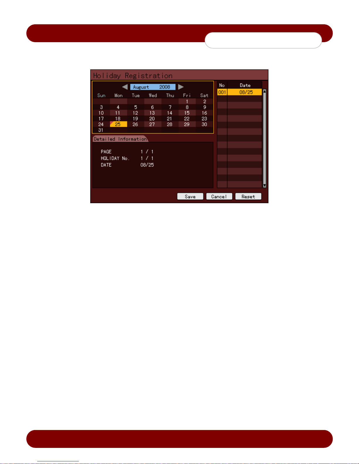
[Figure 5-6. Holiday Registration Window]
If the date for the holiday and day of the week are the same in the {Recording Schedule} menu, the
holiday setup will have higher priority.
A. Calendar
The defined holidays will be indicated with a red triangle.
B. Holiday List
The list of all defined holidays will be disp layed.
A total of 15 holidays will be displayed per page, and the rest will be displayed on the following
page(s) if more than 15.
C. Holiday Information
Detailed information for the selected date will be disp layed.
{Page}: shows the page count when there are more than 15 holidays
. {Current page/Total page}
{Holiday No.}: denotes the holiday number arranged by date
{Number of selected holidays/Total number of holidays}
{Date}: shows the date of the holiday
1. Click the {Recording Schedule} menu and select {Menu} {Holiday}.
2. On the Holiday Registration window, select the date by using the arrow button
and press the [Select] button.
3. After setting the hol iday, press the [ESC] button followed by the [Save] button at the bottom of the
menu. Afterward, press the [Select] button.
Revision A - 41 - © 2008 eSync Manual © eSyn
Page 43

c
eSync DVR Manual
System Setup
5-1-7 System
The system settings of the DVR can be configured under {System}.
1. {Local Administrator’s Password}
2. {Menu Time Out}
3. {DVR Name}
4. {Remote Controller ID}
5. {Date Display Type}
6. {Users}
7. {Alarm Action}
8. {Set Alarm Duration}
9. {Upgrade}
10. {Factory Setup}
11. {PTZ Home Position Time}
12. {PTZ Control Type}
13. {Language}
14. {RS232C Port}
15. {System Controller ID}
To set the password of the Local Administrator
To set the automatic menu time out for the system
To name the DVR device. Default is eSync
To name the remote controller for running the system
To set the date display format
To register, add, modify or delete users
To turn the System Buzzer ON/OFF
To set the alarm generation time (in seconds)
Upgrades the system value setup or firmware
To default system setup to factory settings
Automatically runs to Preset No. 1 of PTZ
PTZ control method setting
System language setting
Use of the RS232C port
Unique system controller number setting
Revision A - 42 - © 2008 eSync Manual © eSyn
Page 44
c
eSync DVR Manual
System Setup
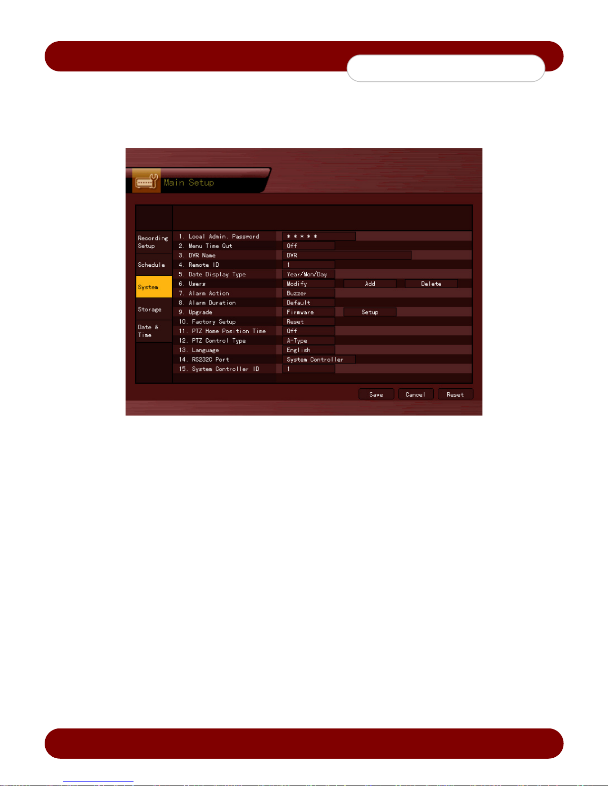
Selecting the system menu
1. On the initial Main Setup window shown in Figure 5-1, select the system by using the arrow keys and press
the [Select] button.
2. The system configuration menu will appear as shown in Figure 5-7.
[Figure 5-7. System Setup Window]
1) {Local Administrator’s Password}
1. Select {Local Administrator’s Password} by using the arrow keys and press the [Select] button.
2. On the password input window, enter a password using the numeric buttons of the remote controller or the
DVR and press the [Select] button (the password can contain up to five digits).
2) {Menu Time Out}
1. If no input is made in the System Setup menu using the front buttons, remote controller, or mouse, the
system automatically logs out to Live mode.
2. Select {Menu Time Out} using the arrow keys and press the [Select] button.
3. On the selection window, select the timeout you want to set by using the arrow keys and press the [Select]
button.
OFF
Automatic Menu Exit is not used. The user can exit the menu by only pressing the [ESC] button in the System
menu.
1 MIN / 2 MIN / 3 MIN / Custom - up to 99 MIN
If there is no input using the front button, remote controller, or mouse, the DVR will logout to the Live mode.
3) {DVR Name}
1. To change the DVR name, select {DVR Name} by using the arrow keys and press the [Select] button.
2. On the input window, enter a name using the numeric buttons or the arrow keys and press the [Select]
button (the system name may contain up to 20 English characters).
Revision A - 43 - © 2008 eSync Manual © eSyn
Page 45
c
eSync DVR Manual
System Setup
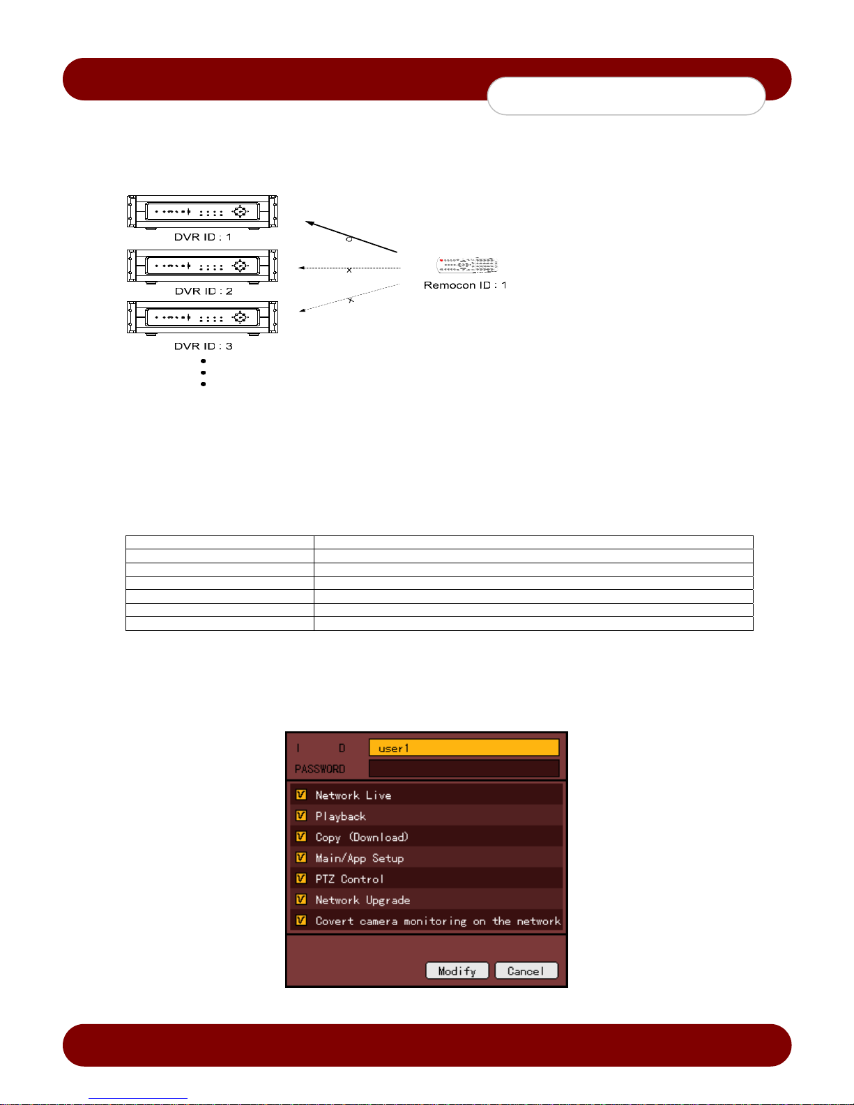
4) Remote Controller ID - When multiple devices are used set the remote controller ID to identify input signals
from a remote controller.
DVR and the remote must have the same ID to work properly
1. Select {remote controller ID} using the arrow keys and press the [Select] bu tton.
2. Enter the ID (between 0 and 99) using the numeric buttons or the arrow keys and press the [Select] button.
If you forgot the DVR ID, set the remote controller ID to 999 to start the DVR.
Note, however, the DVR ID should be the same as the remote controller ID.
5) {Date Display Type} - Choose from Y/M/D, D/M/Y, M/D/Y
6) {Users} - Adds, modify, or deletes the user levels
Network Live Enable live vieweing via network
Playback Enable playback via local and network
Copy (Download) Enable copying and downloading files from DVR via local and network
PTZ Control Enable PTZ camera control via local and network
Main/Application Setup Enable Local Administrator Privileges via local and network
Network Upgrade Enable Remote firmware upgrade via local and network
View Hidden Channels on Network Enables viewing hidden channels via network
A) Edit User Information
1. Select {Register User} {Edit User} using the arrow keys and press the [Select] button.
2. On the selection window, select a user using the arrow keys and press the [Select] button.
3. On the user level setting window, set the user level by using the arrow keys and press the [Select]
button as shown in Figure 5-8.
Revision A - 44 - © 2008 eSync Manual © eSyn
[Figure 5-8. User level Setup Window]
Page 46

c
eSync DVR Manual
System Setup
B) Add User
1. Select {Register User} {Add User} by using the arrow keys and press the [Select] button.
2. On the user registration window, enter the ID and the password. Up to four users levels can be
registered (the user ID and password may contain up to 30 English characters).
3. After entering the user ID and password, select the user level by using the arrow keys and press the
[Select] button.
C) Delete User
1. Select {Register User} {Delete User} by using the arrow keys and press the [Select] button.
2. On the selection windo w, select the user to delete by usin g the arrow keys and press the [Select]
button.
7) {Alarm Action} – Default Action is [Buzzer]
1. Select {Alarm Action} using the arrow keys and press the [Select] button.
2. On the selection window, select [Off] to disable the Action or select [Buzzer], [Email], and/or [Relay] by
pressing the arrow keys and press the [Select] button.
The {Alarm Action} function starts the buzzer in case of HDD Fail, Backup Fail, Network Fail, and Fan Fail,
Power Fail, or Signal loss. When the buzzer is off, the DVR will only prompt the action on the screen.
8) {Alarm Duration}
1. Select {Alarm Duration} by using the arrow keys and press the [Select] button.
2. On the selection window, select the time for generating the alarm using the arrow keys and press the [Select]
button.
9) {Upgrade} - The DVR can be upgraded through an external USB 2.0 storage device.
The user will need to need set the USB2.0 as a Backup-Init storage device, Please refer to 48.
1. Copy the upgrade file to the root folder in the external USB 2.0 storage device.
A) When copying an upgrade file from the PC, safely remove the USB device from the PC and
disconnect it from the USB port.
B) If the USB device is disconnected from the USB port while the upgrade file is being copied, the
DVR system may not automatically detect the file.
2. Connect the storage device with the upgrade file into the US B 2.0 port in th e front of the DVR.
3. Select {Upgrade} using the arrow keys and press the [Select] button.
4. After selecting the file to be upgraded, press the [Select] button.
Downgrading to a previous version is not supported.
The upgrade information windo w will appear within 15 seconds.
Read the information and select [Yes] to start the upgrade. Select [No] to return to the {System} window.
5. After the update is completed, the system will reboot.
6. To view the current firmware version, press the {Status} button on the front panel of the DVR or select the
{Status} {Product Information} {Software Version}.
10) {Factory Setup}
1. Select {Reset} using the arrow keys and press the [Select] button.
2. When prompted whether to reset all setting, select [Yes].
The factory setup will restore all the settings to Factory Default, excluding any Firm ware updates.
Revision A - 45 - © 2008 eSync Manual © eSyn
Page 47

c
eSync DVR Manual
System Setup
11) {PTZ Home Position Time}
This feature enables Preset 1 to automatically run for the assigned PTZ if no control occurs for a specific time
period after using the PTZ functions. Preset 1 replaces the Home Position of the PTZ .
1. Select {PTZ Home Position Time} using the arrow keys and press the [Select] button.
2. On the selection window, select the time using the arrow keys and press the [Select] button.
12) {PTZ Control Type}
Select {PTZ Control Type} by using the arrow keys and press the [Select] button.
On the selection window, select the type using the arrow keys and press the [Select] button.
A-Type
When the directional arrow key is pressed, in the PTZ mode, the DVR will lock the PTZ movement until the key is
pressed again. There is almost no delay when using this type.
B-Type
When the directional arrow key is pressed, in the PTZ mode, the DVR will move the PTZ in 1 second increments.
There is a 0.5 second delay when using this type.
13) {Language}
To select the language for the On Screen Display (OSD) menu of the system.
1. Select {Language} using the arrow keys and press the [Select] button.
2. On the selection window, select the language using the arrow keys and press the [Select] button.
14) {RS232C Port}
1. Select {RS232C Port} using the arrow keys and press the [Select] button.
2. On the selection window, select the device using the arrow keys and pr ess the [Select] button.
(i.e. Storage, System Controller, GPS Time Server, Console)
15) {System Controller ID}
1. Select {System Controller ID} using the arrow keys and press the [Select] button.
2. On the input window, enter the ID (between 1 and 255) using the numeric buttons or arrow keys and press
the [Select] button.
Save
1. After changing the setting in the {System} menu, save the changes.
2. After completing the system setting, select {Menu} {Save}.
Revision A - 46 - © 2008 eSync Manual © eSyn
Page 48
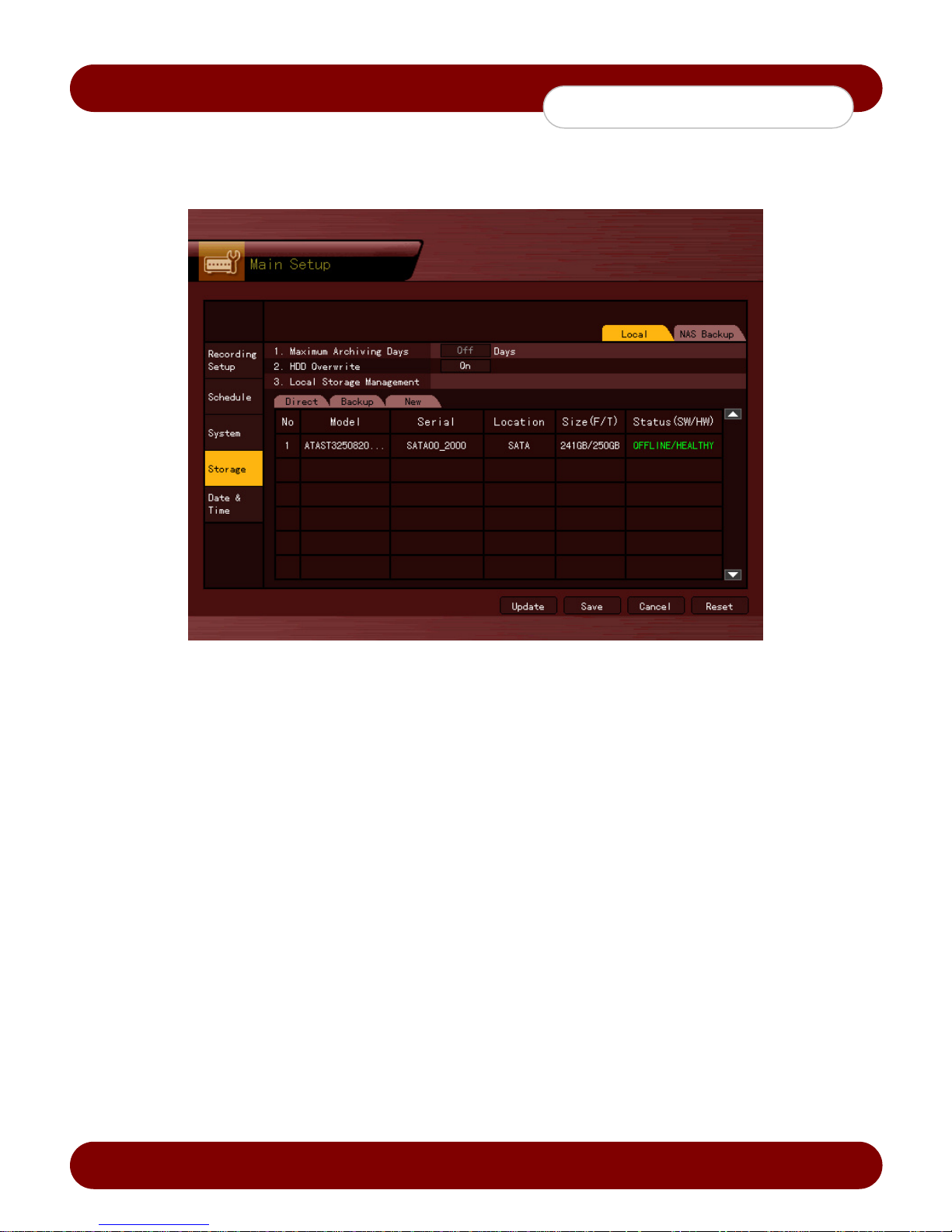
c
eSync DVR Manual
System Setup
5-1-8 Storage
1) Selecting the Storage Menu
1. Select {Main Setup} {Storage}.
[Figure 5-9. Storage Window (Local)]
2) Local
A) Selecting the Local Men u
1. Select {Storage} {Local}.
To apply the new setting, save the new setting.
Reload: Used to read the local storage device manageme nt information again
Save: Saves the setting data
Cancel: Exits without saving the setting
Reset: Deletes the previous settings and initializes the setup
B) HDD Overwrite - This feature is used to overwrite on the HDD.
1. Select {HDD Overwrite} using the arrow keys and press the [Select] button.
2. On the input windo w, select whether to use this function or not using the arrow keys and press the
[Select] button.
ON
If there is no more hard disk space left, the existing files will be overwritten starting with the oldest.
OFF
If the hard disk space has been used up, the DVR will stop recording.
C) Selecting the Manage Local Storage Menu
1. Select {Local Storage Management} using the arrow keys and press the [Select] button.
2. Local storage typ es include {Direct}, {Backup}, and {New}.
Revision A - 47 - © 2008 eSync Manual © eSyn
Page 49
c
eSync DVR Manual
System Setup
D) Maintenance o f th e local storage device
A local storage device refers to any storage device(s) connected to the eSync DVR, such as the internal
hard disk drive(s), USB2.0 device(s), and other device(s) connected to the IEEE1394 port. Local storage
types include {New}, {Direct}, and {Backup}. The functions are as follows:
New: The administrator can manage all initially detected storages. All initially detected storages are
displayed as New and can be changed into Storage or Backup.
{Direct Initialize}: Changes the selected storage into a dedicated direct storage
{Backup Initialize}: Changes the selected storage into a backup storage
{New} At least one storag e device needs to be selected as a dedicated storage.
Otherwise, the data cannot be stored in real time.
Direct: The administrator can manage direct storages. A direct storage stores data on the hard disk in
real time. Five commands can be initiated on the storage devices. Depending on the S/W status,
however, some commands cannot be initiated.
{New}: Returns the status of the selected storage device to New; if this command is,
the selected storage device will be m o ved to the {New} storage device manager
{Online}: Changes the selected storage device in online state
{Offline}: Changes the selected storage device in offline state
{Format}: Formats the selected storage
{Eject}: Separates the selected device completely from the software
Physical states supporting the execution of the commands above include Healthy and Warning. In the
fault state, however, no command can be initiated.
When removing a device installed in the DVR, USB, or storage connected to the IEEE1394
port, the user shall run the {Eject} command
Backup
The administrator can mana ge backup storages. Backup storages are permitted for data backup, not used
for current recording files. The user can run only the {New} command.
Depending on the storage type, the storage can be used only for either direct or backup.
E) Configuration of the local storage device
1. {Model}: Model name of the storage device
2. {Serial}: Serial number of the storage device (May not be compatiable with some devices)
3. {Location}: Physical location of the storage device
4. {Capacity (T/F)}: Storage device capacity (T: Total; F: Free)
5. {Status (SW/HW)}: Storage device status (SW: Software; HW: Hardware)
There are three software status types:
Active: Connected to DVR and currently saving the data
Online: Only connected to storage or backup device
Offline: Not connected to storage or backup device
There are three hardware status types:
Healthy: Connected to storage or backup device; functions normally
Warning: Connected to storage or backup device, but error was detected
(for more information, see the descri ption below).
Fault: Not connected to storage or backup device; cannot perform data saving or backup
Revision A - 48 - © 2008 eSync Manual © eSyn
Page 50
c
eSync DVR Manual
System Setup
Fault state: The storage device is completely damaged, and none of the S/W operations can be
performed. The fault state is not related to a DVR problem. The DVR has detected the fault and stopped
the recording.
Warning state: The storage device has a physical error that will be notified by the DVR. Backing
up data in the corresponding storage device and replacing the defective device with a new device is
strongly recommended.
If there is an active storage device with a warning or a fault, a message is displayed on the upper left
part of the screen. To clear the warning message, the user will need to check the {Log} on the DVR.
F) Operation after adding a local storage device
1. Connect power to the s ystem and boot the system.
2. Select {Main Setup} {Storage} {Local} using the arrow keys and press the [Select] button.
3. A newly displayed disk will be displayed as {New}.
4. Select a newly installed disk using the arrow keys and press the [Select] button and initialize the disk as
a {Direct} or a {Backup} disk. The following describes the method of setting a direct storage:
Selecting {Direct-Init} or {Backup-Init} may cause all data in the device to be erased.
While {Direct-Init} or {Backup-Init} is in progress, do not remove the device as it
may cause an error when detecting the device.
To use the external or portable storage device for system upgrade, set to {Backup-
Init} in the {New} item for {Main Setup} {Storage Device} {Local Storage Device
Management}.
When using USB2.0 storage device for the first time, a backup USB device will be
detected in the {New} category. Therefore, a USB device in the {New} category
must be set up as {Backup-Init} prior to use for backup. A USB device that has
already been initialized as {Backup} will not need to be configured again.
5. {Direct} shows the status of the newly installed disk online.
G) Operation of the local storage device
1. From the {Manage Local Storage} menu, select {Direct}, {Backup}, and {New} using the arrow keys.
2. If there is a valid storage device in the corresponding tab, the storage device may be selected by using
the directional arrow buttons.
3. Select the storage by usin g the [Select] button. Popup menu will be displayed (Direct-Init / Backup-Init)
4. Select menus using the arrow keys and press the [Select] button.
Revision A - 49 - © 2008 eSync Manual © eSyn
Page 51
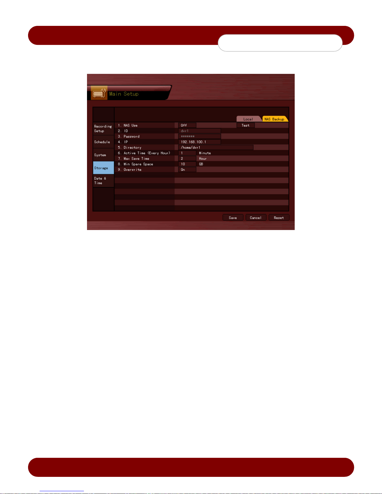
c
eSync DVR Manual
System Setup
3) NAS Backup
1) Selecting the NAS Backup Menu
1. Select {Main Setup} {Storage} {NAS Backup}.
[Figure 5-10. Storage Window (NAS Backup)]
2) Using NAS
1. Select {NAS Use} using the arrow keys and press the [Select] button.
2. On the selection window, select whether to use NAS or not using the arrow keys and press the [Select]
button.
3) ID and Password - ID and passwords are fixed values (cannot be modified).
4) IP
1. Select {IP} using the arrow keys and press the [Select] button.
2. On the input windo w, enter the IP using the arrow keys and press the [Select] button.
5) Directory
1. Select {Directory} using the arrow keys and press the [Select] button.
2. On the input windo w, enter the directory using the arrow keys and press the [Select] button.
6) Execution time
1. Select {Execution Time (Hourly)} using the arrow keys and press the [Select] button.
2. On the input window, enter the time from 1-59 using the arrow keys and press the [Select] button.
7) Maximum storing time
1. Select {Maximum Storing Time} using the arrow keys and press the [Select] button.
2. On the selection window, select 1 or 2 hours using the arrow keys and press the [Select] button.
8) Minimum space
1. Select {Minimum Space} using the arrow keys and press the [Select] button.
2. On the input, enter the space between 10 and 100 (GB) using the arrow keys and press the [Select]
button.
9) Overwrite - This feature activates/deactivates NAS overwriting.
1. Select {Overwrite} using the arrow keys and press the [Select] button.
2. On the selection windo w, select whether to use this function or not using the arrow keys and press the
[Select] button.
Revision A - 50 - © 2008 eSync Manual © eSyn
Page 52
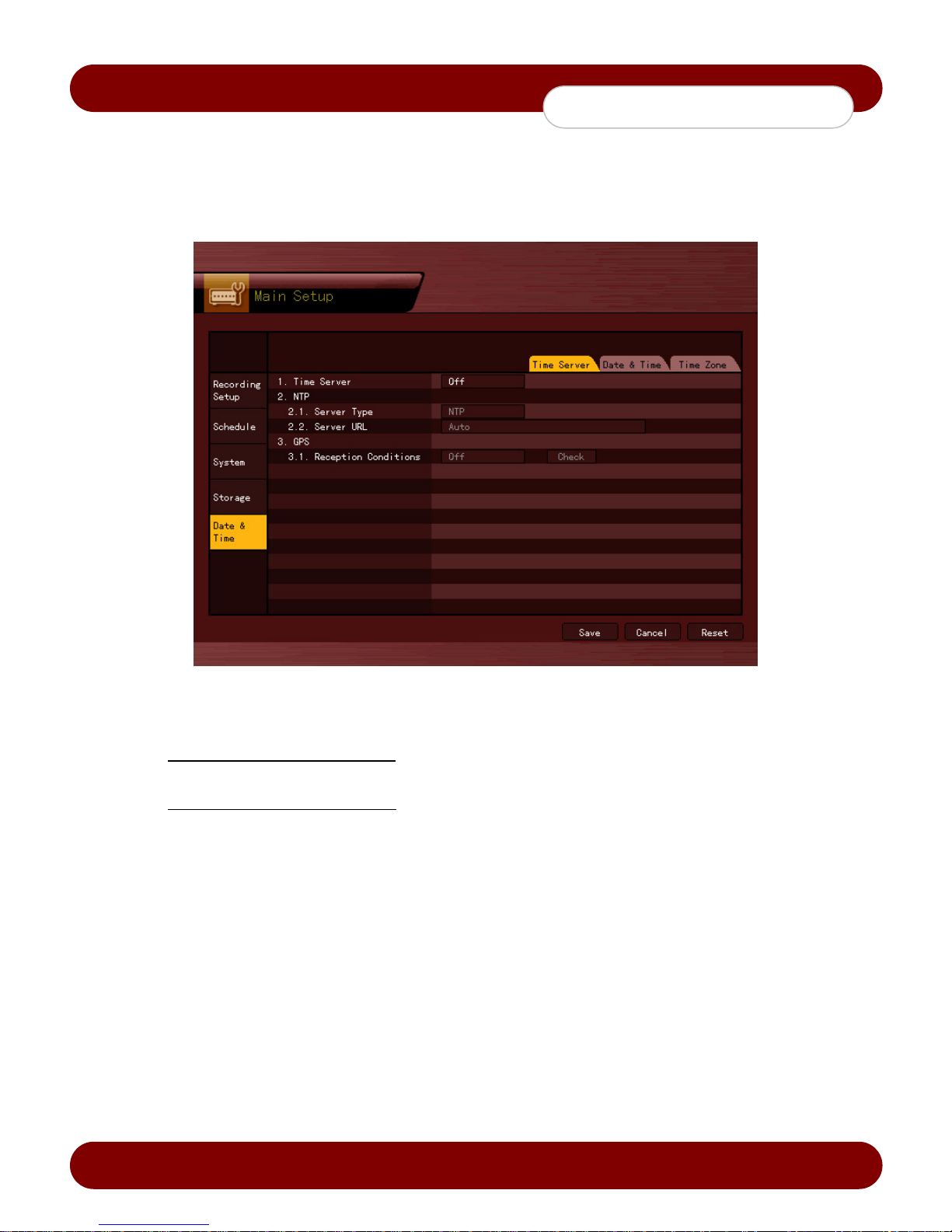
c
eSync DVR Manual
System Setup
5-1-9 NTP
This is the protocol for synchronizing the time between the devices connected through the Internet or GPS.
1) Selecting the Date & Time Menu
1) Select {Main Setup} and {Date & Time}.
[Figure 5-11. NTP Setup Window]
2) Description of features
1. Time synchronization
Synchronizatio n with the GPS server
Time will be automatically synchronized every hour with the GPS Server.
Synchronization with the NTP Server
Time will be automatically synchronized every hour with the NTP Server.
A. Automatic Setup
The nearest server from the user’s zone will be selected for connection. If the connection fails, the
next nearest server will be chosen.
B. User Setup
The user sets the URL or IP for the NTP server. If connection is not established, a message will be
sent to the user, and the related log will be saved.
If synchronization with the NTP server fails, synchronizati on with RTC will be established.
2. Daylight saving time (DST) setup
DST is automaticall y pr ocessed according to the time schedule set by the user.
3. User time setup
The user can set the time manua lly.
Revision A - 51 - © 2008 eSync Manual © eSyn
Page 53

c
eSync DVR Manual
System Setup
2) Time Server
1. Select {Time Server} using the arrow keys and press the [Select] button.
2. On the selection window, select {Time Server} by using the arrow keys and press the [Select] button.
OFF - The time server is not used.
NTP - NTP is used to set the time for the DVR.
GPS - GPS is used to set the time for the DVR.
To enable GPS feature, select {Main Setup} {System} {RS232C Port} {GPS Time Server}.
3) NTP - When {Time Server} is NTP, the user can set NTP settings.
1) Server type setup
1. Select {Server Type} by using the arrow keys and press the [Select] button.
2. In the selection box, select the server type using the arrow keys and press the [Select] button.
2) Server URL
1. Select {Server URL} by using the arrow keys and press the [Select] button.
2. In the selection box, select the server URL using the arrow keys and press the [Select] button.
3. The user can enter the IP onl y when the server type is DVR. For the NTP server, Automatic, IP, or URL
should be selected.
4) GPS Reception Status
The reception state can be checked when {Time Server} is GPS.
Password (OK) Satisfactory reception state
Not Good (NG) Unsatisfactory reception state
5) Changing the system date and time
The system date and time format is Year/Month/Day Hour/Minute/Second.
To set the display format, select {Main Setup} {System} {Time Display Format}.
6) Selecting Time Zone
1. Select {Time Zone} by using the arrow keys and press the [Select] button.
2. On the selection window, select the time zone you want to set.
7) Daylight Saving Time
1. Select {Daylight Saving Time} by using the arrow keys and press the [Select] button.
2. On the selection window, select [On] or [Off] to enable or disable the DST feature.
Start and End Time can be changed manually.
After the DST is selected, the existing data will be displayed as “OLD_” in the search and
log list.
Revision A - 52 - © 2008 eSync Manual © eSyn
Page 54
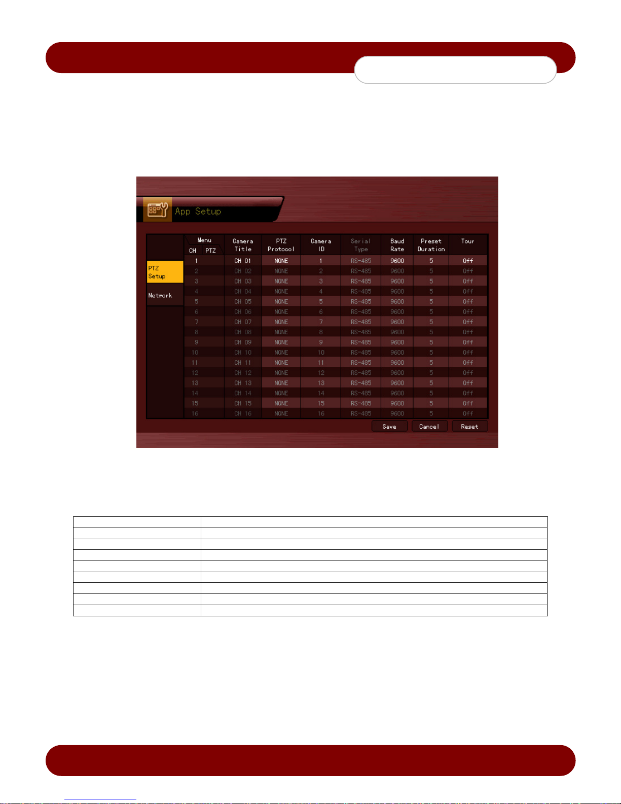
c
eSync DVR Manual
Application Setup
5-2 Application Setup
Application Setup includes the PTZ setting and network setting.
5-2-1 Selecting the Application Setup Menu
1. On the Live mode window, press the {Menu Button} {Application Setup}.
2. The Application Setup window will appear as shown in Figure 5-12.
[Figure 5-12. PTZ Setup Window]
5-2-2 PTZ setup
Used to set the PTZ camera connected to the system
Menu CH
Menu PTZ
Camera Title
PTZ Protocol
Camera ID
Serial Type
Baud Rate
Preset Duration
Tour
Displays Channel Numbers
Displays an PTZ Icon when the PTZ Protocol is set
Title for each channel
Sets the protocol for PTZ camera
PTZ ID setup
Set to RS-485 only
Communication speed
Time interval between the presets while on Tour mode
Sets the Tour feature (Tour 1 and Tour 2)
Revision A - 53 - © 2008 eSync Manual © eSyn
Page 55

c
eSync DVR Manual
System Setup
1) PTZ Protocol Setting
1. Select the PTZ protocol from the list.
2) Camera ID setup
1. The camera ID must be the same as the ID set on the PTZ camera.
2. Select the camera ID for the channel.
3) Setting the baud rate
1. Select the baud rate for the PTZ.
4) Preset Time setting
1. Set the interval time per preset in tour mode (select between 5 and 60 seconds)
5) Tour Setup
1. Enable Tour mode, Tour 1 is set to preset 9, and Tour 2 is set to preset 0.
Revision A - 54 - © 2008 eSync Manual © eSyn
Page 56
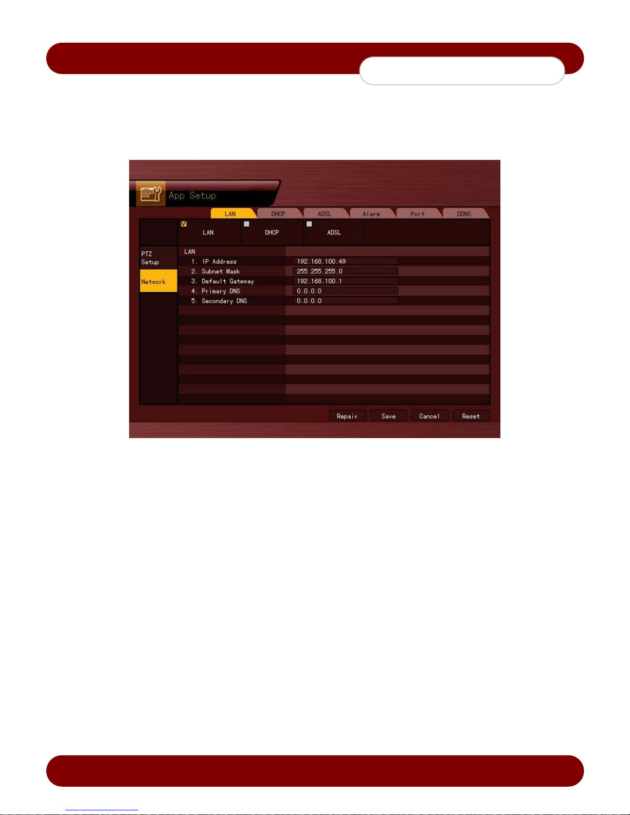
c
eSync DVR Manual
System Setup
5-2-3 Network setup
To set the network settings on the DVR
1) Selecting the Network Setup Menu
1. In the {Application Setup} mode, select {Network} using the arrow keys.
[Figure 5-13. Network Setup Window]
2) LAN- Assign a static IP address to the DVR
1. Select {LAN} by using the arrow keys and press the [Select] button.
2. Enter the IP address, subnet mask, default gateway, default DNS, and auxiliary DNS (optional) by using the
arrow keys, numeric buttons, and press the [Select] button.
3) DHCP - Assign a dynamic IP address to the DVR
1. Select {DHCP} using the arrow keys and press the [Select] button.
2. Use the [Repair] option to obtain a DHCP lease from the router or gateway.
4) ADSL
1. Select {ADSL} by using the arrow keys and press the [Select] button.
2. Enter the user account (ID) and password given by ISP.
5) Alarm - To setup for email notification in case of an event
To use this feature, the Call or Mail Alarm must be turned ON in {Main Setup} {Data Setup}.
1. Select {Alarm} by using the arrow keys and press the [Select] button.
2. Enter the information on the window to receive email notifications.
Revision A - 55 - © 2008 eSync Manual © eSyn
Page 57

c
eSync DVR Manual
System Setup
6) Ports
The default value is from 2000 through 2007.
The default value is 80 for the web server.
Default values can be changed, depending o n network setup and ISP.
1. Select {Port} using the arrow keys and press the [Select] button.
2. Enter the port number and save it using the arrow keys and press the [Select] button.
7) DDNS
The default value is set to eSync DDNS server.
1. Select {DDNS} using the arrow keys and press the [Select] button.
2. In order to use DynDNS, the user is required to register through DynDNS, and enter the account informa tion.
Revision A - 56 - © 2008 eSync Manual © eSyn
 Loading...