

ESYLUX PROTECTOR K RADIO MODULE User Manual
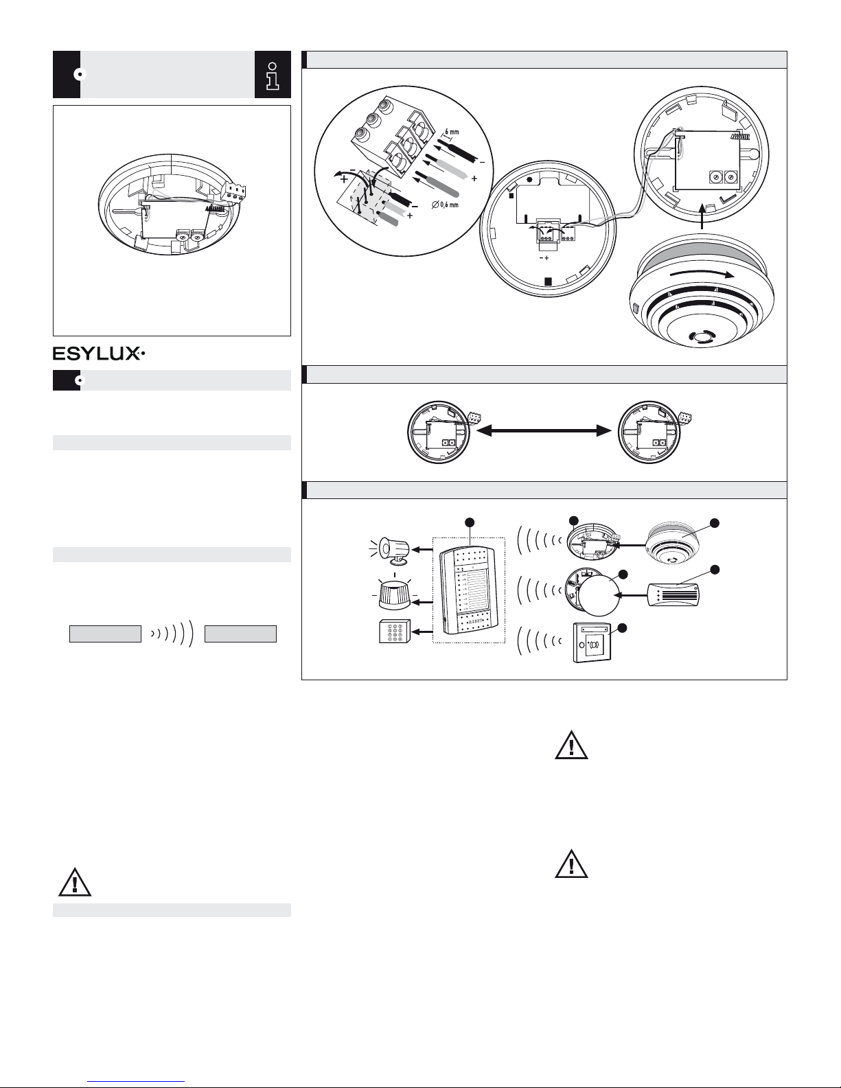
FIG. 1
A
B
C
D
E
F
1
2
3
4
5
6
7
8
9
A
B
C
D
E
F
1
2
3
4
5
6
7
8
9
9V
9V
9V
9V
FIG. 2
A
B
C
D
E
F
1
2
3
4
5
6
7
8
9
A
B
C
D
E
F
1
2
3
4
5
6
7
8
9
A
B
C
D
E
F
1
2
3
4
5
6
7
8
9
A
B
C
D
E
F
1
2
3
4
5
6
7
8
9
> 1 m
FIG. 3
A
B
C
D
E
F
1
2
3
4
5
6
7
8
9
A
B
C
D
E
F
1
2
3
4
5
6
7
8
9
1
2
5
3
4
6
GB
RADIO HOME SMOKE DETECTION SYSTEM
A
B
C
D
E
F
1
2
3
4
5
6
7
8
9
A
B
C
D
E
F
1
2
3
4
5
6
7
8
9
• • PROTECTOR K RADIO MODULE
www.esylux.com
PROTECTOR K RADIO MODULE
GB
Congratulations on your purchase of this high-quality ESYLUX product. To
ensure proper operation, please read these user instructions carefully and
keep them for future reference.
1 • SAFETY INSTRUCTIONS
Use this product only as intended (as described in the user
instructions). Changes or modifications to the product or
painting it will result in loss of warranty. You should check
the device for damage immediately after unpacking it. If there
is any damage, you should not install the device under any
circumstances. If you suspect that safe operation of the device
cannot be guaranteed, you should turn the device off
immediately and make sure that it cannot be operated
unintentionally.
2 • DESCRIPTION
• The ESYLUX PROTECTOR radio home smoke detection
system is designed for domestic use or similar.
• The radio home smoke detection system consists of:
• If smoke is detected by one of the radio smoke detectors,
it will start to flash and emit an audible warning signal.
At the same time, it will send a signal to the radio control
centre which will immediately indicate the exact location
of the source of the fire by activating an audible and visual
alarm.
Every second counts in an emergency!
• The RF signal is transmitted in one direction only. The radio
control centre (Fig. 3.1) does not transmit radio frequency
signals but receives alarm and flat battery signals from the
following radio transmission units:
- PROTECTOR K radio module (Fig. 3.2) in conjunction with
PROTECTOR K or PROTECTOR K lithium 9 V smoke
detectors (Fig. 3.3)
- Universal radio transmitter module (Fig. 3.4) in conjunction
with other components, such as gas detector
PROTECTOR GD 230 V AC (Fig. 3.5)
- The alarm can be triggered using the radio call point (Fig. 3.6)
NOTE: The PROTECTOR radio home smoke detection system
cannot be used in conjunction with the PROTECTOR K
RF-transceiver or Mobil-PROTECTOR-RF remote control.
3 • INSTALLATION / ASSEMBLY / CONNECTION
• When installing a radio system, the individual requirements
of each building/house should be taken into account. Radio
systems can be weakened or disrupted by various factors.
Therefore it is important that you read these operating
instructions thoroughly and that you also read the
supplementary sheet entitled „Notes on radio operation“
and the radio control centre‘s operating instructions.
• Before permanently mounting the radio home smoke
detection system, we recommend that you test the entire
system.
3.1 Preparing the smoke detector for connection to the
PROTECTOR K radio module
• The PROTECTOR K radio module and smoke detector
PROTECTOR K (or alternatively PROTECTOR K lithium) share
the same battery, which is housed inside the smoke
detector (see the instructions for the smoke detector). This
reduces battery life. The radio control centre monitors the
battery and indicates when it is time to change it.
We recommend Ultralife U9VL lithium batteries.
• Close the smoke detector battery compartment.
The red LED on the smoke detector will flash every
45 seconds to indicate that the battery is fitted correctly.
3.2 Preparing the PROTECTOR K radio module
The PROTECTOR K radio module features the following rotary
programming knobs:
3.2.1 „System code“ rotary knob (Fig. 1.1) – possible adjustments:
Position A - F = system code A - F
• Assign the same system code (A – F) to the radio transmitter
units as the radio control centre.
• Note: The radio control centre only processes radio data
messages containing the same system code.
You must therefore assign all radio transmitter units the
same system code (A – F) as the radio control centre.
This will avoid other radio systems (e.g. neighbouring
systems) causing interference or disturbance on your system.
3.2.2 „Detector number“ rotary knob (Fig. 1.2) – possible adjustments:
Position 1 - 8 = detector number 1 - 8
• Set a detector number (1 – 8) on the radio transmitter
module corresponding to the required alarm circuit (1 – 8)
on the radio control centre.
Note: Only one radio transmitter unit can be assigned to each alarm circuit.
• Remove the green 2-pin terminal from the underside of the
smoke detector and replace it with the 3-pin terminal of the
radio module (Fig. 1).
CAUTION: Make sure the cables are connected correctly.
black = negative (-)
brown = signal cable/networking (+)
red = +9 V power supply for the PROTECTOR K radio module
• Thus the smoke detector supplies the PROTECTOR K radio
module with power. The connection also allows the radio
module to be registered by, and stored on, the radio control
centre.
• Decide where to position the PROTECTOR K radio module.
Refer to the supplementary sheet entitled „Notes on radio
operation“ and to the smoke detector‘s operating instructions.
NOTE: When deciding on the location, ensure that all the
components are placed in the best possible positions.
Radio transmitter unit
Radio module +
(retrofittable)
smoke detector
RF signals
Unidirectional
transmission
Radio control centre
(8 detector circuits)
Receiver
Symbol description
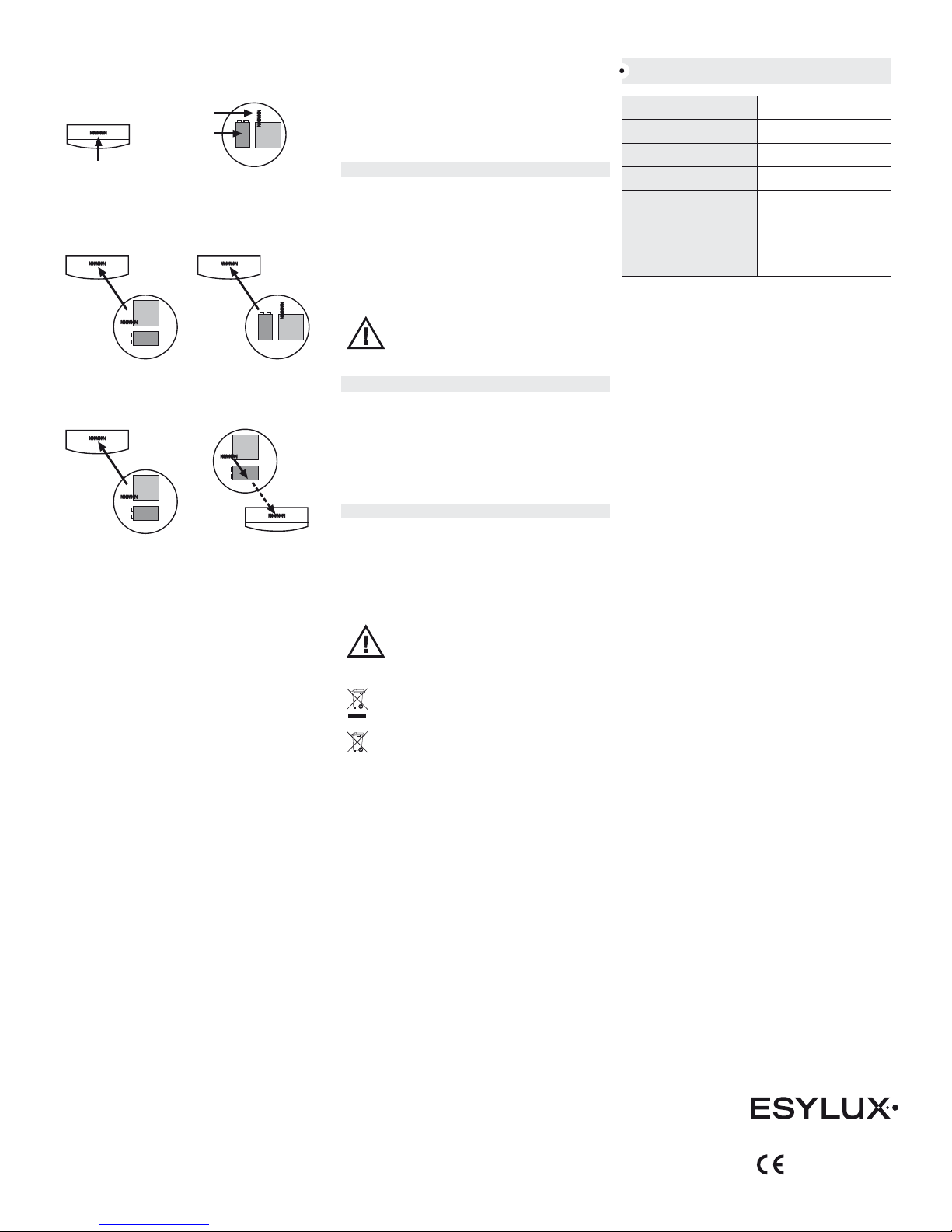
Aligning the aerials
Ensure that the radio transmitter unit aerials are aligned as
parallel as possible with the radio control centre and repeater
aerials.
When positioning the radio transmitter units, make sure that
their batteries are placed behind the transmitter and receiver
aerials, and not directly between them.
• Put the smoke detector onto the PROTECTOR K radio
module and turn the smoke detector in a clockwise direction
until it clicks into place.
Make sure that the connecting cables (Fig. 1.3) are on the
side of the box so as not to impair the radio range.
• Provisionally fix the PROTECTOR K radio module in place
using adhesive tape, for example.
• Then press the test button (for up to 20 seconds) until the
smoke detector alarm is activated.
Check the LEDs on the radio control centre.
The red alarm LED (1 – 8) corresponding to the pre-programmed
detector circuit should light up and the control centre buzzer
should emit a continuous tone.
3.3 Using the PROTECTOR radio system test receiver to test the system
The PROTECTOR radio system test receiver (not included –
available as an accessory) provides reliable information about
radio link quality.
• Radio wave transmission range depends on various
constantly changing environmental factors (see the
supplementary sheet entitled „Notes on radio operation“).
By measuring the radio link quality, you can determine the
best possible location in which to position your radio
transmitter units and radio control centre. Moving a radio
transmitter unit or the radio control centre just 30 cm to the
right or left can alter the transmission range.
• If moving the radio transmitter unit and/or radio control
centre does not improve the transmission range, position a
PROTECTOR radio signal repeater (not included – available
as an accessory, depending on the country) as centrally as
possible between the radio control centre and the radio
transmitter unit.
Note: Only one PROTECTOR radio signal repeater can be used for each
radio home smoke detection system.
Refer also to the ESYLUX PROTECTOR radio signal repeater‘s
user instructions.
• Then test the radio link quality again with the PROTECTOR
radio signal repeater.
3.4 Final installation
• Once you have determined the best possible positions for all
your radio transmitter units and for the radio control centre,
fix the radio transmitter units permanently in place.
• After starting up the system and briefing the customer,
we recommend that you fit the radio transmitter units with
9 V lithium batteries (Ultralife U9VL) to ensure that the
batteries last as long as possible.
3.5 Enhancing the radio system
• An additional radio transmitter unit can be registered in one
of the following ways: fit the batteries into the radio
transmitter unit, perform a test alarm or wait at least 1 hour
for the periodical status report to automatically acknowledge
and store the unit.
3.6 Removing an item from the radio system
• If you wish to remove a radio transmitter unit from the
system, you cannot just remove it, as the radio control centre
will register a problem with the radio link and permanently
display an error LED. You must therefore also fully disable
the radio control centre (remove the power supply unit and
battery). This will cancel all the radio transmitter units. Once
the radio control centre has been switched back on, these
units must be re-registered.
4 • IMPORTANT NOTES
As radio waves have particular characteristics, also read the
supplementary sheet entitled „Notes on radio operation“.
• Do not use in areas with extreme temperature variations or
in damp rooms.
• Respect the minimum distance between radio transmitter
units (Fig. 2).
• Do not place near power-consuming equipment.
Radio transmission range and interference can be affected by:
• Foil-coated wool, aluminium foil, cladding and metal
window panes.
NOTE: Carry out regular functional tests in accordance with
the device‘s instructions. Test it again if the environmental
conditions change (e.g. new floors, new or moved furniture,
lights, construction changes, etc.) and after replacing the
battery.
5 • TESTING / MAINTENANCE
• Press and hold the test button to trigger the smoke detector‘s
alarm. To do this, refer to the smoke detector‘s instructions.
• Test the associated circuits on the radio control centre.
The red alarm LEDs (1 – 8) for the relevant detector circuits
should light up.
• Press the RESET button on the radio control centre to reset
the alarms and displays.
• Replace flat batteries immediately.
• Test the equipment after replacing the battery.
6 • SYSTEM COMPONENTS
ESYLUX PROTECTOR radio control centre
ESYLUX PROTECTOR K radio module
ESYLUX PROTECTOR K and PROTECTOR K lithium
ESYLUX PROTECTOR radio call point
ESYLUX PROTECTOR universal radio transmitter module
ESYLUX PROTECTOR radio signal repeater
ESYLUX PROTECTOR radio system test receiver
NOTE: ESYLUX GmbH hereby declares that the product
PROTECTOR K radio module complies with the basic
requirements and other relevant provisions of
Directive 1999/5/EC. The full text of the declaration of
conformity can be found at www.esylux.com.
NOTE: this device must not be disposed of as unsorted
household waste. Used devices must be disposed of correctly.
Contact your local town council for more information.
NOTE: used batteries must not be disposed of as unsorted
household waste. Used batteries must be recycled and may
be returned free-of-charge to the place of sale. Batteries
contain substances which are harmful to the environment and
to human health and must therefore be disposed of correctly.
TECHNICAL DATA
BATTERY OPERATION 9 V from smoke detector
RECOMMENDED BATTERIES Ultralife U9VL (Lithium)
FREQUENCY 868.35 MHz
TRANSMISSION POWER < 10 mW
OPERATING TEMPERATURE
RANGE
0 °C…+45° C
COLOUR white
APPROX . MEA SUREM ENTS Ø 106 mm, height 20 mm
Technical and design features may be subject to change.
ESYLUX GmbH
An der Strusbek 40, 22926 Ahrensburg/Germany
Internet: www.esylux.com
e-mail: info@esylux.com
TBL 12/2010
Top view of radio
transmitter unit
Top view of radio
control centre
Aerial
Aerial
Battery
Correct Incorrect
Correct Incorrect
 Loading...