

GB
OPERATING INSTRUCTIONS
PD-C360i/8 mini KNX (EP10426155)
PD-C360i/12 mini KNX (EP10426162)
from version D
www.esylux.com
1
/12
••
PD-C360i/8 mini KNX
••
PD-C360i/12 mini KNX
www.esylux.com
OPERATING INSTRUCTIONS
GB
Congratulations on your purchase of this high-quality ESYLUX product. To ensure correct device operation,
please read these installation/operating instructions carefully and keep them in a safe place for future
reference.
1 • SAFETY INSTRUC TIONS
CAUT ION: work on t he 230 V power s ystem must b e carried out b y authoris ed personn el only with
due regard to the applicable installation regulations. Switch off the power supply before installing
the system.
Use this product only as intended (as described in the user instructions). Changes or
modifications to the product or painting it will result in loss of warrant y. You should che ck the
device for damag e immedi ately after unpacking it. If there is any damage, you sh ould not
install the device under any circumstances.
If you suspect that safe ope ration of the devi ce canno t be guaranteed, you should turn the
device off immediatel y and make sure that it cannot be operate d unintentionally.
NOTE: t his device m ust not be dis posed of as uns orted hous ehold wast e.
Used dev ices must be d isposed of co rrectly. Co ntact your l ocal town co uncil
for more information.
2 • DESCRIPTION
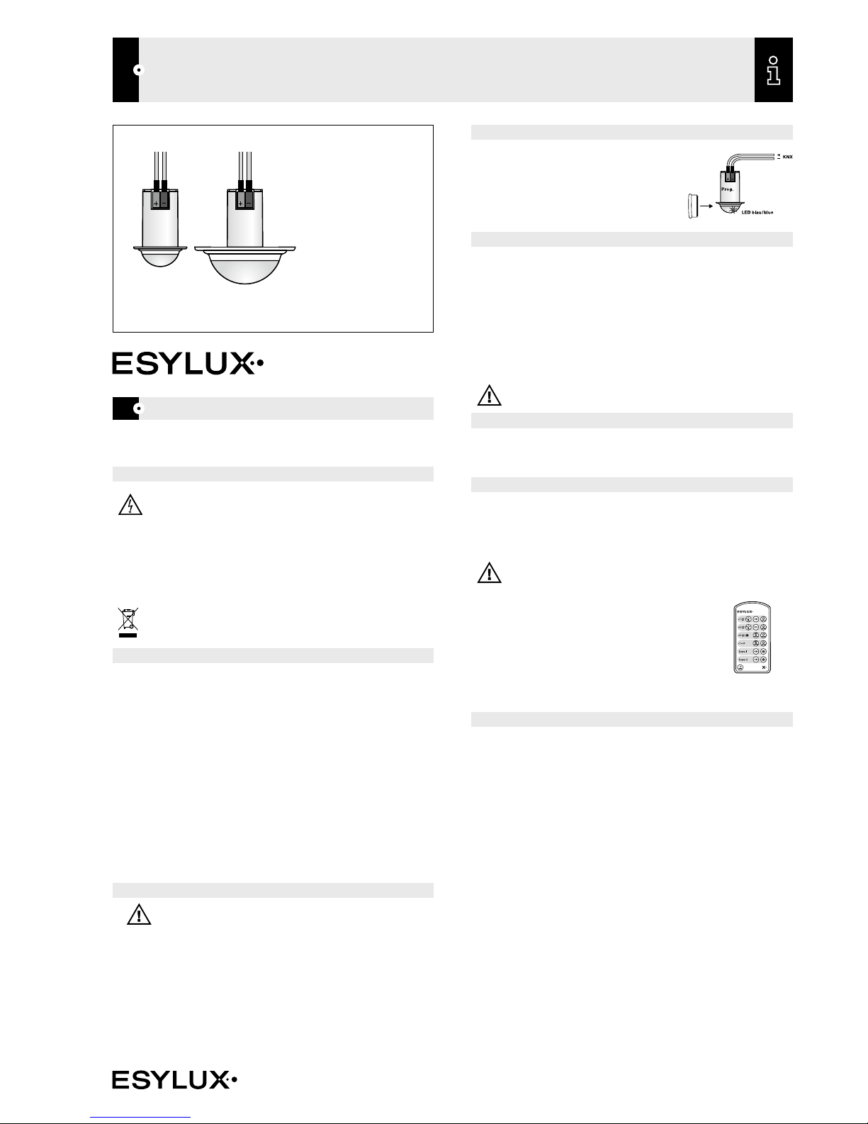
The ESYLUX PD-C360i/8 and 12 mini KNX are presence detectors with a 360°field of
detection and integrated bus coupler designed for ceiling mounting. Follow the installation
instructions provided when installing the device. The detector is able to control lighting
("switching" or "constant light control" features).
For additional features, please refer to the “Description of applications” section of the operating
instructions. With a range of up to 8 m or 12 m in diameter, the presence detector is suitable for
use in offices, classrooms, conference facilities and passageways with natural lighting.
The PD-C360i/8 and 12 mini KNX are only intended for use in a KNX (EIB), TP (twisted pair)
bus system in conjunction with other KNX components.
If the PD-C360i/8 or 12 mini KNX detects that persons are present in its field of detection, it
transmits regulating or controlling telegrams for light outputs, depending on ambient brightness,
and for HVAC(heating, ventilation and air conditioning) objects.
• Blended light measurement is suitable for FL, PL, halogen and incandescent lamps.
Certified KNX/EIB training centres provide specialist training on how to plan, install, activate,
document and use the ETS (Engineering Tool Software) that is required for parameter setting.
3 • INSTALLATION / ASSEMBLY / CONNECTION
See separate installation instructions.
Mobil-PDi/User
4 • START-UP
All parameter settings are carried out via the ETS
(Engineering Tool Software). The magnet provided
can be used to activate the programming status for the
physical address on the PD-C360i/8 and 12 mini KNX.
This is indicated by the blue LED. The product database
and application description are available to download
at www.esylux.com.
5 • SWITCH-ON BEHAVIOUR / LED DISPLAY
• Connect the bus supply
This initiates a warm-up phase that lasts approx. 10 seconds.
The red LED and green LED will slowly flash alternately (f = 1 Hz).
• LED display after warm-up
Each time motion is detected, this is indicated by 2 x flashes of the preset LED colour.
• In the "Master" function, the remote control entries will be acknowledged
by 3 flashes from the blue LED .
• In the "Slave" function, each detected movement is acknowledged by 2 flashes from the green LED.
NOTE: The green LED will only light up when motion is detected if it has been enabled by the ETS
(Engineering Tool Software).
6 • TEST MODE
Parameters can be set via the ETS (Engineering Tool Software).
Test mode switches to the RUN status after “storing”, or 10minutes after activating the test
mode. The blue LED flashes to indicate movement.
7 • REMOTE CONTROL
The optional user remote control Mobil-PDi/User (EM10425547) can be used to regulate/
control the lighting.
The Mobil-PDi/User remote control adjusts the value for the period that persons are present plus
the switch off time. Thereafter, the values set via the ETS (Engineering Tool Software) will apply.
NOTE: In the "Slave" function the detector does not respond to the remote control!
The Mobil-PDi/User can be used to control the lighting as follows:
• switching on or off
• dimming (only with “controlling” feature)
• storing and calling up of 2 scenes
• pressing the "Reset" button resets the KNX presence detector
to the values set via ETS (Engineering Tool Software). The stored
light scenes 1 + 2 are kept.
For further information, please refer to the operating instructions
for the Mobil-PDi/User remote control.
8 • ESYLUX MANUFACTURER’S GUARANTEE
ESYLUX prod ucts are t ested in a ccordance with applicable regulatio ns and manufactu red
with the u tmost care. The guarantor, ESYLUX Deutsc hland GmbH, Post fach 1840, D -22908
Ahrensb urg, Ger many (for Germany) or the relevant ESYLUX di stributor in your c ountr y (visit
www.es ylux.com for a complete overview) provides a guarantee against manufacturing/
materi al defects in ESYLUX device s for a per iod of three years from the date of manufacture.
This guarantee is indepen dent of your legal r ights wi th respect to the s eller of t he devic e.
The guara ntee does not apply to natural wear an d tear, chan ges/interference caused by
environmental factors or damage i n transit, nor to damage caused as a resul t of failure to
follow th e user or maintenance instructio ns and/or as a result of improper installation. Any
illuminants or batteries supplied wit h the devi ce are not covered by the guarantee.
The guara ntee can only be honoured if t he devic e is sent back with the invoic e/receipt,
unchanged, packed and with sufficient postage to the guarantor, along with a brief
description of the fault, as soon as a d efect has been id entified.
If the guarantee claim prove s justif ied, the g uaranto r will, within a reasonable period, either
repair the device or replace it. The guarante e does not cover fur ther claims; in par ticular,
the guara ntor will not be liable for damages re sulting from the d evice’s defe ctiveness. If the
claim is unfounde d (e.g. because the guarantee has expired or the fa ult is not covered by th e
guarantee), then the guarantor may at tempt to repair th e device for you for a f ee, keeping
costs to a minimum.

GB
OPERATING INSTRUCTIONS
PD-C360i/8 mini KNX (EP10426155)
PD-C360i/12 mini KNX (EP10426162)
from version D
www.esylux.com
2
/12
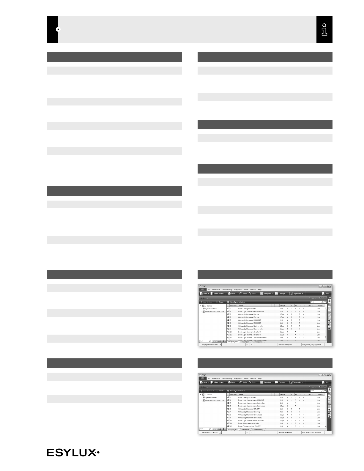
LIGHT CHANNEL OBJECTS
Object 0: "Input: Lock light channel" (length = 1-bit)
The switching/dimming outputs for the light channel are locked with an
ON telegram and unlocked with an OFF telegram.
Parameters can be set to determine the status of the light channel after
locking and unlocking.
Object 1: "Input: Light channel manual ON/OFF" (length = 1-bit)
Note: essential when in half automatic mode!
Manual operation is maintained when persons are present until the switch
off time has elapsed if "while presence" is set in the parameters. Light
measurement is not active if the parameter "With disabled light processing
during off-period" has been selected. After this, the detector switches to
normal operating mode. Manual operation has no impact on motion
detection. The function is transmitted to communication objects 5/6.
Object 2: "Input: Light channel manual dimming" (length = 4 bits)
Function: active when constant light control/regulation has been selected!
Input for dim up/dim down KNX touch sensors. Writing on this object
manually overrides the light channel and the commands are transmitted to
the dimming actuator via object 7.
Manual operation is maintained when persons are present until the switch
off time has elapsed if "while presence" is set in the parameters. Light
measurement is not active if "With disabled light processing during off-period"
has been selected. After this, the detector switches to normal operating mode.
Manual operation has no impact on motion detection.
Object 3: "Input: Light channel manual dim value" (length = 1 byte)
Function: active when constant light control/regulation has been selected!
Input to preset dim values. Writing on this object manually overrides the light
channel and the values are transmitted to the dimming actuator via objects
8 and 9.
Manual operation is maintained when persons are present until the switch
off time has elapsed if "while presence" is set in the parameters. Light
measurement is not active if "With disabled light processing during off-period"
has been selected. After this, the detector switches to normal operating mode.
Manual operation has no impact on motion detection.
Object 4: "Input: Light channel control/regulating without presence" (length = 1 bit)
Operating mode: controlling
This object can be used to enable light control without presence.
Operating mode: regulating
This object can be used to enable light regulation without presence.
Object 5: "Output: Light channel ON/OFF" (length = 1-bit)
If artificial lighting is required (threshold 1/set value via parameter) and
persons are present, the output sends an ON telegram.
If natural light is sufficient and/or no persons are present, an OFF telegram
is sent once the switch off time has elapsed.
Object 6: "Output: Light channel 2 ON/OFF" (length = 1-bit)
Function: switching - only available with switching function!
If artificial lighting is required (difference between threshold 2 and threshold
1 via parameter) and persons are present, the output sends an ON telegram.
If natural light is sufficient and/or no persons are present, an OFF telegram is
sent once the switch off time has elapsed.
Object 7: "Output: Light channel dimming" (length = 4 bits)
Function: constant light control/regulation
Telegrams can be transmitted to the dimming actuator via this object by
manually pressing and holding down a touch sensor (object 2). only active
when "constant light control/regulation" has been enabled!
Object 8: "Output: Light channel dim value 1" (length = 1 byte)
Function: constant light control/regulation
If artificial lighting is required and persons are present, the output sends a
value telegram (1byte). If natural light is sufficient (controller to minimum)
and/or no persons are present, the lighting is set to 0 % or the device
switches to orientation lighting once the switch off time has elapsed. only
active when "constant light control/regulation" has been enabled!
Object 9: "Output: Light channel dim value 2" (length = 1 byte)
Function: constant light control/regulation
If artificial lighting is required and persons are present, the output sends a
value telegram (1byte).
If natural light is sufficient (controller to minimum) and/or no persons are
present, the lighting is set to 0 % or the device switches to orientation lighting
once the switch off time has elapsed.
Option to offset dim value 2 and dim value 1 via parameter. only active
when "constant light control/regulation" has been enabled!
Object 10: "Input: Light channel 1 threshold" (length = 2 byte)
(Operating mode: switching)
This object can be used to specify the threshold (lux) for channel 1 via
telegram. This is only available if "threshold via telegram" has been selected.
Object 10: "Input: Light channel set value control" (length = 2 byte)
(Operating mode: controlling)
This object can be used to specify the set value (lux) for light control via
telegram. This is only available if "threshold via telegram" has been selected.
Object 10: "Input: Light channel regulating lower light value" (length = 2 byte)
(Operating mode: regulating)
This object can be used to specify the lower light value (lux) for light
regulation via telegram. This is only available if "threshold via telegram"
has been selected.
Object 11: "Input: Light channel 2 threshold" (length = 2 byte)
(Operating mode: switching)
This object can be used to specify the threshold (lux) for channel 2 via
telegram. This is only available if "threshold via telegram" has been selected.
Object 11: "Input: Light channel regulating upper light value" (length = 2 byte)
(Operating mode: regulating)
This object can be used to specify the upper light value (lux) for light
regulation via telegram. This is only available if "threshold via telegram"
has been selected.
Object 12/13: "Input: Light channel 1/2 actuator feedback" (length = 1 bit)
Function: constant light control/regulation
This object can be used to evaluate the status object of an actuator. In the event
that the actuator is not only controlled by the detector, the detector will be
switched on with an ON telegram and then switched off once the switch off time
has elapsed (provided no further movement is detected). If an OFF telegram is
sent, the detector will be switched off and will then revert immediately to standy
mode. This is only available if "actuator feedback" has been enabled.
Object 14: "Input: Select orientation light" (length = 1 bit)
Function: constant light control/regulation
An ON telegram changes the setting from orientation light value 1 to orientation
light value 2, while an OFF telegram switches it from value 2 to value 1.
Object 15: “Input: Orientation light ON/OFF” (length = 1 bit)
Function: constant light control/regulation
An OFF telegram is used to switch off the orientation light function, while an
ON telegram switches it on.
GB
OPERATING INSTRUCTIONS
PD-C360i/8 mini KNX (EP10426155)
PD-C360i/12 mini KNX (EP10426162)
from version D
www.esylux.com
3
/12
LIGHT VALUE OBJECTS
Object 16: "Input: Lock sending light value" (length = 1 bit)
An ON telegram locks sending, while an OFF telegram enables sending of
the internal light value. This is only active if "Behaviour at switching on lock"
has been enabled.
Object 17: "Input: External light value" (length = 2 bytes)
This object can be used to mix an external light value with the internal one for the
actual value for constant light control/regulation. This is evaluated using multipliers.
Object 18: "Output: Internal light value"
This object can be used to output the internal light value without offset or
factor values.
Object 19: "Output: Current light value"
This object can be used to output the light's current actual value. This takes
into account the offset, the internal light value factor and the external light
value factor and value. This value is used by the light channel and the twilight
switch to evaluate the light value.
HVAC CHANNEL OBJECTS
Object 20: "Input: Lock presence (HVAC)" (length = 1 bit)
The switching output for the HVAC channel is locked with an ON telegram
and unlocked with an OFF telegram.
Parameters can be set to determine the status of the channel after locking
and unlocking.
Object 21: "Output: Presence (HVAC) ON/OFF" (length = 1 bit)
If persons are detected, depending on the input delay, an ON telegram is sent.
If no persons are detected, depending on the switch off time, an OFF
telegram is sent.
MOTION OBJECTS
Object 22: "Input: Slave/master motion" (length = 1 bit)
Trigger input for parallel connection of Master/Master or input of Slave.
Object 23: "Input: Lock motion detection" (length = 1 bit)
An ON telegram locks the internal motion detection function, while an OFF
telegram unlocks it again.
Object 24: "Output: Motion detection" (length = 1 bit)
Output of own PIR motion detection.
TWILIGHT SWITCH OBJECTS
Object 27: "Output: Twilight switch dim value" (length = 1 by te)
This communication object can be used to output a parametrisable dim
value ranging from 0 - 100%.
Object 28: "Output: Twilight switch scene" (length = 1 byte)
Individual scenes (1 of 64) can be called up for switch ON and switch OFF.
PRESENCE SIMULATION OBJECT
Object 29: "Input: Presence simulation ON/OFF" (length = 1 bit)
Presence simulation is switched on or off.
NIGHTLIGHT OBJECT
Object 30: "Input: Nightlight ON/OFF" (length = 1 bit)
The nightlight function is switched on or off - the motion detection/locking
display is retained.
Object 31: “Input: Lock alarm” (length = 1 bit)
“1” locks the alarm function, while “0” unlocks the alarm function.
Object 32: “Output: Alarm ON/OFF” (length = 1 bit)
An alarm is triggered if a continuous number of movements are detected within
a parametrisable time frame.
Different time frames can be defined for the switching ON and OFF of a alarm.
TWILIGHT SWITCH OBJECTS
Object 25: "Input: Twilight switch manual ON/OFF" (length = 1 bit)
Manual override remains active until the off-period has elapsed.
Object 26: "Output: Twilight switch ON/OFF" (length = 1 bit)
If ambient brightness falls below the threshold value, the twilight switch
sends an ON telegram once the time delay has elapsed.
If ambient brightness exceeds the threshold value, the twilight switch sends
an OFF telegram once the time delay has elapsed.
Hysteresis can be adjusted using the parameters.
OBJECTS FOR SWITCHING FUNCTION
OBJECTS FOR CONTROLLING/REGULATING FUNCTION
GB
OPERATING INSTRUCTIONS
PD-C360i/8 mini KNX (EP10426155)
PD-C360i/12 mini KNX (EP10426162)
from version D
www.esylux.com
4
/12
DESCRIPTION OF APPLICATION
1. MASTER/SLAVE
The Master detects presence and evaluates it according to set parameters.
"Lighting ON/OFF" or "lighting light value higher/lower"
The Slave is used exclusively to extend the field of detection. Presence is transmitted
to the Master (object 22) for evaluation according to the set parameters.
• Master/Master selection
Two Masters can work in parallel to extend the field of detection.
Each Master evaluates the presence (object 24) according to its parameters
set via the ETS (Engineering Tool Software) and regulates/controls the lighting
appropriately.
Default setting: Master
4. REMOTE CONTROL
This is where you can disable operation via the Mobil-PDi/User or X- REMOTE
(iPhone).
Note: Remote control is disabled in test mode.
2. TEST MODE
(only for Master device configuration)
When test mode "ON" light measurement disabled.
When test mode is enabled, the connection with the lighting system is checked.
If the motion sensor detects movement, the lighting will be "ON" for 5seconds,
followed by a dead time of 1second "OFF".
The blue LED indicates that movement has been detected.
Test ON switches to test OFF automatically after 10minutes, or when the
parameters are stored.
Note: During test Slave input enabled.
3. BEHAVIOUR AFTER ETS DOWNLOAD/RESET
Choose from: "No reaction", "ON", "OFF"
During the process, the following objects are sent:
Switching operating mode:
- Object 5: "Output: Light channel 1 ON/OFF"
- Object 6: "Output: Light channel 2 ON/OFF"
"Controlling" or "regulating" operating mode:
- Object 5: "Output: Light channel ON/OFF"
- Object 8: "Output: Light channel dim value 1"
- Object 9: "Output: Light channel dim value 2"
- Also, object 21: "Output: Presence (HVAC) ON/OFF"

GB
OPERATING INSTRUCTIONS
PD-C360i/8 mini KNX (EP10426155)
PD-C360i/12 mini KNX (EP10426162)
from version D
www.esylux.com
5
/12
5. LED IN SENSOR
Option s: choose between one of t he LED brightn ess levels or "OFF"
If the LED is not switched off, you can specify its colour when motion is detected
(2 x flashes) and when motion detection is locked via object 23. You can use
the parameters to set the brightness of the LED to one of five different levels.
5.1. Nightlight function
This function allows you to use the LED as a nightlight. It will switch to one of the
preset colours as soon as the light value falls below or exceeds the threshold.
You can use object 30 to disable the nightlight.
DESCRIPTION OF APPLICATION
6. MOTION DETECTION
When movement is detected, this status is maintained for the preset time
period. Then, several requests are sent to the sensors each second to determine
whether further motion has been detected (object 24). You can use one of the
parameters to set the sensor's level of sensitivity.
Object 23 can be used to lock motion detection. The LED will display the
colour selected to indicate this.
7. PRESENCE SIMULATION
The detector keeps a constant record of if and when movement has been
detected, for a period of 1 week. An ON telegram via object 29 can then
be used to switch the channels on or off according to this weekly record. The
stored time lapse is taken into account. Normal motion detection also remains
active during this process.
8. EXTERNAL MASTER/SLAVE
This parameter can be used to determine whether the external master/slave
only sends ON telegrams when motion is detected, or whether the external
device sends an ON telegram when motion is detected and OFF telegrams
when no movement is detected.

GB
OPERATING INSTRUCTIONS
PD-C360i/8 mini KNX (EP10426155)
PD-C360i/12 mini KNX (EP10426162)
from version D
www.esylux.com
6
/12
DESCRIPTION OF APPLICATION
9. LIGHT CHANNEL
9.1 Light channel operating mode
• “Full automatic” operating mode
Lighting is automatically switched on if the detector detects presence and the
ambient lighting level has fallen below the preset brightness threshold or set
value. The lighting is automatically switched off if no persons are present and
once the set switch off time has elapsed.
The lighting will also switch off automatically if the preset brightness threshold
or set value is exceeded, regardless of presence.
When persons are present, in order to avoid sudden changes in brightness
caused by undesired switching on/off of the lighting, the detector will only be
triggered after a time delay.
Example: a passing cloud could potentially cause unnecessary switching.
Time delay from "light to dark": 30 seconds.
Time delay from "dark to light": 5 minutes
• Additional manual lighting control in “Full automatic” mode
The lighting can be switched on or off manually using infrared remote control
(Mobil-PDi/User, please also refer to separate Mobil-PDi/User operating
instructions) or by telegrams, e.g. by pressing external KNX/EIB buttons.
If "Manual operation active while presence" is set, the light can be switched on
manually. This will remain switched on for as long as the detector continues to
detect movement, regardless of the ambient brightness.
If "Manual operation active during off-period" is set, the detector turns the lighting to
100% during this period. Once the off-period comes to an end and if there
are persons present, the device will start controlling the light according to the
preset set value.
If no more movement is detected, the detector will revert to the previous automatic
mode after the set switch off time has elapsed.
Note: Applies to all light channel operating modes.
• “Half automatic” operating mode
If “Half automatic” mode has been selected, the lighting must be switched on
manually using infrared remote control (Mobil-PDi/User) or by telegrams, e.g.
by pressing external KNX/EIB buttons. This means that the detector does not
automatically switch "ON" the lighting when persons are present.
However, should the natural lighting level increase and the ambient lighting level
exceed the preset light value, the detector will automatically switch the lighting
off 5minutes after reaching the preset light value, regardless of any presence.
The lighting can subsequently be switched back on manually at any time.
If "Manual operation active during off-period" is set, during this time the detector
behaves in the same way as when the setting "Manual operation active while
presence" is set. The detector then switches to normal operating mode. This
means that the light can be switched on by the user even if the threshold value
has been exceeded, but will then be automatically switched off again once the
preset time has elapsed.
Note: External ON telegram, e.g. through KNX/EIB button, is essential in
“Half automatic” mode! Applies to all light channel operating modes.
Default setting: Full automatic
Light value
No motion
Switch o
time starts
Manual
operation
Switch o
time ends
100 %
Motion 0 %
No control
Manual operation active while presence
Light value
Control with motion
O-period
ends
Switch o
time starts
Switch o
time ends
100 %
Motion
Control
Manual
operation
Manual operation active during off-period

GB
OPERATING INSTRUCTIONS
PD-C360i/8 mini KNX (EP10426155)
PD-C360i/12 mini KNX (EP10426162)
from version D
www.esylux.com
7
/12
DESCRIPTION OF APPLICATION
9.2 Light channel function
Options:
Switching: ON/OFF to a defined threshold.
Controlling: ON/light control to a defined set value/(OFF)
constant light control.
Regulating: light is regulated via linear correlation between
the dim value and the light value.
Default setting: Switching
9.3 Light channel switch off time
• Light channel switch off time
Options: 0seconds, 30seconds – 12hours.
Default setting: 5 minutes
9.4 Processing actuator feedback
Objects 12 and 13 (or object 12 when "controlling" or "regulating" is selected)
can be used to evaluate the status object of an actuator. In the event that the
actuator is not only controlled by the detector, the light channel switches to
standby mode if the status of the channel differs from that of the actuator.
9.5 Cyclic sending
The light channel sends its current status in cycles according to specified time
intervals. At the same time, it is also possible to determine whether it repeatedly
sends OFF or ON telegrams in cycles.
9.6 Behaviour at switching on and switching off lock
Options for each include: "No reaction", "Switch off" or "Switch on" the light
channel.
9.7 Telegram filter
This can be used to prevent OFF or ON telegrams from being sent through
the light channel.
9.8 Lighting controlled regardless of presence
9.9 Lighting controlled/regulated regardless of presence
An ON telegram can be sent via object 4 to initiate light control/regulation
regardless of presence, if this function has been enabled in the parameters (only
visible in controlling/regulating operating mode).

GB
OPERATING INSTRUCTIONS
PD-C360i/8 mini KNX (EP10426155)
PD-C360i/12 mini KNX (EP10426162)
from version D
www.esylux.com
8
/12
10. LIGHT CHANNEL FUNCTION
10.1 Switching
Threshold 0 = deactivated, motion detection only
Threshold 1– 2,000lux (using the up/down menu) or directly enter a value
between 0 and 2,000 lux
Default setting: 500 lux
There is an option of determining an offset (can also be assigned using objects
10 and 11) between "threshold ON/OFF 1" and "threshold ON/OFF 2"
-50 % to +50 %
Default setting: ±0%
Output telegrams can be sent in binary form (objects 5 and 6), as dim values
(objects 8 and 9), (0…100 %), or as scenes (objects 2 and 3), (1… 64).
Individual parameters can be set for the switch ON and OFF values.
10.2 Controlling
• Dim value when controlling begins
Options: 0…100 % (using the up/down menu) or
directly enter a value between 0 and 100 %
Default setting: 60 %
Control timing: Options: 0.5seconds – 10seconds (up/down menu)
Note: If the c ontrol loop ex hibits a hunt ing tendenc y, the sensor can be a djusted to
various illuminants and ballasts using the “control timing” parameter.
As a rule of thumb: t he slower the ligh ting responds, the long er the control ti ming
(0.5…10seconds).
DESCRIPTION OF APPLICATION

GB
OPERATING INSTRUCTIONS
PD-C360i/8 mini KNX (EP10426155)
PD-C360i/12 mini KNX (EP10426162)
from version D
www.esylux.com
9
/12
10.3 Regulating
Lower light value: 0…2,000 lux
Upper light value: 0…2,000 lux
Lower minimal dim value: 0…100 %
Upper maximal dim value: 0...100 %
Note: Always ensure that the maximal value selected is higher than the chosen minimal
value.
Step time: Options: 0.5seconds – 10seconds (up/down menu)
Note: If the control loop exhibits a hunting tendency, the sensor can be adjusted to
various illuminants and ballasts using the “step time” parameter.
As a rule of thumb: the slower the lighting responds, the longer the step time
(0.5 – 10seconds).
Default setting: 2 seconds.
You can specify two light values for light regulation using parameters or telegrams
(communication objects 10 and 11). If the maximal light value is reached, a
telegram is sent with a value of 0 %. If the lower light value is measured, a
telegram is sent with a value of 100 %. In between this, the control variable is
calculated on a linear basis and sent to the dimming actuator (objects 8 & 9).
The externally connected or internal light sensor must be positioned in such a way
to ensure that it receives a large amount of natural light, but little artificial light.
Example
Control variable
max. lux
upper light value
100 %
0 %
min. lux
lower light value
Light value
Setting of minimal and maximal dim value step (0…10 %), enabled during
controlling and regulating.
Setting of minimal and maximal dim value (0…100 %), enabled during controlling
and regulating.
DESCRIPTION OF APPLICATION

GB
OPERATING INSTRUCTIONS
PD-C360i/8 mini KNX (EP10426155)
PD-C360i/12 mini KNX (EP10426162)
from version D
www.esylux.com
10
/12
10.4 Orientation light value
• Orientation light value 1
Options: 0/5 - 50 % (up/down menu) in 5 % steps
Note: only active for "Controlling" and "Regulating"!
The orientation light value 1 is active as standard.
Via Object 14, an ON telegram changes the setting to orientation light value 2
and an OFF telegram changes the setting to orientation light value1.
Only active if orientation light has been set to "ON".
Default setting: 10 %
• Orientation light value 2
Options: 0/5 - 50 % (up/down menu) in 5 % steps
Note: only active for constant light control/regulation!
Only active if orientation light has been set to "ON".
Default setting: 25 %
An OFF telegram via object 15 is used to switch off the orientation light function,
while an ON telegram switches it on. If the orientation light function is switched
off, the detector switches to OFF/0 % once there is no more presence and once
the switch off time has elapsed.
DESCRIPTION OF APPLICATION

GB
OPERATING INSTRUCTIONS
PD-C360i/8 mini KNX (EP10426155)
PD-C360i/12 mini KNX (EP10426162)
from version D
www.esylux.com
11
/12
DESCRIPTION OF APPLICATION
11. HVAC CHANNEL
Note: the presence output is independent of the set light values.
Option of selecting input delay of 0minutes or 2minutes – 30minutes.
Default setting: 0 minutes
Option of selecting a switch off time of 0, 1 - 60 minutes or up to 12 hours.
Default setting: 60 minutes
11.1 Cyclic sending
The HVAC channel sends its current status in cycles according to specified time
intervals. At the same time, it is also possible to determine whether it repeatedly
sends OFF or ON telegrams in cycles.
11.2 Behaviour at switching on and switching off lock
Options for each include: "No reaction", "Switch off" or "Switch on" the light
channel.
12. TWILIGHT SWITCH
In normal operating mode, the twilight switch sends an ON telegram if the
threshold value is not reached during the entire switching time and an OFF
telegram if the threshold value is exceeded (plus hysteresis) during the entire
switching time (via communication object 26). The output telegram can be
sent in binar y form (object 26), as a dim value (object 27), (0…100%) or as
a scene (object 28), (1…64). Individual parameters can be set for the switch
ON and OFF values. The twilight switch remains inactive if it is manually
switched using communication object 25 until the off-period has elapsed, at
which point it reverts to normal operating mode.

GB
OPERATING INSTRUCTIONS
PD-C360i/8 mini KNX (EP10426155)
PD-C360i/12 mini KNX (EP10426162)
from version D
www.esylux.com
12
/12
13. LIGHT VALUE
13.1 Current light value
The current light value can be transmitted either in cycles or from a specified
offset to the last actual value sent. This value is calculated as follows:
Value = [light value from sensor x modifier x multiplier] + offset
Object 16 can be used to lock sending of the current light value. This allows you
to send either the actual value or a value specified in the parameters.
13.2 External light value
An external sensor can also be integrated and assessed via KNX for internal
light control/regulation. The actual value for controlling/regulating is then:
Value = actual light value + [external light value x modifier x multiplier
]
13.3 Internal light value
You can also check light control/regulation by using object 18 to output the
internal light value directly from the sensor without factor or offset values. This
value is always sent along with the current light value via communicaton object 19.
DESCRIPTION OF APPLICATION
ESYLUX G mbH
An der Strusbek 40, 22926 Ahrensburg/Germany
Website: www.esylux.com
Email: info@esylux.com
MA00269802
14. ALARM
The alarm function can be set to react differently or the same at switch ON
and switch OFF.
The alarm output (object 32) can be locked using object 31. Options for
behaviour at switching lock ON or OFF via object 31 include "no reaction",
"switch OFF", "switch ON".
The number of detected movements within a time frame can be set.
 Loading...