

ESYLUX MD-W200i Installation And Operating Instructions Manual
BEWEGUNGSMELDER
MOTION DETECTORS
DÉTECTEURS DE MOUVEMENT
BEWEGINGSMELDERS
BEVÆGELSESSENSORER
RÖRELSEDETEKTORER
LIIKEILMAISIMET
BEVEGELSESDETEKTORER
RILEVATORE DI MOVIMENTO
DETECTORES DE MOVIMIENTO
DETECTORES DE MOVIMENTO
ДАТЧИКИ ДВИЖЕНИЯ
DE
GB
FR
NL
DK
SE
FI
NO
IT
• • MD-W200i
www.esylux.com
ES
PT
RU
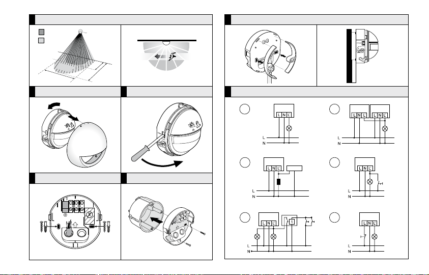
ABB./FIG. 1
1
2.
1.
2
ABB./FIG. 3.2
2,50 m
200°
20 m
ABB ./FIG. 2.1 ABB./FIG. 2 .2
5
m
12
m
ABB./FIG. 4
4.1
4.3
(A)
4.2
4.4
ABB./FIG. 3 ABB./FIG. 3.1
L LN
TOP
TOP
4.5
4.6
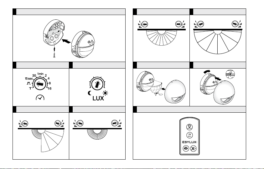
ABB./FIG. 5
1.
2.
ABB./FIG. 7.3 ABB./FIG. 7.4
TOP
2.
ABB ./FIG. 6.1 ABB./FIG. 6.2
AB B./FI G. 7.1 AB B./FI G. 7. 2
12 m2 m
7 m
1.
12 m
ABB./FIG. 8 ABB./FIG. 9
ABB ./FIG. 10
2 m
DE
MONTAGE- UND BEDIENUNGSANLEITUNG
DE
Wir gratulieren Ihnen zum Kauf dieses qualitativ hochwertigen ESYLUX
Produktes. Um ein einwandfreies Funktionieren zu gewährleisten, lesen
Sie bitte diese Bedienungsanleitung sorgfältig durch und bewahren Sie
sie auf, um gegebenenfalls zukünftig nachlesen zu können.
1 • SICHERHEITSHINWEISE
ACHTUNG: Arbeiten am 230 V Netz dürfen nur von autorisiertem
Fachpersonal unter Berücksichtigung der landesüblichen
Installationsvorschriften/-normen ausgeführt werden. Vor der
Montage des Produktes ist die Netzspannung freizuschalten.
Das Gerät ist eingangsseitig mit einem 10 A Leitungsschutzschalter abzusichern.
= Kontaktöffnungsweite < 1,2 mm
μ
Das Produkt ist nur für den sachgemäßen Gebrauch (wie in der
Bedienungsanleitung beschrieben) bestimmt. Änderungen, Modi
fikationen oder Lackierungen dürfen nicht vorgenommen werden,
da ansonsten jeglicher Gewährleistungsanspruch entfällt. Sofort
nach dem Auspacken ist das Gerät auf Beschädigungen zu
prüfen. Im Falle einer Beschädigung darf das Gerät keinesfalls
in Betrieb genommen werden. Wenn anzunehmen ist, dass ein
gefahrloser Betrieb des Gerätes nicht gewährleistet werden kann,
so ist dieses unverzüglich außer Betrieb zu nehmen und gegen
unbeabsichtigten Betrieb zu sichern.
2 • BESCHREIBUNG
ESYLUX Bewegungsmelder sind Passiv-Infrarot-Melder, die
auf sich bewegende Wärmequellen (Personen, Fahrzeuge)
reagieren (Abb. 1 (1) Frontal zum Melder (2) Quer zum
Melder). Erkennt der Bewegungsmelder in seinem
Erfassungsbereich Veränderungen der Wärmestrahlung,
schaltet er in Abhängigkeit des eingestellten Lichtwertes die
angeschlossenen Verbraucher (z. B. Beleuchtung) für eine
einstellbare Dauer ein. Der ESYLUX MD-W200i
Bewegungsmelder ist mit einem Werksprogramm
ausgestattet, bei dem der Melder nach voreingestellten
Werten arbeitet (10 Lux, 2 Min.). Die Werte können
individuell über die Einstellregler am Gerät verändert
werden. Komfortfunktionen sind über die optional erhältliche
Fernbedienung ESYLUX Mobil-RCi-M aktivierbar.
3 • INSTALLATION/MONTAGE/ANSCHLUSS
Bitte beachten Sie vor der Montage folgende Punkte:
-
• Vor der Montage des Produktes ist die
Netzspannung freizuschalten.
• Alle Reichweitenangaben beziehen sich auf eine
Montagehöhe von 2,50 m (Abweichungen führen zur
Veränderung des Erfassungsbereiches).
• Eine optimale Funktion (max. Reichweite) wird erreicht,
wenn die Montage seitlich zur Gehrichtung erfolgt (Abb. 1).
4
• Es ist auf freie Sicht zum Melder zu achten, da Infrarot strahlen keine festen Gegenstände durchdringen können.
• Um den eingebauten Lichtsensor nicht zu beeinflussen, ist
ein Mindestabstand von 1 m zur angeschlossenen
Beleuchtung einzuhalten und Lichtquellen sind nicht direkt
auf den Melder zu richten.
• Berücksichtigen Sie die örtlichen Gegebenheiten, wie
z. B. Nachbargrundstücke/Entfernung zur Strasse.
• Die Montage des Bewegungsmelders sollte nur auf festem,
ebenem Untergrund (Wand) erfolgen.
Entfernen Sie die Abdeckkappe mit einer leichten LinksDrehung (A bb 2.1). Wandsockel und Sensor sind steckbar
miteinander verbunden. Zur Montage beide Teile
voneinander trennen. Schraubendreher in seitliche Öffnung
einsetzen und in Richtung Sensor hebeln, dabei Sensor von
Wandanschlusssockel ziehen (Abb. 2.2). Führen Sie die
Leitung ein und montieren Sie den Wandsockel am
gewünschten Montageort (Abb. 3). Der Lochabstand beträgt
60mm sodass der Wandsockel auf viele europäische
Einbaudosen passt (Abb. 3.1).Bei Aufputz-Leitungseinführung
beachten Sie Abb. 3.2.
Schließen Sie den Bewegungsmelder laut Schaltbild an (Abb. 4).
ACHTUNG: Bei Anschluss an Kapazitiven Lasten wie z.B. EVG
oder parallel kompensierte Leuchtstoff-Lampen sind die
maximalen Einschaltströme zu beachten.
(4.1) Standard Betrieb.
(4.2) Parallelschaltung von max. 8 Geräten.
(4.3) Bei Schaltung von Induktivitäten (z. B. Relais, Schütze,
Vorschaltgeräte) kann der Einsatz eines Löschgliedes
(A) erforderlich sein.
(4.4) Standardbetrieb mit zusätzlicher Dauerfunktion durch
externen Schalter.
(4.5) Parallelschaltung mit Treppenlichtautomat.
(4.6) Standardbetrieb mit der zusätzlichen Möglichkeit des
Einschaltens von Hand.
Sensor auf den Wandsockel stecken bis er einrastet und mit
Sicherungsschraube befestigen (Abb. 5).
Hinweis: Der Bewegungsmelder muss immer so befestigt
sein, dass der Sensor nach vorn und unten zeigt.
4 • INBETRIEBNAHME UND EINSTELLUNGEN
Nach erfolgter Montage und Aufschalten der Netzspannung
führt das Gerät einen ca. 60 Sek. dauernden Selbstprüfzyklus
durch, der durch Blinken der Focus-LED und Einschalten des
angeschlossenen Verbrauchers (optional abschaltbar siehe
Funktionsbeschreibung „RELAIS AUS“ während des
Selbstprüfzyklus) signalisiert wird. Nach Ablauf dieser
Periode ist das Gerät sofort betriebsbereit und arbeitet im
Werksprogramm (10 Lux, 2 min).
Hinweis: Die Fun ktion „RELAIS AUS“ wäh rend des Selbstprüfz yklus
ist werksseitig deaktiviert. Die Aktivierung kann nur während
des Selbstprüfzyklus erfolgen.
DE
5

Testbetrieb
Die Einstellelemente für Nachlaufzeit- und Lichtwert befinden
DE
sich hinter der Abdeckkappe. Stellen Sie das Einstellelement
Nachlaufzeit (Abb. 6.1) auf T für Test. Während des Testbetriebes wird bei jeder erkannten Bewegung, unabhängig von
der Umgebungshelligkeit der Verbraucher 1 Sek. EIN- und 2
Sek. AUS-Geschaltet.
Für die Anpassung des Erfassungsbereiches an die örtlichen
Gegebenheiten stehen Ihnen folgende Möglichkeiten zur
Verfügung:
• Reichweitenregulierung linkes und rechtes Sensorfeld durch
mechanische Verstellung der Internen Linsenmaske (Abb. 7).
• Verwendung der beiliegenden Linsenmaske zur gezielten
Ausblendung von Bereichen (Abb. 8).
Ist der Erfassungsbereich festgelegt, drehen Sie das Einstellelement Nachlaufzeit auf die gewünschte Einschaltdauer (A bb. 6.1)
(Impuls, 15 Sek. bis 16 Min.) und den Lichtwert (Abb. 6.2)
(2 - 2000 Lux) entsprechend den Erfordernissen ein. Impuls
bedeutet eine Einschaltdauer von ca. 1 Sek., worauf eine
Pausenzeit von ca. 9 Sek. folgt, in der keine Bewegungen
erkannt werden.
HINWEIS: Wird beim Drehen des Lichtwert-Reglers (ausgehend vom Mond-Symbol) der aktuelle Umgebungslichtwert
erreicht oder überschritten, wird dies durch das Aufleuchten
der Focus- LED angezeigt (LED ist somit Einstellhilfe). Die LED
erlischt nach 2 Sek. automatisch. In Abhängigkeit vom
eingestelltem Lichtwert und erkannter Bewegung blinkt die
Focus-LED 2 mal. Zusätzlich schaltet der Bewegungsmelder
entsprechend der eingestellten Einschaltdauer den Verbraucher ein. Setzen Sie die Abdeckkappe auf den Sensor
und arretieren ihn mit einer leichten Rechts-Drehung (Abb. 9).
5 • FERNBEDIENUNG
Sämtliche Eingaben per Fernbedienung werden dauerhaft
gespeichert. Bei Stromausfall bleiben die Werte erhalten.
Mit der Fernbedienung Mobil-RCi-M (Ab b. 10) können Sie die
Einstellungen bequem vom Boden aus, ohne Leiter und
Werkzeug vornehmen. Für einen optimalen Empfang richten
Sie die Fernbedienung bei der Programmierung auf den
Bewegungsmelder. Bitte beachten Sie, dass bei direkter
Sonneneinstrahlung die Standardreichweite von ca. 6 m
bedingt durch den Infrarotanteil der Sonne stark reduziert
werden kann.
Quittierung von Sendebefehlen am Gerät
Befehl wurde verstanden und ausgeführt. Focus-LED blinkt
3 mal.
6
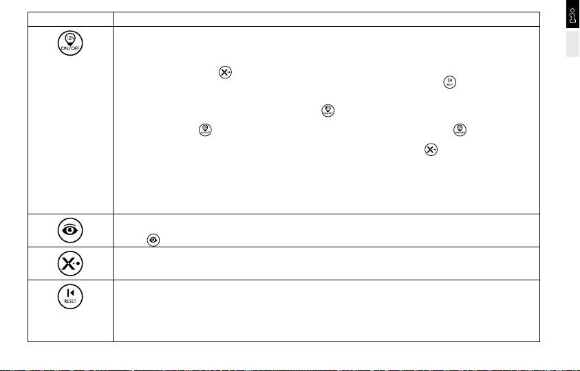
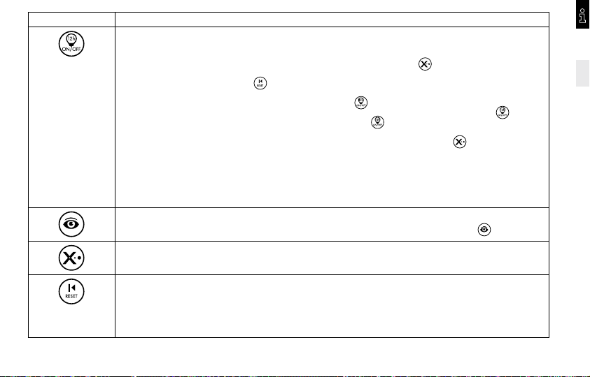
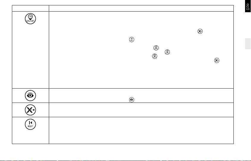
Taste Funktionsbeschreibung
Dauerlicht EIN/AUS
• Verbraucher unabhängig von Bewegung und Umgebungshelligkeit für max. 12 Std. EIN bzw. AUS schalten.
• Hinweis: Die Funktion Dauerlicht AUS ist aus Gründen des Sabotageschutzes werksseitig deaktiviert. Die
Aktivierung kann nur während des Selbstprüfzyklus erfolgen. Dazu Netzspannung aufschalten und während des
Selbstprüfzyklus die Taste
• Zur Deaktivierung dieser Funktion drücken Sie während des Selbstprüfzyklus die Taste
(Rücksetzung in den Auslieferzustand)
Bedienung von Dauerlicht EIN/AUS
• Dauerlicht AUS deaktiviert – Jede Betätigung der Taste
• Dauerlicht AUS aktiviert – Erstmaliges Betätigen der Taste schaltet das Licht für 12 Std. EIN. Erneutes
Betätigen der Taste
im Wechsel AUS – EIN – AUS – EIN...
• HINWEIS: Nach Ablauf der 12 Std. Dauer EIN/AUS oder Abbruch durch die Taste
den Automatikbetrieb.
„RELAIS AUS“ während des Selbstprüfzyklus
• Für den Einsatz an Treppenlichtautomaten in Verbindung mit der Impuls Zeiteinstellung.
• Dazu Netzspannung aufschalten und während des Selbstprüfzyklus die Taste (12 h on/off) drücken.
Die Funktion „RELAIS AN“ während des Selbstprüfzyklus ist jetzt deaktiviert.
• Zur Reaktivierung dieser Funktion drücken Sie während des Selbstprüfzyklus die Taste (12 h on/off).
Einlesen des aktuellen Lichtwertes
• Liest den aktuellen Lichtwert ein. Dieser wird durch Drehen des Lux-Reglers oder erneutes Drücken der
Taste
Abbru ch der Nachlaufzeit / 12h EIN/AUS
Reset
• Abbruch der Nachlaufzeiten. Beendet Dauerlicht EIN/AUS.
Reset – Während des Selbstprüfzyklus (Nach Spannungsunterbrechung)
• Zurücksetzen in den Auslieferungszustand. Löscht alle per Fernbedienung eingegebenen Werte und setzt alle
Funktionen zurück. Das Gerät arbeitet nach seinem voreingestelltem Werksprogramm (10 Lux/2 Min.).
Hinweis: Soll die Dauerlicht AUS Funktion weiterhin genutzt werden, muss diese erneut aktiviert werden.
überschrieben.
drücken. Die Funktion Dauerlicht AUS ist jetzt aktiviert.
schaltet das Licht für 12 Std. EIN.
schaltet das Licht 12 Std. AUS. Wiederholtes Betätigen der Taste schaltet das Licht
.
schaltet der Melder in
DE
7

6 • PRAKTISCHE TIPPS
DE
• Ungewolltes Einschalten kann z. B. durch Kleintiere oder
durch vom Wind bewegte Bäume/Büsche im
Erfassungsbereich ausgelöst werden.
• Durch frontales Bewegen auf den Melder zu, kann die
Reichweite stark verkürzt werden.
7 • ENTSORGUNG
HINWEIS: Dieses Gerät darf nicht mit dem unsortierten
Siedlungsabfall entsorgt werden. Besitzer von Altgeräten sind
gesetzlich dazu verpflichtet, dieses Gerät fachgerecht zu
entsorgen. Informationen erhalten Sie von Ihrer
Stadt- bzw. Gemeindeverwaltung.
8 • ESYLUX HERSTELLERGARANTIE
ESYLUX Produkte sind nach geltenden Vorschriften geprüft
und mit größter Sorgfalt hergestellt. Der Garantiegeber, die
ESYLUX Deutschland GmbH, Postfach 1840, D-22908
Ahrensburg (für Deutschland) bzw. der entsprechende
ESYLUX Distributor in Ihrem Land (eine vollständige Übersicht
finden Sie unter www.esylux.com) übernimmt für die Dauer
von drei Jahren ab Herstelldatum eine Garantie auf
Herstellungs-/Materialfehler der ESYLUX Geräte.
Diese Garantie besteht unabhängig von Ihren gesetzlichen
Rechten gegenüber dem Verkäufer des Geräts.
Die Garantie bezieht sich nicht auf die natürliche Abnutzung,
Veränderung/Störung durch Umwelteinflüsse oder auf
Transportschäden sowie nicht auf Schäden, die infolge
Nichtbeachtung der Bedienungsanleitung, der
Wartungsanweisung und/oder unsachgemäßer Installation
entstanden sind. Mitgelieferte Batterien, Leuchtmittel und
Akkus sind von der Garantie ausgeschlossen.
Die Garantie kann nur gewährt werden, wenn das
unveränderte Gerät unverzüglich nach Feststellung des
Mangels mit Rechnung/Kassenbon sowie einer kurzen
schriftlichen Fehlerbeschreibung, ausreichend frankiert und
verpackt an den Garantiegeber eingesandt wird.
Bei berechtigtem Garantieanspruch wird der Garantiegeber
nach eigener Wahl das Gerät in angemessener Zeit
ausbessern oder austauschen. Weitergehende Ansprüche
umfasst die Garantie nicht, insbesondere haftet der
Garantiegeber nicht für aus der Fehlerhaftigkeit des Geräts
entstehende Schäden. Sollte der Garantieanspruch nicht
gerechtfertigt sein (z.B. nach Ablauf der Garantiezeit oder bei
Mängeln außerhalb des Garantieanspruchs), so kann der
Garantiegeber versuchen, das Gerät kostengünstig gegen
Berechnung für Sie zu reparieren.
8
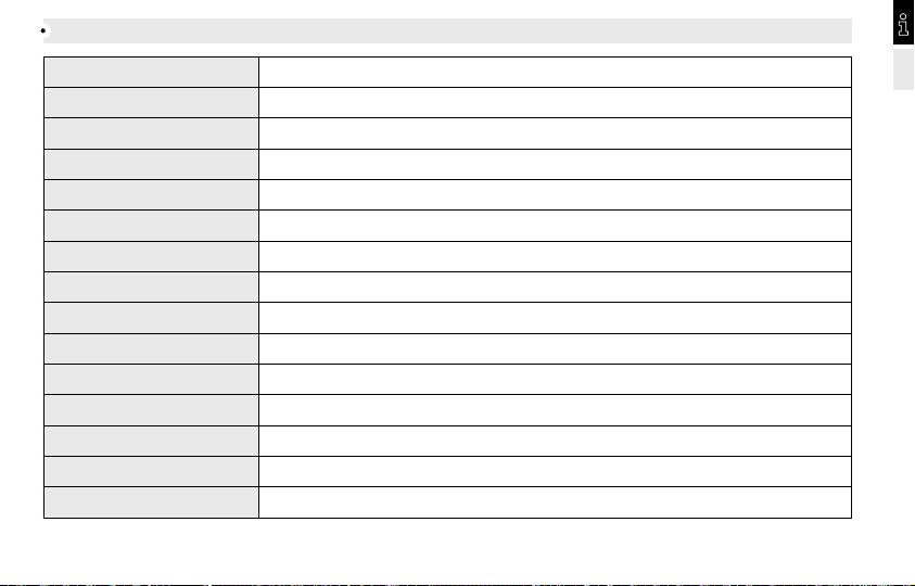
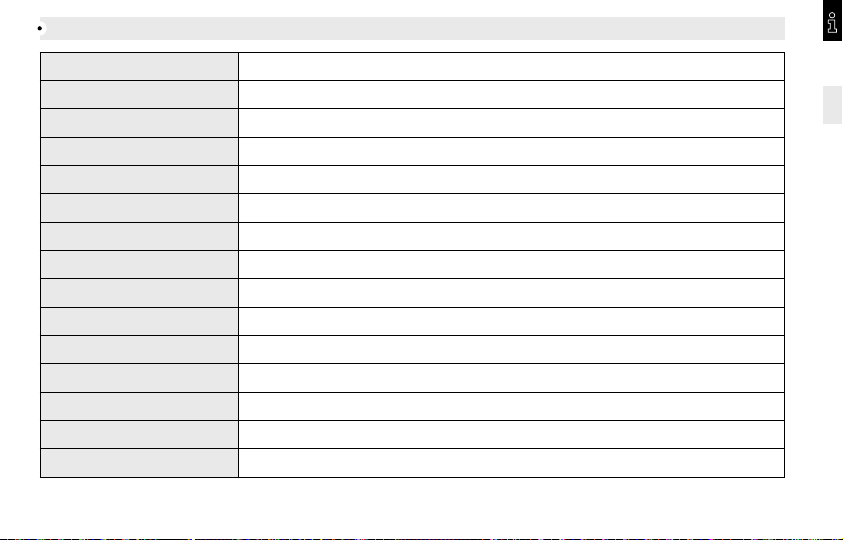
TECHNISCHE DATEN
NETZSPANNUNG 230 V ~ 50 Hz
LEISTUNGSAUF NAHME IN W ca. 0,33
ERFASSUNGSBEREICH 200° (2 x 10 0° separat ei nstellbar)
REICHWEITE ca. 12 m, bei ei ner Montagehöhe von 2 ,50 m
EINSTELLUNGEN Mechanisch über Einstellregler, elektronisch mit Infrarot-Ferbedienung
SCHALTLEISTUNG
MAX. EINSCHALTSTROM 450A/200μs
ZEITEINSTELLUNG ca . 15 Sek. - 16 Min.
LICHTWERT CA. 2 - 2000 L ux
SCHUTZART, SCHUTZKLASSE IP 55, II
PRÜFZEICHEN TÜV/SÜD
BETRIEBSTEMPERATURBEREICH -25 °C ... +55 °C
GEHÄUSE UV-stabilisiertes Polycarbonat
FARBEN weiß, ähnlich RAL 9010, schwarz, ähnlich RAL 9005
ABMESSUNGEN Ø 110 mm, Tiefe: 55 m m
Technische und optische Änderungen ohne Ankündigung vorbehalten
230 V ~ 50 Hz , 2300 W/10 A (cos j = 1), 1150 VA/5 A (co s j = 0,5)
DE
9
GB
INSTALLATION AND OPERATING INSTRUCTIONS
2 • DESCRIPTION
Congratulations on your purchase of this high-quality ESYLUX product.
To ensure proper operation, please read these user instructions carefully
GB
and keep them for future reference.
1 • SAFE TY INSTRUCTIONS
CAUTION: Work on the 230 V power system must be carried out
by authorised personnel only with due regard to the applicable
installation regulations. Switch off the power supply before
installing the system.
On the input side, the device is to be protected against short
circuits with a 10-A circuit breaker.
= Contact gap < 1.2 mm
μ
Use this product only as intended (as described in the user
instructions). Changes or modifications to the product or
painting it will result in loss of warranty. You should check the
device for damage immediately after unpacking it. If there is
any damage, you should not install the device under any
circumstances.
If you suspect that safe operation of the device cannot be
guaranteed, you should turn the device off immediately and
make sure that it cannot be operated unintentionally.
ESYLUX motion detectors are passive infrared detectors
which react to moving heat sources (e.g. people or vehicles)
(fig. 1 (1) head-on to detector (2) diagonally to detector). If
the motion detector senses a change in thermal radiation
inside its field of detection, depending on the set light value,
it will activate the connected system (e.g. an automatic
floodlight) for a preset length of time.
The ESYLUX MD-W200i motion detector features factory
settings and the detector operates according to preset values
(10 lux, 2 min.). The values can be individually modified. The
device can be preset using either the settings on the device
or, more conveniently, using the ESYLUX Mobil-RCi-M remote
control (available as an option).
3 • INSTALLATION/ASSEMBLY/CONNECTION
Before installing the device, observe the following:
• Turn off the power supply.
• Information concerning range is based on an installation
height of 2.50 m (the field of detection will vary
according to this height).
• For optimum performance (i.e. maximum range), position
the device so that people/vehicles are moving parallel to
the detector (fig. 1).
• Make sure that the detector has a clear line of sight, as
infrared beams cannot penetrate solid objects.
10
• To avoid influencing the light sensor, maintain a minimum
distance of 1 m in relation to the connected lighting and
do not point light sources directly at the detector.
• When installing the device, bear in mind the surrounding
area e.g. neighbouring properties or the distance to the road.
• The motion detector should only be installed on a stable,
flat surface (wall).
Remove the covering cap by turning it slightly to the left (fig. 2.1).
The wall base unit and sensor are connected. For installation
purposes, separate the two parts. Fit the screwdriver into the
side opening, lever in the direction of the sensor and pull the
detector away from the wall connector base (fig. 2.2). Feed
the cable into the detector and mount the wall base unit in
the required position (fig. 3). The hole distance is 60 mm so
that the wall base can also be mounted on standard
recessed-mounted boxes (fig. 3.1). For surface-mounted
boxes, refer to fig. 3.2.
Connect the motion detector according to the circuit
diagram (fig. 4).
CAUTION: The maximum inrush current must not be exceeded
when connecting to capacitive loads such as electronic ballasts
or fluorescent lamps with parallel compensation.
(4.1) Standard operation.
(4.2) Parallel connection of max. 8 devices.
(4.3) When connecting inductors (e.g. relays, contactors,
ballasts) the use of a filter (A) may be necessary.
(4.4) Standard operation with additional continuous function
through external switches.
(4.5) Parallel connection with automatic stairwell light.
(4.6) Standard operation with the additional possibility of
switching on by hand.
Press the sensor into the wall base until it clicks into place
and secure it with the safety screw (fig. 5).
NB: The motion detector must always be mounted so that the
sensor faces forwards and downwards.
4 • START-UP AND SETTINGS
After the device has been successfully installed and the
power supply switched on, the device will perform a self-test
(lasting about 60 seconds). During this test, the focus LED will
flash and the connected system (can be switched off
optionally – see p. 13) will come on. Once this time has
elapsed, the device will be operational and will function
according to the factory settings (10 lux, 2 min).
Note: to prevent tampering, the ”Relay OFF du ring the self-test”
is disabled in the factory settings. Activation is only possible
during the self-test.
11
GB

Test m ode
The time setting and light value switches are located behind
the covering cap. Set the time setting switch (fig. 6.1) to T for
test. During test mode, irrespective of ambient brightness, if
GB
motion is detected, the system will switch ON for 1 second
and OFF for 2 seconds.
The following possibilities are available to adjust the field of
detection to the surrounding area:
• Adjust the range on the left and the sensor field on the right
by mechanically adjusting the internal lens mask (fig. 7).
• Use the supplied covering cap to mask specific areas (fig. 8).
Once you have established the field of detection, turn the
time setting switch to the required ON period (fig. 6.1)
(Impulse 15 seconds - 16 minutes) and adjust the light value
(fig. 6.2) (2 - 2000 lux) according to your requirements.
Impulse means that the device is activated for 1 second
followed by a break of 9 seconds in which no movement is
detected.
NOTE: When turning the light value switch (starting from the
moon symbol), if the current ambient brightness is reached or
exceeded, the focus LED will light up (as a setting aid). The
LED automatically goes out after 2 seconds. Depending on
the set light value and any detected movement, the focus LED
will flash twice. The motion detector also switches the system
on according to the set ON period. Place the covering cap
on the sensor and lock it by turning it gently to the right (fig. 9).
5 • REMOTE CONTROL
All settings programmed by remote control are permanently
stored in the memory and will not be lost in the event of a
power failure.
Using the remote control Mobil-RCi-M (fig. 10) the settings
can be easily programmed without needing to climb a
ladder or use any tools. For optimum reception, when
programming the settings, point the remote control at the
motion detector. Please note that if the sun shines directly on
the sensor, the standard detection range of approx. 6 m may
be dramatically reduced owing to the sun’s infrared rays.
Acknowledgement of commands
If the command is acknowledged and performed: Focus LED
flashes 3 times.
6 • PRAC TICAL ADVICE
• Small animals, nearby trees or bushes moving in the wind
may cause the floodlight to switch on.
• The detector‘s range can be dramatically reduced by
objects moving towards it, rather than parallel with it.
12
Button Operating the device
Continuous lighting ON/OFF
• System can be switched ON or OFF, independently of motion or ambient brightness, for 12 hours max.
• NB: To prevent tampering, the continuous lighting OFF function is disabled in the factory settings. Activation
is only possible during the self-test. Switch the power supply on and press the
The continuous light OFF function is now enabled.
• To disable this function, press the
Operating continuous light mode ON/OFF
• Continuous light mode OFF disabled – Every time the button
• Continuous light OFF enabled – Pressing the button once switches the light ON for 12 hours. If the
is pressed again, the light will switch OFF for 12 hours. Press the
OFF – ON – OFF – ON.
• NOTE: After the maximum 12-hour „Permanent ON/OFF“ period has expired, or if the
the detector will switch to Automatic mode.
”RELAY OFF“ during the self-test
• For use on automatic stairwell lights in connection with impulse time setting.
• Switch the power supply on and press the (12h on/off) button during the self-test. The ”RELAY ON“ during the
self-test function is now disabled.
• To reactivate this function, press the (12h on/off) button during the self-test.
Storing the current light intensity value
• Stores the current light intensit y value. To overwrite this value, turn the LUX switch or press the
Cancels the time settings / 12 hours ON/OFF
Reset
• Cancels the time settings. Exits continuous lighting ON/OFF.
Reset – During the self-test (after switching the power off).
• Resets the device to the default settings. Cancels all values set by remote control and resets all functions.
The device operates according to the preset factory settings (10 lux/2 min.).
NB: If the Continuous light OFF function is used further, it must be re-enabled.
button during the self-test.
button during the self-test. (Resets factory settings).
is pressed, the light switches ON for 12 hours.
button again to switch the light
GB
button
button is pressed,
button again.
13

7 • DISPOSAL
NOTE: this device must not be disposed of as unsorted
household waste. Used devices must be disposed of correctly.
GB
Contact your local town council for more information.
8 • ESYLUX MANUFACTURER’S GUARANTEE
ESYLUX products are tested in accordance with applicable
regulations and manufactured with the utmost care. The
guarantor, ESYLUX Deutschland GmbH, Postfach 1840,
D-22908 Ahrensburg, Germany (for Germany) or the
relevant ESYLUX distributor in your country (visit www.esylux.
com for a complete overview) provides a guarantee against
manufacturing/material defects in ESYLUX devices for a period
of three years from the date of manufacture.
This guarantee is independent of your legal rights with respect
to the seller of the device.
The guarantee does not apply to natural wear and tear,
changes/interference caused by environmental factors or
damage in transit, nor to damage caused as a result of failure
to follow the user or maintenance instructions and/or as a result
of improper installation. Any illuminants or batteries supplied
with the device are not covered by the guarantee.
The guarantee can only be honoured if the device is sent back
with the invoice/receipt, unchanged, packed and with sufficient
postage to the guarantor, along with a brief description of the
fault, as soon as a defect has been identified.
If the guarantee
claim proves justified, the guarantor will, within a reasonable
period, either repair the device or replace it. The guarantee
does not cover further claims; in particular, the guarantor
will not be liable for damages resulting from the device’s
defectiveness. If the claim is unfounded (e.g. because the
guarantee has expired or the fault is not covered by the
guarantee), then the guarantor may attempt to repair the
device for you for a fee, keeping costs to a minimum.“
14
TECHNICAL DATA
MAIN S VOLTAGE 230 V ~ 50 Hz
POWE R CONSUMP TION IN W approx. 0,33
FIEL D OF DETEC TION 200° (2 x 100° can be s et independ ently)
RANGE approx . 12 m at an ins tallation he ight of 2.50 m
SETTIN GS Mechanically using the setting controls, electronically using the infrared remote control
SWIT CHING CA PACITY
MAX INRUSH CURRENT 450A/200μs
TIME SETTING approx. 15 sec. - 16 min .
APPR OX. LIGHT VAL UE 2 - 2000 l ux
PROTECTION TYPE, PROTECTION CLASS IP 55, II
TES T SYMBOL TÜV/SÜD
OPER ATING TE MPERATU RE RANGE -25 °C ... +55 °C
HOUSI NG UV stabilised polycarbonate
COLOURS white, similar to RAL 9010, black, similar to RAL 9005
MEASUREMENTS Ø 110 mm, depth: 55 mm
Technical and design features may be subject to change
230 V ~ 50 Hz , 2300 W/10 A (cos j = 1), 1150 VA/5 A (co s j = 0,5)
GB
15
FR
NOTICE DE MONTAGE ET D’UTILISATION
Félicitations ! Avec ce produit ESYLUX, vous avez fait le choix de
la qualité. Pour l’utiliser dans les meilleures conditions, veuillez
lire attentivement ce mode d’emploi et le conserver en vue d’une
consultation future.
FR
1 • CONSIGNES DE SÉCURITÉ
ATTENTION: Seules des personnes autorisées et qualifiées pour
effectuer une installation conforme aux normes et prescriptions
en vigueur peuvent intervenir sur le réseau 230 V. Coupez le
courant avant d’installer le produit.
L’appareil doit être protégé côté entrée à l’aide d’un
disjoncteur 10 A.
= Ouverture de contact < 1,2 mm
μ
Ce produit ne doit être utilisé que dans les conditions prévues
par le présent mode d’emploi. Toute modification du produit
(ajout, peinture, etc.) entraîne l’annulation de la garantie.
Une fois que vous avez déballé l’appareil, vérifiez qu’il ne
présente aucun défaut. En cas d’anomalie, ne le mettez pas
en marche.
Si vous n’êtes pas certain que l’appareil peut être utilisé en
toute sécurité, éteignez-le immédiatement et prenez vos
dispositions pour empêcher toute utilisation involontaire.
2 • DESCRIPTION
Il s‘agit de détecteurs à infrarouge passif réagissant aux
sources de chaleur en mouvement (personnes, voitures) (fig. 1
(1) Déplacement face au détecteur (2) Déplacement latéral
par rapport au détecteur). Lorsque le détecteur de
mouvement repère une modification du rayonnement
thermique au sein de sa zone de détection, si la luminosité a
atteint le seuil programmé, il active les appareils électriques
qui lui sont raccordés (par exemple, des luminaires) pendant
la durée préalablement programmée par l‘utilisateur. Le
détecteur ESYLUX MD-W200i est doté d‘un programme
offrant des pré-réglages d‘usine (10 lux/2 minutes). Ces
valeurs peuvent être modifiées individuellement, par
l‘intermédiaire de l‘un des deux modes de réglage proposés:
soit à même l‘appareil, soit, plus simplement, au moyen de la
télécommande ESYLUX Mobil-RCi-M disponible en option.
3 • INSTALLATION/MONTAGE/RACCORDEMENT
Avant de procéder au montage, prenez connaissance des
instructions ci-après :
• Avant d‘installer le produit, coupez le courant.
• Toutes les indications de portée sont fournies sur la base
d‘une hauteur de montage de 2,5 m (la zone de détection
varie en fonction de cette hauteur).
• Pour des performances optimales, c‘est-à-dire une portée
maximale, montez le détecteur perpendiculairement au
sens de la marche (fig. 1).
16
• L‘espace situé devant le détecteur doit être dégagé car les
rayons infrarouges ne traversent pas les objets.
• Afin de ne pas perturber le capteur photosensible intégré,
une distance minimale de 1 m doit être respectée entre le
détecteur et le luminaire raccordé. En outre, aucune source
lumineuse ne doit être directement orientée vers le détecteur.
• Étudiez bien le milieu d‘installation en prenant garde, par exemple,
à la proximité éventuelle d‘une rue ou de terrains voisins.
• Montez le détecteur de mouvement sur une surface murale
solide et plane.
Retirez le capuchon en tournant légèrement vers la gauche
(fig. 2.1). Le socle mural et le capteur sont emboîtables.
Cependant, lors du montage, ils doivent être séparés.
Insérez un tournevis dans la rainure située sur le côté et
ramenez-le latéralement vers le capteur tout en éloignant
celui-ci du socle mural (fig. 2.2). Introduisez le câble et fixez
le socle mural à l‘emplacement souhaité (fig. 3). La distance
entre les trous de fixation est de 60 mm, ce qui permet
également de fixer le socle mural sur des boîtiers encastrés
standard (fig. 3.1). Dans le cas d‘une entrée de câbles
apparente, référez-vous aux fig. 3.2.
Raccordez le détecteur de mouvement conformément au
schéma électrique (fig. 4).
ATTENTION : lorsque vous raccordez des charges capacitives
telles que des ballasts électroniques ou des ampoules
fluorescentes compensées en parallèle, tenez compte du
courant d‘appel maximal.
(4.1) Installation standard.
(4.2) Montage en parallèle de 8 appareils max.
(4.3) Le branchement d‘inductances (par ex. relais,
contacteur, ballast) peut nécessiter l‘insertion d‘un
circuit RC (A).
(4.4) Installation standard avec fonction d‘éclairage
permanent contrôlée par interrupteur externe.
(4.5) Montage en parallèle avec minuterie d‘escalier.
(4.6) Installation standard + possibilité d‘allumage manuel.
Emboîtez le capteur sur le socle mural et fixez-le à l‘aide de
la vis de blocage (fig. 5).
Remarque : le détecteur de mouvement doit toujours être fixé
de façon à ce que le capteur soit orienté vers l‘avant et vers
le bas.
4 • MISE EN SERVICE ET RÉGLAGES
Une fois installé et raccordé, le capteur lance un cycle de
test de 60 secondes environ : pendant cette opération, la
LED de repérage clignote et l‘appareil raccordé s‘active
(possibilité de désactivation, voir page 19). Une fois le test
terminé, l‘appareil est prêt à l‘emploi et fonctionne avec les
pré-réglages d‘usine (10 lux/2 minutes).
Remarque : la fonction „ Désactivation des relais“ pendant le
cycle de test est désactivée en usine (mesure anti-vandalisme)
et ne peut être activée que pendant le cycle de test.
FR
17

Mode test
Les éléments de réglage de la durée d‘allumage et de la
luminosité se situent derrière le capuchon. Positionnez l‘élément
de réglage de la durée d‘allumage (fig. 6.1) sur T pour Test. En
mode Test, chaque mouvement détecté entraîne sur l‘appareil
une alternance 1 s d‘activation/2 s de désactivation, quelle que
FR
soit la luminosité ambiante. Vous disposez de plusieurs solutions
pour adapter la zone de détection au milieu d‘installation:
• Ajustement de la portée gauche et droite du capteur par
réglage mécanique de l‘obturateur de lentille interne (fig. 7).
• Utilisation du capuchon de lentille fourni pour neutraliser
certaines zones (fig. 8).
Une fois la zone de détection déterminée, positionnez l‘élément
de réglage de la durée d‘allumage sur la durée souhaitée (fig. 6.1)
(mode impulsions,15 s à 16 min) et réglez la luminosité (fig. 6.2)
(2 à 2000 lux) en fonction de vos besoins. Le mode impulsions
correspond à une durée d‘activation de 1 seconde, suivie d‘une
phase d‘interruption de 9 secondes au cours de laquelle plus
aucun mouvement n‘est détecté.
REMARQUE: Si, en réglant la luminosité (en partant du symbole
"lune"), vous atteignez ou dépassez la luminosité ambiante
actuelle, la LED de repérage s‘allume (aide au réglage). La LED
s‘éteint automatiquement au bout de 2 s. Si la luminosité atteint
le seuil programmé ou si un mouvement est repéré dans la zone
de détection, la LED de repérage clignote à 2 reprises. En
outre, le détecteur de mouvement allume le luminaire pour la
durée programmée. Replacez le capuchon sur le capteur et
verrouillez-le en tournant légèrement vers la droite (fig. 9).
5 • TÉLÉCOMMANDE
Toutes les données saisies à l‘aide de la télécommande sont
stockées en mémoire, ce qui permet de les conserver même
en cas de panne de courant.
La télécommande Mobil-RCi-M (fig. 10) vous permet
d‘effectuer vos réglages depuis le sol, sans échelle ni outil.
Pour une transmission optimale lors de la programmation,
orientez la télécommande en direction du détecteur de
mouvement. Attention : en cas d‘ensoleillement direct du
dispositif, la portée standard (6 m) peut être fortement
diminuée par le rayonnement infrarouge du soleil.
Acquittement des indications transmises à l‘appareil
Indication comprise et prise en compte : la LED de repérage
clignote 3 fois.
6 • CONSEILS PRATIQUES
• De petits animaux ou le souffle du vent dans les arbres ou
buissons situés dans la zone de détection peuvent
entraîner une activation intempestive du luminaire.
• La portée du détecteur est fortement amoindrie lorsque le
sujet se déplace face à lui.
18
Touches Fonctions
Allumage/Extinction permanente
• Allumage ou extinction du luminaire indépendamment des mouvements et de la luminosité perçus pour une durée
de 12 heures.
• Remarque : la fonction "Extinction permanente" est désactivée en usine (mesure anti-vandalisme) et ne
peut être réactivée que pendant le cycle de test. Pour ce faire, allumez l‘appareil et appuyez sur pendant le cycle
de test. La fonction "Extinction permanente" est alors activée.
• Pour désactiver cette fonction, appuyez sur la touche pendant le cycle de test (rétablissement des paramètres par défaut).
Utilisation des fonctions Allumage/Extinction permanente
• Fonction "Extinction permanente" désactivée : tout appui sur la touche allume l‘éclairage pendant 12 h.
• Fonction "Extinction permanente" activée : un premier appui sur la touche allume l‘éclairage pendant 12 h, et un
second appui l‘éteint pendant 12h. Un nouvel appui sur la touche entraîne une alternance extinction/allumage.
• REMARQUE : au terme des 12 heures d‘"Allumage/Extinction permanente" ou en cas d‘appui sur la touche , le
détecteur passe en mode automatique.
”Désactivation des relais“ pendant le cycle de test
• S‘utilise pour les minuteries d‘escalier, en combinaison avec le réglage de la durée par impulsion.
• Pour ce faire, allumez l‘appareil et appuyez sur la touche (12h on/off) pendant le cycle de test. La fonction
Relais activés pendant le cycle de test est désormais désactivée.
• Pour réactiver cette fonction, appuyez sur la touche (12h on/off) pendant le cycle de test.
Saisie a utomatique d e la luminosi té en cours
• Enregistre la valeur de la luminosité en cours. Pour effacer cette valeur, il suffit de tourner la molette de réglage de la
luminosité ou d‘appuyer de nouveau sur la touche .
Interruption d e l'éclairage / A llumage/Exti nction 12h
Réinitialisation
• Interruption de l‘éclairage. Met fin à l‘allumage/extinction permanente.
Réinitialisation – Pen dant le cycle de test (après coupure de cour ant)
• Rétablissement des paramètres par défaut de l‘appareil. Supprime tous les réglages effectués par la télécommande et
réinitialise toutes les fonctions. Le détecteur utilise ses pré-réglages d‘usine (10 lux/2 minutes).
Remarque : si vous souhaitez continuer d‘utiliser la fonction "Extinction permanente", vous devez la réactiver.
FR
19

7 • RECYCLAGE
REMARQUE : cet appareil ne doit en aucun cas être jeté avec
les déchets municipaux. Les propriétaires d‘équipements
électriques ou électroniques usagés ont en effet l‘obligation
légale de les déposer dans un centre de collecte sélective.
FR
Informez-vous auprès de votre municipalité sur les possibilités
de recyclage.
8 • ESYLUX - GARANTIE DU CONSTRUCTEUR
Les produits ESYLUX sont fabriqués avec le plus grand soin et
testés selon les normes en vigueur. Le garant, ESYLUX
Deutschland GmbH, Case postale 1840, D-22908
Ahrensburg (pour l’Allemagne) ou le distributeur de la
marque dans votre pays (vous trouverez toutes les
informations nécessaires à ce sujet sur le site www.esylux.
com) garantit les appareils ESYLUX contre les défauts de
fabrication et de matériaux pour une durée de 3 ans à partir
de la date d’achat.
Cette garantie est indépendante de vos droits légaux
vis-à-vis du vendeur de l’appareil.
L’usure naturelle, les modifications de l’appareil dues à son
milieu d’installation et les dommages résultant de son
transport n’entrent pas dans le cadre de la garantie. De
même, ne sont pas couverts les défauts dus au non-respect
des instructions de montage et d’entretien et/ou à une
installation inappropriée. Sont également exclues de la
garantie les batteries, sources lumineuses et piles fournies
avec l’appareil.
La procédure de garantie ne pourra être enclenchée que sur
présentation d’un appareil non modifié après constatation du
défaut, ainsi que d’un ticket de caisse valable, accompagnés
d’une courte description de l’anomalie constatée et expédié
au garant dans un emballage approprié et suffisamment
affranchi.
Si le recours en garantie s’avère justifié, le garant peut
décider soit de réparer, soit de remplacer l’appareil dans les
meilleurs délais. La garantie ne comprend aucun autre
recours. Le garant n’est notamment pas responsable de tout
dommage causé par un défaut de l’appareil. Si le recours de
garantie s’avère injustifié (par exemple, si la garantie a
expiré ou si le défaut constaté n’est pas couvert par celle-ci),
le garant tentera de réparer l’appareil au meilleur coût.
20

DONNÉES TECHNIQUES
ALIMENTATION 230 V ~ 50 Hz
CONSOMMATION EN W 0,33 e nv.
ZONE DE DÉ TECT ION 200° (2 x 100° réglables séparément)
PORTÉE 12 m env. pour une h auteur de mont age de 2,5 m
RÉGLAGES par molettes ou télécommande infrarouge
PUISS ANCE DE COU PURE
COURANT D’APPEL MAXIMAL 450A/200μs
RÉGL AGE DE LA DUR ÉE 15 s à 16 min env.
LUMINOSITÉ ENV. 2 - 2000 l ux
DEGRÉ D E PROTEC TION, CL ASSE DE PRO TECTI ON IP 55, II
MARQ UE DE CONFOR MITÉ TÜV/SÜD
PLA GE DE TEMPÉ RATURE S DE
FONCTIONNEM ENT
BOÎTIER polycarbonate résistant aux UV
COLORIS blanc, similaire à RAL 9010, noir similaire à RAL 9005
DIMENSIONS Ø 110 mm, profond eur : 55 mm
Des modifications techniques et esthétiques peuvent être apportées sans préavis
230 V ~ 50 Hz , 2300 W/10 A (cos j = 1), 1150 VA/5 A (co s j = 0,5)
-25 °C ... +55 °C
FR
21

NL
INSTALLATIE- EN GEBRUIKERSHANDLEIDING
Wij feliciteren u met de aankoop van dit ESYLUX kwaliteitsproduct.
Deze gebruiksaanwijzing staat borg voor een goede werking.
Lees de handleiding aandachtig en bewaar ze om later eventueel te
kunnen nalezen.
1 • VEILIGHEIDSINSTRUCTIES
NL
LET OP: Werkzaamheden aan het 230V-net mogen uitsluitend
door gekwalificeerd vakpersoneel uitgevoerd worden conform de
geldende installatievoorschriften/-normen. Voor montage van
het product de netspanning uitschakelen.
Het apparaat dient aan ingangszijde met een
installatieautomaat van 10 A te worden gezekerd.
= Contactopening < 1,2 mm
μ
Het product is alleen bestemd voor normaal gebruik (volgens
de gebruiksaanwijzing). Aanpassingen, toevoegingen of
schilderen zijn verboden omdat hierdoor iedere
garantieaanspraak vervalt. U dient het apparaat onmiddellijk
na het uitpakken op beschadigingen te controleren. Bij
beschadiging mag het apparaat in geen geval in gebruik
genomen worden.
Wanneer aannemelijk is dat veilig gebruik niet gewaarborgd
kan worden, dient u het apparaat direct buiten gebruik te
stellen en onbedoeld gebruik ervan te voorkomen.
2 • BESCHRIJVING
ESYLUX bewegingsmelders zijn passief-infraroodmelders die
op bewegende warmtebronnen (personen, voertuigen)
reageren (fig. 1 (1) Recht voor de melder (2) Dwars op de
melder). Signaleert de bewegingsmelder binnen zijn
detectiezone veranderingen in de warmtestraling, dan
schakelt hij, afhankelijk van de ingestelde lichtwaarde, de
aangesloten verbruiker (bijv. verlichting) in voor een instelbare
periode. De ESYLUX MD-W200i bewegingsmelder is voorzien
van een fabrieksprogramma, waarbij de melder werkt op
basis van vooraf ingestelde waarden (10 Lux, 2 min.). Deze
waarden kunnen individueel worden gewijzigd. U kunt het
apparaat op twee manieren instellen: conventioneel via de
regelaars op het apparaat of comfortabel via de optioneel
verkrijgbare afstandsbediening ESYLUX Mobil-RCi-M.
3 • INSTALLATIE / MONTAGE / AANSLUITING
Houd voor montage rekening met het volgende:
• Voor montage van het product de netspanning uitschakelen.
• Alle gegevens met betrekking tot het bereik zijn gebaseerd
op een montagehoogte van 2,50 m (bij afwijking hiervan
zal het bereik wijzigen).
• Een optimale werking (maximaal bereik) wordt behaald
door de melder langs de looprichting te monteren (fig. 1).
• Let erop dat de melder vrij zicht heeft, aangezien
infraroodstraling niet door vaste objecten kan dringen.
22
• Om de ingebouwde lichtsensor niet te beïnvloeden
dient een minimale afstand van 1 m ten opzichte van de
aangesloten verlichting aangehouden te worden en mogen
lichtbronnen niet direct op de melder worden gericht.
• Houd rekening met de plaatselijke omstandigheden, zoals
aangrenzende percelen of een nabijgelegen straat.
• De bewegingsmelder dient alleen op een vaste, vlakke
ondergrond (wand) te worden gemonteerd.
Verwijder de afdekkap door hem linksom los te draaien (fig. 2.1).
De sensor zit in de wandsteun gestoken. Voor montage
moeten beide delen van elkaar worden gehaald. Steek een
schroevendraaier in de zijuitsparing. Breng vervolgens het
handvat naar de sensor en trek daarbij de sensor uit de
aansluitsokkel (fig. 2.2). Voer de bedrading in en bevestig de
wandsteun op de gewenste plaats (fig. 3). De gatafstand
bedraagt 60 mm, zodat de wandsteun ook op standaard
opbouwdozen gemonteerd kan worden (fig. 3.1). Raadpleeg
fig. 3.2 voor kabelinvoer bij opbouwdozen.
Sluit de bewegingsmelder volgens het schakelschema aan (fig. 4).
LET OP: Bij aansluiting op capacitieve lasten zoals EVSA of
parallelgecompenseerde fluorescentielampen dient rekening te
worden gehouden met de maximale inschakelstroom.
(4.1) Standaardmodus.
(4.2) Parallelschakeling van max. 8 apparaten.
(4.3) Bij schakeling van inductoren (bijv. relais,
magneetschakelaars, voorschakelapparatuur) kan een
ontstoringscondensator (A) nodig zijn.
(4.4) Standaardmodus met extra continufunctie via
externe schakelaar.
(4.5) Parallelschakeling met trappenhuisautomaat.
(4.6) Standaardmodus met handmatig inschakelen als
extra mogelijkheid.
De sensor op de wandsteun klikken en met de borgschroef
vastzetten (fig. 5).
Opmerking: De bewegingsmelder moet altijd met de sensor
naar voren en omlaag gericht worden bevestigd.
4 • INSTALLATIE EN INSTELLINGEN
Na succesvolle installatie en inschakeling van de netspanning
voert het apparaat een zelftest van ongeveer 60 seconden uit,
waarbij de focus-LED knippert en de aangesloten verbruiker
aan gaat (optioneel uit te schakelen, zie pagina 25).
Hierna is het apparaat klaar voor gebruik en is het
fabrieksprogramma actief (10 Lux, 2 min).
Opmerking: De ”RELAIS UIT“ tijdens de zelftest is standaard
gedeactiveerd, als bescherming tegen vandalisme. Activering is
alleen mogelijk tijdens de zelftest.
NL
23
 Loading...