

ESYLUX PD-FLAT 360i/6 mini DALI, EP10427503, PD-C 360i/8 mini DALI, EP10427510 Operating Instructions Manual
MA00940001
09/2015
Operating instructions
PD-FLAT 360i/6 mini DALI
EP10427503
PD-C 360i/8 mini DALI
EP10427510
ESYLUX GmbH | An der Strusbek 40
22926 Ahrensburg | Germany
info@esylux.com | www.esylux.com
1

OPERATING INSTRUCTIONS
Table of contents
1 Using the manual 4
2 Safety instructions 4
3 Intended use 4
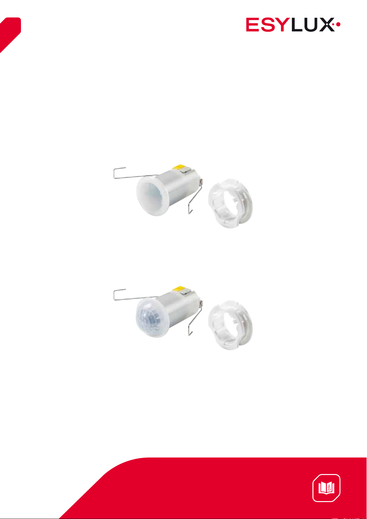
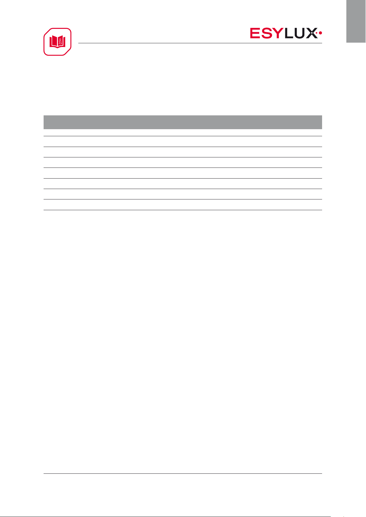
4 Description of the devices 5
5 Included in delivery 5
GB
6 Technical data 6
7 Operating elements 6
8 Maintenance 6
9 Cleaning 7
10 EC Declaration of Conformity 7
11 Activation 7
Installation types 7
Connecting the device 7
Wiring diagram 8
Factory settings 8
12 Operating mode 9
Automatic switch-on 9
Automatic switch-off 9
Switch-off delay time 10
Light value 10
Delay 10
Orientation light 11
PD-FLAT 360i/6 mini DALI
PD-C 360i/8 mini DALI
2 / 20

OPERATING INSTRUCTIONS
Switch-off warning 12
Fully automatic mode 12
Semi-automatic mode 13
100 h burn-in function 13
Corridor function 14
LED feedback 14
Sensitivity 14
Electronic ballast DALI parameters 15
Switch input 15
Master / slave function 16
Twilight switch mode 17
GB
Querying the active mode 18
Reset 18
13 Accessories 19
14 Disposal 20
15 ESYLUX manufacturer's guarantee 20
PD-FLAT 360i/6 mini DALI
PD-C 360i/8 mini DALI
3 / 20

OPERATING INSTRUCTIONS
1 Using the manual
This manual is intended to provide valuable information to you as the user and
integrator on how to use and configure the device and to take full advantage of the
range of functions.
Please store this manual with your documentation for the premises for future
reference so you can find the correct answer if questions arise.
If you have any questions that are still unanswered, please visit our website at
www.esylux.com or contact our technical helpline directly on +49 (0) 4102 489 489.
GB
2 Safety instructions
• CAUTION: Work on the 230 V power system must be performed by authorised personnel
only, with due regard to the applicable installation regulations / standards.
• Switchoffthepowersupply/DALIbusvoltagebeforeinstallingthesystem.
• Observetheapplicablesafetyregulationswhenworkingonelectricalsystems.
3 Intended use
The detector is designed to be connected to DALI systems to automatically control the
switching on or dimming of lighting according to ambient light or when movement /
presence is detected.
PD-FLAT 360i/6 mini DALI
PD-C 360i/8 mini DALI
4 / 20

OPERATING INSTRUCTIONS
4 Device description
The ESYLUX ceiling-mounted presence detector is a passive infrared presence
detector that responds to moving heat sources, such as people walking. The presence
detector is designed for small rooms and passageways that benefit from natural light.
Parameters can be configured using the ESYLUX Mobil-PDi/MDi and Mobil-PDi/MDi
universal remote controls as well as via the manual setting elements.
NOTE: Use this product only as intended (as described in the user instructions). The
device must not be changed, modified or painted – doing so will void any warranty
claims. You must check the device for damage immediately after unpacking it. If there
is any damage, you should not install the device under any circumstances. If you
suspect that safe operation of the device can not be guaranteed, you should turn the
device off immediately and make sure that it cannot be operated unintentionally.
GB
5 Included in delivery
Please check the contents of the delivery immediately after unpacking the device.
1. Presence detector
2. 2 x WAGO micro-terminals
3. Locking ring
4. Spring clamp
5. Screw
6. Tool
7. Holding disc for lens mask (PD-C360i/8 mini DALI only)
8. Lens mask to mask fields of detection (PD-C360i/8 mini DALI only)
PD-FLAT 360i/6 mini DALI
PD-C 360i/8 mini DALI
5 / 20
OPERATING INSTRUCTIONS
6 Technical data
PD-FLAT 360i/6 mini DALI / PD-C 360i/8 mini DALI
GB
Operating voltage DALI 16 V
Contact Max. 0.8 mm 2 / plug-in terminal
Protection type IP 55
Operating temperature range 0 °C to +50 °C
Approx. dimensions H 39 mm / mH 60 mm, Ø 33 mm
Installation bore diameter 25 mm
Communication Broadcast / non-addressable
7 Operating elements
The presence detector has no setting elements. The adjustable parameters can be
configured via remote control.
⎓
8 Maintenance
The presence detector has no serviceable parts.
PD-FLAT 360i/6 mini DALI
PD-C 360i/8 mini DALI
6 / 20

OPERATING INSTRUCTIONS
9 Cleaning
To clean the detector, use a slightly damp, lint-free cloth and normal domestic soap.
Beware of harsh detergents, which can corrode the surface of the detector affecting its
ability to detect movement and light.
10 EC Declaration of Conformity
GB
The CE label corresponds to the following directives:
• EMC 2004/108/EC
• RoHS 2011/65/EU
11 Activation
Installation types
Recessed ceiling mounting. The presence detector is mounted in a false ceiling by
inserting the device into the hole and clamping it in place using either a spring clamp
or locking ring.
Connecting the device
Switch off the DALI bus before connecting the device. The electrical contact is
established using WAGO micro-terminals, each of which can be used to connect up
to five cables with rigid wire ranging from 0.6 mm
For DALI, avoid ring-shaped connection structures as these can cause problems. Other
connection structures are permitted
2
to 0.8 mm 2. Observe the polarity.
PD-FLAT 360i/6 mini DALI
PD-C 360i/8 mini DALI
7 / 20

OPERATING INSTRUCTIONS
Wiring diagram
The max. cable length of the DALI bus cable is 300 m
when using 1.5 mm
Laying the DALI bus in combination with the mains cable
is not recommended.
Note: The DALI bus is not classified as SELV.
Factory settings
After the power supply is connected, the device switches to Start mode. After approx.
30 seconds, the device is fully booted and ready for operation. The first time the
device is switched on, it starts with the factory settings. The next time the device is
switched on, it has the most recently configured parameters.
2
cable.
GB
Light value 500 lux
Switch-off delay time 5 minutes
Mode Fully automatic
Orientation light On (10 %)
Operation mode Master
The presence detector is a control device with an integrated interface supply. There
is no need to address the lights / electronic ballasts. All ballasts are addressed at the
same time via the broadcast address. A maximum of 25 DALI/DSi electronic ballasts
can be connected.
The detector can be mounted on the ceiling in any orientation.
PD-FLAT 360i/6 mini DALI
PD-C 360i/8 mini DALI
8 / 20

OPERATING INSTRUCTIONS
12 Operation
If the ambient lighting level is higher than the default light value, the connected
lighting is switched off.
Automatic switch-on
If the detector is triggered by movement and the ambient lighting level falls below the
default light value.
The red LED is enabled to indicate motion detection = two short flashes each time
movement is detected. Should there be a change in the natural light value, the
artificial light will be adjusted accordingly.
GB
Automatic switch-off
If movement is no longer detected, the lighting is switched off once the set time
has elapsed. If the ambient lighting level is higher than the default light value, the
lighting is switched off after five minutes.
NOTE: However, should the natural lighting level increase and the ambient lighting
level exceed the preset light value, the detector automatically switches the lighting
off after five minutes regardless of any movement / presence. The lighting can then
be switched manually at any time via remote control or DALI button. For further
information, see the instructions for the remote control.
PD-FLAT 360i/6 mini DALI
PD-C 360i/8 mini DALI
9 / 20

OPERATING INSTRUCTIONS
Switch-off delay time
The switch-off delay time is the period of time the lighting remains switched on after
the last movement was detected. The time can be set to between one and thirty
minutes via remote control.
Function Customised setting
Enter programming mode
The detector goes into programming mode.
Acknowledgement: The red LED lights up permanently and the lighting is
switched on permanently.
Switch-off delay time
The switch-off delay time starts once movement is no longer detected in the
field of detection.
Acknowledgement: the red and blue LEDs flash three times.
GB
Exit programming mode
The set parameters are stored on the detector.
Acknowledgement: The red LED is switched off.
Light value
The light value is the ambient lighting level that determines when the detector is
activated. When motion is detected below this ambient lighting level, the lighting is
switched on. When motion is detected above this ambient lighting level, the detector
does not respond.
To determine the ambient lighting level, first open programming mode and exit once
the settings have been configured successfully (also see “Switch-off delay time”).
In programming mode, the “Eye button” can be used to read and store the current
light value.
Delay
When persons are present, in order to avoid sudden changes in brightness caused
by undesired switching on / off of the lighting, the detector is only triggered after a
time delay.
Example: a passing cloud could potentially cause unnecessary switching.
Time delay from dark to light: 5 min. = red LED flashes slowly during this period.
PD-FLAT 360i/6 mini DALI
PD-C 360i/8 mini DALI
10 / 20

OPERATING INSTRUCTIONS
Orientation light
Rather than switching off the lighting entirely, the detector can adjust the connected
lighting to a pre-defined dimming level once the switch-off delay time has elapsed.
The dimming level can be set to 10 %, 20 %, 30 % or 40 %. If the ambient lighting
level exceeds the threshold value, the orientation light automatically switches off.
If the ambient lighting level falls below the threshold value, the orientation light
automatically switches back on.
The orientation light can either be switched on permanently, switched off permanently
or operated with a switch-off delay time. The switch-off delay time can be set to
between one and thirty minutes via remote control.
GB
Function Customised setting
Enter programming mode
The detector goes into programming mode.
Acknowledgement: The blue LED lights up permanently and the lighting is
switched on continuously.
10%
20%
10/20%
10/20%
10/20%
Press this button to configure the orientation lighting level.
Press this button to permanently switch on the orientation light
Press this button to define the separate switch-off delay time for the
orientation light.
10/20%
Press this button to permanently switch off the orientation light
Exit programming mode
The set parameters are stored on the detector.
Acknowledgement: The blue LED is switched off.
PD-FLAT 360i/6 mini DALI
PD-C 360i/8 mini DALI
11 / 20

OPERATING INSTRUCTIONS
Switch-off warning
Once the switch-off delay time has elapsed, there is a 60 second switch-off warning.
The light is dimmed to the orientation lighting level. If a movement is detected or a
button is pressed during this period, the detector returns to its previous state. If no
movement is detected during the 60 seconds, the detector returns to its original state.
Fully automatic mode
Depending on the preset light value, the light channel switches on automatically
when movement is detected. The light channel remains on for as long as movement
is detected and as long as the ambient light value does not exceed the preset light
value. If movement is no longer detected, the time settings for the respective channels
start. The channel can also be switched on and off or dimmed manually via a DALI
button (or the remote control).
GB
Function Customised setting
Enter programming mode
The detector goes into programming mode.
Acknowledgement: The blue LED lights up permanently and the lighting is
switched on continuously.
Fully automatic / semi-automatic mode
The lighting can be controlled in fully automatic and semi-automatic modes.
Fully automatic: The lighting is switched on depending on the set lux value
and movement being detected. If movement is no longer detected, the preset
switch-off delay time will start. The relevant active status can be optionally
overridden using the external “S” button.
Acknowledgement: The blue LED flashes three times.
Exit programming mode
The set parameters are stored on the detector.
Acknowledgement: The blue LED is switched off.
Dimming
+
Pressing the dimming button causes the detector to start dimming the
connected lighting. Once the lighting reaches the desired level, the value can
be determined using the “Eye button”.
PD-FLAT 360i/6 mini DALI
PD-C 360i/8 mini DALI
12 / 20

OPERATING INSTRUCTIONS
Semi-automatic mode
Before switching on the detector, the device must be activated each time using a
button. The connected lighting can only be switched on once the user has activated
the button. The procedure for switching off the lighting is the same in both semiautomatic and fully automatic mode.
Function Customised setting
Enter programming mode
The detector goes into programming mode.
Acknowledgement: The blue LED lights up permanently and the lighting is
switched on continuously.
GB
Fully automatic / semi-automatic mode
The lighting can be controlled in fully automatic and semi-automatic modes.
Semi-automatic: Control (activation of the lighting) via the external “S”
button. The lighting remains switched on as long as movement is detected and
the target brightness value is greater than the preset lux value.
Acknowledgement: The blue LED is switched off for approx. 2 seconds.
Exit programming mode
The set parameters are stored on the detector.
Acknowledgement: The blue LED is switched off.
100 h burn-in function
The 100 h burn-in function can be selected to burn in fluorescent tubes under full
load. If fluorescent tubes are operated in dimmed mode during the first 100 hours,
the light output and the lifespan of the tubes are significantly reduced.
For further information, see the operating instructions for the Mobil-PDi/MDi universal
remote control (accessories).
PD-FLAT 360i/6 mini DALI
PD-C 360i/8 mini DALI
13 / 20

OPERATING INSTRUCTIONS
Corridor function
In corridor mode, the button can only be used to switch on the device and not to
switch it off. This prevents someone from manually switching off the light on a
staircase or in a winding corridor while other people are still present.
For further information, see the operating instructions for the Mobil-PDi/MDi universal
remote control (accessories).
LED feedback
The red LED indicates movement with short flashes. LED feedback can be switched off
by pressing “Unlock”, “LED On / Off”, “Lock” on the remote control.
GB
Function Customised setting
Enter programming mode
The detector goes into programming mode.
Acknowledgement: The blue LED lights up permanently and the lighting is
switched on continuously.
Detector LEDs ON / OFF
The LEDs in the detector can be switched on or off.
Acknowledgement:
LEDs OFF: The blue LED is switched off for approx. 2 seconds.
LEDs ON: The blue LED flashes three times.
Exit programming mode
The set parameters are stored on the detector.
Acknowledgement: The blue LED is switched off.
Sensitivity
The sensitivity of the motion detector is set to the highest level in the factory. If, for
example, the circulation of air causes switching errors, the sensitivity level can be
reduced via remote control.
For further information, see the operating instructions for the Mobil-PDi/MDi universal
remote control (accessories).
PD-FLAT 360i/6 mini DALI
PD-C 360i/8 mini DALI
14 / 20

OPERATING INSTRUCTIONS
Electronic ballast DALI parameters
A number of the parameters for the DALI electronic ballasts are automatically
configured by the detector, i.e. adjusted to the optimum setting. This function can be
deactivated. Many of the parameters can also be adjusted manually.
For further information, see the operating instructions for the Mobil-PDi/MDi universal
remote control (accessories).
Switch input
The presence detector can be connected to a DALI button via a DALI bus. The button
can be used to execute the following functions…
Light channel ON / OFF
Light channel dimming UP / DOWN
Simply press or press and hold the button to execute the respective function.
The DALI button must be set to address 15 to communicate with the detector. The
address cannot be changed on the detector.
GB
PD-FLAT 360i/6 mini DALI
PD-C 360i/8 mini DALI
15 / 20

OPERATING INSTRUCTIONS
Master / slave function
The detection range of the detector can be extended by adding additional DALI
presence detectors from the mini series. It is important to remember that only one
detector can function as the “master”, the others must function as “slaves”. The
master detector should be installed in the darkest location.
Address 15 is the read address of the master detector and the write address of the
slave detector. The addresses are fixed and cannot be changed. The slave detector
sends an ON signal to the master detector every thirty seconds if it detects movement.
The light measurement and switch-off delay time settings are defined via the master
detector. The lighting is switched on if the slave detector detects movement (provided
the lighting level does not exceed the light target value on the master detector) or, if
the lighting is already switched on, the switch-off delay time is extended.
GB
To turn the master detector into a slave detector, press the “Unlock” button and keep
pressing the C2 button until the green LED flashes three times. As soon the “Lock”
button is pressed, the detector is operating in slave mode.
To turn the slave detector into a master detector, press the “Unlock” button and keep
pressing the C1 button until the red LED flashes three times. As soon the “Lock”
button is pressed, the detector is operating in master mode.
All switch-off delay time settings and light value settings must be configured on the master
detector
Function Customised setting
Enter programming mode
The detector goes into programming mode.
Acknowledgement: The blue LED lights up permanently and the lighting is
switched on continuously.
Press button C2
PD-FLAT 360i/6 mini DALI
PD-C 360i/8 mini DALI
Exit programming mode
The set parameters are stored on the detector.
Acknowledgement: The blue LED is switched off.
16 / 20

OPERATING INSTRUCTIONS
Twilight switch mode:
In twilight switch mode, the detector acts as a twilight switch. The function can be
activated by pressing the “Unlock” button. Then keep pressing the C1 button until
the blue LED flashes three times. As soon the “Lock” button is pressed, the detector is
operating in twilight switch mode.
The standard switching value is 50 lux. However, the light values specified on the
remote control can also be selected, or the current light value can be read and stored
using the “Eye button” on the remote control.
The switch-off value is always twice the target value. With a switching value of 50 lux,
the detector switches on if the lighting level falls below 50 lux and only switches off
again if the lighting level exceeds 100 lux. To prevent the detector from responding
to every lighting change in the limit range, the dark to light time delay is fixed at five
minutes.
In twilight switch mode, the detector does not respond to any connected DALI
buttons.
The connected lighting is always corrected to 100 % in this mode when switched on.
GB
Function Customised setting
Enter programming mode
The detector goes into programming mode.
Acknowledgement: The blue LED lights up permanently and the lighting is
switched on continuously.
Press button C1
Exit programming mode
The set parameters are stored on the detector.
Acknowledgement: The blue LED is switched off.
PD-FLAT 360i/6 mini DALI
PD-C 360i/8 mini DALI
17 / 20

OPERATING INSTRUCTIONS
Querying the active mode:
The “Lock” / C1 / C2 button can be used to display the active mode. The colour of the
flashing LED indicates which of the following modes are active:
Red LED = Master mode
Green LED = Slave mode
Blue LED = Twilight switch mode
Reset
The reset button is used to reset all of the settings back to the original factory
settings.
GB
Function Customised setting
Enter programming mode
The detector goes into programming mode.
Acknowledgement: The blue LED lights up permanently and the lighting is
switched on continuously.
Reset
The remote control settings are reset and the detector uses the manual
potentiometer values.
Acknowledgement: The red and blue LEDs flash three times.
Exit programming mode
The set parameters are stored on the detector.
Acknowledgement: The blue LED is switched off.
PD-FLAT 360i/6 mini DALI
PD-C 360i/8 mini DALI
18 / 20

OPERATING INSTRUCTIONS
13 Accessories
Accessories Item no. Product designation
Remote control EP10433993 Mobil-PDi/MDi-universal
Remote control EP10425899 Mobil-PDi/Dali
Remote control EM10425547 Mobil-PDi/User
Switch contact EP10427473 SW DALI Full Automation
Switch contact EP10427480 SW DALI Semi Automation
GB
Power pack EC10430008 CU PS DALI
PD-FLAT 360i/6 mini DALI
PD-C 360i/8 mini DALI
19 / 20

OPERATING INSTRUCTIONS
14 Disposal
NOTE: This device must not be disposed of as unsorted
household waste. Owners are required by law to correctly
dispose of used devices.
Contact your local town council for more information.
GB
15 ESYLUX manufacturer's guarantee
ESYLUX products are tested in accordance with applicable regulations and
manufactured with the utmost care. The guarantor, ESYLUX Deutschland GmbH,
Postfach 1840, 22908 Ahrensburg, Germany (for Germany) or the relevant ESYLUX
distributor in your country (visit www.esylux.com for a complete overview) provides a
guarantee against manufacturing / material defects in ESYLUX devices for a period of
three years from the date of manufacture. This guarantee is independent of your legal
rights with respect to the seller of the device. The guarantee does not apply to natural
wear and tear, changes / interference caused by environmental factors or damage in
transit, nor to damage caused as a result of failure to follow the user or maintenance
instructions and / or as a result of improper installation. Any illuminants or batteries
supplied with the device are not covered by the guarantee. The guarantee can only be
honoured if the device is sent back with the invoice / receipt, unchanged, packed and
with sufficient postage to the guarantor, along with a brief description of the fault,
as soon as a defect has been identified. If the guarantee claim proves justified, the
guarantor will, within a reasonable period, either repair the device or replace it. The
guarantee does not cover further claims; in particular, the guarantor will not be liable
for damages resulting from the device’s defectiveness. If the claim is unfounded
(e.g. because the guarantee has expired or the fault is not covered by the guarantee),
the guarantor may attempt to repair the device for you for a fee, keeping costs to a
minimum.
PD-FLAT 360i/6 mini DALI
PD-C 360i/8 mini DALI
20 / 20
 Loading...