

ESYLUX CU-DIN KNK Series, CU-DIN R 8-CH 16 A KNX, CU-DIN R 4-CH 16 A KNX, CU-DIN R 12-CH 16 A KNX User Manual
User manual
CU-DIN R 8-CH 16 A KNX
EC10430299
CU-DIN R 12-CH 16 A KNX
EC10430305
CU-DIN R 4-CH 16 A KNX
EC10430282
MA00629501
06/2015

CU-DIN R 4-CH 16 A KNX
CU-DIN R 8-CH 16 A KNX 2 / 54
CU-DIN R 12-CH 16 A KNX
USER MANUAL
Table of contents
1 Description ................................................................................................4
2 Safety instructions ......................................................................................4
3 Product function ........................................................................................5
4 Hardware ...................................................................................................6
4.1 Technical data ................................................................................ 6
4.2 Dimension drawings ........................................................................ 9
4.3 Wiring diagram ............................................................................. 10
4.4 Maintenance and cautions .............................................................. 11
5 Software .................................................................................................. 12
5.1 Program functions diagram ............................................................. 13
5.2 Defining object/association/group address ........................................ 14
5.3 Function parameter “General” ........................................................ 15
5.4 Function parameter “Channel A” ..................................................... 16
5.5 Channel mode “Switch actuator” .................................................... 17
5.5.1 Channel function ............................................................... 20
5.5.2 Channel function parameters .............................................. 20
5.5.3 Channel function “time”..................................................... 22
5.5.3.2 Channel function “Time-staircase lighting” ........................... 25
5.5.4 Channel function “Scene” .................................................. 28
5.5.5 Channel function “Threshold” ............................................. 30
5.5.6 Channel function “Blinds” .................................................. 35
5.5.7 Channel function “Logic” ................................................... 37
5.6 Channel “Heating actuator” ............................................................ 41
6 Communication objects description ........................................................... 46
6.1 Objects “General” and “Output A” .................................................. 46
6.2 All objects with channel A .............................................................. 47
6.2.1 Objects “Response” ........................................................... 47
6.2.2 Objects “R/W statistics for time” ......................................... 47
6.2.3 Objects “Alarm for ON timeout” .......................................... 48
6.2.4 Objects “R/W statistics counter”.......................................... 48
6.2.5 Objects “Alarm for ON counter out” ..................................... 48
6.2.6 Objects “Flashing” ............................................................ 48
6.2.7 Objects “Staircase light” .................................................... 49
6.2.8 Objects “Change staircase lighting time” .............................. 49

CU-DIN R 4-CH 16 A KNX
CU-DIN R 8-CH 16 A KNX 3 / 54
CU-DIN R 12-CH 16 A KNX
USER MANUAL
6.2.9 Objects “Alarm for staircase lighting” .................................. 49
6.2.10 Objects “Scene” ................................................................ 50
6.2.11 Objects “Threshold”........................................................... 50
6.2.12 Objects “Blinds” ............................................................... 51
6.2.13 Objects “Logic” ................................................................. 52
6.2.14 Objects “Heating” ............................................................. 52
6.2.15 Objects “Forced position” ................................................... 53
7 Product disposal ...................................................................................... 53
8 ESYLUX manufacturer´s guarantee ............................................................. 53

CU-DIN R 4-CH 16 A KNX
CU-DIN R 8-CH 16 A KNX 4 / 54
CU-DIN R 12-CH 16 A KNX
USER MANUAL
1 Description
The ESYLUX KNX/EIB series-switching actuator output modules are developed by
ESYLUX. KNX/EIB BUS is used to communicate with other KNX devices. The
database needs to be downloaded to the switch actuator by using ETS
3.0F/ETS4/ETS5; the document describes how to use the products. Our
products are manufactured according to EMC, electrical safety and
environmental standards.
The switch actuators are used to control switched loads, such as:
Lighting
Motor
Blinds
Heating
Other equipment
Note: Use this product only as intended (as described in the user instructions).
Do not make any changes or alterations as this will render any warrantees null
and void. You should check the device for damage immediately after unpacking
it. If there is any damage, you should not install the device under any
circumstances.
If you suspect that safe operation of the device cannot be guaranteed, you
should turn the device off immediately and make sure that it cannot be operated
unintentionally.
2 Safety instructions
Work on the 230 V power system must be carried out by authorized personnel
only, with due regard to the applicable installation regulations.
Switch off the power supply before installing the system.
The 21–30 V KNX bus voltage cannot be used as 24 V operating or auxiliary
voltage.
Max. relay output: 16 A
CU-DIN R 4-CH 16 A KNX
CU-DIN R 8-CH 16 A KNX 5 / 54
CU-DIN R 12-CH 16 A KNX
USER MANUAL
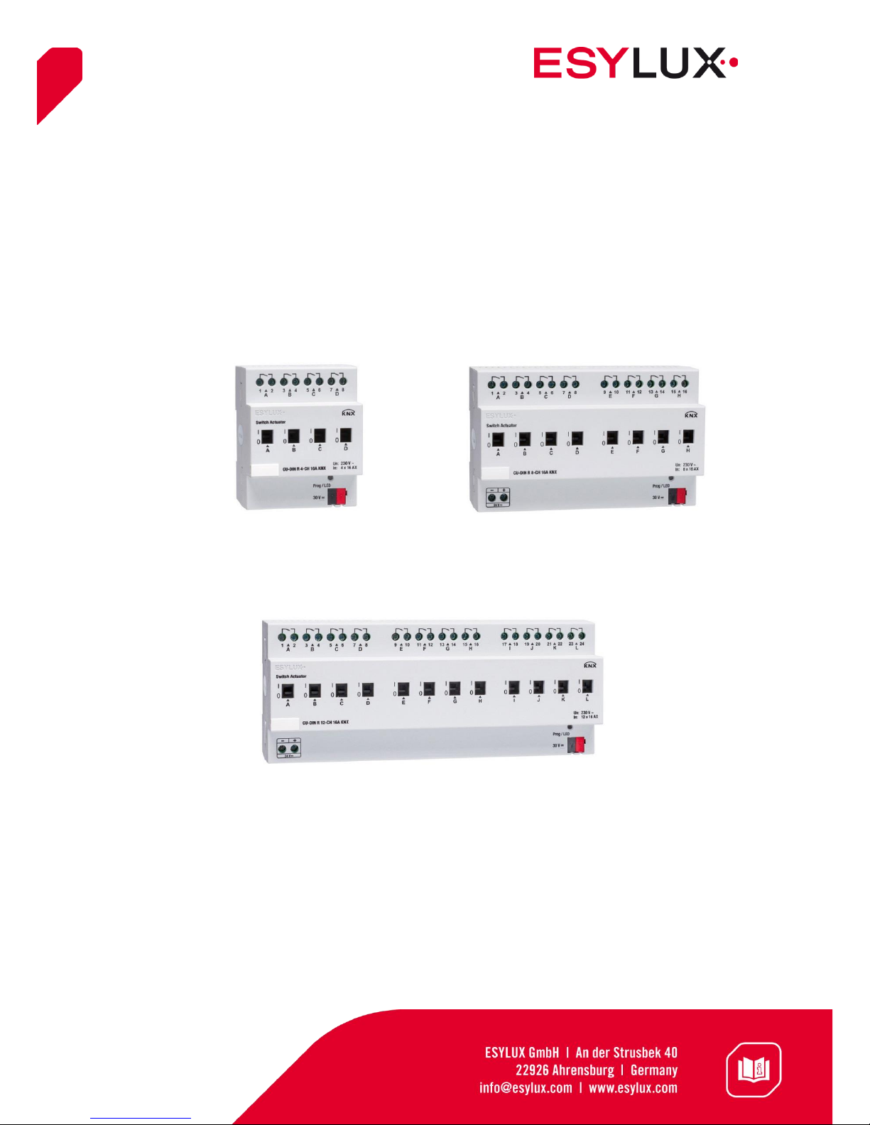
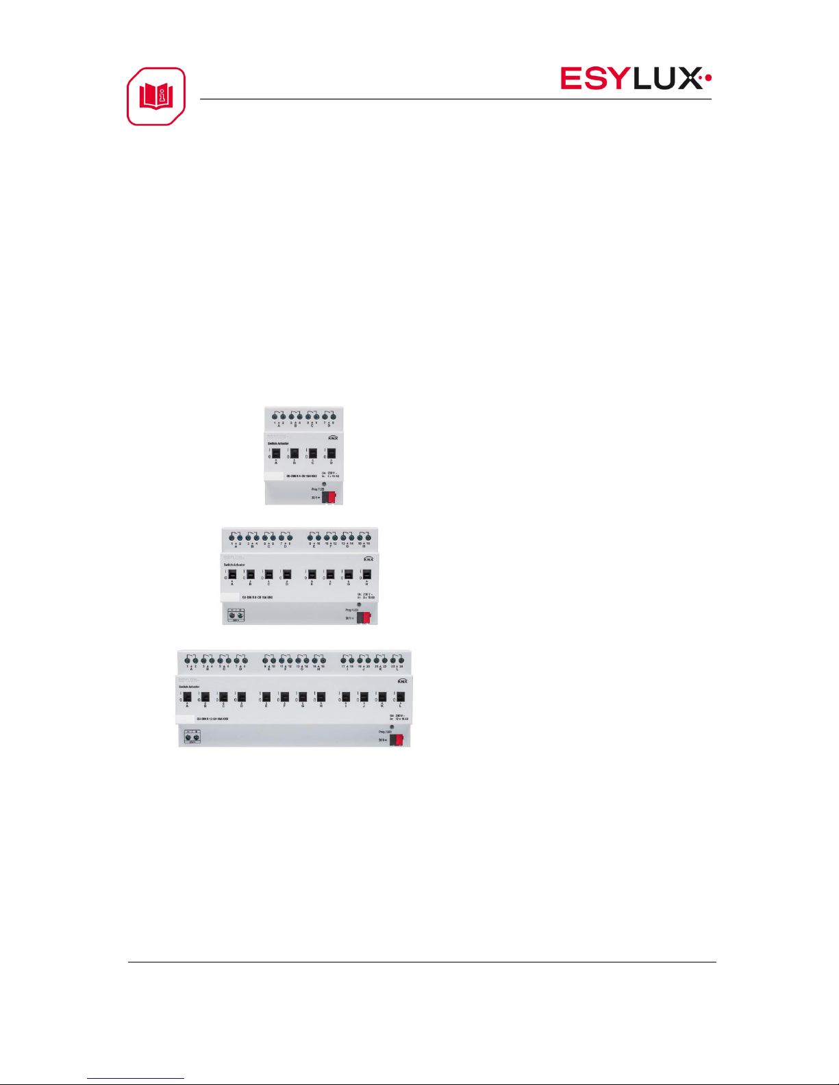
3 Product function
The switch actuators can be used for 4, 8 and 12 channels independent AC/DC
loads. The outputs for MAX 16 A can be switched ON or OFF on every output
channel and can be switched manually too. The CU-DIN R 4-CH does not
require an additional power supply. The CU-DIN R 8-CH and CU-DIN R 12-CH
require an additional 24 V DC power supply if all of the channels are frequently
operated at the same time, but normal operation is also possible if there is no
additional power supply. The following functions can be set individually for each
output channel:
Channel state response
Channel state after bus voltage
failure and recovery
Time function
Flashing
Staircase light
Delay
Scene
Scene number: 1-64
Threshold
Two threshold values
Curtain
Top/left<->bottom/right
Logic
AND/OR/XOR/GATE
Heating control
PWM
CU-DIN R 4-CH 16 A KNX
CU-DIN R 8-CH 16 A KNX 6 / 54
CU-DIN R 12-CH 16 A KNX
USER MANUAL
4 Hardware
The technical properties of the ESYLUX KNX/EIB switch actuators are described
in the following sections.
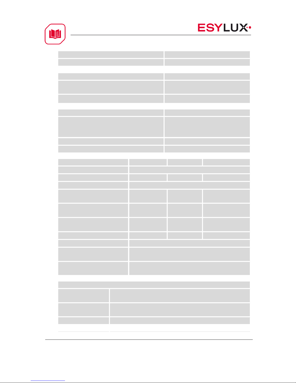
4.1 Technical data
Power supply
Operating voltage (supplied by
the bus)
21–30 V
Current consumption EIB/KNX
(operation)
< 15 mA
Current consumption EIB/KNX
(standby)
< 5 mA
Power consumption EIB/KNX
(operation)
< 450 mW
Power consumption EIB/KNX
(standby)
< 150 mW
Output nominal values
Type of
device M/R
R 4-CH
R 8-CH
R 12-CH
Number of
contacts
4 8 12
Rated
current
16A
16A
16A
Power loss
per device at
max. load
2.7 W
5.4 W
8 W
Rated
voltage
230V ~
230V ~
230V ~
Output switching currents
AC operation (cos1 = 0.8)
Fluorescent lighting load
Minimum switching capability
12 A / 230 V
16 A / 230V (300 μF)
0.1 mA / 1 V
CU-DIN R 4-CH 16 A KNX
CU-DIN R 8-CH 16 A KNX 7 / 54
CU-DIN R 12-CH 16 A KNX
USER MANUAL
DC current switching capability (ohmic
load) output life expectancy
Mechanical life
Electrical life (230 V/cos phi =
0.8)
16 A / 12 V DC
> 1,000,000
> 100,000
Output switching delay without additional
DC power
Max. delay time of relay per
position change (charge time of
the capacity)
R 4-CH R 8-CH R 12CH
400 ms 400 ms 400
ms
Note: Note: The device has a voltage (capacity of relay driver) detect function.
It remains active and stores the state of the relays in the memory of the device
when the voltage goes down to stop level. This function is thereby able to
successfully prevent the relay from becoming inactive. When the voltage
(capacity of relay driver) goes back up to active level, the state of the relays are
recovered from the memory, thereby enabling the relays to become active again.
This function is very useful when there is no additional DC power application in
the system, and the delay time is approx. 0.4 s on switch state change when the
charge of the capacity is not enough.
Output switching delay with additional DC
power
Max. delay time of relay per position
change (charge time of the capacity)
R 8-CH R 12-CH
100 ms 100 ms
Note: in some applications, the relay needs to be switched ON/OFF frequently,
and does not allow too much delay time. In such cases it can be connected to
an additional 24 V power supply. The max. current required are 24 mA when
the relay is actived, and required the standby current is 4 mA. The delay time is
approx. 400 ms on switch state change when the applied power is not sufficient.
Connections
EIB/KNX
Bus Connection Terminal
0.8 mm Ø, single core
Load circuits
Screw terminal with slotted head
0.2–4 mm² multi-core
0.4–6 mm² single-core
CU-DIN R 4-CH 16 A KNX
CU-DIN R 8-CH 16 A KNX 8 / 54
CU-DIN R 12-CH 16 A KNX
USER MANUAL
Cable shoe
12 mm
Tightening torque
Max. 0.8 Nm
Operation and display
Red LED and EIB/KNX push
button all in one
For assignment of the physical
address
Contact position indication
Relay lever
Temperature range
Operation
Storage
Transport
0°C – +45°C
-40°C – +55°C
-25°C – +70°C
Environmental conditions
Humidity
Max. 93%, non-condensing
Appearance design
Modular
DIN-Rail modular installation
Type (M/R)
R 4-CH
R 8-CH
R 12-CH
Dimensions
90 x W x 65
Width W (unit
mm)
72
144
216
Mounting width
(1SU=18 mm)
4SU
8SU
12SU
Mounting depth
(unit mm)
65
65
65
Weight (unit kg)
0.26
0.49
0.72
Installation
Use 35 mm mounting rail
Mounting
position
Electric switch box
Material and
colour
Plastic, white
CE Mark in accordance with
EMC
Standard
2004/1008/EC
LVD
Standard
2006/95/EC
RoHS
2011/65/EU
CU-DIN R 4-CH 16 A KNX
CU-DIN R 8-CH 16 A KNX 9 / 54
CU-DIN R 12-CH 16 A KNX
USER MANUAL
Note: All loads, at 230 V AC
Motors
3 KW
Lamps
Incandescent lamp load
3500 W
Low-volt halogen lamps
Inductive transformer
Electronic transformer
Halogen lamp 230V
1800 W
2000 W
3500 W
Mercury-vapour lamp
Uncompensated luminaire
Parallel compensated
2800 W
2800 W
Fluorescent lamp T5/T8
Uncompensated luminaire
Parallel compensated
DUO lamp
3500 W
2000 W
2000 W
Dulux lamp
Uncompensated luminaire
Parallel compensated
1500 W
1500 W
Switching performance (contact)
Max. peak inrush current IP (120 μs)
Max. peak inrush current IP (240 μs)
Max. peak inrush current IP (480 μs)
Max. peak inrush current IP (1000 μs)
600 A
480 A
300 A
170 A
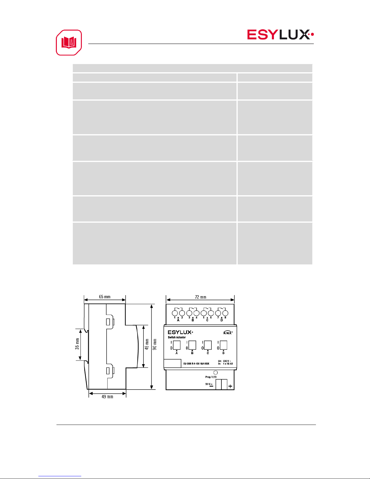
4.2 Dimension drawings
4-CH
8-CH
12-CH
72 mm
144 mm
216 mm
CU-DIN R 4-CH 16 A KNX
CU-DIN R 8-CH 16 A KNX 10 / 54
CU-DIN R 12-CH 16 A KNX
USER MANUAL
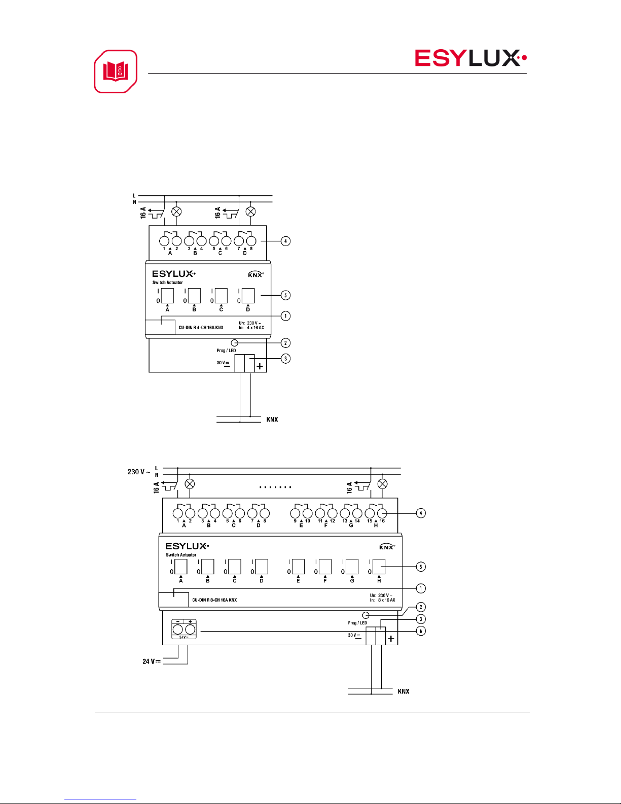
4.3 Wiring diagram
Note: On the input side, the device is to be protected against short circuits with
a 16 A circuit breaker.
1. Label area
2. Programming button&programming
LED
3. KNX/EIB bus connector
4. Terminal for load connection
5. Contact position indication and
manual operation
6 Additional power 24 V (max. 24 mA in
operation, min. 4 mA in standby).
CU-DIN R 4-CH 16A KNX
CU-DIN R 8-CH 16A KNX
CU-DIN R 4-CH 16 A KNX
CU-DIN R 8-CH 16 A KNX 11 / 54
CU-DIN R 12-CH 16 A KNX
USER MANUAL
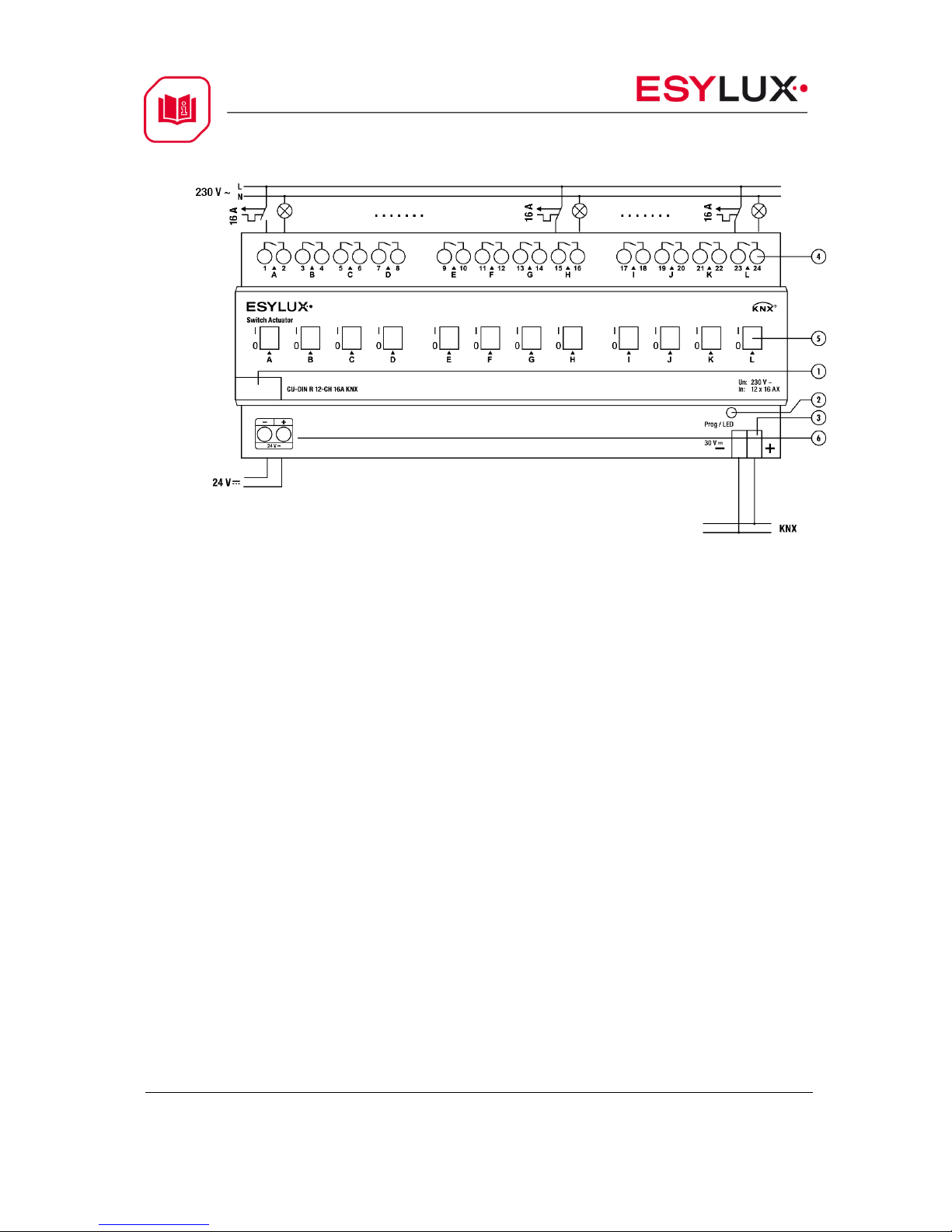
CU-DIN R 12-CH 16A KNX
Note: a) Dimensions of the space to be provided for each switch
b) Dimensions and position of the means for supporting and fixing the switch
within this space
c) Minimum clearance between the various parts of the switch and the
surrounding parts where fitted
d) Minimum dimensions of ventilation opening, if needed, and their correct
arrangement.
e) Protective devices (e.g. fuses, automatic protective devices, etc.) to be
connected to the load to avoid overloading
4.4 Maintenance and cautions
Please read this user manual carefully before operation.
Do not operate close to interfering devices.
The site should be ventilated with good cooling environment.
Take care to damp-proof, quake-proof and dust-proof.
Avoid rain, other liquids or caustic gas.
Please contact professional maintenance staff or ESYLUX service centre for
repair or fix.
Remove the dust regularly and do not wipe the unit with volatile liquids like
alcohol, gasoline, etc.
If damaged by damp or liquid, turn off immediately.

CU-DIN R 4-CH 16 A KNX
CU-DIN R 8-CH 16 A KNX 12 / 54
CU-DIN R 12-CH 16 A KNX
USER MANUAL
Regularly check the wiring and other related circuits and cables, and
replace faulty circuitry when necessary.
For security, each wiring should be connected to an MCB or fuse
Installation location should be well-ventilated; pay attention to moisture,
shock and dust.
5 Software
The ESYLUX KNX/EIB switch actuator database can be used with ETS3.0F, ETS4
and ETS5 for the programmation. The device types are CU-DIN R 4-CH, CU-DIN
R 8-CH and CU-DIN R 12-CH and the database names are:
EC10430282_ CU-DIN R 4-CH 16 A KNX.VD5
EC10430299_ CU-DIN R 8-CH 16 A KNX.VD5
EC10430305_ CU-DIN R 12-CH 16 A KNX.VD5
All parameters and interfaces are described in the following paragraph.
Each channel output of the switch actuators is independent and equal. So,
understanding of only one channel output is sufficient. The following paragraph
will describe the first channel output in detail.
CU-DIN R 4-CH 16 A KNX
CU-DIN R 8-CH 16 A KNX 13 / 54
CU-DIN R 12-CH 16 A KNX
USER MANUAL
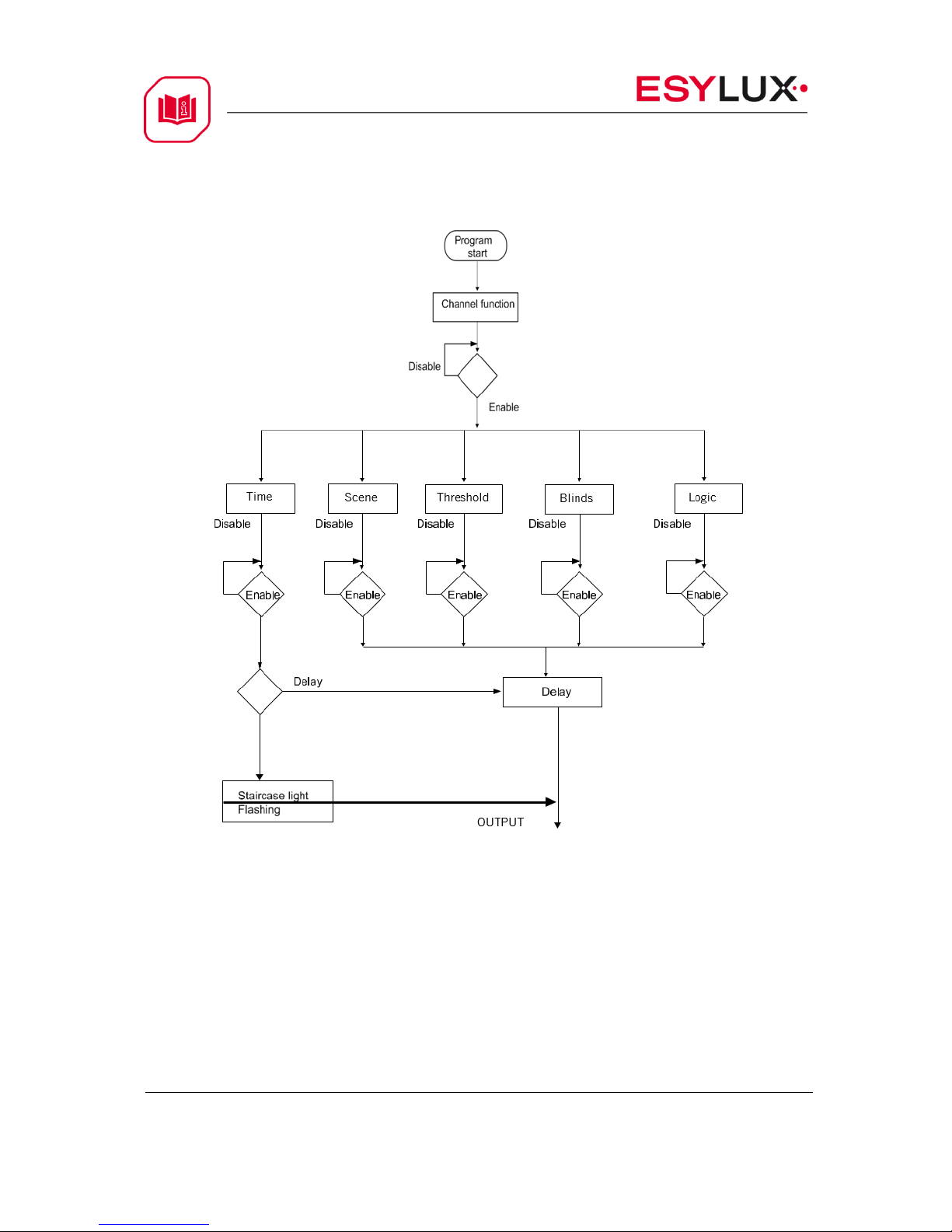
5.1 Program functions diagram
CU-DIN R 4-CH 16 A KNX
CU-DIN R 8-CH 16 A KNX 14 / 54
CU-DIN R 12-CH 16 A KNX
USER MANUAL
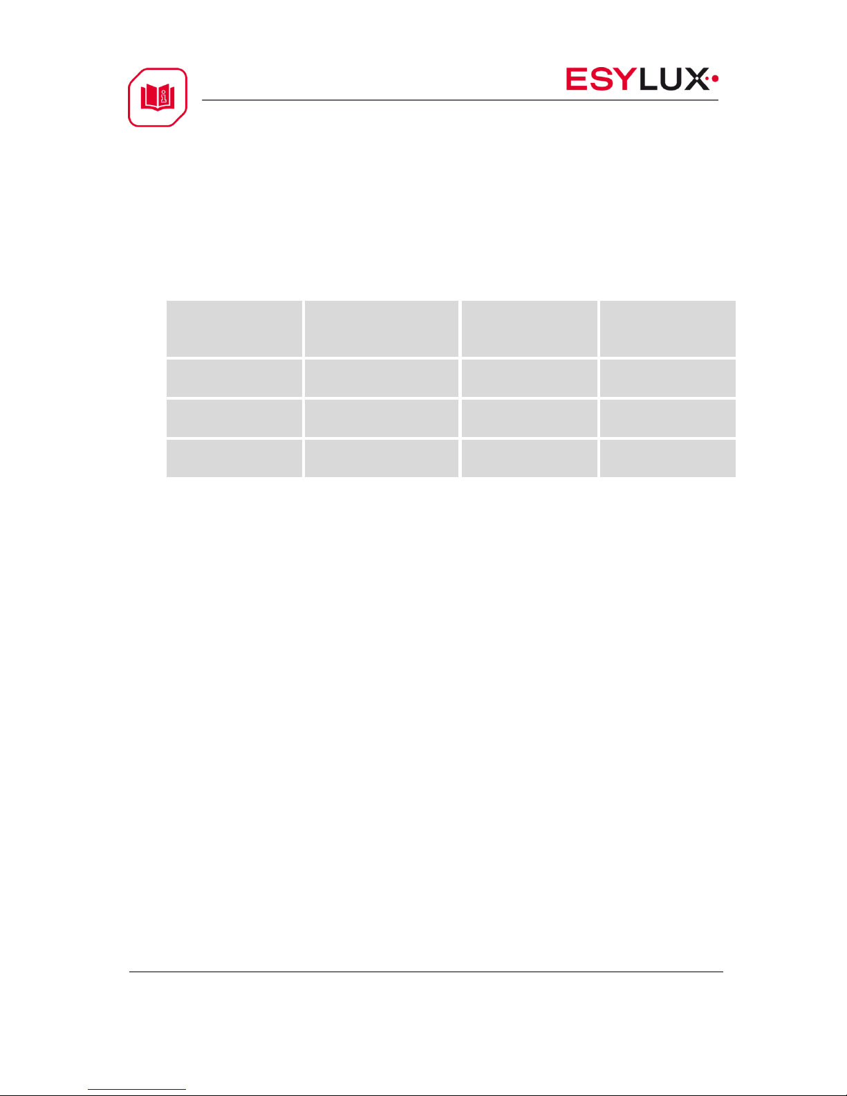
5.2 Defining object/association/group address
The following table shows the max. number of communication objects,
associations and group addresses. The object is assigned to certain functions of
the channel output pages. If the functions are activated, the corresponding
objects will be available. One or more group addresses can be assigned to an
object. The association will connect group addresses to the object.
Type
VD5
Max. number of
communication
objects
Max. number of
associations
Max. number of
group addresses
CU-DIN R 4-CH
16 A
90
254
254
CU-DIN R 8-CH
16 A
170
254
254
CU-DIN R 12-CH
16 A
250
254
254
Table 1: Overview of the max. number of objects, max. number of associations
and max. number of group addresses.
Note: ETS3.0F-> Import “VD3” to “VD5”.
ETS4-> Import “.KNXPROD”.
ETS5
CU-DIN R 4-CH 16 A KNX
CU-DIN R 8-CH 16 A KNX 15 / 54
CU-DIN R 12-CH 16 A KNX
USER MANUAL
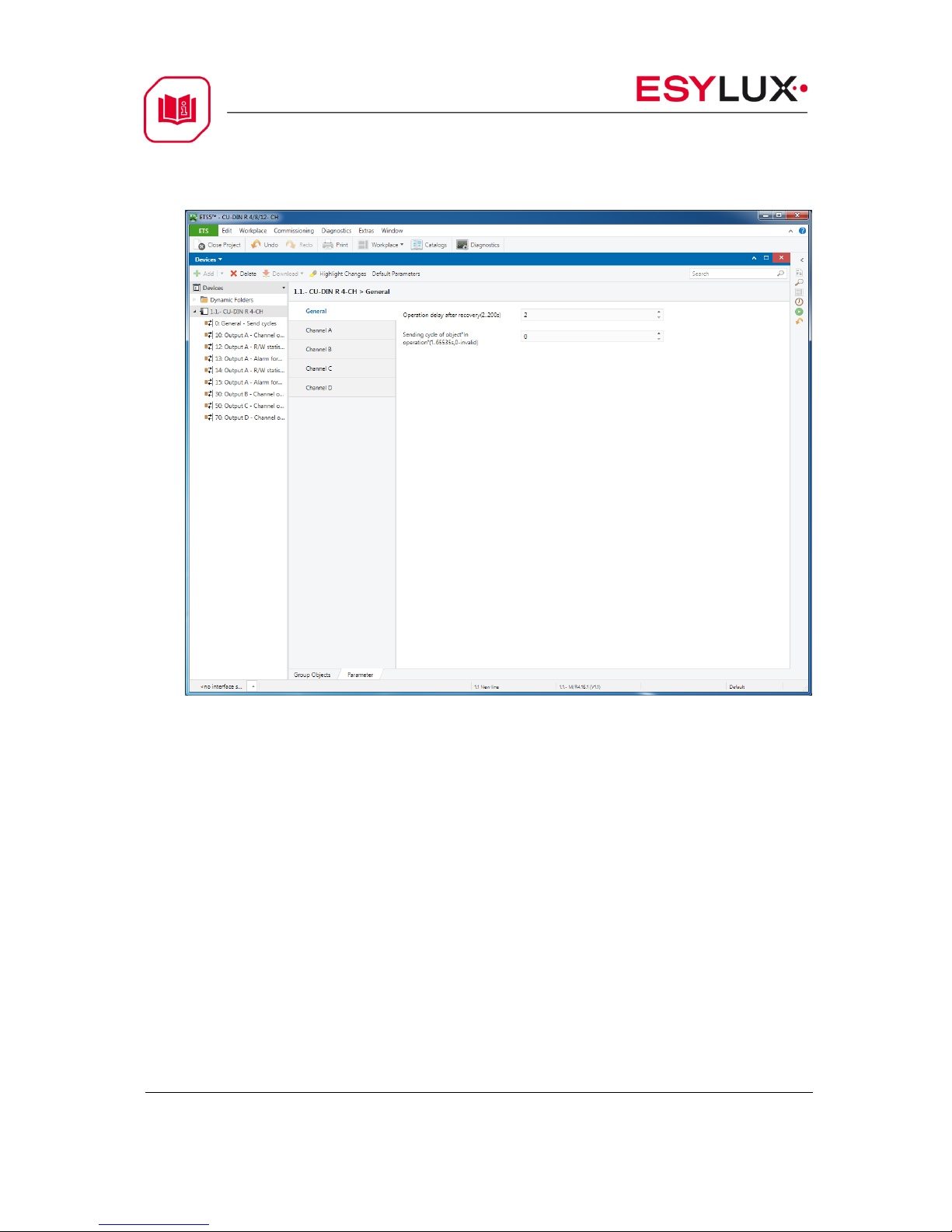
5.3 Function parameter “General”
Fig 1: “General” parameters window
In the General parameters window, two parameters can be set:“Switching delay
after recovery ” and “Cycle send general telegram”.
Operation delay after recovery (2–200 s)
Can be used for a delay time of 2–200 s after the power is available again. The
default value is 2 seconds. The min. value is 2 seconds and the max. value is
200 seconds.
Options: 2-200 s
After voltage recovery and the adjusted delay-time (2–200 s) is counted down
the switch is ready for use. This function is selected by the user.
Sending cycle of object “In operation”(1–65,535 s, 0 - invalid)
The range of the parameter is 0 to 65,535 s. A zero parameter disables the
function, other parameters enable this function
Options: 1–65,535 s
CU-DIN R 4-CH 16 A KNX
CU-DIN R 8-CH 16 A KNX 16 / 54
CU-DIN R 12-CH 16 A KNX
USER MANUAL
When the parameter is set to non-zero, the device will send telegram data
cyclically on timeout. Send the value alternately between 0 and 1.
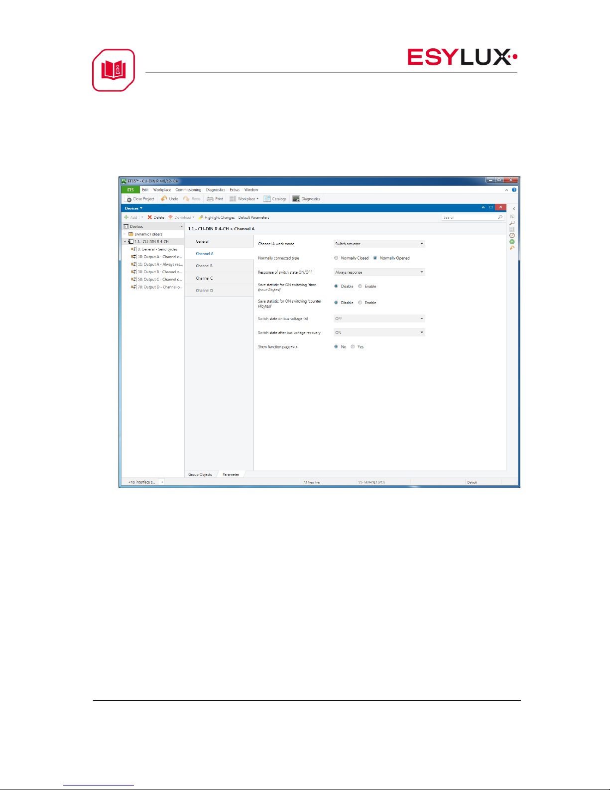
5.4 Function parameter “Channel A”
Fig 2: “Channel A” window
In the “Channel A” parameter window, some common functions can be set up.
After selecting a function and downloading the database to the device, the
device will work in accordance with the selected function.
Note: take channel A as an example; other channels are the same as A.
Channel A work mode:
The functions of Channel A work mode output can be selected with three
parameters.
Options: Switch actuator
Heating actuator
Inactivated
If “Inactivated” is selected, channel A function will be invalid, but it will work in
the other two modes.
CU-DIN R 4-CH 16 A KNX
CU-DIN R 8-CH 16 A KNX 17 / 54
CU-DIN R 12-CH 16 A KNX
USER MANUAL
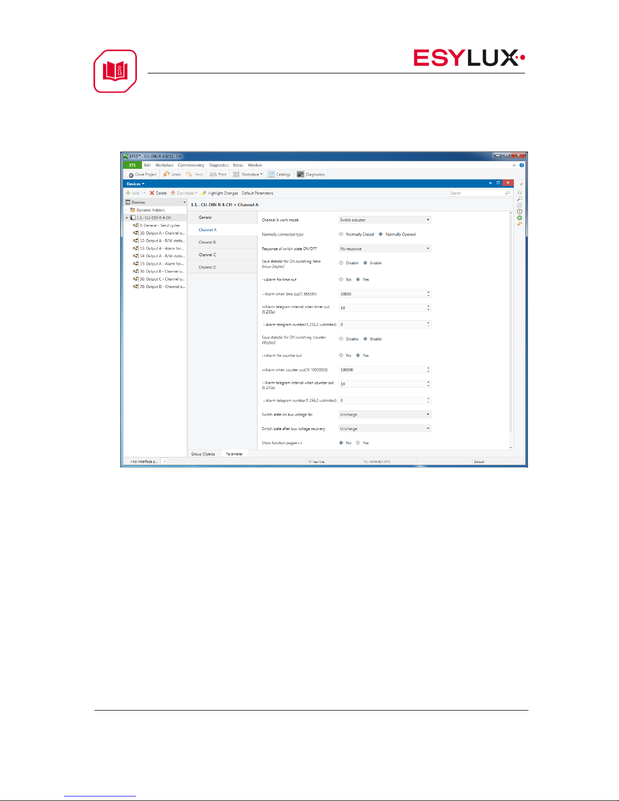
5.5 Channel mode “Switch actuator”
Fig 3: Switch actuator window.
More functions can be set up in this mode; the following section provides a
detailed description of the Switch Actuator mode.
Normally connected type
This parameter is the choice of the type of access load
Options: Normally closed
Normally opened
Normally closed: Contact in de-energised state is closed.
Normally Opened: Contact in de-energised state is open.
Response of switch state ON/OFF
This parameter provides a choice of the switching state feedback.
Options: No response
Always respond
Only after change
No response: No response of the switch state.
 Loading...