

ESX VISION2 Series, VE1800.2, VE1000.2, VE800.4, VE1200.4 Owner's Manual


OWNER'S MANUAL
PageContent
SPECIFICATIONS
INSTALLATION
Installation of the Amplifier, Electrical Connection
2-CHANNEL AMPLIFIER VE 900.2 & 1500.2
Functions & Controls
2-Channel-Mode: 2 Speakers / Stereo
1-Channel-Mode: 1 Subwoofer / Mono bridged
4-CHANNEL AMPLIFIER VE 600.4 & 1000.4
Functions & Controls
4-Channel-Mode: 2 Frontspeakers / Stereo & 2 Rearspeakers / Stereo
3-Channel-Mode: 2 Frontspeakers / Stereo & 1 Subwoofer / Mono bridged
2-Channel-Mode: 2 Subwoofer / Mono bridged
19
20
21
24
25
26
29
30
31
SPECIAL FEATURES
TROUBLE SHOOTING
32
33
18

SPECIFICATIONS
Channels
Watt RMS @ 4 Ohm
Watt RMS @ 2 Ohm
Watt RMS @ 1 Ohm
Watt RMS @ 4/2 Ohm mono bridged
Watt MAX. @ 4 Ohm
Watt MAX. @ 2 Ohm
Watt MAX. @ 1 Ohm
Watt MAX. @ 4/2 Ohm mono bridged
Efficiancy Factor @ 4 Ohm
Maxi-Fuse*
Damping Factor
Signal to Noise Ratio
Channel Separation
Harmonic Distortion (THD&N)
Input Impedance
Operation Voltage
CH1 & CH2
Variable Highpass 12dB/24dB
Variable Lowpass 12dB/24dB
Bass-Boost @ 45Hz
Phase Shift
Input Sensitivity
VE1000.2
2
2 x 175
2 x 300
2 x 500
1 x 600 / 1000
2 x 350
2 x 650
2 x 1000
1 x 1200 / 2000
64 % 68% 64%
70 A 2 x 70 A 70 A
> 400
> 100 dB
> 90 dB
< 0,05 %
> 40 kOhm > 40 kOhm > 40 kOhm > 40 kOhm
12 - 16 V
10Hz - 2500Hz
40Hz - 4000Hz
0 - 18 dB
0 - 180
0,15 - 9 V
VE1800.2
2
2 x 400
2 x 700
2 x 900
1 x 1400 / 1800
2 x 800
2 x 1400
2 x 1800
1 x 2800 / 3600
> 400
> 100 dB
> 90 dB
< 0,05 %
12 - 16 V
10Hz - 2500Hz
40Hz - 4000Hz
0 - 18 dB
0 - 180
0,15 - 9 V
VE800.4
4
4 x 80
4 x 140
4 x 200
2 x 280 / 400
4 x 160
4 x 280
4 x 400
2 x 560 / 800
> 400
> 100 dB
> 90 dB
< 0,05 %
12 - 16 V
10Hz - 1000Hz
–
–
0 - 180
0,15 - 9 V
VE1200.4
4
4 x 125
4 x 225
4 x 300
2 x 450 / 600
4 x 250
4 x 450
4 x 600
2 x 900 / 1200
65%
2 x 60 A
> 400
> 100 dB
> 90 dB
< 0,05 %
12 - 16 V
10Hz - 1000Hz
–
–
0 - 180
0,15 - 9 V
CH3 & CH4
Variable Highpass 12dB/24dB
Variable Lowpass 12dB/24dB
Bass-Boost @ 45Hz
Input Sensitivity
Dimensions in mm
Width x Heigth
Lenght Heatsink
All specifications are subject to change without notice
257 x 60
455 535
257 x 60
10Hz - 2500Hz
40Hz - 4000Hz
0 - 18 dB
0,15 - 9 V 0,15 - 9 V
257 x 60
445 505
10Hz - 2500Hz
40Hz - 4000Hz
0 - 18 dB
257 x 60
* suitable for 4 / 2 ohm operation (1 Ohm Mode only for music playback)
19
INSTALLATION
VE1000.2 / VE1800.2 / VE800.4 / VE1200.4
General Installation Notes
The amplifier is generally mounted in the rear trunk area but can be mounted in any convenient area such as beneath a seat. Please be sure to
locate this unit where you have reasonable air circulation and protection from moisture. When considering the mounting location you should
minimize the length of the power and speaker leads. Minimizing both leads will yield a more reliable installation. It is also important to ensure that
the heat sink fins are not against a panel or a surface, preventing air circulation. Do not install the amplifier on a subwoofer box or on vibrating
parts of the vehicle, since the vibrations can cause damages to the amplifier´s electrical components.
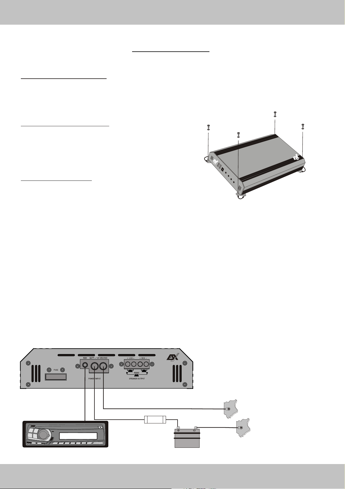
Installation of the amplifier
Mark the location for the mounting screw holes by using the amplifier as a
template. Drill holes at the marked locations and firmly fasten the amplifier
in place with the mounting screws supplied in the accessory kit. Before drilling
or cutting any holes, investigate the layout of your automobile thoroughly:
Take care when working near the gas lines, the hydraulic lines or
the electrical wiring at your car.
Electrical Connection
Ground (GND)
This wire is the electrical ground and must be fastened securely to the vehicle chassis.
The best method is to use a threading sheet metal screw since the threads cut into bare metal. Ensure that all paint or other insulation is removed
around the hole area, and using self tapping screw, securely affix the bare wire ends to the vehicle chassis. Use a piece of cable which is as short
as possible - use the same gauge as used for the +12V cable. Make sure that the connection is safe, a loose connection may result in amplifier
noise and fault condition.
Remote (REM)
Many music sources have an output terminal for connection of the remote turn-on of the power amplifier. If a radio doesn't have a remote
turn-on feature, then you can use the antenna relay wire, which activates the antenna motor. Please note, if the power antenna retracts
when the radio is operating, then you cannot use the antenna relay wire to operate the remote turn-on.
Battery Connection (+12V)
This wire is usually connected directly to the positive battery terminal. Ensure that the + power supply wire is fused via an assigned fuse in
line with the + power supply wire. Please use a sufficient gauge for the installed amplifiers (min 16-25 mm). This connection must be
completed using spade plug with insulating sleeve. The ESX VE Vison amplifiers are optimized for a operating voltage of 12-16 Volts.
Maxi-Fuse (FUSE)
The mounted Maxi-Fuses protects the amplifier of short circuit and overload. If you have to replace the Fuses, only replace with a equivalent
valued Fuse. The original installed Fuse is optimized for a 4 / 2 Ohm operation and 1 Ohm operation only for musical playback. In the 1 Ohm
operation under constant load the current consumption is increased, this means you have to replace the original Fuse by a appropriate Fuse with
a higher Value (Ask your retailer).
Remote turn-on
FUSE
Fuse
Ground
Ground
Battery
20
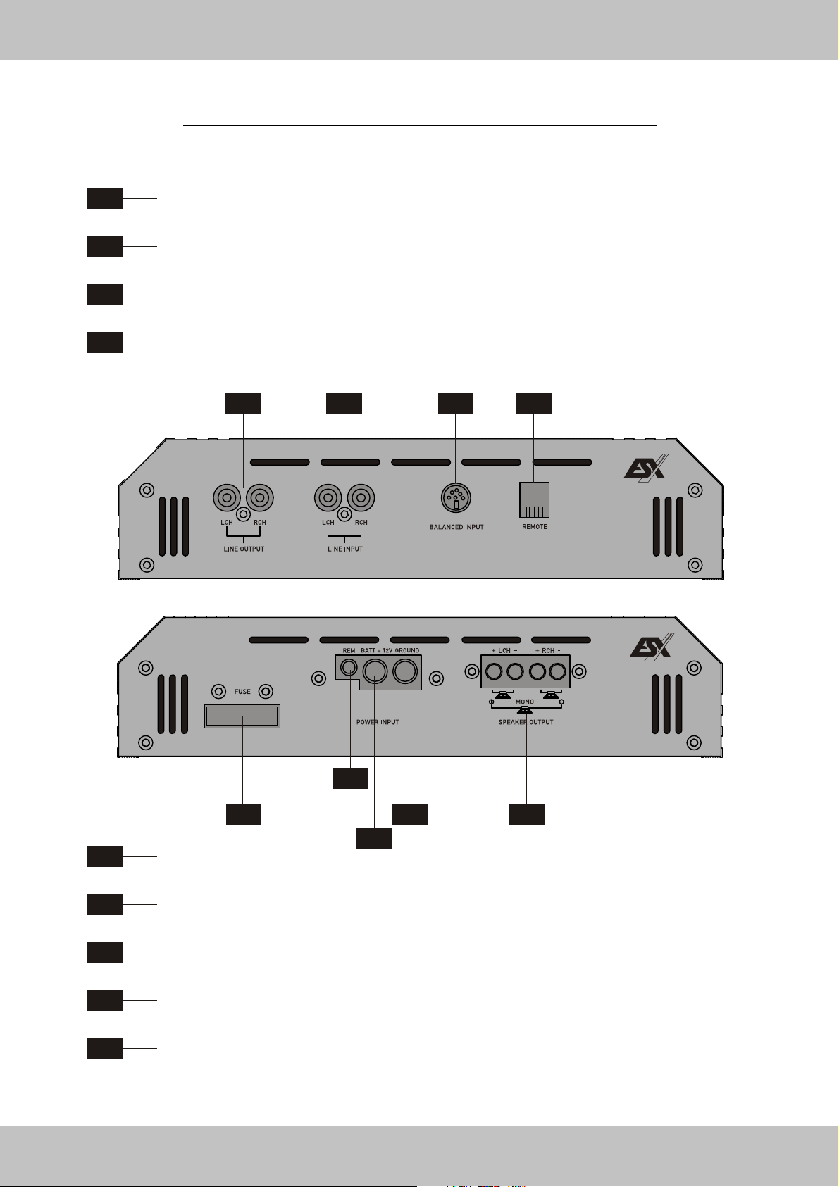
FUNCTIONS & CONTROLS TOP-PANEL
2-Channel Amplifier VE1000.2 / VE1800.2
F1
F2
F3
F4
LINE OUTPUT
Provides a full range line level (RCA) output that allows you to trigger additional amplifiers.
LINE INPUT
This allows you to connect the head unit outputs (CH 1/2 or CH 3/4) by appropriate RCA cables.
BALANCED INPUT
Accepts a balanced symmetrical line signal from a appropriate Signal Transmitter. (See page 32)
REMOTE
Terminal for the included REMOTE CONTROL to adjust the Bass Level.
F1
F2 F3 F4
R1
R2
R3
R4
R5
R3
R1 R4 R5
R2
FUSE
Fuse block to prevent damages of the amplifier (See page 20).
BATT +12V
Terminal for the plus connection (See page 20).
REM
Terminal for remote turn-on of the head unit (See page 20).
GROUND
Terminal for the ground/minus connection (See page 20).
SPEAKER OUTPUT
Terminal for the left and right speaker or bridged subwoofer (MONO mode).
Attend the several examples for Loundspeaker Wiring on the following pages!
21
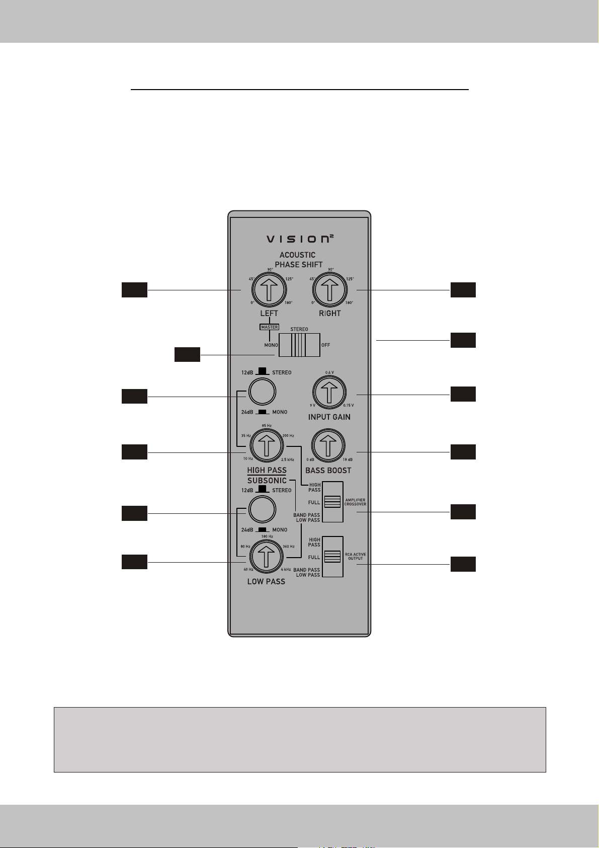
FUNCTIONS & CONTROLS TOP-PANEL
2-Channel Amplifier VE1000.2 / VE1800.2
T1
T5
T7
T9
T11
T2
T4
T3
T6
T8
T10
T12
NOTE: If the amplifier's top-panel is white illuminated, the amplifier is in power mode. If the display is red illuminated,
the protection mode of the amplifier is activated caused by a malfunction (See page 33)
CAUSES: Overheating, short circuit on the speakers, overload (caused by low-impedance or low-power) or damage .
22
 Loading...