

Page 1
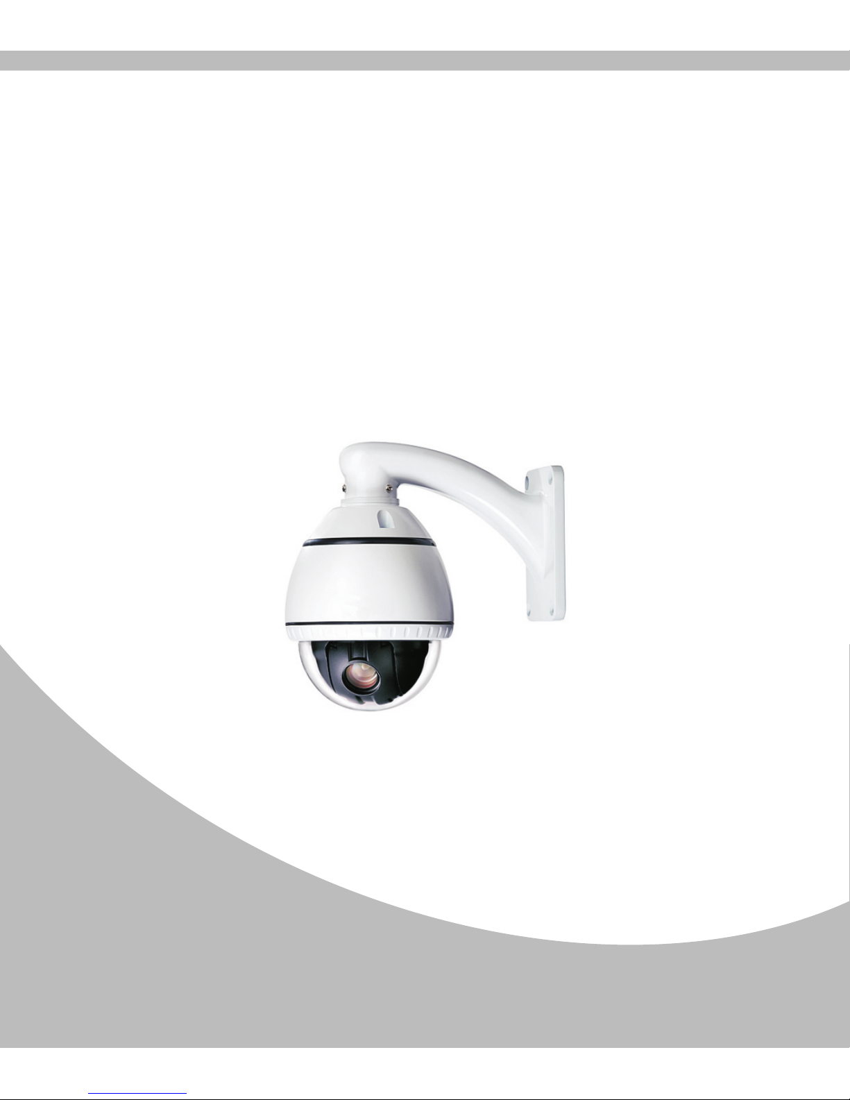
Mini High Speed Dome Camera
User Manual
Page 2

Page 3

Contents
1. Introduction
Features………………………………………………………………………
2
Specifications………………………………………………………………...
4
2. Installation
Installation and connection…………………………………………………...
5
DIP Switch Setup……………………………………………........................ 6
3. Operation
Check points when power up…………………………………………………
8
Control……………………………………………………………...................
10
Camera and Lens control……………………………………………………..
10
4. How to use OSD Menu
Basic operation of main menu……………………………………………….. 11
Main Menu Introduction……………………………………………………...
11
System Information…………………………………………………………...
12
ADDR setting………………………………………………………………… 13
Motion…………………………………………………………………………
13
Patterns……………………………………………………………………….. 16
Camera……………………………………………………………………….. 17
Cruise Setting………………………………………………………………… 28
Display Setup…………………………………………………………………
29
Restore Factory Default……………………………………………………… 29
Reboot System……………………………………………………………….. 30
Exit……………………………………………………………………………
30
5.Trouble Shooting
Trouble shooting………………………………………………………………
30
6.Safety Information
Safety information……………………………………………………………. 31
.....
....
.
...
.
.
..
.
...
....
...
....
...
...
.
..
.....
..
...
1
Page 4

1. Introduction
1.1 Features
※ Camera Specifications:
CCD Sensor: 1/4″ Interline Transfer CCD.
Zoom Magnification: 10X Optical zoom, 10X Digital zoom.
Day & Night function : The camera is configured to switch to the black and white
mode automatic al ly under low l ig ht condit io ns and at nigh t with mechanica l IR
Cut filter for clear images.
Various focus mode: Auto Focus / Manual Focus / Semi-Auto Focus.
※ Powerful Pan / Tilt Functions
Max. 360°/sec high speed Pan / Tilt motion.
Automatic turn over.
Support bearing indication.
Programmable cruise and presets.
Soft address enables to set up the address and number of the camera.
Adopt Vector Drive Technology, Pan / Tilt motions are accomplished in a shortest
path . As a resu lt , ti me to t ar ge t view is redu ce d serious ly and the vid eo on t he
monitor is very nature to watch.
Fo r j og ope rati on usi ng a con trol ler , si nce ul tra sl ow spe ed 0.0 5°/s ec can b e
reached. It is very easy to locate camera to desired target view.
Support zoom proporti on al Pan / Tilt speed. Camera can be move d to a desired
position in accurate manner even through high zoom ratio.
※ Preset, Linear, Preset position cruise, Pattern, Auto Scan.
Max. 256 presets are assignable and characteristics of each preset can be set up
independently.
Linear scan enables to move camera repetitive between two preset positions with
assigned speed.
Preset position cruise: the group can have max 30 entities of preset. This enables
for camera to move a combinations of this functions repetitively.
2
Page 5

4 Pa t te rn s with 100 com ma nd s can b e recorde d and e xe cu te d. This e n ab les the
camera to track a surveillance trajectory as closely as possible.
360° continuous scan.
360° intermittent scan. The camera will have seconds stop during each 90°turning.
Auto scan : this enables to move the camera to execute the certain scan when no-
operation for a long time.
Reserved Presets for special purpose : besides regular 256 presets, direct calling
of reserved presets enable to set up many of camera functions with / without using
OSD menu.
※ PTZ( Pan /Tilt /Zoom) Control
RS485 Communication.
Pelco D / Pelco P, special protocols available.
※ OSD (On screen Display) Menu
OSD menu is provided to display the status of camera and to configure the functions
interactively.
2 Language are supported.
Each display item can be turned ON or OFF independently.
3
Page 6
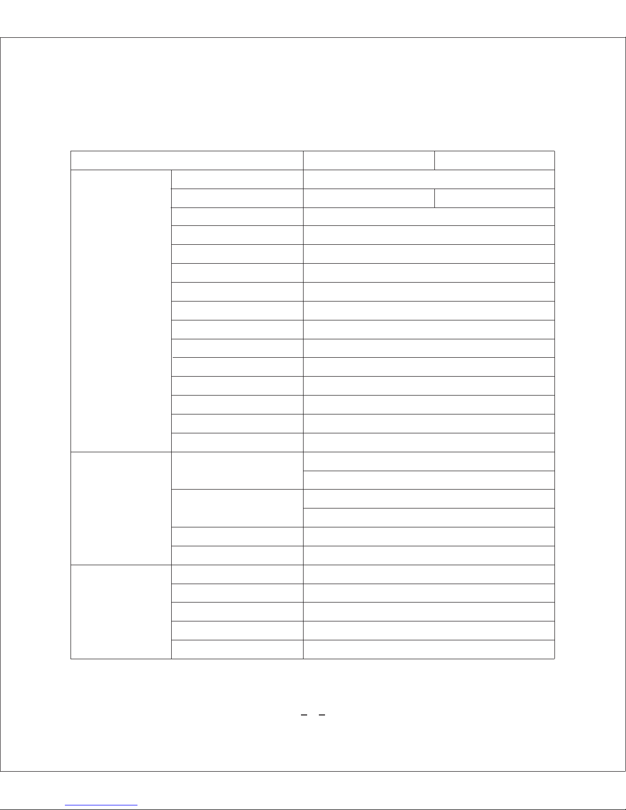
1.2 Specifications
4
CCD 1/4〞Interline Transfe r CCD
Max. Pixels 811(H) x 508(V ) 795( H) x 596(V)
Horizontal R esolution 500TV Line(Color), 570 TV Line(B/W)
S/N Ratio 50dB(AGC off)
Zoom X10 Optical Zoom, X10 Digit al Zoom
Focal Length F1.8, f=3.8~38m m
Min. illumin ation 0.7Lux(Color),0.02Lux (B/W), F1.8, 50 IRE
Day & Night Auto / Day/ Night functio n (ICR)
Focus Auto / Manual/ SemiAuto
Iris Aut o / Manual
Shutter Spee d 1/50~1/12000 0 sec
AGC Gen eral / High / Off
White Balanc e
BLC Low / Middle / High / Off
DNR Low / Middle / High / Off
Pan :0~360°(Endless) Tilt: 0~180°
Prese t : 360°/sec
Au to Pan : 1~180°/sec adjustabl e
Preset 256 Preset(Labe l, Camera Image Setting)
Cruise Auto Pan, Pattern, Scan.
Other Functi ons Aut o Flip, Auto Parking, Power up Action etc .
Communicat ion RS-485
Protocol Pelco-D, Pelc o-P, Special protocols avail able
Baud rate 2400, 4800, 9600
Language English
Video Signa l System NTSC PAL
ATW(Ind oo r/Out do or); AWC, Manua l (R ed, Blu e ga in adju st able)
Manual: P an 30 0°/se c; Til t 180°. (pro por tional to zo om)
Camera
General
Pan / Tilt
Range
Pan/Tilt Speed
Page 7
5
2. Installation
2.1 Installation and Connection
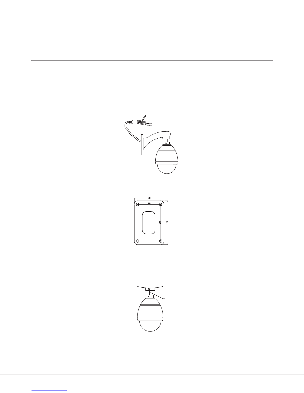
2.1.1. Wall Mount
(1) Connect Camera
Plug the ter mi na ls into the bo tt om of t he main unit, then, f ix the main un i t with
screws supplier.
(2) Bracket Installation
Use the screws provided to secure the wall mount to the wall.
2.1.2.Ceiling Mount
(1) Fix the main unit on the bracket.
After wiring cables to terminals , plug the terminals into the bottom of main unit .
Then, fix the main unit with screws provided
485 d ata cab le
power
BNC V ide o
The ca bl e cross t hr ough bo tt le posi ti on and
be out o f br each of b ot tle pos it ion
Page 8

54
1
28
5.
5
2.2 DIP Switch Setup
6
(2)Install ceiling mount bracket on the ceiling using screws provided.
2.1.3 Cabling
Connector Interface
Before you install the camera, you should set the DIP switches to configure the camera
ID, Baud rate, and communication protocol.
Default ID : 1
Baud rate: 2400
Protocol: Pelco-D.
485A Red
485B Blac k
DC 12V
BNC Video
Page 9
1 2 3 4 5 6 7 8
ON
OFF
0
1
2
3
4
5
6
7
8
1 2 3 4 5 6 7 8
0 0 0 0 0 0 0 0
1 0 0 0 0 0 0 0
0 1 0 0 0 0 0 0
1 1 0 0 0 0 0 0
0 0 1 0 0 0 0 0
1 0 1 0 0 0 0 0
0 1 1 0 0 0 0 0
1 1 1 0 0 0 0 0
0 0 0 1 0 0 0 0
1 2 3 4 5 6 7 8
0 1 0 1 0 0 0 0
0 0 1 0 1 0 0 0
0 1 1 1 1 0 0 0
0 1 0 0 1 1 0 0
0 0 1 0 0 1 1 0
1 0 1 0 0 1 1 0
0 1 1 0 1 0 0 1
0 0 0 1 0 0 1 1
1 1 1 1 1 1 1 1
1 0
2 0
3 0
5 0
1 0 0
1 0 1
1 5 0
2 0 0
2 5 5
1 2 3 4
ON
OFF
7
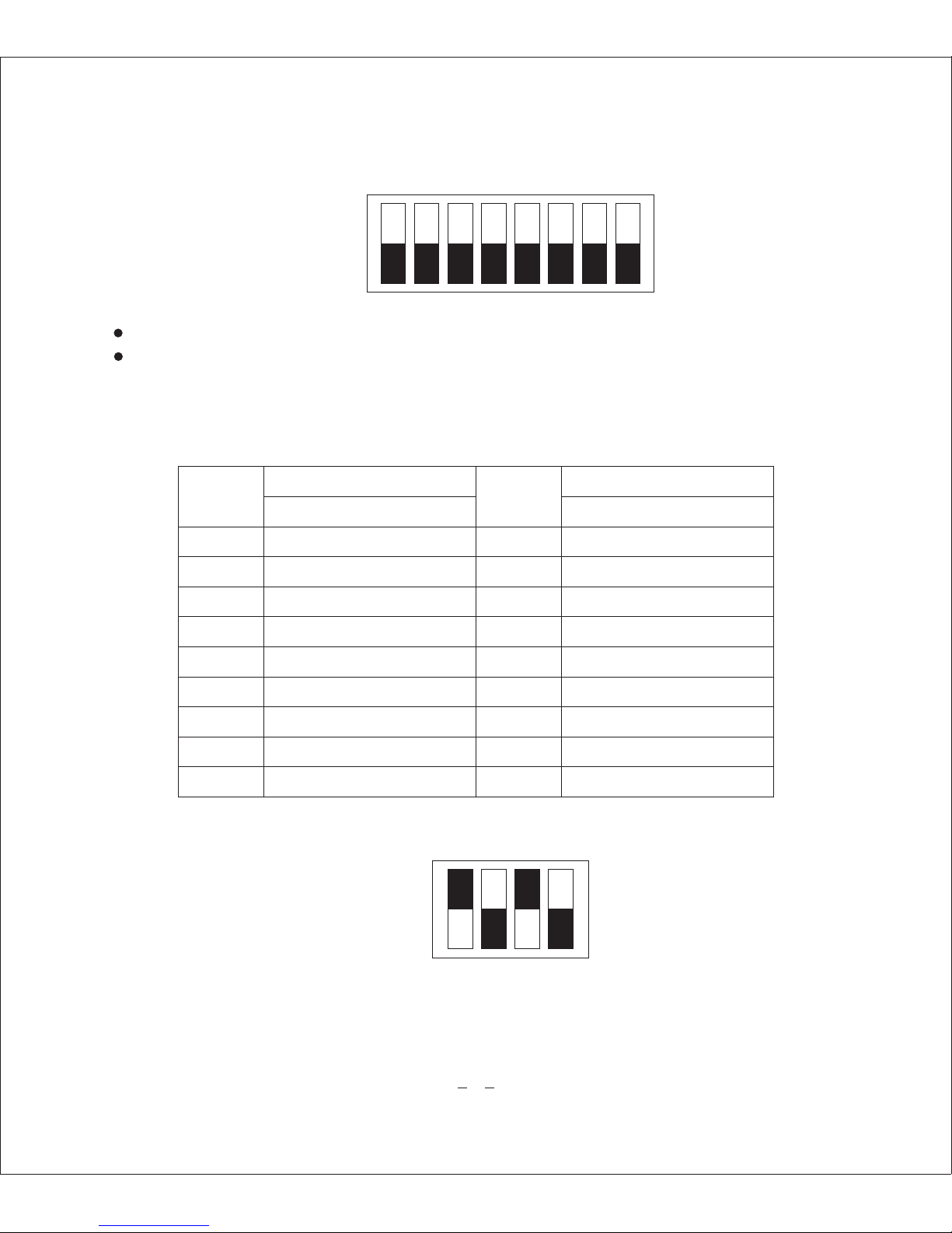
2.2.1 Camera ID Setup
The range of ID is 0~255. Factory default of Camera ID is 1.
ID number of camera is set using binary number. The number from 1~8 present 1, 2, 4,
8, 16, 32, 64, 128. For example, switch 1, 3, 5, 7 to “ON” position, the corresponding
ID should be 1+4+16+64=85.
The example is shown below.
ID No
ID No
Code Switch Code Switch
2.2.2 Communication Protocol and Baud rate Setup
Page 10
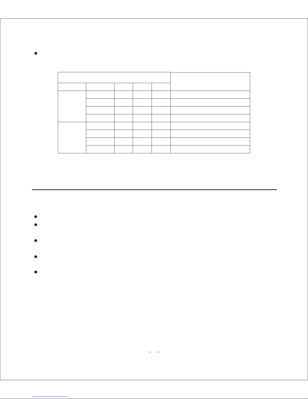
1 2 3 4
OFF OFF
ON OFF
OFF
ON
ON
ON
OFF OFF
ON OFF
OFF ON
ONON
PELCO-P
PELCO-D
9 6 0 0
2 4 0 0
4 8 0 0
9 6 0 0
8
3.Operation
Before power is connected, please check the cables carefully.
The camera ID of the controller must be identical to that of the camera to be controlled.
The camera ID can be checked in the System Information of OSD Menu.
If you controller supports multi-protocols, the protocol must be changed to match to
that of the camera.
If you change camera protocol by changing DIP switch , the change will be effective
after you reboot the camera.
Since the operation method can be different for each controller available , refer to the
manual for your controller if camera can not be controller properly.
3.1 Check points before operation
3.2 Operation
Note: The manual will refer to our CCTV tester to explain how to operate and control
the camera.
Pin No
Protocol
Protoc ol
Baud rat e
Auto
Reserved
Switch State
Select the appropriate protocol with DIP switch combination.
Page 11
9
3.2.1 Preset function pre-check
Check how to operate preset , Scan, Auto Pan and Pattern function with controller
or DVR in a d va nc e to o p er at e camera functio n using them.(re fe r to yo ur System
keyboard Manual)
If controller or DVR has no pattern button or function , use shortcut keys with preset
numbers. For more information, refer to “Reserved Preset” in this manual.
Use “UP, DOWN, LEFT, RIGHT” direction key to move to a desired position,,then,
press ”Zoom, Lens, Iris” to adjust the pictures.
Press “preset setup” to input number, then confirm by a press on setup key.
Call Preset
Press “ Call Preset ” key and input No of preset , the confirm by a press on “Setup”
key , the camera will move to the desired preset , meanwhile , the zoom, lens and iris
will automatically change to preset states
3.2.2 Reserved Preset
Some Preset numbers are reserved for direct access to specific functions in OSD
men u . The se di rect com mand s via pre set p rovi de qu ick e xec utio n of v ario us
functions using keyboard controller as well as simplify the interface with DVR and
IP equipments.
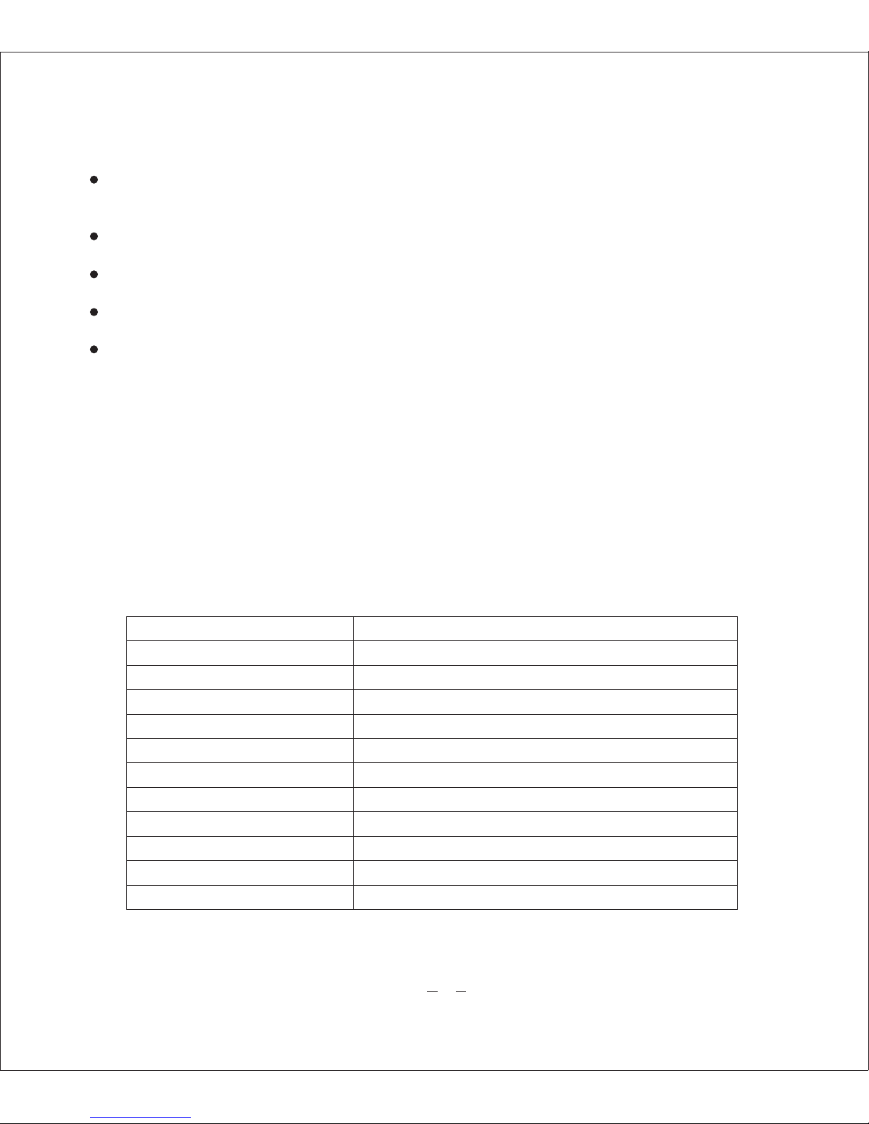
Reserved Preset Function
Go/Set Preset <95> Enters into OSD menu
Go Preset <80> Reserved.
Go Preset <82> Runs cruise function
Go Preset <83> Clean all presets
Go Preset <84 ~ 87> Runs Pattern 1 ~ 4
Go Preset <88> Reserved ( Runs wide dynamic function)
Go Preset <89> Reserved (Stop wide dynamic function)
Go Preset<96> Runs 360° scan(pause 3 seconds per 90°)
Go Preset <97> Runs linear scan
Go Preset <98> Runs cruise function
Go Preset <99> Runs Auto pan function
Page 12

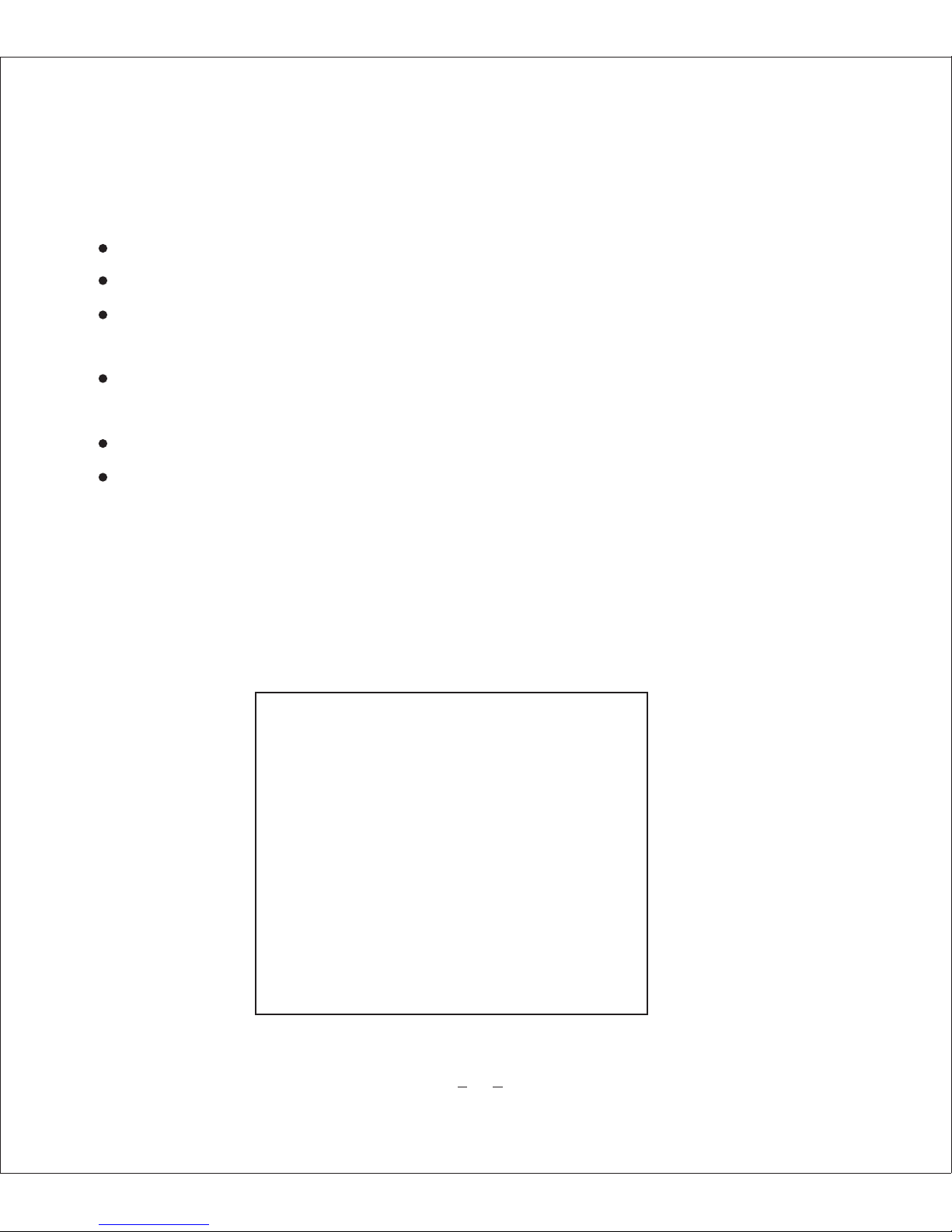
PTOL: PELCO-P
COMM:2400、N、8、1
ADDR: 1
10
3.3 Camera Lens control
3.3.1 Zoom
Adjust the lens distance to enlarge or downsize the image for best effect or wide-
angle effect.
Using “ZOOM IN / TELE” key to enlarge the images.
Using “ZOOM OUT/ WIDE” key to downsize the images.
3.3.2 Focus
Adjust definition of the object of scene
Press “Focus Far” key to shorten the distance of far scene.
Press “Focus Near” key to shorten the distance of near scene.
3.3.3 Iris
Press “Iris Open” key to adjust the brightness.
4.How To Use OSD Menu
After p ow er up o r restart , the p re se nt Protoc ol , Baud rate an d Addres s will be
displayed on the screen as below:
Page 13
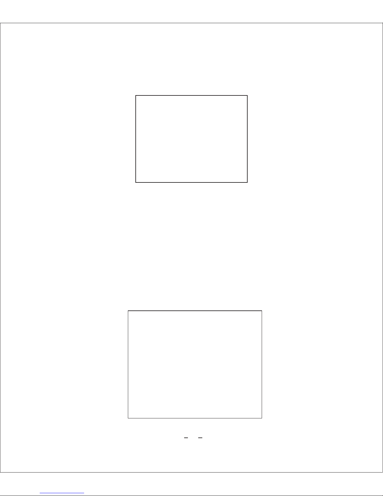
MAINMENU
SYSTEM INFORMATION
ADDR SETTING
MOTION
PATTERNS
CAMERA
CRUISE SETTING
DISPLAY SETUP ON
RESTORE FACTORY DEFAULT
REBOOT SYSTEM
EXIT
11
4.1 Basic operation of Main menu
4.2 Main menu
Note: There might display different information due to different camera.
Go <Preset 95> to enter into main menu.
Using “Iris open” and “Iris close” to confirm or exit main menu.
Using “UP/DOWN” keys or joystick to move cursor to sub-menu, press “Iris open” to
enter into menu.
Using “UP/DOWN” keys or joystick to move cursor to the function and press ”Iris open”
to choose the function.
Using “UP/DOWN” keys or joystick to set up and press “Iris open” to save.
Move the cursor to “BACK” and press “Iris open” to back to main menu.
Page 14

SYSTEM INFORMATION
COM 2400、N 8 1
ADDRESS 1
PROTOCOL PELCO-P
PRESETS 256
SOFTWARE VERSION V5.2
BACK
EXIT
、 、
12
<SYSTEM INFORMATION>:Shows system information.
<ADDR SETTING>:Select and setup Soft/Hard address.
<MOTION>:Setup for motion related settings.
<PATTERNS>:Setup for Patterns.
<CAMERA>:Configure Camera related functions and data.
<CRUISE SETTING>:Setup presets scan.
<DISPLAY SETUP>:Enable / Disable of OSD display on main screen.
<RESTORE FACTORY DEFAULT>:Restore factory settings.
<REBOOT SYSTEM>:Reboot the system.
4. 2. 1 System Information
Notice: the system information can not be changed.
<COM>:Shows current Baud rate.
<ADDRESS>:Shows current Camera ID for PTZ control, 0~255.
<PROTOCOL>:Shows current protocol for PTZ control.
<PRESETS>:Shows the preset numbers.
<SOFTWARE VERSION>:Shows current software version of camera.
Page 15
ADDR SETTING
ADDR TYPE HARD
ADDR SOFT 3
ADDR HARD 1
BACK
EXIT
MOTION
SET FRAME SCAN
POWER UP PATTERN 4
PARK TIME 15S
PARK ACTION PATTERN 4
FRAME SCAN SPEED 16
RNADOM SCAN SPEED 16
BACK
EXIT
13
4. 2. 2 Address Setting
ADDR TYPE:Choose the address type (Hard/Soft Add), when you choose soft type,
the user can setup the address by remote access.
ADDR SOFT:setup soft address . Press UP/DOWN” keys of your controller and setup
the camera ID from 0~254.
ADDR HARD: Setup hard address. Only can be changed by DIP Switch.
Notice: Please reboot the dome camera after reset the camera ID.
4.2.3 Motion
Page 16

14
Motion setup is to setup preset and packing action function.
SET FRAME SCAN:setup the LEFT/RIGHT extreme position between
two presets.
POWER UP :This function enables to resume the last action executed
before power down.
NONE : No action.
CRUISE: Cruise action between presets position.
AUTO SCAN: 360°continious scan.
RANDOM SCAN: 360°intermittemt scan action. FRAME SCAN:
PARK TIME : Parking action during idle time.
Time setting: 15-60 (Seconds) ,2…60M(Minutes), 2…12H(Hours)
PARK ACTION :This function enables to locate the camera to specific
position automatically
if operator doesn’t operate the controller for a while. The Park Time can
be defined as an interval.
FRAME SCAN SPEED: Set the speed between two presets from1~32.
RANDOM SCAN SPEED: set the speed of 360° continuous and
intermittent scan.
Page 17
FRAME SCAN
SET SCAN POSITION
CLEAR FRAME SCAN
BACK
EXIT
SET FFRAME SCAN
LEFT LIMIT POSITION
IRIS OPEN TO CONTINUE
15
Set Frame Scan
SET SCAN POSITION:Set up scan range between two positions (Left/Right extreme
position).
CLEAR FRAME SCAN:Deletes frame scan.
1. Set Scan Position
(1) Move the cursor to <Set Scan Position> and enter below interface.
(2) Move the cursor to choose the extreme position of preset by using “ Left / Right ” keys
or joystick of your controller, then press “Iris Open” to enter below interface:
Page 18
SET FFRAME SCAN
RIGHT LIMIT POSITION
IRIS OPEN TO CONTINUE
CLEAR FFRAME SCAN
IRIS OPEN TO CONTINUE
PATTERNS
PATTERN NUMBER
PROGRAM PATTERN
CLEAR CURRENT PATTERN
CLEAR ALL PATTERN
EXIT
BACK
16
2. Clear Frame Scan
Move the cursor to “Clear Frame Scan” to enter, the press “Iris Open” to delete the
extreme positions.
4.2.4 Patterns
4 Patterns are supported, please refer to below details:
<PATTERN NUMBER>:Set Pattern number (1~4).
<PROGRAM PATTERN>: Pattern scan program.
<CLEAR CURRENT PATTERN>:Deletes data in current pattern.
Page 19

PROGRAM PATTERN
USE THE JOYSTICK OR
KEYBOARD TO MOVE THE
CAMERA TO THE
STARTING POSITION
IRIS OPEN TO CONTINUE
P
A
TT
ERN
S
STORAG
E US
E
D
17
1.Pattern Number
(1)Move the cursor to “PATTERN NUMBER” by using direction keys and select pattern
number, then press “Iris OPEN” to confirm.
2. Program Pattern
(1)Move the cursor to “Program Pattern” by using direction keys or joystick of your
controller and press “IRIS OPEN” to enter below interface.
(2)Using keyboard or joystick of your controller to locate the start position, then press
“Iris Open” to enter.
(3)Using keyboard or joystick of controller to edit pattern route and action, Max 100
actions, then press “Iris Open” to save.
4.2.5 Camera setup
We are using Samsung SDM-100P camera to explain below operation.
Page 20
18
Main Menu
Camera label Off
White Balance Auto
BLC Off
Auto Detection Off
Focus
Exposure
Additional Menu
Back
Exit
Notice: Up/Down keys for option, “Left/Right” keys for details, “Iris Open”
for sub-menu.
“ ”
1.Camera Label setup:press “Iris Open” to enter sub-menu and edit camera lable.
Camera L abel
ABCDEF GHIJKLMNO
PQRSTU VWXYZabcd
e f g h I j k l m nopqrs
t u v w x y z01234 567
89 ( ) < > - / # * ! ? , .
Clean Po sition Exit
Using cursor to select the letter, then press “Iris Open” key to save the setup.
Page 21

19
2. White Balance setup
WB Mode: Auto Trace / Manual / Auto
2.1 Auto Trace : Indoor/Outdoor, The camera can automatically adjust ambient light
from 1800K~10500K(Indoor :3000~10,500K; Outdoor:1,800~10,500K,)to
ensure the most nature image effect.
Auto Trace WB
Auto Trace WB mode Outdoor
Exit
2.2 Manual: Close auto WB, adjust Red and Blue level manually.
Manual WB
Red 30…|..……….
Blue 41…..…|…….
Exit
Page 22

20
Red adjust range: 0~100 Blue adjust range: 0~100
2.3 Auto BW : This mode is the most accurate and reliable for most places.
3. Backlight Compensation setup
Backlight High/Middle/Low/Off
4.Motion Detection setup
Match the Alarm sensor input to one of preset positions. If an external sensor is
activated, camera will move to corresponding preset position when this item is
predefined.
Motion Detection
Alarm On/Off
Select Region 1
Region Mode On
Top 20…|..……….
Bottom 25….…|…….
Left 20…|.……….
Right 40….……|….
Exit
Alarm : On/Off
Region:1~4
Region Mode: On / Off
Page 23
21
5.Focus Setup
Focus
Mode Auto
Zoom trace mode On
Zoom trace speed Fast
Digital Zoom On
Show Zoom Off
Initial Zoom Position Off
Lens Initialization
Exit
1.Mode:Auto, Manual, One-off Auto f oc us . Press “Iris Open” t o enter sub-menu .
One-off auto focus: Once the image zoom changes, the camera will automatically
focus and fix the status till the image change again.
Notice: do not use Auto Focus under the below conditions.
The target is too dark (such as black clothes or curtains).
The target is very smooth( like car surface)
The brightness contrast of the target is not very clear.
Too strong high light or back light.
Too high contrast.
Some shade in front of the target.
(1) Auto mode setup:
Page 24
22
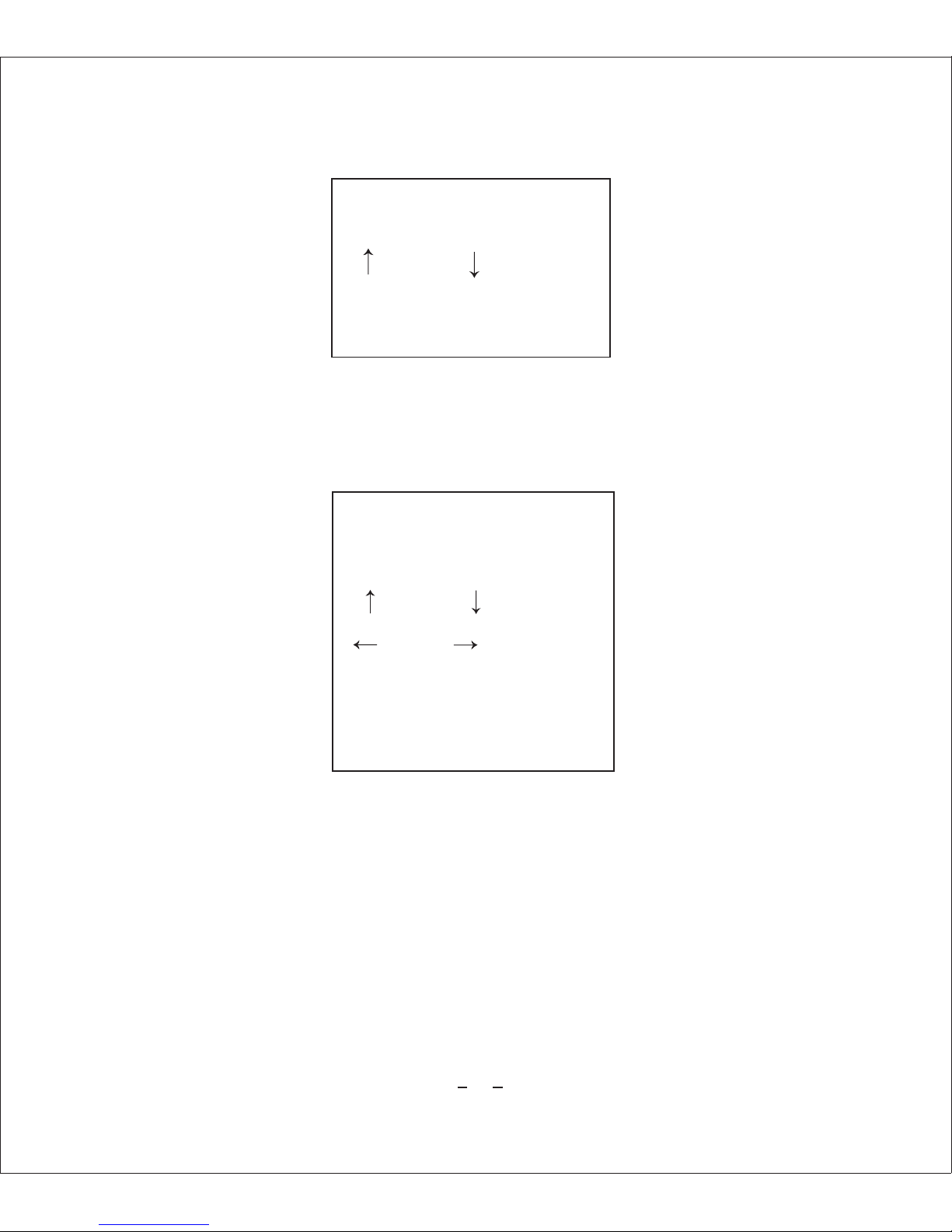
Setup Zoom
Zoom in Zoom out
Back : press “SET” key
Using the direction keys to enlarge or downsize, press “ Iris/Open” key to back.
(2) One-off Auto focus and Manual focus Adjustment:
Setup Zoom
Zoom in Zoom out
Near Far
Back : press “SET” key
2. Zoom trace mode:
Manual Focus: Off. Auto and One-off Auto Focus: On / Off.
3. Zoom trace speed: Fast/Slow.
4. Digital zoom: On / Off , range: X2~X10.
Page 25
23
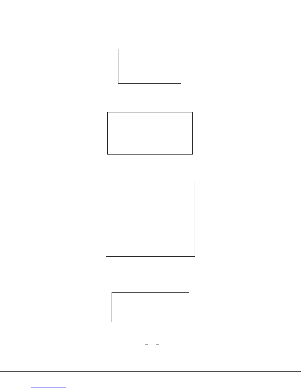
Digital Zoom
Digital Zoom X2
Exit
5.Show zoom: On / Off.
6.Initial zoom position:Using direction keys to move the cursor to “On”, then press
“Iris Open” to set up.
Initial Zoom Position
Initial Zoom Position X1
Exit
Zoom range: X1~X10
7. Lens Initialization: press “Iris open/Set” key to initialize the lens.
8. Exposure setup:
Exposure
Brightness 25….…|…….
Iris Auto
Shutter ——
AGC Off
SSNR Off
SENS-UP Off
Exit
Brightness range: 0~100.
Iris:Auto/ Manual. Press “Iris Open” to enter into manual setup
Manual Iris
Iris 100….………|
Exit
If the number of iris is set to higher, the image will be brighter.
Page 26

24
Shutter mode: Flicker / Manual / Auto
The shutter speed of Anti-flash is 1/100(NTSC) ,1/120(PAL)
Manual mode setting (PAL):2X、4X、6X、8X、10X、12X、14X、16X、24X、32X、
64X、128X、1/120000、1/60000、1/30000、1/10000、/ 1/7000、1/5000、1/2500、
1/1600、1/1000、1/700、1/500、1/250、1/100、1/50.
Manual shutter
Shutter 1/50
Exit
Notice: Auto shutter setting only for manual iris mode.
AGC: High / Middle/ Low / Off.
Enhances image brightne ss automa ti ca ll y in ca se that luminanc e level of ima ge
signal is too low.
Range: 5-41
AGC
Level 5
Exit
SSNR:High / Middle / Low / Off
Enhances images by reducing noises when gain level of images too high.
Sens-up: Manual / Off
Adjust CCD exposure time.
Auto mode setting:2X、4X、6X、8X、10X、12X、14X、16X、24X、32X、64X、128X.
Page 27

25
Sens-up
Sens up X4
Exit
9 .Additional menu:
Additional menu
User setup Off
Privacy zone mask Off
Day & Night Auto 1
Sync. system Internal
Image adjustment
EXIT
( 1 )User preset setup: On / Off
User Preset
User preset number No 1
User preset mode Off
Save
Clear
Exit
preset not setup.
8 user preset number, 1~8.
User Preset mode: use direction keys to “On” and press “Iris/Open” to setup.
Page 28
26
User preset mode
Focus
Exposure
Other
Exit
Focus: Using direction keys to “Focus” and press “Iris/Open” key to set up.
Focus
Mode Auto
Zoom trace mode On
Zoom trace speed Fast
Digital zoom On
Show zoom Off
Exit
Other:refer to below details.
Other
Camera Type Off
BW Auto trace BW
BLC Off
Motion Detection Off
Privacy mask Off
Day & Night Outer
Horizontal flip Off
Vertical flip Off
Exit
Page 29

27
(2) Privacy mask
Privacy mask
Group selection 1
Area selection 1
Zone mode Off
Color 50…|..……….
Top 50…|..……….
Bottom 104….…|…….
Left 50…|.……….
Right 98….……|….
Exit
Group selection:1~ 8
Area selection: 1~4 zone / group
Zone mode: On / Off
Color: color, range of privacy zone is 0~100.
Top: ordinate position on the top of zone.
Bottom: ordinate position on the bottom.
Left: horizontal abscissa position on the left side.
Right: horizontal abscissa position on the left side.
(3) Day / Night: Day an d Night function . Auto 1/ Au to 2 / Outer/ Color/ B&W m o de .
B&W mode: suit for night work.
Color mode: suit for daytime.
Auto mode: change day and night mode automatically according to the environment
illumination. Auto 1 is faster than Auto 2.
Page 30

28
(4) Synchronous mode: internal, unchangeable.
(5) Image adjustment.
Image adjustment
Freeze Off
Horizontal flip Off
Vertical flip Off
Sharpness On
Hue 50….…|…….
Exit
Freeze : Camera starts freezing the image of start point , as soon as camera stops
at preset end point, camera starts display live images.
Horizont a l flip : image will flip 1 80 ° when you sta rt up . Normal when shutdown .
Vertica l flip: image will s li p 180°whe n you s ta rt up, and nor ma l when shutdown.
Sharpness: adjust the sharpness of the edges. Range: 0~31.
Sharpness
Sharpness 8…|.……….
Exit
Hue: adjust the image hue, range: 0~100.
Re-boot: restart the camera.
Exit: exit camera menu.
4.2.6 Cruise Setting.
Page 31
29
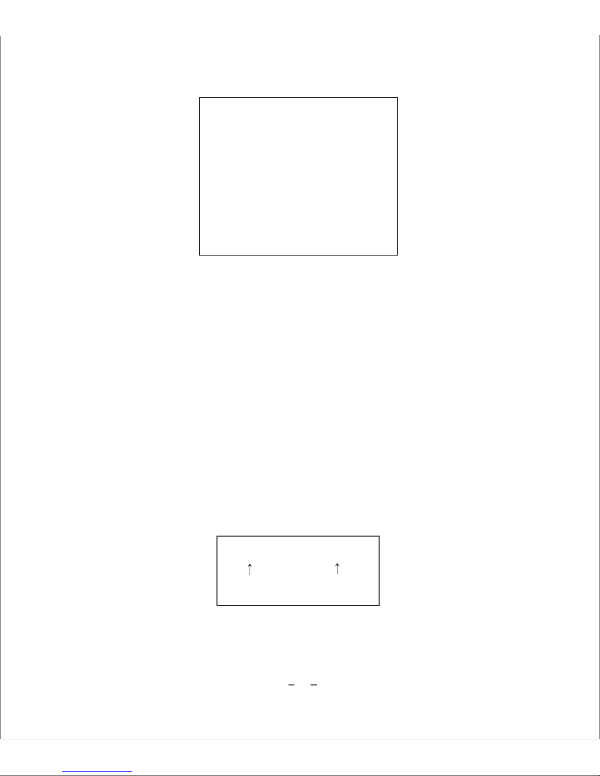
CRUISE
DWELL TIME<SECS> 6
PRESET LIST 1
1 ON 0 OFF
1234567890 PRESET
1101111111 [1-10]
BACK
EXIT
Auto cruise : set up preset scan route.
< Dwell Time (Sec)>: preset cruise dwell time, range:1~250 Sec.
< Preset List>: 3 pages.30 presets.
< 1234567890>:preset position in the preset list.
< 110111 1111>:1 means the preset position corresponding to above preset list is
elected to cruise list; 0 means overleap.
< Back>:save the setup and back to main menu.
<Exit>:Exit OSD menu
4.2.7 Display Setup
Display setup: On/Off, set up the orientation display or not.
Horiz ontal /Vertic al Zoom
236/163 X1
4.2.8 Restore Factory Default.
Move cursor to <RESTORE FACTORY DEFAULT> and press “Iris/Open to restore
factory default.
Page 32
30
4.2.9 Reboot System>
Move cursor to <Reboot System > and press “Iris /Open” to reboot the system. Easy
to change the Soft/Hard address by remote and no need to power off.
4.2.10 Exit: Move cursor to <Exit> and press “Iris /Open” to exit the OSD menu.
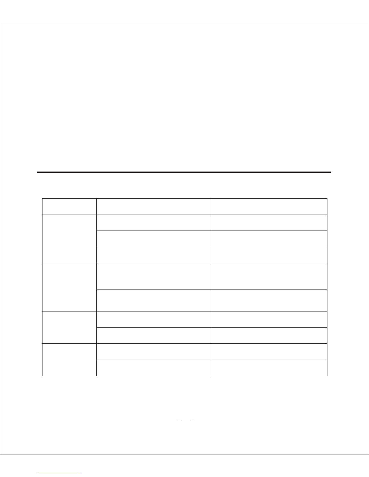
5.Trouble Shooting
Troubles Reason Solution
Connect wrong cable. Correct the connection
Power supply damaged. Change
Bad connection Eliminate the bad connection
Video cable is bad connection Eliminate the bad connection
Power is not enough. Change
Check RS-485 connection cable
RS-485 cable broken Check RS-485 connection cable
RS-485 cable is bad connection
or disconnection
RS-485 c able revers e connectio n
or disco nnection.
Maybe user setup wrong IP,
Protocol and Baud rate.
Reset IP, Protocol and Baud rate
Check RS-485 connection cable
No action, no
image after
power on
Out of control
after power
up
Screen not
stable
Discontinuity
while work
Page 33

31
6.Safety Information
1. Transportation
Do not force, shake and marinate during transportation, storage and installation.
2. Installation
Please handle with care, do not press the camera and its' parts when you install,
do not connect before you install the cover.
3. Power cable, Video cable and control cable.
Use shield wire and do not mix with other cables.
4 Electrical safety
Keep the camera or signal transmission wire away from high voltage equipment
or cable (at least 50 meters), take lightning protection and surge protection.
5. Clean
When cleaning , use dry and soft cloth or neutral cleanser to clean the camera cover.
6.Must be sealed closely , do not spray water or liquid onto parts of camera , doing
so may cause damage.
7. Do not use the camera in extreme temperature or humidity environment.
8. Do not install the camera close to air outlet of air condition.
Camera lens will be misty because of water condensation under below conditions:
Extreme temperature change.
The room full of smoking or dust.
9. Do not locate the camera towards extremely bright objects such as sun and
spotlight, as this may damage the CCD image sensor.
Page 34

 Loading...