

Esu LokSound Select, LokSound V4.0 Quick Start Manual

Quick Start Guide
LokSound Select
LokSound V4.0
Technical Data for LokSound Select and LokSound V4.0 Decoders
Operational modes
NMRA/DCC with 14, 28, 128 speed steps.
2-digit (short) and 4-digit (long) addresses.
Analog DC operation (de-selectable).
Automatic recognition of operational mode and DCC speed step selection.
Power
Runs all DC and coreless motors.
Silent, safe 31,25 kHz pulse width frequency BEMF
Motor output overload protection
8 pin and 21MTC decoders 1.10A continuous load / 2.00 A peak load
Next18 / Select Micro and V4.0 decoders 0.75A continuous load / 1.00 A peak load
Function outputs
8 pin Select and V4.0 decoders Up to 6 outputs (6 powered)
21MTC Select and V4.0 decoders Up to 8 outputs (4 powered, 4 logic)
Next18 / Select Micro and V4.0 decoders Up to 6 outputs (4 powered, 2 logic)
Sound
Audio amplifier: 2W @ 4 Ohm load
Speaker impedance 4 - 16 Ohms
Memory capacity 32 MBit
8 sound channels, all playable at once!
Over 20 different sounds!
Programming
Features
DCC Servicemode & DCC POM (Programming on Main).
RailCom® Feedback system. RailComPlus® automatic Registration.
CV Name Description Range
Default
1 Loco address Short (2 digit) address of locomotive 1 - 127 3
2 Start voltage Minimum speed of the locomotive 1 - 255 3
3 Acceleration This value multiplied by 0.25 is the time from stop to maximum speed 0 - 255 80
4 Deceleration This value multiplied by 0.25 is the time from maximum speed to stop 0 - 255 80
5 Maximum speed Maximum speed of the locomotive 0 - 255 255
6 Medium speed Medium speed of locomotive 0 - 255 88
8 Manufacturer‘s ID Manufacturers‘s ID ESU - Writing value 8 in this CV triggers a reset to
factory default values
151 -
17 & 18Long address of the loco Long address of engine ( see full manual online at www.loksound.com)
19 Consist Address Additional address for consist operation. Value 0 or 128 means: consist
address is disabled
1 – 127 consist address active, normal direction
129 – 255 consist address active reverse direction
0-255 0
27 Brake mode Allowed brake modes 28
Bit Function Value
0 ABC braking, voltage higher on the right hand side 1
1 ABC braking, voltage higher on the left hand side 2
2 ZIMO® HLU brakes active 4
3 Brake on DC, if polarity against driving direction 8
4 Brake on DC, if polarity like driving direction 16
7 Loco brakes with constant brake distance, if FS=0 128
28 RailCom® Configuration Settings for RailCom® 131
Bit Function Value
0 Channel 1 Address broadcast enabled 1
1 Data transmission allowed on Channel 2
7 RailCom® Plus automatic loco recognition active 128
29 Configuration register Calculated field. Add up the values you want to activate, then write this
number into CV 29.
12
Bit Function Value
0 Normal direction of travel
Reversed direction of travel
0
1
1 14 speed steps DCC
28 or 128 speed steps DCC
0
2
2 Disable analog operation
Enable analog operation
0
4
3 Disable RailCom®
Enable RailCom®
0
8
4 Speed curve through CV 2, 5, 6
Speed curve through CV 67 - 94
0
16
5 Short addresses (CV 1) in DCC mode
Long addresses (CV 17 + 18) in DCC mode
0
32
31 Index register H Should be either “0” or “16” for LokSound Decoders 16 16
CV Name Description Range
Default
32 Index register L CV 32=0 if accessing CVs 1- 255, CV 31=1,2,3 if accessing CVs 257-511 0 - 4 0
48 Master Sound Select Selects the prime mover sound (0, 16, 32, 64), the horn (0-15), the bell
(0,64), Brake Squeal Sound (0, 128) - add the numbers up for each selection to get the final value of CV 48. Will vary between sound files. Locate
the sound file description on our web site for valid values.
0 - 255
49 Extended
Configuration #1
0 Enable Load control (Back-EMF)
Disable Load control (Back-EMF)
100 - 255 19
1 DC Motor PWM frequency
20kHz motor pulse frequency
40 kHz motor pulse frequency
0
2
2 Reserved
0
0
3 Reserved 0
4 Automatic DCC speed step detection
Disable DCC speed step detection
Enable DCC speed step detection
0
16
5 LGB® function button mode
Disable LGB® function button mode
Enable LGB® function button mode
0
32
6 Reserved
0
64
7 Reserved
0
128
50 Analogue mode Selection of allowed analogue modes 0 - 3 3
Bit Description Value
0 AC Analogue Mode ( Only LokSound V4.0)
Disable AC Analog Mode
Enable AC Analog Mode
0
1
1 DC Analogue mode
Disable DC Analogue mode
Enable DC Analogue Mode
0
2
61 Random sound «min» Multiplied by 0.25 it is the time in seconds for the shortest random
sound interval. F
0 - 255 120
62 Random sound «max» Multiplied by 0.25 it is the time in seconds for the longest random sound
interval.
0 - 255 200
63 Sound volume «Master» Master volume for all sounds. 0 - 192 192
64 Brake sound threshold
«Brake On»
If the actual loco speed step is smaller than or equals the value indicated
here, the brake sound is triggered.
0 - 255 100
65 Brake sound threshold
«Brake Off»
If the actual loco speed step is smaller than the one indicated here (up to
255), the brake sound will be switched off again. .
0 - 255 25
66 Forward Trim Divided by 128 is the factor used to multiply the motor voltage when
driving forward. The value 0 deactivates the trim.
0 - 255 128
67-94Speed table Defines motor voltage for speed steps. The values „in between“ will be
interpolated.
0 - 255 -
CV Name Description Range
Default
95 Reverse Trim Divided by 128 is the factor used to multiply the motor voltage when
driving backwards. Value 0 deactivates the trim.
0 - 255 128
113 Power Fail Bypass The time that the decoder bridges via the PowerPack after an interrup-
tion of voltage. Unit: A multiple of 0.016384 sec.
0 - 255 50
124 Extended Configura-
tion #2
Additional important settings for decoders - 24
Bit Description Value
0 Bi-directional bit: Enable driving direction when shifting
direction.
Disable driving direction.
1
0
1 Disable decoder lock with CV 15 / 16
Enable decoder lock with CV 15 / 16
0
2
2 Disable prime mover startup delay
Enable prime mover startup delay
0
4
3 Disable serial protocol for C-Sinus
Enable serial protocol for C-Sinus
0
8
4 Adaptive regulation frequency
Constant regulation frequency
0
16
5 Motor safety when blocking.
Motor is not switched off when blocked.
Motor is switched off for a few seconds when blocked to
avoid burnout
0
32
125 Starting voltage Analog
DC
0 - 255 30
126 Maximum speed Analog
DC
0 - 255 130
127 Starting voltage AC (ONLY for LokSound V4.0) 0 - 255 50
128 Maximum speed Analog AC(ONLY for LokSound V4.0) 0 - 255 150
134 ABC-Mode „Sensibility” Threshold, from which asymmentry on ABC shall be recognised. 4 - 32 12
See the full manual online at www.loksound.com
Warnings
• Do not expose to wet and humid conditions.
• Avoid mechanical force or pressure on the decoder.
• Only use the minimum amout of solder needed.
• Always disconnect power before handling the decoder.
• Never wrap the decoder in electrical tape, as this
may cause overheating.
• Make sure that neither the decoder nor any blank
wire ends may come into contact with the engine
chassis (risk of short circuit).
• Make sure that no wires are squeezed / cut when
reassembling the locomotive.
• Never operate a LokSound decoder unattended.
Requirements for Installation
The locomotive must be in perfect operating condition prior to the conversion: Only a locomotive
with faultless mechanical properties and smooth
running characteristics in analogue mode is worth
converting to digital. Check and replace all wear
and tear parts such as motor brushes, wheel contacts, light bulbs etc., if necessary.
Installing the Decoder
Locomotives with 8-pin interface
Some LokSound decoders are supplied with an
8-pin plug (refer to Fig 1). Remove the dummy
plug from the socket. Insert the plug of the decoder in such a way that pin 1 of the plug (this is the
side with the red / orange wires) sits next to the
corner of the socket that is usually marked with
*, +, • or “1”.
Do not rely on the assumption that the wires of the
harness have to face in a certain direction: the only
reliable reference is the marking of pin 1.
Locomotives with 21MTC interface
Some LokSound decoders are equipped with a
21MTC interface (fig. 2) You can insert the decoder in two ways: either the pins are put through
the decoder (most common); the socket of the
decoder remains visible after installation (mounting
on top) or the decoder is inserted in such a way that
the pins go straight into the socket. Which of the
two mounting positions is the correct one depends
solely on the locomotive. The position of the marker-pin is the crucial indicator. Plug the decoder into
the socket in such a way that the locomotive interface corresponds with the decoder. Do not apply
too much pressure when inserting the plug. The
decoder must go in without force.
Fig. 1: LokSoun with 8-pin interface
Pin Description Color
1 Right motor terminal orange
2 Rear light yellow
3 Output AUX1 green
4 Left track terminal black
5 Left motor terminal gray
6 Head light white
7 Common (+pole) blue
8 Right track terminal red
5 4
1
Wheel sensor 1
n.c. 2
AUX6 3
AUX4 4
ZBCLK 5
ZBDTA 6
Rearlight 7
Headlight 8
Loudsp. #1 9
Loudsp. #2 10
Index-pin 11
Figure 2: LokSound with 21MTC interface
22 Right track
21 Left track
20 GND
19 Right motor
18 Left motor
17 AUX5
16 Common (+)
15 AUX1
14 AUX2
13 AUX3
12 VCC
How to connect the decoder:
connector
to the top
Locomotive pcb
(Side view)
Locomotives without interface
All LokSound decoders have an interface (plug).
There is no “wires-only” version. Please remove
the plug at the end of the harness should hard
wiring become necessary.
First, please cut all wires installed in the locomotive. Take special care to remove any connections
to the chassis (ground): the motor leads must be
positively potential-free, in other words they may
not have any contact to the chassis or body or the
wheels and wheel contacts. Figure 3 and Figure 4
shows all connections.
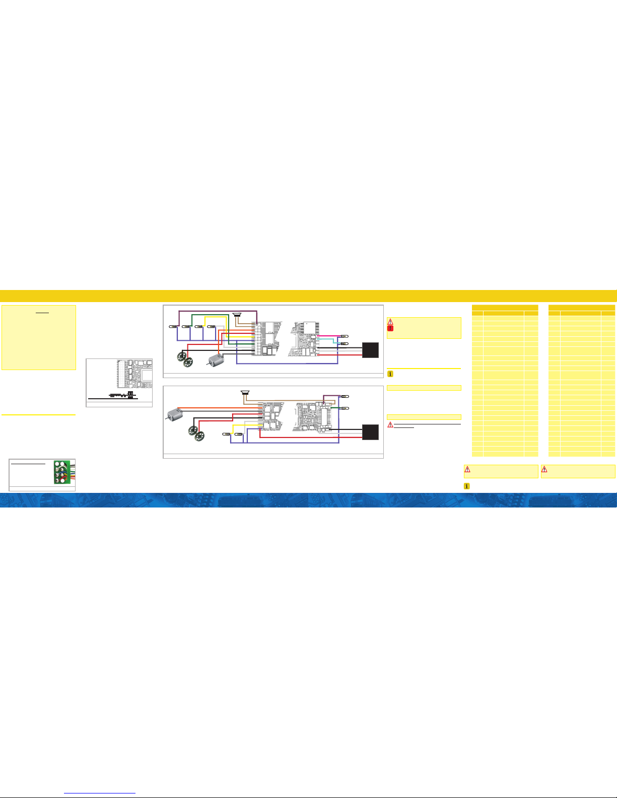
Figure 3: LokSound Decoder - Wiring Diagram
violet
DC motor
AUX2 AUX1
Rearlight
Head-
light
violet green yellow white
grey
orange
Left track
connection
Right track
connection
red
black
brown
brown
blue
blue
green
white
black
grey
yellow
red
orange
Loudspeaker
4~8 Ohms
Decoder FRONT Decoder BACK
blue (Decoder common)
pink
AUX3
AUX4
turquoise
U+
red
white Charge
GND
black
ESU
Power
Pack
Figure 4: LokSound micro Decoder - Wiring Diagram
DC motor
AUX2
AUX1
Head-
light
violet
green
yellow
white
grey
orange
Left track
connection
Right track
connection
red
black
brown
Loudspeaker
4~8 Ohms
brown
black
white
yellow
blue
red
grey
orange
Decoder FRONT
Decoder BACK
U+
Charge
GND
ESU
Power
Pack
blue (Decoder common)
Function outputs
You can wire all kind of loads to the function outputs.
Please make sure that the load does not exceed
the permitted maximum current and there are
no short circuits. The outputs of the LokSound
have protection but if an external voltage is
applied, the outputs may suffer damage or destruction.
Only install bulbs rated 16V or higher and with a
nominal current draw, that does not exceed 50
mA. If you like to use LEDs, a resistor with a rating
between 470 Ohms and 2.2 kOhms need to be
wired in series. Running the LED without resistor
will lead to their immediate destruction!
DCC Operation
The LokSound works with any DCC system.. Remove any capacitors that are wired into the track
feeders. This could impair the functionality of the
decoder.
The address is set to 03 with 28 speed steps.
Decoder Reset
You can reset the decoder to the default settings
at any time. In most cases POM programming will
not work to reset a decoder. Please use a separate
programming track.
Enter the value 08 into CV 08.
To complete the reset, power to the decoder must
be interrupted.
Volume Control
Master volume is controlled with CV 63. The range
is 0 - 192.
Individual volumes (CVs as shown) range from
0 - 128
Default Function Assignment - DIESEL
Function Effect Volume CV
F0 Directional Headlights -
F1 Bell 283
F2 Playable Airhorn 275
F3 Coupler 291
F4 Dynamic Brake 299
F5 AUX3 (Rotary Beacon) -
F6
AUX1 + AUX2 (Front
Ditchlights)
-
F7 Switching Mode -
F8 Sound (On / Off) 259
F9 Drive Hold -
F10
Locomotive (Independent)
Brake
-
F11 Radiator (Fan) Sound 315
F12 Dimmer (Headlights) -
F13 AUX4 (Rear Ditchlights) -
F14 - -
F15 Fast Spitter Valve 371
F16 Spitters on Shutdown -
F17 Brake Set / Brake Release -
F18 Sanding Valve 355
F19 Short Air Let Off 363
F20 Compressor 307
F21 Slow Spitter Valve 387
F22 Air Dryer 427
F23 - -
Random Sounds 461
Brake Squeal 459
Default Function Assignment - STEAM
Function Effect Volume CV
F0 Directional Headlights -
F1 Bell 283
F2 Whistle 275
F3 Coupler 291
F4 Coast Mode -
F5 AUX3 (Mars light) -
F6 AUX2 (Cab Light) -
F7 Manual Cylinder Cocks 427, 435
F8 Sound (On / Off) 259, 443
F9 Heavy Load Mode -
F10
Locomotive (Independent)
Brake
-
F11 Coal Shoveling 371
F12 Dimmer -
F13 AUX4 (Class Lights) -
F14 Air Pump Variable Speed 307
F15 Air Pump Slow 411
F16 Injector 323
F17 Auto Brake Set / Release Off -
F18 Ash Dump 355
F19 Blowdown 403
F20 Savety Valve 331
F21 Airhorn 419
F22 Grade Crossing Sequence 379
F23 Oil Headlights (No dynamo) -
Random Sounds 461
Brake Squeal 459
Make sure that Index CV 31 is set to 16 and
Index CV 32 is set to 1 before changing a
volume CV
Make sure that Index CV 31 is set to 16 and
Index CV 32 is set to 1 before changing a
volume CV
All function buttons are fully mappable. This allows you to customize your Function Assignments in any way
you wish. Please see our full manual for information on how to arrange this.
 Loading...