

Esu LokPilot V4.0, LokPilot micro V4.0 DCC, LokPilot V4.0 M4, LokPilot XL V4.0, LokPilot Fx V4.0 Instruction Manual
...
Instruction Manual
6. Edition, February 2013
P/N 51986
LokPilot V4.0
LokPilot V4.0 DCC
LokPilot micro V4.0
LokPilot micro V4.0 DCC
LokPilot V4.0 M4
LokPilot XL V4.0
LokPilot Fx V4.0
LokPilot V4.0

2
1. Declaration of Conformity ...................................... 5
2. WEEE-Declaration ....................................................5
3. Important Notes – Please read this chapter first ... 5
4. How this manual helps you .................................... 6
5. Introduction – The LokPilot Family ......................... 7
5.1. Overview of the LokPilot V4.0 decoders ........................7
5.2. Members of the LokPilot Family ....................................8
5.2.1. LokPilot V4.0 .............................................................8
5.2.2. LokPilot V4.0 DCC .....................................................8
5.2.3. LokPilot micro V4.0 ...................................................8
5.2.4. LokPilot micro V4.0 DCC............................................8
5.2.5. LokPilot XL V4.0 .........................................................8
5.2.6. LokPilot V4.0 M4 .......................................................8
5.2.7. LokPilot Fx V4.0 .........................................................9
5.2. General Properties of all Decoders.................................9
5.2.1. Operating Modes .......................................................9
5.2.2. Motor Control ...........................................................9
5.2.3. Analogue Mode .......................................................10
5.2.4. Functions .................................................................10
5.2.5. Programming ...........................................................10
5.2.6. Operational Reliability ..............................................10
5.2.7. Protection ................................................................10
5.2.8. Future built-in ..........................................................10
6. Installing the Decoder ...........................................11
6.1. Requirements for Installation .......................................11
6.2. Installing the Decoder .................................................11
6.3. Locomotives with 8-pin NEM 652 interface .................11
6.4. Locomotives with 6-pin NEM 651 interface .................12
6.5. Locomotives with 21MTC interface .............................12
6.5.1. Connecting C-Sine motors („SoftDrive-Sinus“) ........13
6.6. Loks mit PluX-Schnittstelle ..........................................14
Content
6.7. Locomotives with Next18 interface .............................14
6.8. Locomotives without interface ....................................14
6.8.1. Wiring Diagram for LokPilot .....................................14
6.8.2. Wiring Diagram for LokPilot micro ...........................15
6.8.3. Wiring Diagram for LokPilot Fx .................................15
6.8.4. Wiring diagram for LokPilot XL decoders .................16
6.8.4.1. Wiring to LGB® gear boxes ..................................16
6.8.4.2. Wiring to an LGB® interface .................................17
6.8.4.3. Wiring to the Aristocraft® interface ......................17
6.8.5. Colour Coding by Märklin® ....................................18
6.8.6. Motor and track connections ...................................18
6.8.6.1. Connecting DC and Coreless Motors ....................18
6.8.6.2. Connecting Univers. Motors with HAMO-Conversions 1 9
6.9. Connecting Additional Functions ................................19
6.9.1. Overload Protection of Function Outputs (Blinking) . . 19
6.9.1.1. Suitable light bulbs ...............................................19
6.9.1.2. Micro incandescent lamps wired to LokPilot XL .....19
6.9.2. Using LEDs ...............................................................20
6.9.3. Connecting the Light Outputs, AUX1 and AUX2 ......21
6.9.4. Using AUX3 and AUX4 ............................................21
6.9.4.1. LokPilot with 21MTC interface ..............................21
6.9.4.2. LokPilot with PluX16 interface ..............................21
6.9.4.3. LokPilot Fx V4.0 ....................................................21
6.9.5. AUX5 to AUX 6 ......................................................21
6.9.5.1. Servo outputs .......................................................22
6.9.6. Suitable Smoke Generators ......................................22
6.9.7.1. HALL Sensor IC .....................................................22
6.9.7.2. Reed switch sensor ...............................................23
6.10. Connecting Capacitors..............................................23
6.10.1. LokPilot H0, LokPilot micro decoders ......................23
6.10.2. Optional “PowerPack” .........................................24
7. Initial Operation ..................................................... 25
7.1. Factory Default Values .................................................25
7.2. Digital Operating Modes .............................................25
7.2.1. DCC-Betrieb ............................................................25
7.2.1.1. DCC Speed Steps („flashing lights“) .....................25
7.2.1.2. Auto-detection of DCC Speed Steps .....................26

3
7.2.2. Motorola® mode .....................................................26
7.2.2.1. 28 Speed Steps .....................................................26
7.2.2.2. Extended Motorola® address range ......................26
7.2.3. Selectrix® mode ......................................................27
7.2.4. M4 mode .................................................................27
7.3. Analogue mode ..........................................................27
7.3.1. Analogue DC operation ...........................................27
7.3.2. Analogue AC operation ...........................................28
8. Decoder Settings (Programming) ........................ 28
8.1. Adjustable Properties of Decoders ..............................28
8.1.1. M4 configuration range ...........................................29
8.1.2. M4, the mfx® compatible protocol by ESU ..............29
8.1.1. Configuration Variables (CVs) ..................................30
8.1.1.1. Standardisation in the NMRA ................................30
8.1.1.2. Bits and Bytes .......................................................30
8.2. Programming with popular digital systems ..................30
8.2.1. Programming with DCC Systems .............................31
8.2.2. Programming with the ESU ECoS .............................31
8.2.3. Programming with Märklin® 6021 ..........................31
8.2.3.1. Changing to the Programming Mode ...................32
8.2.3.2. Short Mode ..........................................................32
8.2.3.3. Long Mode ...........................................................32
8.2.4. Programming with the Märklin® Mobile Station® ...33
8.2.5. Programming with the Märklin® Central Station .....33
8.2.6. Programming with the ESU LokProgrammer ............34
8.2.7. Programming with the ROCO® Multimaus ............34
8.2.8. Programming with the ROCO® LokMaus II ..............35
9. Address Settings .................................................... 36
9.1. Short Addresses in DCC mode ....................................36
9.2. Long Addresses in DCC mode .....................................36
9.3. Motorola® address .....................................................36
9.3.1. Consecutive addresses for more functions ...............36
9.4. Addresses in M4 mode ...............................................37
9.5. Turning off data protocols not needed ........................37
10. Adapting the Driving Characteristics ................. 38
10.1. Acceleration and deceleration ...................................38
10.1.1. Switching acceleration / deceleration .....................38
10.1.2. Shunting mode ......................................................38
10.2. Starting Voltage, Maximum and Medium Speed .......38
10.3. Speed Curve ............................................................39
10.4. Changing between operating modes .......................39
10.4.1. Changing from Digital to Analogue DC ................39
10.4.2. Changing from Digital to Analogue AC ................40
10.4.3. Changing from Analogue to Digital (Directional Bit) 40
10.4.4. Changing from Digital to Digital ...........................40
10.4.5. Changing modes with analogue mode turned off . . 40
10.5. Brake sectors ............................................................41
10.5.1. DC brake mode .....................................................41
10.5.2. Märklin® brake mode ............................................41
10.5.3. Selectrix® Diode Brake Sector ................................41
10.5.4. Lenz® ABC brake mode ........................................41
10.5.4.1. ABC “slow approach” section ............................42
10.5.4.2. ABC detection threshold .....................................42
10.6. Constant brake distance ..........................................42
10.6.1. Linear braking distance ..........................................43
10.6.2. Constant Linear Braking Distance ...........................43
10.6.3. Push-pull trains ......................................................43
10.6.4. Braking at speed step 0..........................................43
10.7. Settings for analogue operation ................................43
10.7.1. DC analogue operation ..........................................43
10.7.2. AC analogue operation ..........................................44
10.8. Motor brake .............................................................44
10.9. Configure the PowerPack „Switch off“ time .............44
11. Motor Control ......................................................45
11.1. Adjusting load compensation ....................................45
11.1.1. Parameter for frequently used motors ....................45
11.1.2. Adjustments for other motors / „Fine Tuning“ .......45
11.1.2.1. Parameter „K“ ....................................................45
11.1.2.2. Parameter „I“ .....................................................45
11.1.2.3. Reference voltage ...............................................46
11.1.2.4. Parameter “K slow” ............................................46
11.1.2.5. Parameter „I slow“ .............................................46
Content

4
11.1.2.6 Adaptive Regulation Frequency ............................47
11.1.3. Automatic calibration of the motor ........................47
11.2. Turning off Load Compensation ................................47
11.3. Adapting Load Control Frequency .............................47
11.4. Dynamic Drive Control: Up and Down the Hill...........47
11.5. Settings for the C-Sinus motor ..................................48
12. Function outputs .................................................. 49
12.1. Physical function outputs ..........................................49
12.2. Allocation of function buttons (Function Mapping) ...49
12.2.1. Index CV access .....................................................49
12.2.2. Function Mapping chart .........................................49
12.2.2.1. Conditions block .................................................51
12.2.2.2. Physical function outputs ....................................52
12.2.2.3. Logical outputs ...................................................53
12.2.2.4. „Virtual driving sound” .......................................54
12.2.3. Standard mapping LokPilot V4.0 / micro Decoder ..54
12.2.3.1 Example ...............................................................55
12.2.4. Allocation of function keys with the LokProgrammer 5 5
12.3. Special Effects on function outputs ...........................58
12.3.1. Switching on outputs and different options ...........58
12.3.2. Adjusting effects desired ........................................59
12.3.3. Grade Crossing holding time..................................60
12.3.4. Flash rate ...............................................................60
12.3.5. Automatic Switch-off .............................................60
12.3.6. Switch-on and switch-off delay ..............................61
12.3.7. Digital couplers ......................................................61
12.3.7.1. „Coupler“ mode ..............................................61
12.3.7.2. Automatic Coupler Function (Removing/Pushing) 61
12.3.8. Servo settings ........................................................61
12.3.8.1. Servo with coupler function ................................62
12.4. Analogue settings .....................................................62
12.5. LGB® Pulse Sequence Mode .....................................62
12.6. Swiss Head Light Mode .............................................63
13. Decoder Reset ......................................................63
13.1. With DCC Systems or 6020/6021 .............................63
13.2. With Märklin® systems (mfx® decoders) ..................63
Content
13.3. With the ESU LokProgrammer ...................................63
14. Special Functions .................................................. 64
14.1. Directional Bit ...........................................................64
14.2. Saving the status of functions ...................................64
15. RailCom® .............................................................. 64
15.1. RailComPlus® ...........................................................65
15.1.1. Prerequisites for RailComPlus® ..............................65
16. Firmware Update ................................................. 65
17. Accessories ........................................................... 65
17.1. Change over skis .......................................................65
17.2. HAMO magnets ........................................................65
17.3. Wire harnesses with 8-pole or 6-pole socket .............66
17.4. Mounting adapter 21MTC ........................................66
18. Support and Assistance ....................................... 66
19. Technical data ....................................................... 67
20. List of all supported CVs ..................................... 68
20.1. DCC decoders ...........................................................68
21. Appendix .............................................................. 73
21.1. Programming long addresses ....................................73
21.1.1. Write address .........................................................73
21.1.2. Read out address ...................................................73
22. Warranty Certificate ........................................... 75
5
1. Declaration of Conformity
We, ESU electronic solutions ulm GmbH & Co. KG, Edisonallee
29, D-89231 Neu-Ulm, Germany, declare in sole responsibility that
the product
Product description: LokPilot V4.0, LokPilot V4.0 DCC, LokPilot micro V4.0, LokPilot micro V4.0 DCC, LokPilot V4.0 M4,
LokPilot XL V4.0, LokPilot Fx V4.0
Part number: 54610, 54611, 54612, 54613, 54614, 54615, 54616,
54617, 54683, 54684, 54685, 54686, 54687, 54688, 54689, 54640,
64610, 64614, 64616, 64617, 54620, 54621
complies with all relevant regulations of the Directive for Electromagnetic Compatibility (2004/108/EG). The following harmonised
standards have been applied:
EN 55014-1:2006 + A1:2009: Electromagnetic Compatibility requirements for household appliances, electric tools, and similar
apparatus - Part 1: Emission - Product
EN 55014-2:1997 + A1:2001 + A2:2008: Electromagnetic Compatibility - Requirements for household appliances, electric tools,
and similar apparatus - Part 2: Immunity - Product family standard.
Important Notes
Copyright 1998 - 2013 by ESU electronic solutions ulm GmbH & Co KG. Electrical characteristics and dimensions are subject to change without prior notice.
All rights reserved. ESU might not be held responsible for any damage or consequential loss or damage chaused by inappropriate use of the product, abnormal
operating conditions, unauthorized modifications to the products etc.
Not suitable for children under 14 years of age. Inappropriate use may result in
injury due to sharp points and edges.
Märklin® and mfx® is a registered trademark of the company Gebr. Märklin®
and Cie. GmbH, Göppingen, Germany. RailCom is a registered trademark of the
company Lenz Elektronik GmbH, Giessen, Germany.
All the other trade marks are owned by their respective right holders.
ESU electronic solutions ulm GmbH & Co. KG continues to develop the products
according to the company´s politics. Therefore, ESU reserves the right to carry out
changes and improvements on the products listed in this manual at any time and
without any advanced note.
Duplications and reproductions of this documentation are strictly forbidden and
need to be allowed by ESU in writing.
2. WEEE-Declaration
Disposal of obsolete electrical and electronic equipment (as practised in the European Union and other European countries with
dedicated collection systems).
This mark on the product, the packaging or the relevant documentation indicates that this product
must not be treated like household waste. Instead
this product should be disposed of at a suitable col-
lection point for recycling of electrical and electronic
appliances. Thus you contribute to avoid negative impact on the
environment and people’s health that could be caused by inappropriate disposal. Recycling of materials contributes to preserve
our natural resources. For more information regarding recycling of
this product, please contact your local administration, your waste
collection service or the dealer / shop where you purchased this
product.
3. Important Notes – Please read this chapter first
We congratulate you to your purchase of an ESU LokPilot decoder.
This manual will guide you step by step through the features of
your LokPilot decoder.
Please read this manual carefully. Although the LokPilot has been
design as a robust device an incorrect connection may lead to
faults or even to the destruction of the device. Avoid any “costly”
experiments.
6
4. How this manual helps you
This manual is divided into several chapters that show you step-bystep how to install a LokPilot decoder.
Chapter 5 provides an overview over the characteristics of each
type of LokPilot decoder.
Chapter 6 describes installation of the decoder in detail. Please
make yourself familiar with the type of motor and the type of
interface installed in your locomotive prior to working through
chapters 6.2. to 6.5.
You can operate LokPilot Decoders with most commercially available control systems for model trains.
Chapter 7 provides an overview which digital and analogue systems can drive LokPilot decoders and which special issues to consider.
You will find the factory default settings for the function buttons
in chapter 7.1.
You may adjust the default settings of your LokPilot decoder as
desired. Chapters 8 to 16 explain which parameters are adjustable
and how to do it.
We recommend, that you at least read chapters 8 and 9 regarding
address settings as well as chapter 11 concerning motor control in
order to be able to adapt your LokPilot decoder optimally to your
model locomotive.
Chapter 20 lists all technical data as well as supported CVs and will
assist you in case of questions.
If not stated otherwise all information refers to all types of the LokPilot family. Should one particular decoder not support a specific
function, then this is clearly mentioned.
How this manual helps you
The LokPilot is exclusively intended for use with model train lay-•
outs only. It may only be operated with the components listed
here. Any other use is not permitted.
Any wiring has to be carried out while power is disconnected. •
Please make sure that no voltage reaches the locomotive while
converting it, above all not accidently.
Avoid mechanical force or pressure on the decoder.•
Do not remove the heat shrink sleeve on the decoder.•
Make sure that neither the LokPilot decoder nor any blank wire •
ends may come into contact with the engine chassis (risk of
short circuit). Cover any blank ends of unused wires.
Never solder on the circuit board, extend cables if necessary.•
Never wrap the decoder in insulation tape, since this may cause •
overheating.
Adhere to the wiring principles as outlined in this manual for •
wiring any external components. Other circuitry may cause
damage to the decoder.
Make sure that no wires are squeezed or cut by the model’s •
transmission parts when reassembling the engine.
Any power supply must be protected by a fuse or circuit breaker •
to avoid any potential hazards such as burning cables in case of
a short circuit. Only use transformers specifically designed for
model trains that bear the VDE/EN marks.
Never operate the LokPilot unattended. The LokPilot is not a •
(children’s) toy.
Do not expose to wet and humid conditions.•
7
5. Introduction – The LokPilot Family
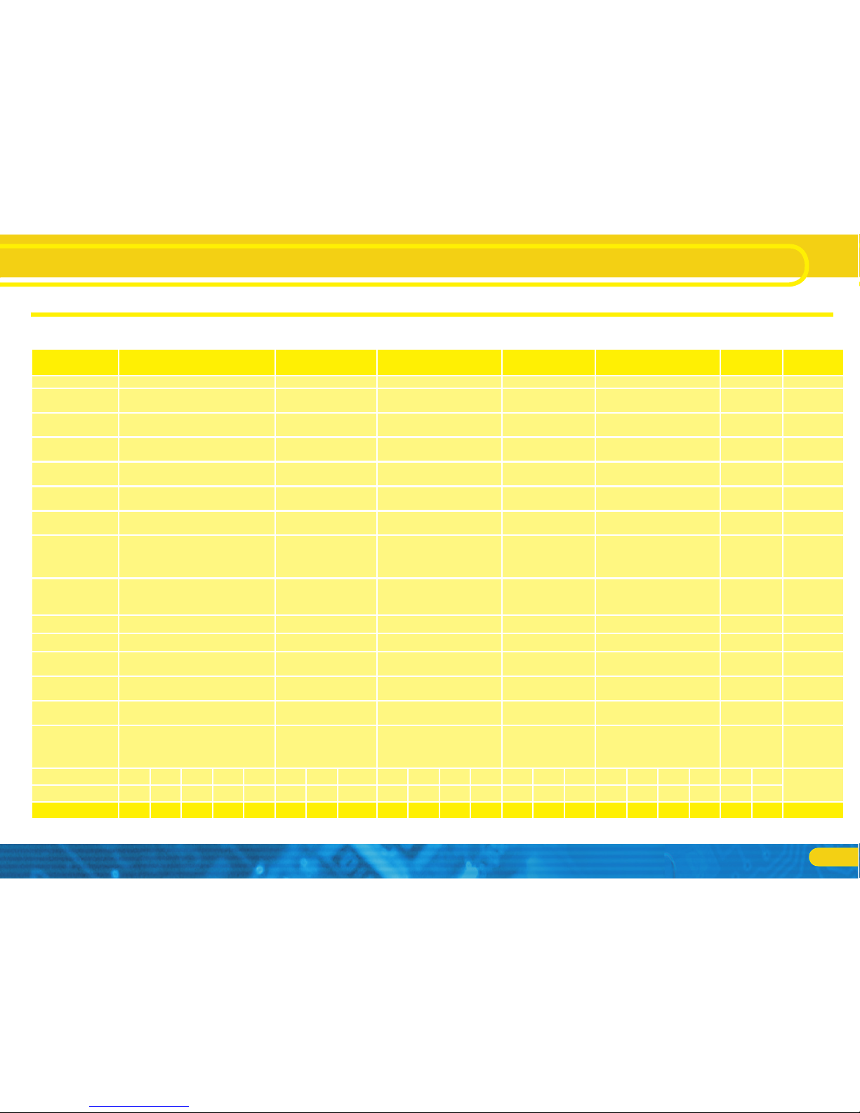
5.1. Overview of the LokPilot V4.0 decoders
LokPilot V4.0 LokPilot V4.0 DCC LokPilot
micro V4.0
LokPilot
micro V4.0 DCC
LokPilot V4.0 M4 LokPilot
Fx V4.0
LokPilot
XL V4.0
DCC operation
Ok Ok Ok Ok Ok Ok Ok
Motorola®
operation
Ok - Ok - Ok Ok Ok
M4 operation
(mfx® compatible)
- - - - Ok - Ok
Selectrix®
operation
Ok - Ok - Ok Ok Ok
Analogue DC
operation
Ok Ok Ok Ok Ok Ok Ok
Analogue AC
operation
Ok - - - Ok Ok Ok
DCC programming mode
Ok Ok Ok Ok Ok Ok Ok
Programming
with 6021,
Mobile/ Central
Station®
Ok - Ok - Ok Ok Ok
M4 programming
including automatic recognition
- - - - Ok - Ok
RailComPlus ®
Ok Ok Ok Ok Ok Ok Ok
ABC brake mode
Ok Ok Ok Ok Ok Ok Ok
Continuous motor current
1.1A 1.1A 0.75A 0.75A 1.1A - 4.0A
Function output
current
4/250 mA 4/250mA (PluX16:6) 2/150mA 2/150mA 4/250mA (PluX16:6) 6/250mA 8/250mA
Integrated
PowerPack
- - - - - - Ok
Optional
connection for
PowerPack buffer
capacitor
Ok Ok Ok Ok Ok - -
Connection type
NEM652 NEM651 21MTC PluX12 PluX16 NEM652 NEM651 21MTC NEM651 NEM651 NEM652 Next18 NEM651 NEM651 Next18 NEM652 21MTC PluX12 PluX16 NEM652 21MTC
Screw terminals
Wire W ire - Wire - Wire Wire - Direct Wire Wire - Direct Wire - W ire - Wire - Wire -
Article number 54610 54612 54614 54616 54617 54611 54613 54615 54688 54687 54683 54689 54685 54684 54686 64610 64614 64616 64617 54620 54621 54640
Introduction – The LokPilot Family

8
General Properties of all Decoders
5.2. Members of the LokPilot Family
All LokPilot V4.0 decoders have been completely redeveloped on
the basis of their predecessors´ excellent properties and they are
“better” in many respects.
All decoders of the LokPilot V4.0 family expand the capabilities
of their forerunners by further functions. These developments
further improve the driving characteristics, the operational reliability and the flexibility of the decoders. The LokPilot decoder is
the first choice for any sophisticated model train enthusiast that
places great value on excellent load control, outstanding driving
characteristics at low speed, and the utmost flexibility due to adaptation to specific requirements. LokPilot decoders automatically
detect the operating mode and are suitable for all commonly used
motors.
LokPilot decoders of the fourth generation offer you flexibility and
reliability that you would expect from a state-of-the-art decoder.
Future standards do not represent a problem either: due to the
flash technology, you can update the decoder at any time.
In order to suit the different scales and the related current draw of
the model locomotives, all LokPilot V4.0 decoders come in various
options that we now would like to introduce to you.
5.2.1. LokPilot V4.0
The LokPilot V4.0 is a multi-protocol decoder. It supports the Märklin® Motorola® format, the DCC-format and Selectrix®.
It can also work on analogue DC or AC layouts. Thus, it is ideally
suitable for mixed Motorola® / DCC environments.
Due to its manifold lighting functions and its adaptability to different applications, it is the perfect all-rounder for your H0 locomotives.
5.2.2. LokPilot V4.0 DCC
The LokPilot V4.0 DCC is a „thoroughbred” DCC decoder. Except
for the Motorola® and Selectrix® protocol, it supports all functions of the LokPilot V4.0. In analogue mode, it can only operate
on DC powered layouts.
The LokPilot V4.0 DCC is best suited for the DCC purist who does
not require multi-protocol operation and does not want to pay
for it either.
5.2.3. LokPilot micro V4.0
The LokPilot micro V4.0 is a real multi talent. Besides DCC and Motorola® and Selectrix® and a maximum current draw of 0.75A, it
is ideal for the small scales with little room for decoders.
5.2.4. LokPilot micro V4.0 DCC
The LokPilot micro V4.0 DCC “only” speaks DCC, however, it is
compatible with RailComPlus®. For the rest it equals the LokPilot
micro V4.0 decoder.
5.2.5. LokPilot XL V4.0
The LokPilot XL V4.0 is suitable for the larger gauges such as 0
gauge, G gauge and 1 gauge and has been optimised to operate
with models in these gauges. It supports four data protocols. Besides DCC with RailComPluS®, Motorola® and Selectrix® it also
supports the M4 data format and can automatically report to the
matching Märklin® central units. Due to its 8 function outputs as
well as 4 outputs for RC servos and a powerful motor end stage it
leaves nothing to be desired. Dirty track and their related problems
are a thing of the past due to the integral PowerPack.
5.2.6. LokPilot V4.0 M4
The LokPilot V4.0 M4 is ideal for everyone who does not want to
do without the automatic mfx® registration on a Märklin® central
station. Like the LokPilot V4.0 this decoder supports besides M4
the formats DCC with RailComPlus, Motorola® and Selectrix®
and can be operated on analogue layouts. The LokPilot V4.0 M4
fits into all popular H0 locomotives and can be programmed with
DCC command stations and also with Märklin® central units.

9
The LokPilot V4.0 supports and automatically detects the DCC
protocol with 14, 28, or 128 speed steps. Of course, operation
with the long 4-digit addresses is possible as well.
Contrary to the original Märklin®-decoders, LokPilot V4.0 decoders support up to 255 addresses and 28 speed steps in Motorola®
mode. With the appropriate command station such as the ESU
ECoS, you can expand the system limits of the Motorola® system
considerably.
Furthermore, all LokPilot V4.0 decoders support RailComPlus®. A
RailComPlus®-compatible command station immediately recognises a LokPilot V4.0 decoder fully automatically. The decoder will
transfer all of its important data to the command station. Finally,
you will never have to look for a loco address once again or carry
out any function mapping!
LokPilot XL V4.0 and LokPilot V4.0 M4 also support operation with
M4 and register automatically with Märklin® mfx® central units.
5.2.2. Motor Control
The most important function of digital decoders is motor control.
All LokPilot V4.0 decoders are designed for universal use and
therefore can control all commonly available DC motors, regardless if they are by ROCO®, Fleischmann®, Brawa®, Mehano®,
Bemo®, LGB®, Hübner®, Märklin® or others. Coreless motors
(such as Faulhaber® or Maxon®) also work fine with LokPilot.
You may continue to use any universal motors provided you replace the stator coils with a permanent magnet. You will find more
info on this topic in chapter 6.7.4.2.
Fifth-generation load compensation works with 20 resp. 40 kHz
and assures extremely silent operation, particularly with coreless
motors. Due to 10-bit technology, your locomotives will crawl at a
snail’s pace if so desired. Load compensation is easily adjustable to
various motor and gear combinations (compare with chapter 11).
With Dynamic Drive Control (DCC), you can limit the influence of
load control. Thus, you can control your locomotive in small throttle
notches for instance in the yard or on turnouts while the locomo-
General Properties of all Decoders
Both LokPilot V4.0 M4 and LokPilot V4.0 offer comprehensive
lighting effects, control of digital couplers as well as flexible function mapping.
5.2.7. LokPilot Fx V4.0
With the LokPilot Fx V4.0 you are able to digitalise motorless
vehicles. Therefore it has 6 function outputs. Therefore it has six
function outputs and can be operated with the Motorola® and
the DCC format. It also proves it´s worth on analogue DC and
AC layouts.
This LokPilot can be also used in combination with other LokPilot
or LokSound decoders.
5.2. General Properties of all Decoders
5.2.1. Operating Modes
All LokPilot V4.0 decoders (with the exception of the pure DCC
decoders) are true multi-protocol decoders with automatic detection of the operating mode „on-the-fly.“ The decoder analyses the
track signal and filters out the part that is reserved for it. Changing
from digital to analogue and back represents no problem whatsoever. This is important in case your e.g. fiddle yard still works in
analogue mode. Furthermore, all LokPilot decoders support the
relevant brake modes such as ROCO®, Lenz® or Märklin® and
stop as intended.
Especially the ABC brake sections are suitable for a simple stop
in front of the signal. LokPilot decoders achieve the maximum
compatibility with the operating system in order to enable you to
simulate even some unusual operational requirements.

10
General Properties of all Decoders
tive responds like the prototype at high speed on the main line
(for instance when climbing a gradient). In other words, if you do
not change the throttle setting then the locomotive will slow down
up the hill, as does the prototype. There is more info on this in
chapter 11.4.
The minimum and maximum speed of the LokPilot V4.0 is adjustable by setting two points which can be optionally adjusted by a
speed table with 28 entries.
Due to unique load compensation by ESU, there are no visible jerks
between speed steps – even in 14-speed-step-mode.
5.2.3. Analogue Mode
Quite a few LokPilot decoders replace analogue directional relays.
Therefore, you can not only set the starting speed and the maximum speed as well as pre-select which functions should be active
in analogue mode: even load compensation works in analogue
mode! This makes the LokPilot V4.0 work perfectly with analogue
locos: finally you are able to stop your older, too fast locos.
5.2.4. Functions
Standard features for LokPilot V4.0 decoders include the following
features: acceleration and brake times can be separately adjusted
and switched. The brightness of all function outputs can be separately set and allocated to the desired function buttons (function
mapping).
There is a wide range of options: dimmer, flickering firebox, gyrolight and mars-light, flash and double flash, blinker and alternate
blinker as well as switch functions with timers (e.g.: for Telex) and
a special coupler function for remote controlled couplers by Krois® and ROCO® including the automatic pushing and pulling.
Furthermore LokPilot XL decoders can also control up to 4 RC
servos directly.
The unique and once more improved ESU function mapping enables you to allocate every function to the function buttons F0 to
F15; even multiple allocations are possible. You will find more info
on this in chapter 12.
5.2.5. Programming
Where intended, LokPilot decoders support all programming
modes including POM (Programming-On-the-Main). You can use
any NMRA-DCC compatible command station for this purpose.
Even with the Märklin® central units 6020®, 6021®, Mobile Station® and Central Station® all settings are adjusted electronically.
Most LokPilot V4.0 decoders support a simple-to-use programming procedure.
Owners of the ESU ECoS enjoy an even more comfortable method
of programming: you can read all possible settings in plain text on
the large display and easily adjust them – even during operation!
LokPilot V4.0 M4 and LokPilot XL V4.0 will be automatically detected and read by all Märklin® mfx® central units and can be
graphically programmed with them.
5.2.6. Operational Reliability
LokPilot decoders store the current operating status. Thanks to this
data storage, the decoder will start again as quickly as possible
after a service interruption. The LokPilot XL´s built-in PowerPack,
which also can be optionally installed into some decoders, assures
continuous power even in case of poor electrical contact or critically laid tracks.
5.2.7. Protection
All function outputs as well as the motor output have protection
against overload and short circuit. We want you to enjoy your LokPilot decoders for a long time.
5.2.8. Future built-in
All LokPilot V4.0 decoders are suitable for firmware updates due
to the flash memory. You may add new software functions at a
later stage.
11
Installing the Decoder
6. Installing the Decoder
6.1. Requirements for Installation
The locomotive must be in perfect operating condition prior to the
conversion: Only a locomotive with faultless mechanical properties
and smooth running characteristics in analogue mode is worth
converting to digital. Check and replace all wear and tear parts
such as motor brushes, wheel contacts, light bulbs etc., if necessary.
Please take note of the remarks in chapter 3 in order to prevent
possible damage of the decoder during installation!
6.2. Installing the Decoder
The components on the decoder must under no circumstances
touch any metal parts of the locomotive since this could lead to
short circuits and damage or even destruction of the decoder.
Therefore, all LokPilot decoders (with the exception of the ones with
the 21MTC or PluX interface) come with a protective shrink sleeve.
Never wrap the decoder in insulating tape. If there is no ventilation
around the decoder, it may lead to a heat build-up and ultimately
to the destruction of the decoder. Rather apply the insulating tape
to the metal parts of the locomotive.
Mount the decoder at a suitable location. In most model locomotives,
there is a dedicated space for the decoder. To hold the decoder in
place use double sided adhesive tape or some (just a little) hot glue.
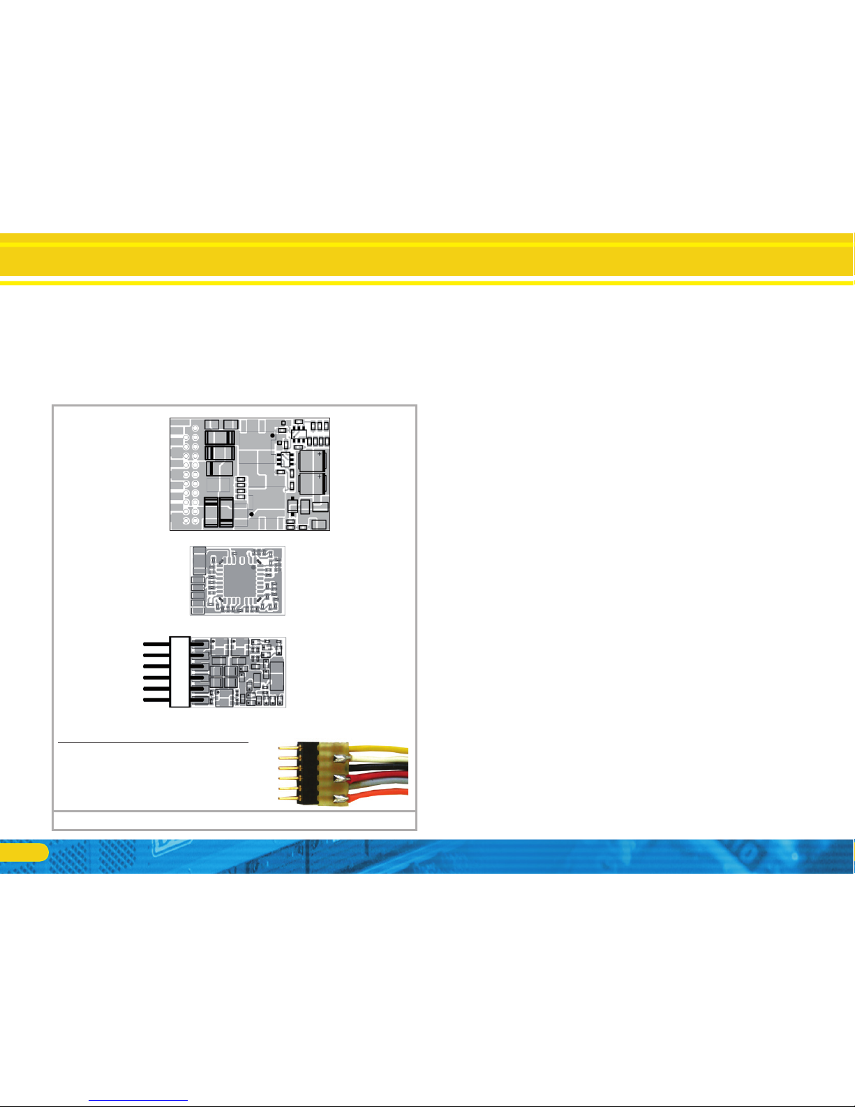
6.3. Locomotives with 8-pin NEM 652 interface
Some LokPilot V4.0 decoders are supplied with an 8-pin interface
as per NEM 652 (refer to Fig 1). Installation in locomotives with
this interface is particularly easy:
Remove the locomotive body. Please observe the instructions in •
the manual of your locomotive!
Remove the dummy plug from the socket and keep it in a suitable •
place for later use.
LokPilots with NEM652 interfaceFigure 1:
AUX2 --
Right motor terminal --
Right track connection --
Rear light --
Common (+ pole) --
AUX1 --
Head light --
Left track connection --
Left motor terminal --
54610 LokPilot V4.0
54611 LokPilot V4.0 DCC
64610 LokPilot V4.0 M4
Pin Description Colour
1 Right motor terminal orange
2 Rear light yellow
3 Output AUX1 green
4 Left track connection black
5 Left motor terminal grey
6 Head light white
7 Common (+ pole) blue
8 Right track connection red
5 4
1
Insert the plug of the decoder in such a way that pin 1 of the •
plug (this is the side with the red / orange wires) sits next to the
cornerofthesocketthatisusuallymarkedwith*,+,•or1.Please
make sure that the pins are straight and do not tilt when inserting the plug.
Do not rely on the assumption that the wires of the harness have
to face in a certain direction: the only reliable reference is the
marking of pin 1.
54620 LokPilot Fx V4.0
AUX2 -AUX3 --
Right motor terminal --
Rear light --
Common (+ pole) --
AUX1 --
Head light --
Left track connection --
AUX4 --
12
Installing the Decoder
6.4. Locomotives with 6-pin NEM 651 interface
Some LokPilot V4.0 decoders have a 6-pin NEM 651 plug (as per
Figure 2). Installation in locomotives with this interface is particularly easy:
Remove the locomotive body.•
Remove the dummy plug from the socket and keep it for later use.•
Insert the plug of the decoder in such a way that pin 1 of the plug •
(this is the side with the red / orange wires) sits next to the corner
ofthesocketthatisusuallymarkedwith*,+,•or1.Pleasemake
sure that the pins are straight when inserting the plug.
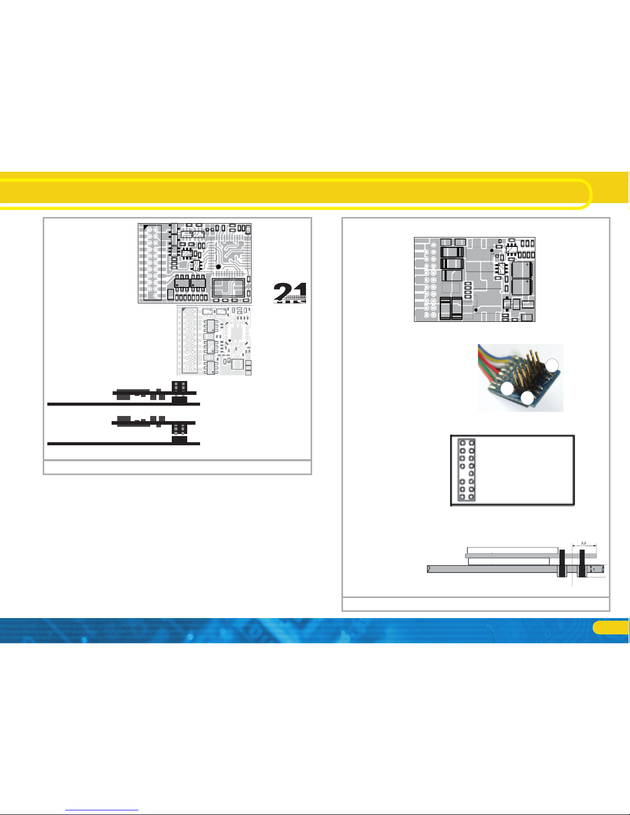
6.5. Locomotives with 21MTC interface
Some LokPilot decoders are available with a variant of the 21MTC
interface as per Fig. 3. Installation in locomotives with this interface is particularly easy since the plug-socket connector facilitates
the mechanical fixing as well.
Remove the locomotive body. Please observe the instructions in •
the manual of your locomotive!
Remove the dummy plug from the socket and keep it in a suitable •
place for later use
Search for the missing pin in the plug on the circuit board of the •
locomotive. The missing pin serves as the marker. Memorise its
location.
You can insert the decoder in two ways: either the pins are put •
through the decoder; the socket of the decoder remains visible after installation (mounting on top) or the decoder is inserted in such
a way that the pins go straight into the socket. Once the decoder
sits in the socket, the socket is hidden from view. This method is
common for Brawa® locomotives.
Which of the two mounting positions is the correct one depends •
solely on the locomotive. The position of the marker-pin is the
crucial indicator.
Plug the decoder into the socket in such a way that the locomotive •
interface corresponds with the decoder.
Do not apply too much pressure when inserting the plug. The de-•
coder must go in without force.
Check if the decoder sits correctly.•
LokPilots with NEM651 interfaceFigure 2:
Solder connect. (violet) AUX2 --
Right motor terminal --
Right track connection --
Rear light --
(blue) Common (+ pole) --
Solder connect. (green) AUX1 --
Head light --
Left track connection --
Left motor terminal --
54612 LokPilot V4.0
54613 LokPilot V4.0
DCC
64613 LokPilot V4.0
M4
Pin Description Colour
1 Right motor terminal orange
2 Left motor terminal grey
3 Right track connection red
4 Left track connection black
5 Head light white
6 Rear light yellow
54687 LokPilot micro V4.0
54684 LokPilot micro V4.0 DCC
54688 LokPilot micro V4.0
54685 LokPilot micro V4.0 DCC
Right motor terminal
Left motor terminal
Right track connection
Left track connection
Head light
Rear light
Decoder back view
LokPilot micro V4.0
LokPilot micro V4.0 DCC
(blue) Common (+ pole) --
--
GND -Solder. connect. AUX2 (Logic level) -Solder. connect. AUX1 (Logic level) --
13
n.c. 1
n.c. 2
n.c. 3
AUX4 4
n.c. 5
n.c. 6
Rear light 7
Head light 8
n.c. 9
n.c. 10
Index pin 11
54614 LokPilot V4.0
54615 LokPilot V4.0
DCC
64614 LokPilot V4.0
M4
LokPilots with 21MTC interfaceFigure 3:
22 Right track
21 Left track
20 GND
19 Motor right
18 Motor left
17 n.c.
16 Common (+)
15 AUX1
14 AUX2
13 AUX3
12 VCC
How to connect the decoder:
Insert the decoder with connector
towards top
(e.g. Liliput®, ESU, HAG®,
Märklin®)
Insert the decoder with connector
towards bottom
(e.g. Brawa®)
Locomotive PCB
(Side view)
Locomotive PCB
(Side view)
54621 LokPilot Fx
V4.0
Installing the Decoder
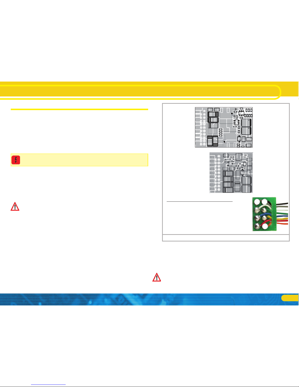
6.5.1. Connecting C-Sine motors („SoftDrive-Sinus“)
The LokPilot decoder cannot drive the newer Märklin® models
with C-Sine motors (also called „SoftDrive-Sinus“) directly. To facilitate this, a circuit board supplied ex works with the locomotive is
required. This circuit board will be controlled by a LokPilot decoder.
Märklin® uses the 21MTC interface installed on this circuit board
and thus utilises the normal motor commands from the decoder or
a SUSU interface for the exchange of information.
The LokPilot V4.0 with the 21MTC interface is suitable for controlling the C-Sine control electronics provided some parameters are
set accordingly. Chapter 11.5. explains the necessary steps.
Head light 7
Common (+ pole) 9
Index pin 11
Rear light 13
8 Motor +
10 Motor 12 Right track
14 Left track
16 AUX1
18 AUX2
17
7
18
PluX12
AUX2 --
Right motor terminal --
Right track connection --
Rear light --
(blue) Common (+ pole) --
AUX1 --
Head light --
Left track connection --
Left motor terminal --
54616 LokPilot V4.0
64646 LokPilot V4.0 M4
PluX16
LokPilots with PluX interfaceFigure 4:
- 1
ZBCLK 3
GND 5
Head light 7
U+ 9
Index pin 11
Rear light 13
- 15
- 17
(AUX4) 19
- 21
56417 LokPilot V4.0
64617 LokPilot V4.0 M4
2 (AUX3)
4 ZBDTA
6 8 Motor +
10 Motor 12 Right track
14 Left track
16 AUX1
18 AUX2
20 22 -
14
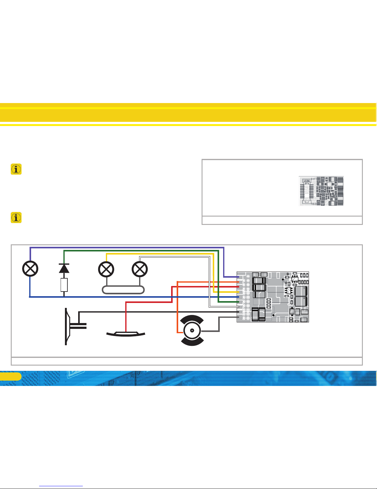
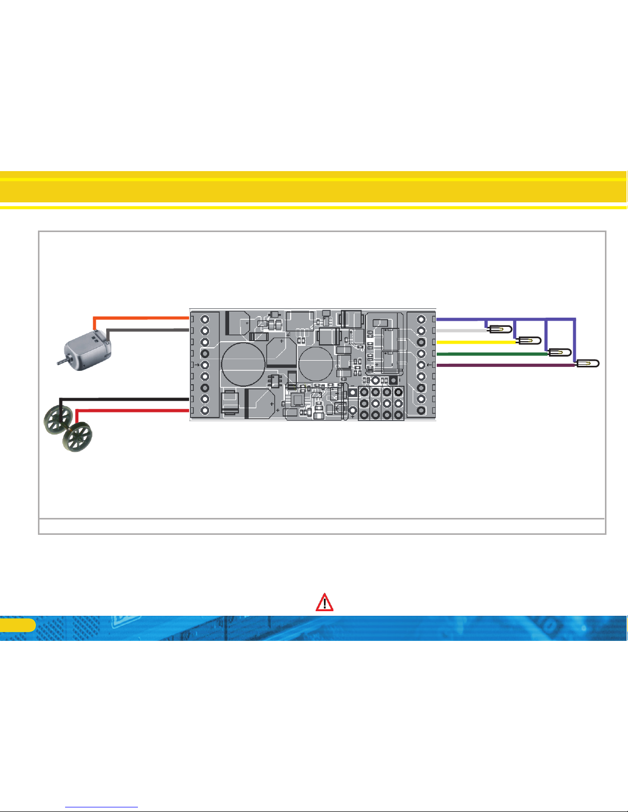
Installing the Decoder
Wiring diagram for LokPilot V4.0, LokPilot V4.0 DCC (wiring example)Figure 5:
54610 LokPilot V4.0
54611 LokPilot V4.0 DCC
64610 LokPIlot V4.0 M4
violet
orange
red
yelllow
blue
green
white
black
grey
R
Loco housing
violet
AUX2
green
AUX1
yellow
Rear
Light
white
Head
Light
black
red
orange grey
Right track 1
Motor + 2
AUX1 3
AUX3 / Trainbus Clk 4
GND 5
(Blue) Common (+) 6
- 7
Head light 8
Left track 9
18 Right track
17 Rear light
16 15 (Blue) Common (+)
14 GND
13 AUX4/Trainbus DTA
12 AUX2
11 Motor -
10 Left track
1
9
18
10
Decoder back view
54689 LokPilot micro V4.0 Next18
LokPilots with Next18 interfaceFigure 6:
6.8.1. Wiring Diagram for LokPilot
6.6. Loks mit PluX-Schnittstelle
Some LokPilot decoders are supplied with a PluX12 plug. These
decoders can also be installed in locomotives with a PluX22 interface. One position on the multi-pin plug of the decoder has no pin
(index pin). This position should be marked in the locomotive.
Please consider the correct seating of the decoder on the PluX
socket!
6.8. Locomotives without interface
All LokPilot decoders have an interface (plug). There is no „wiresonly“ version. Please remove the plug at the end of the harness
should this become necessary.
Please do not extend any wires at the decoder end. If necessary
use an extension harness (also refer to chapter 17).
6.7. Locomotives with Next18 interface
Some LokPilot micro decoders are shipped with an 18-pin Next18
interface. More information about how to install the decoder is
given in chapter 6.5.
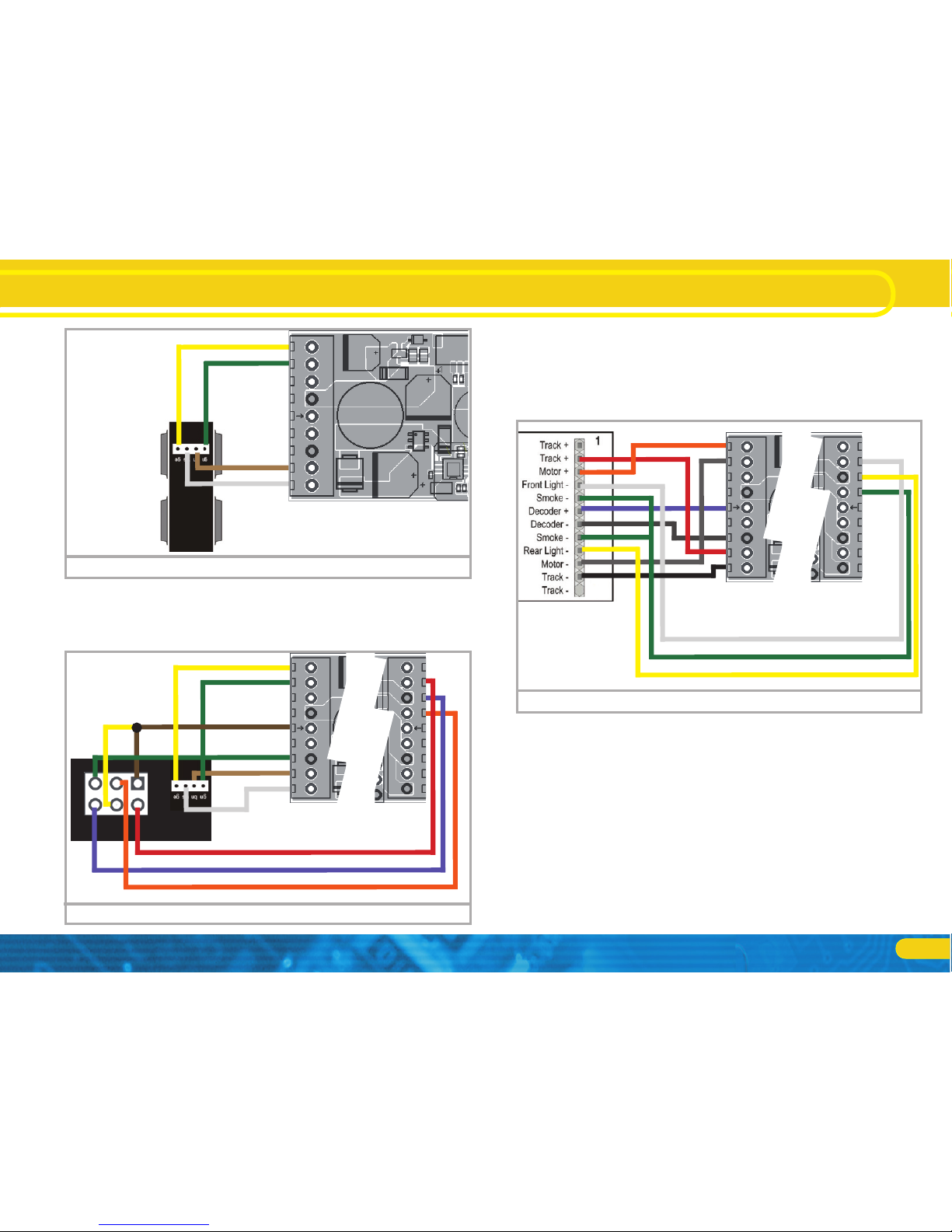
15
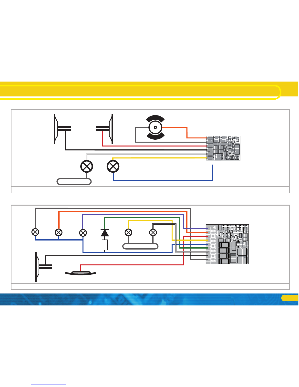
Wiring Diagram for LokPilot
Wiring diagram for LokPilot micro V4.0, LokPilot micro V4.0 DCC (wiring example)Figure 7:
54683 LokPilot micro V4.0
54687 LokPilot micro V4.0
54684 LokPilot micro V4.0
DCC
orange
grey
red
black
white
yellow
blue (optional, instead of housing GDN)
Motor
yellow
Rear
Light
white
Head
Light
Loco housing
black
red
orange
grey
For decoder back see figure 2).
Wiring diagram for LokPilot Fx V4.0 (wiring example)Figure 8:
54620 LokPilot Fx V4.0
violet
orange
red
yellow
blue
green
white
black
grey
R
Loco housing
black red
grey
AUX4
orange
AUX3
violet
AUX2
green
AUX1
yellow
Rear
Light
white
Head
Light
6.8.2. Wiring Diagram for LokPilot micro
6.8.3. Wiring Diagram for LokPilot Fx
16
Wiring diagram for LokPilot XL
6.8.4.1. Wiring to LGB® gear boxes
The decoder can wired directly to suitable LGB® locomotives with
the LGB® interface cable. Motor, light and auxiliary functions can
be controlled. The cable with the part number 55026 is available
from LGB®. Remove the dummy plug from the interface cable
6.8.4. Wiring diagram for LokPilot XL decoders
DC Motor
Motor -
Motor +
Left track
Right track
U+
GND
Wheel sensor
Trainbus (Susi)
Rear light
Head light
AUX1
AUX2
AUX3
AUX4
AUX5
AUX6
U+
GND
+5V
IMP
Servo4 (AUX10)
Wiring diagram for LokPilot XL V4.0 (wiring example)Figure 9:
and screw the ends into the terminals of the decoder after having
removed the insulation at the ends of the wires. Set the DIP switch
at the interface according to the instructions from LGB®.
Non-compliance may lead to the destruction of the decoder!
UVAR
+5V
GND
+5V
IMP
Servo3 (AUX9)
Servo2 (AUX8)
Servo1 (AUX7)
17
Installing the Decoder
1
2
5
6
brown/
yellow=U+
red=Head light
blue=Rear light
green=GND
orange=AUX1
LGB® interfaceFigure 11:
Aristocraft® interfaceFigure 12:
6.8.4.3. Wiring to the Aristocraft® interface
Many Aristocraft locomotives have a digital interface which represents a manufacturer´s standard only. They are ready for the installation of digital components.
The wiring is shown in figure 12:
LGB® gear boxFigure 10:
brown=
Left track
white=
Right track
yellow=Motor +
green=
Motor -
6.8.4.2. Wiring to an LGB® interface
More modern LGB® locomotives have a digital interface and thus
are ready for installing digital components.
18
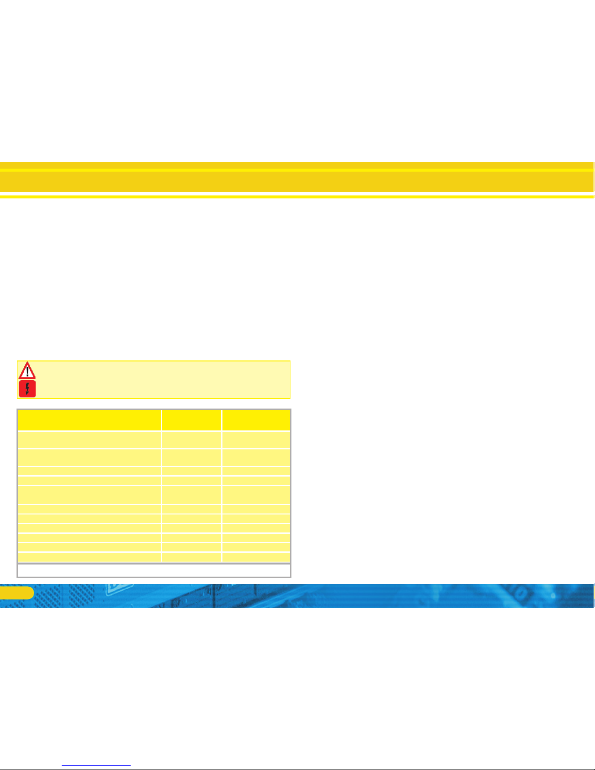
6.8.5. Colour Coding by Märklin®
Märklin® uses a different colour coding system compared to the
DCC colours. Please refer to figure 13 for more information.
6.8.6. Motor and track connections
Firstly, please cut all wires installed in the locomotive. Take special
care to remove any connections to the chassis (ground): the motor
leads must be positively potential-free, in other words they may
not have any contact to the chassis or body or the wheels and
wheel contacts.
It is particularly easy to overlook such connections in Fleischmann®
locomotives.
Make notes of which motor lead connects the motor with the
right and the left wheel contact.This avoids mistakes and assures
that your locomotive runs in the right direction.
Please check all connections with an Ohmmeter. Search for
short circuits, particularly between the motor leads and the
wheel contacts.
Connect the red wire to the right rail pickup or the centre pick •
up in AC models.
Connect the black wire to the left rail pickup or the chassis in •
AC models.
Connect the orange wire with the motor terminal, which originally •
lead to the right wheel pick up (centre pick up in AC models).
The grey wire goes to the terminal, which originally connected to •
the left rail (chassis for AC models).
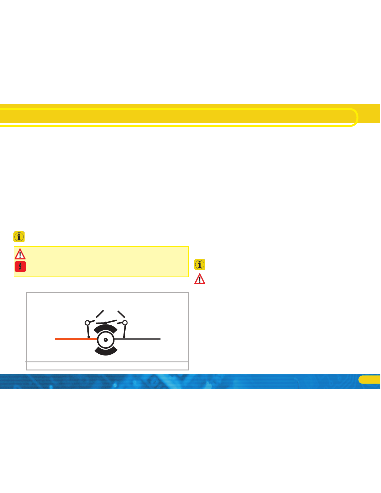
6.8.6.1. Connecting DC and Coreless Motors
You may use all DC motors commonly used for model trains provided they do not exceed the current limit of the decoder.
In some cases with the 5-pole High Performance Drive by Märklin®, you may find three anti-interference capacitors.
The two capacitors connected directly to the motor leads and the
motor housing MUST be removed (also refer to Fig. 14).
Installing the Decoder
Description Märklin® colour
ESU colour (NMRA
DCC Norm)
AC: Power pick up show (Center rail)
DC: Right track connection
red red
AC: Outside rails
DC: Left track connection
brown black
eft motor terminal blue orange
Right motor terminal green grey
Common (rectified track voltage) (+Pole) for
function outputs
orange blue
Function output Rearlight yellow yellow
Function output Headlight grey white
Function output AUX1 brown/red green
Function output AUX2 brown/green violet
Function output AUX3 brown/yellow Function output AUX4 brown/white -
Colour coding by Märklin® in contrast to the DCC wiring codeFigure 13:
19
6.8.6.2. Connecting Universal Motors with HAMO-Conversions
Do not wire universal motors installed in many older Märklin®
locomotives (also known as AC motors) directly to LokPilot decoders. You must modify the motor by first installing permanent
magnets – so called HAMO magnets.
You may purchase these magnets from your ESU dealer.
We supply three types of magnets. Please refer to chapter 18.2.
for more information regarding motor conversions with permanent magnets.
6.9. Connecting Additional Functions
You can wire any kind of load such as light bulbs, LEDs (light emitting diodes), smoke generators or similar devices to the function
outputs provided the maximum current draw is less than that of
the decoder output.
The permitted maximum current draw per function output is listed
in chapter 20 under „Technical Data.“
Please make sure that the load does not exceed the permitted
maximum current and there are no short circuits. The outputs of
the LokPilot have protection but if an external voltage is applied,
the outputs may suffer damage or destruction.
6.9.1. Overload Protection of Function Outputs (Blinking)
The function outputs of LokPilot decoders have electronic protection against overload and short circuit. The decoder keeps
checking the sum of all function output currents. If the current
is too high, the decoder will switch off the outputs. After about
1 second, the decoder tries to switch them on again. Should the
current still be too high – perhaps due to a short circuit – the same
procedure starts again.
When using light bulbs (incandescent lamps) please note the following: they draw a very high „inrush current“ when they are
switched on, that becomes lower after a few moments. Therefore,
it can happen with 12V bulbs that the headlights „flash“ briefly
during switch-on and then extinguish due to the overload protection of the decoder. The lights will be shortly switch on and off
again in a one-second cycle. This results from a much too high
inrush current of the bulbs; the decoder is not able to distinguish
between the bulbs´ high inrush current and an overload. Therefore
it is important to install the correct bulbs.
6.9.1.1. Suitable light bulbs
Only install bulbs rated 16V or higher and with a nominal current
draw, that does not exceed 50 mA.
Many older models by ROCO® and Fleischmann® have 12V bulbs
installed. They draw a high current, become very hot, and may
cause damage to the locomotive. Replace them with 16V bulbs.
6.9.1.2. Micro incandescent lamps wired to LokPilot XL V4.0
The LokPilot XL V4.0 decoder is suitable for direct connection of
micro incandescent lamps. The decoder has an integral voltage
regulator for this purpose. The default setting is 1.8V designed for
long life of 3V lamps. Do not connect the return wire of the lamp
to U+ but rather to the terminal marked “UVAR”.
Installing the Decoder
Remove capacitors!
5-pole Märklin® motorFigure 14:
orange grey
20
Installing the Decoder
You may change the voltage setting by exchanging a resistor. An
SMD resistor is required. Type 0805, power rating 0.125W:
R124
R125
Rear light
Head light
UVAR (1,5-3V)
Voltage R124
1.5V 33 kOhms
2.5V unsolder
3.0V 48 kOhms, unsolder R125
The maximum load of the UVAR output is 500mA.
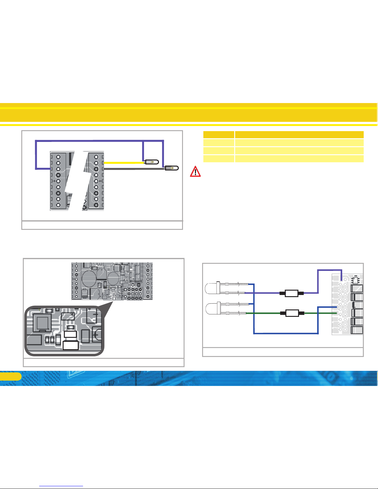
6.9.2. Using LEDs
If you like to use LEDs, then a resistor must be wired in series with
the LEDs. It should have a rating between 470 Ohms and 2.2 kOhms. Running the LEDs without this resistor will lead to their immediate destruction! Unlike lightbulbs, LEDs are polarity-sensitive.
The minus (cathode) end of the LED is connected to the function
output, the plus (anode) end is connected to the blue (function
common) wire.
Please to not forget to switch the respective function output to
LED mode. This will ensure a prototypical presentation of all light
effects. Please refer to chapter 12.3. for more details.
Micro incandescent lamps wired to XLFigure 15:
Resistor for UVAR on XL decoderFigure 16:
violet
green
AUX2
AUX1
R
470 Ohms
resistance
+
+
blue ( common function )
470 Ohms
resistance
R
Wiring LED to output AUX1, AUX2Figure 17:
21
6.9.3. Connecting the Light Outputs, AUX1 and AUX2
This procedure depends on the wiring of the lights and auxiliary
functions in the locomotive:
a) The lamps / function outputs are insulated from the common
pole (ground) (i.e.: the locomotive chassis); therefore they are
potential free. Fig. 17 shows the correct wiring for the outputs AUX1 and AUX2. The functions of the locomotive must
be potential-free, in other words there may not be any other
connection to the function besides the wires from the decoder.
The voltage at these outputs is about 1.5V lower than the track
voltage. The blue wire is the „plus-pole“; the function output
the „minus-pole”.
If LEDs are installed (also refer to Fig. 17), then a resistor must be
wired in series with the LEDs. It should have a rating of between
470 Ohms and 2.2 kOhms. Running the LEDs without this resistor
will lead to their destruction!
b) The lamps / function outputs are wired (together) against the
chassis of the locomotive (as in most locomotives by Märklin®
as well as in most older locomotives by Fleischmann® and
ROCO®).
The wiring is simpler but the available voltage is about half. This
type of connection is not suitable for multi-protocol operation.
Both M4 and Motorola® packets are asymmetrical. Therefore, the
function outputs do not have continuous power. This leads to a
rhythmic flicker of the headlights (pulsing) that becomes particularly obvious with LEDs.
Furthermore, the headlights will only work in one direction in
analogue DC mode. Whether it will be the forward lights or the
backup lights depends on which way you have placed your locomotive on the track.
Solder the backup lights to the yellow wire, the headlights to the •
white one.
If your locomotive is wired according to option b), then it is ready
for use. Otherwise, you must connect the remaining wires of all
bulbs and functions together to the blue wire. This pole may not
have any connection to the chassis!
It is possible to use both options in the same locomotive as shown
in Fig. 17.
6.9.4. Using AUX3 and AUX4
6.9.4.1. LokPilot with 21MTC interface
LokPilot decoders with 21MTC interface have two additional outputs besides the 4 standard outputs, namely AUX3 and AUX4.
Since they are pure „logic-outputs“, it is not possible to connect
any external loads directly. External power transistors are required.
Connect AUX3 and AUX4 via the 21MTC interface; there are
equal to the other outputs. ESU offers an appropriate adapater
board (art.no. 51968) with transistors.
6.9.4.2. LokPilot with PluX16 interface
LokPilot decoders with PluX16 interface have all in all 6 power
outputs. Consumers can be directly connected.
6.9.4.3. LokPilot Fx V4.0
The LokPilot Fx V4.0 offers up to 6 function outputs (also refer to
Fig. 7). You can access the outputs AUX3 and AUX4 via the orange
resp. the grey wire.
The 21MTC interface version allows to switch output AUX3 and
AUX4 as either logical output or amplified output. This makes a
maximum compatibility between NEM660 and the available rolling material possible.
6.9.5. AUX5 to AUX 6
LokPilot XL V4.0 decoders decoders have additional function outputs that may be used as desired.
Installing the Decoder
22
Seuthe smoke generators have considerable production tolerances. Therefore, it is possible that one unit works perfectly
well while another does not. Type of distillate and filling level
have an influence as well.
c) Setting the decoder output
For correct smoking action you should set the AUX output to
„Dimmer“ as well as full „Brightness.“ More info in chapter
12.
d) Connecting the smoke generator
Most smoke generators are wired against the chassis (ground).
Therefore the smoke generator only receives current in every
second half cycle. How much power gets to the smoke generator depends on your command station and the digital protocol.
Generally, Seuthe type 11 is recommended, but it does not get
enough power and therefore does not smoke satisfactorily.
There are two options on how to solve this problem:
Solution 1: Using the Seuthe No. 10. This type is intended for analogue operation and draws a relatively high current. Subject to its
tolerance levels, it may trigger the overload protection of the decoder. In this case, you must wire a relay (ESU No. 51963) into the
circuit or you slightly reduce the „Brightness“ of the output.
Solution 2: Using the Seuthe No. 11. Do not wire it against the
chassis (ground) but rather use the blue wire for the second pole
(„U+“). This prevents the asymmetric track signal from interfering
with the smoke generator. It represents the best solution but is
sometimes a bit difficult in terms of wiring.
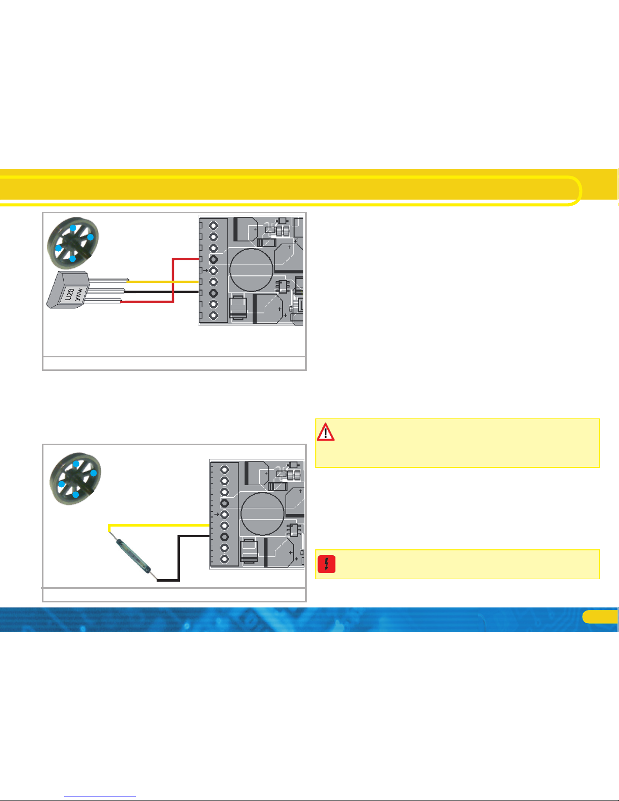
6.9.7.1. HALL Sensor IC
A Hall sensor is an electronic circuit that responds to an alternating
magnetic field similar to a reed switch. Hall sensors are easier to
adjust since the distance between sensor and magnet is not critical. A commonly used hall sensor, that can be purchased via mail
order is the TLE4905 by Siemens / Infineon. There are also many
compatible devices on the market. The terminals have to be wired
to the LokPilot as shown in figure 19.
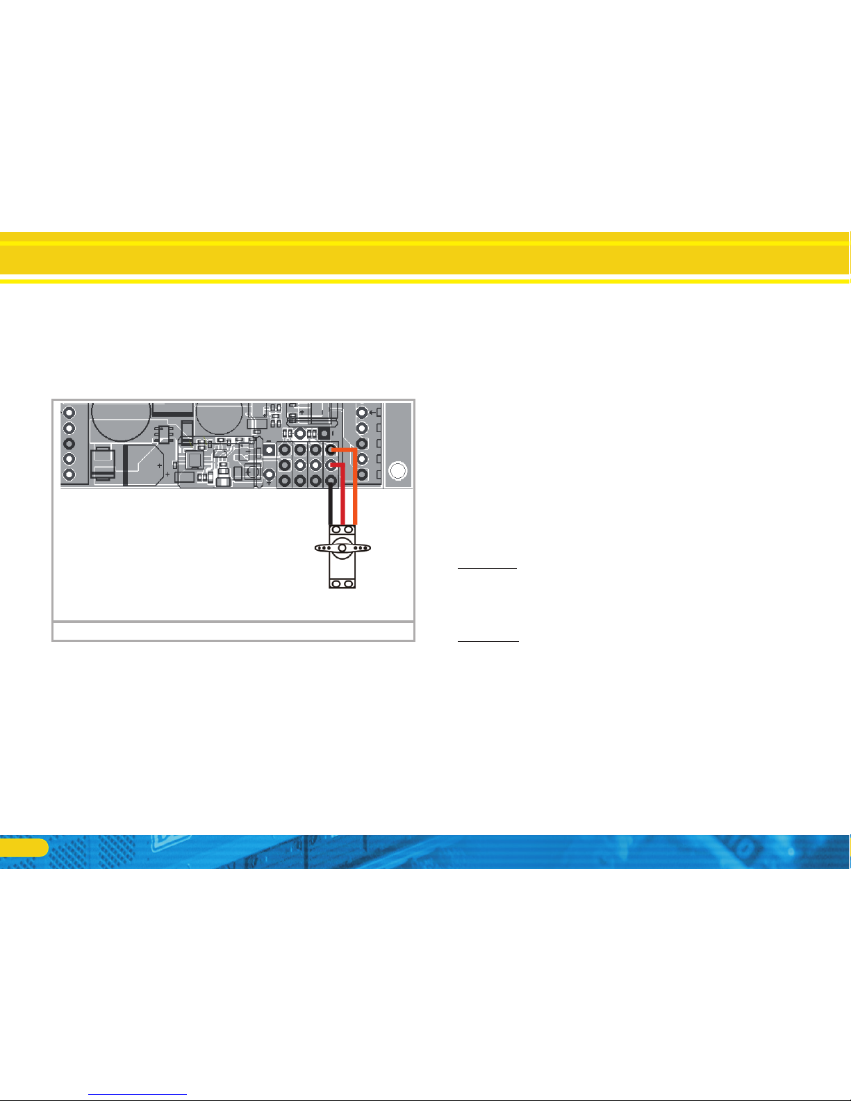
6.9.5.1. Servo outputs
AUX7 through to AUX10 may be used for “normal” loads but
are also capable to drive RC servos. All commercially available RC
servos with a positive pulse are suitable. Please observe the correct polarity when connecting the servos. Prior to controlling the
servos you must set the outputs to “Servo”. Please refer to chapter
12.3.7. for more information.
6.9.6. Suitable Smoke Generators
Unfortunately, it is not an easy task to find the right smoke generator for each locomotive. The amount of smoke generated depends
on the following factors:
a) Track voltage
The track voltage varies depending on the command station.
Therefore, it is possible that a locomotive generates smoke
when driven by one digital system but does not generate any
smoke with another system. Even 1V variation makes a big
difference.
b) Type and tolerance of the Seuthe smoke generator and the
smoke distillate
Installing the Decoder
Servo1
(AUX7)
GND
+5V
IMP
RC servos to LokPilot XL V4.0Figure 18:
23
Installing the Decoder
Place four miniature magnets on the inner side of the driving
wheel in such a way that the magnet will trigger the HALL IC each
time it will pass the sensor IC. For 3-cylinder locomotives, you may
even need 6 magnets, depending on the cylinder configuration.
6.9.7.2. Reed switch sensor
If you have trouble obtaining a hall sensor IC, you may also use a
subminiature reed switch. They are connected to the decoder with
two pins only. However, their sensitivity is not as good as hall IC
sensors and stronger magnets may be needed in order to trigger
these reed switches correctly. Furthermore the position of the reed
switches needs to be considered.
6.10. Connecting Capacitors
On many older layouts, current pick up of locomotives is not very
reliable. Therefore, power interruptions may cause a stop or jerky
movement when the locomotive travels over turnouts at low
speeds. This can be overcome with buffer capacitors (100 mF /
25V or higher show the desired results). If desired you may connect them to the LokPilot V4.0 or LokPilot micro V4.0.
Soldering wires onto a decoder requires quality soldering equipment and experience. Our warranty does not cover damage
caused by inappropriate soldering. Consider carefully if you really need that capacitor.
6.10.1. LokPilot H0, LokPilot micro decoders
You can connect two larger capacitors as per the circuit in the
upper half of figure 21.
The capacitor is charged via a resistor (100 Ohms) thus preventing
the digital system from interpreting the charging current as short
circuit at the time of switch-on. The diode makes sure that the
energy of the capacitor is fully available when required.
However, you may not run the LokPilot decoder on AC layouts
anymore. Risk of destruction!
Input
GND
VCC
Hall Sensor IC
4x
Mini
magnet
HALL IC wiring to a LokPilot XLFigure 19:
Input
GND
Reed switch
4x
Mini
magnet
Reed switch wiring to a LokPilot XLFigure 20:
 Loading...