

Esu LokPilot V3.0, LokPilot V3.0 DCC, LokPilot V3.0 M4, LokPilot XL V3.0, LokPilot micro V3.0 User Manual
...
1
User manual
7. edition, November 2009
LokPilot V3.0
LokPilot V3.0 DCC
LokPilot V3.0 M4
LokPilot XL V3.0
LokPilot micro V3.0
LokPilot micro V3.0 DCC
LokPilot Fx V3.0
LokPilot Fx micro V3.0
LokPilot V3.0
P/N 51978

2
Contents
1.Declaration of conformity1.Declaration of conformity
1.Declaration of conformity1.Declaration of conformity
1.Declaration of conformity
......................................................................................
......................................................................................
...........................................
44
44
4
2. WEEE-Declaration (Eur2. WEEE-Declaration (Eur
2. WEEE-Declaration (Eur2. WEEE-Declaration (Eur
2. WEEE-Declaration (Eur
ope only)ope only)
ope only)ope only)
ope only)
..................................................................
..................................................................
.................................
44
44
4
3. Important Notes – Please r3. Important Notes – Please r
3. Important Notes – Please r3. Important Notes – Please r
3. Important Notes – Please r
ead this chapter firstead this chapter first
ead this chapter firstead this chapter first
ead this chapter first
....................
....................
..........
55
55
5
4. How this manual helps you4. How this manual helps you
4. How this manual helps you4. How this manual helps you
4. How this manual helps you
................................................................................
................................................................................
........................................
66
66
6
5. Intr5. Intr
5. Intr5. Intr
5. Intr
oduction – The LokPilot Familyoduction – The LokPilot Family
oduction – The LokPilot Familyoduction – The LokPilot Family
oduction – The LokPilot Family
..........................................................
..........................................................
.............................
66
66
6
5.1. The Members of the LokPilot Family ............................ 6
5.1.1. LokPilot V3.0 Decoders – an Overview ...................... 7
5.1.2. LokPilot V3.0 ............................................................. 7
5.1.3. LokPilot V3.0 DCC .................................................... 8
5.1.4. LokPilot V3.0 M4 ...................................................... 8
5.1.5. LokPilot XL V3.0
........................................................ 8
5.1.6. LokPilot micro V3.0 ................................................... 8
5.1.7. LokPilot micro V3.0 DCC .......................................... 8
5.1.8. LokPilot Fx V3.0 ........................................................ 8
5.1.9. LokPilot Fx micro V3.0 ............................................... 8
5.2. General Properties of all Decoders ............................... 8
5.2.1. Operating Modes ...................................................... 8
5.2.2. Motor Control ........................................................... 8
5.2.3. Analogue Mode ........................................................ 9
5.2.4. Functions .................................................................. 9
5.2.5. Programming ............................................................ 9
5.2.6. Operational Reliability ............................................... 9
5.2.7. Protection .................................................................. 9
5.2.8. Future included ......................................................... 9
6. Installing the Decoder6. Installing the Decoder
6. Installing the Decoder6. Installing the Decoder
6. Installing the Decoder
............................................................................................
............................................................................................
..............................................
1010
1010
10
6.1. Requirements for Installation ..................................... 10
6.2. Installing the Decoder ................................................ 10
6.3. Locomotives with 8-pole NEM 652-Interface .............. 10
6.4. Locomotives with 6-pole NEM 651-Interface ............. 11
6.5. Locomotives with 21MTC Interface ............................ 12
6.5.1. Connecting C-Sine motors („SoftDrive-Sinus“) ....... 12
6.6. Locomotives without Interface ................................... 12
6.6.1. Wiring Diagram for LokPilot or LokPilot micro ........ 13
6.6.2. Wiring Diagram for a LokPilot XL Decoder .............. 14
6.6.3. Colour Coding by Märklin® .................................... 15
6.6.4. Motor and Track Connections ................................. 15
6.6.4.1. Connecting DC and Coreless Motors ................... 15
6.6.4.2. Connecting Universal Motors ............................... 16
6.7. Connecting Functions ................................................ 16
6.7.1. Overload Protection of Function Outputs ................ 16
6.7.1.1. Suitable Light Bulbs ............................................. 16
6.7.2. Connecting the Light Outputs, AUX1 and AUX2 .... 16
6.7.3. Purpose of AUX3 and AUX4 ................................... 17
6.7.3.1. LokPilot with 21MTC Interface ............................. 17
6.7.3.2. LokPilot Fx V3.0 ................................................... 17
6.7.3.3. LokPilot Fx micro V3.0 .......................................... 17
6.7.4. Suitable Smoke Generators ..................................... 17
6.8. Connecting Capacitors ............................................... 18
6.8.1. All LokPilot H0 ........................................................ 18
6.8.2. Integral „PowerPack“ in LokPilot XL V3.0 ............... 18
7. Initial Operation7. Initial Operation
7. Initial Operation7. Initial Operation
7. Initial Operation
..............................................................................................................
..............................................................................................................
.......................................................
1919
1919
19
7.1. Factory Default Values ................................................ 19
7.2. Digital Operating Modes ............................................ 20
7.2.1. DCC Mode .............................................................. 20
7.2.1.1. DCC Speed Steps („flashing lights“) ................... 20
7.2.1.2. Auto-detection of DCC Speed Steps .................... 20
7.2.2. Motorola® Mode .................................................... 21
7.2.2.1. 28 Speed Steps .................................................... 21
7.2.2.2. Extended Motorola® Address Range ................... 21
7.2.3. Selectrix® Mode ..................................................... 21
7.2.4. M4, the mfx® Compatible Mode ............................ 21
7.3. Analogue Mode ......................................................... 22
7.3.1. Analogue DC operation .......................................... 22
7.3.2. Analogue AC Operation ......................................... 22

3
8. Decoder Settings (Programming) .............................. 22
8.1. Adjustable Properties of Decoders ............................. 22
8.1.1. Configuration Variables (CVs) ................................. 23
8.1.1.1. Standardisation in the NMRA ............................... 23
8.1.1.2. Bits and Bytes ...................................................... 23
8.1.2. M4 Configuration Range ........................................ 24
8.1.3. M4, the mfx® compatible protocol by ESU ............. 24
8.2. Programming with popular Digital Systems ............... 24
8.2.1. Programming with DCC Systems ............................ 24
8.2.2. Programming with the ESU ECoS ............................ 25
8.2.3. Programming with Märklin® 6021 ......................... 25
8.2.3.1. Changing the Programming Mode ...................... 26
8.2.3.2. The Short Mode ................................................... 26
8.2.3.3. Long mode ........................................................... 26
8.2.4. Programming with the Märklin® Mobile Station® . 27
8.2.5. Programming with the Märklin® Central Station .... 27
8.2.6. Programming with the ESU LokProgrammer ........... 28
9. Addr9. Addr
9. Addr9. Addr
9. Addr
ess Settingsess Settings
ess Settingsess Settings
ess Settings
............................................................................................................
............................................................................................................
......................................................
2828
2828
28
9.1. Short Addresses in DCC Mode ................................... 28
9.2. Long Addresses in DCC Mode ................................... 28
9.3. Motorola® Address .................................................... 29
9.4. Addresses in the M4-Mode ........................................ 29
10. Adapting the Driving Characteristics10. Adapting the Driving Characteristics
10. Adapting the Driving Characteristics10. Adapting the Driving Characteristics
10. Adapting the Driving Characteristics
............................................
............................................
......................
2929
2929
29
10.1. Acceleration and Deceleration ................................. 29
10.1.1. Switching Acceleration / Deceleration .................. 29
10.1.2. Shunting Mode ..................................................... 30
10.2. Starting Voltage, Maximum and Medium Speed ...... 30
10.3. Speed Curve ............................................................ 30
10.4. Changing between Operating Modes ...................... 31
10.4.1. Changing from Digital to Analogue DC ................ 31
10.4.2. Changing from Digital to Analogue AC ................ 31
10.4.3.
Changing from Analogue to Digital (directional bit) ....
31
10.4.4. Changing from Digital to Digital ........................... 31
10.4.5.
Changing modes with Analogue Mode turned off ....
32
10.5. Brake Sectors ........................................................... 32
10.5.1. DC Brake Mode .................................................... 32
10.5.2. Märklin® Brake Mode .......................................... 32
10.5.3. Selectrix® Diode Brake Sector .............................. 33
10.6. Constant Brake Distance .......................................... 33
10.6.1. Constant Linear Brake Distance ............................ 33
10.6.2. Linear Brake Distance ............................................ 33
10.7. Settings for Analogue Operation ............................. 33
10.7.1. DC Analogue Operation ....................................... 34
10.7.2. AC Analogue Operation ....................................... 34
11. Motor Contr11. Motor Contr
11. Motor Contr11. Motor Contr
11. Motor Contr
olol
olol
ol
..............................................................................................................
..............................................................................................................
.......................................................
3434
3434
34
11.1. Adjusting Load Compensation ................................. 34
11.1.1. Parameter for frequently used Motors ................... 34
11.1.2. Adjustments for other Motors / „Fine Tuning“ ...... 35
11.1.2.1. Parameter „K“ ................................................... 35
11.1.2.2. Parameter „I“ .................................................... 36
11.1.2.3. Reference Voltage .............................................. 36
11.2. Turning off Load Compensation ............................... 36
11.3. Adapting Load Control Frequency ............................ 36
11.4. Dynamic Drive Control: Up and Down the Hill ......... 37
11.5. Settings for the C-Sinus Motor ................................. 37
12. Function outputs12. Function outputs
12. Function outputs12. Function outputs
12. Function outputs
......................................................................................................
......................................................................................................
...................................................
3838
3838
38
12.1. Physical function outputs ......................................... 38
12.2. Allocation of Function Buttons (Function Mapping) . 38
12.3. Special Effects on Function Outputs ......................... 38
12.3.1. Switching on Outputs and Different Options ........ 38
12.3.2. Adjust Lamp Brightness ........................................ 39
12.3.3. Digital Couplers .................................................... 39
12.3.3.1. „Pulse“ Mode for Telex® ................................... 39
12.3.3.2. „Coupler“ Mode for Krois® and ROCO® .......... 39
4
1.Declaration of conformity
We, ESU electronic solutions ulm GmbH & Co KG, Industriestraße
5, D-89081 Ulm, declare in sole responsibility that the products
to which this declaration refers, namely
LokPilot V3.0, LokPilot V3.0 DCC, LokPilot V3.0 M4,
LokPilot micro V3.0, LokPilot micro V3.0 DCC,
LokPilot XL V3.0, LokPilot Fx V3.0,
are in compliance with the following standards:
EN 71 1-3: 1988 / 6: 1994 – EN 50088: 1996 – EN 55014, part 1
+ part 2: 1993
EN 61000-3-2: 1995 – EN 60742: 1995 – EN 61558-2-7: 1998
according to the directive
88 / 378 / EWG – 89 / 336 / EWG – 73 / 23 / EWG
2. WEEE-Declaration
Disposal of obsolete electrical and electronic equipment (as
practised in the European Union and other European countries
with dedicated collection systems).
This mark on the product, the packaging or the relevant
documentation indicates that this product must not
be treated like household waste. Instead this
product should be disposed of at a suitable
collection point for recycling of electrical and
electronic appliances. Thus you contribute to avoid
negative impact on the environment and people’s
health that could be caused by inappropriate
disposal. Recycling of materials contributes to preserve our natural resources. For more information regarding recycling of this
product, please contact your local administration, your waste
collection service or the dealer / shop where you purchased this
product.
Contents
12.3.3.3. Automatic „Coupler“ Function .......................... 39
12.3.4. Blinker lights ......................................................... 39
12.3.4.1. Period for Blinker Lights ..................................... 39
12.3.5. Examples for Typical Settings ................................ 42
12.4. Analogue Settings .................................................... 42
12.5. LGB® Pulse Sequence Mode .................................... 43
12.6. Swiss Headlight Mode ............................................. 43
13. Decoder Reset13. Decoder Reset
13. Decoder Reset13. Decoder Reset
13. Decoder Reset
................................................................................................................
................................................................................................................
........................................................
4343
4343
43
13.1. With DCC Systems or 6020/6021 ............................ 43
13.2. With Märklin® systems (M4-decoders only) ............. 43
13.3. With the ESU LokProgrammer .................................. 43
14. Special Functions14. Special Functions
14. Special Functions14. Special Functions
14. Special Functions
......................................................................................................
......................................................................................................
...................................................
4444
4444
44
14.1. Directional Bit .......................................................... 44
14.2. Saving the Operating Status ..................................... 44
15. Multiple traction with LokSound Locomotives15. Multiple traction with LokSound Locomotives
15. Multiple traction with LokSound Locomotives15. Multiple traction with LokSound Locomotives
15. Multiple traction with LokSound Locomotives
................
................
........
4444
4444
44
16. RailCom®16. RailCom®
16. RailCom®16. RailCom®
16. RailCom®
............................................................................................................................
............................................................................................................................
..............................................................
4545
4545
45
17. Firmwar17. Firmwar
17. Firmwar17. Firmwar
17. Firmwar
e Updatee Update
e Updatee Update
e Update
......................................................................................................
......................................................................................................
...................................................
4545
4545
45
18. Accessories18. Accessories
18. Accessories18. Accessories
18. Accessories
........................................................................................................................
........................................................................................................................
............................................................
4646
4646
46
18.1. Change over skis ...................................................... 46
18.2. HAMO Magnets ....................................................... 46
18.3. Wire Harnesses with 8-pole or 6-pole Socket .......... 46
18.5. Mounting Adapter 21MTC ....................................... 46
19. Support and Assistance19. Support and Assistance
19. Support and Assistance19. Support and Assistance
19. Support and Assistance
....................................................................................
....................................................................................
..........................................
4646
4646
46
20. T20. T
20. T20. T
20. T
echnical Dataechnical Data
echnical Dataechnical Data
echnical Data
................................................................................................................
................................................................................................................
........................................................
4747
4747
47
21. List of all supported CVs21. List of all supported CVs
21. List of all supported CVs21. List of all supported CVs
21. List of all supported CVs
................................................................................
................................................................................
........................................
4848
4848
48
21.1. DCC Decoders ......................................................... 47
21.2. M4-Decoder ............................................................. 68
22. Appendix22. Appendix
22. Appendix22. Appendix
22. Appendix
..............................................................................................................................
..............................................................................................................................
...............................................................
7070
7070
70
22.1. How to programm long addresses ........................... 70
23. W23. W
23. W23. W
23. W
arrantyarranty
arrantyarranty
arranty
................................................................................................................................
................................................................................................................................
................................................................
7171
7171
71
5
Copyright 1998 - 2009 by ESU electronic solutions ulm GmbH & Co KG. Electrical
characteristics and dimensions are subject to change without prior notice. All rights reserved.
ESU might not be held responsible for any damage or consequential loss or damage
chaused by inappropriate use of the product, abnormal operating conditions, unauthorized
modifications to the products etc...Not suitable for children under 14 years of age.
Inappropriate use may result in injury due to sharp points and edges. Märklin® is a
registered trademark of the company Gebr.Märklin® and Cie. GmbH, Göppingen,
Germany. RailCom is a registered trademark of the company Lenz Elektronik GmbH,
Giessen, Germany.
All the other trade marks are owned by their respective right holders.
ESU electronic solutions ulm GmbH & Co. KG continues to develop the products according
to the company´s politics. Therefore, ESU reserves the right to carry out changes and
improvements on the products listed in this manual at any time and without any advanced
note.
Duplications and reproductions of this documentation are strictly forbidden and need to
be allowed by ESU in writing.
3. Important Notes – Please read this chapter first
We congratulate you to your purchase of an ESU LokPilot decoder.
This manual will guide you step by step through the features of
your LokPilot decoder.
Please read this manual carefully. Although the LokPilot has been
design as a robust device an incorrect connection may lead to
faults or even to the destruction of the device. Avoid any “costly”
experiments.
Important notes
•The LokPilot is exclusively intended for use with model train
layouts only. It may only be operated with the components listed
here. Any other use is not permitted.
•Any wiring has to be carried out while power is disconnected.
Please make sure that no voltage reaches the locomotive while
converting it, above all not accidently.
•Avoid mechanical force or pressure on the decoder.
•Do not remove the heat shrink sleeve on the decoder.
•Make sure that neither the LokPilot decoder nor any blank wire
ends may come into contact with the engine chassis (risk of
short circuit). Cover any blank ends of unused wires.
•Never solder on the circuit board, extend cables if necessary
•Never wrap the decoder in insulation tape, since this may cause
overheating
•Adhere to the wiring principles as outlined in this manual for
wiring any external components. Other circuitry may cause
damage to the LokPilot .
•Make sure that no wires are squeezed or cut by the model’s
transmission parts when reassembling the engine
•Any power supply must be protected by a fuse or circuit breaker
to avoid any potential hazards such as burning cables in case of
a short circuit. Only use transformers specifically designed for
model trains that bear the VDE/EN marks.
•Never operate the LokPilot unattended. The LokPilot is not a
(children’s) toy.
•Do not expose to wet and humid conditions
6
4. How this manual helps you
This manual is divided into several chapters that show you stepby-step how to install a LokPilot decoder.
Chapter 5 provides an overview over the characteristics of each
type of LokPilot decoder.
Chapter 6 describes installation of the decoder in detail. Please
make yourself familiar with the type of motor and the type of
interface installed in your locomotive prior to working through
chapters 6.2. to 6.5.
You can operate LokPilot Decoders with most commercially
available control systems for model trains.
Chapter 7 provides
an overview which digital and analogue systems can drive LokPilot
decoders and which special issues to consider.
You will find the factory default settings for the function buttons
in chapter 7.1.
You may adjust the default settings of your LokPilot decoder as
desired. Chapters
8 to 16 explain which parameters are adjustable
and how to do it.
We recommend, that you at least read chapters 8 and 9 regarding
address settings as well as chapter 11 concerning motor control
in order to be able to adapt your LokPilot decoder optimally to
your model locomotive.
Chapter 20 lists all technical data as well as supported CVs and
will assist you in case of questions.
If not stated otherwise all information refers to all types of the
LokPilot family. Should one particular decoder not support a
specific function, then this is clearly mentioned.
5. Introduction – The LokPilot Family
5.1. The Members of the LokPilot Family
Once more ESU introduced an even more advanced version of
the popular LokPilot decoder with its third generation LP (V3.0).
All LokPilot V3.0 decoders complement the excellent properties
of their predecessors and expand their capabilities by further
functions. These developments further improve the driving
characteristics, the operational reliability, and the flexibility of
the decoders.
The LokPilot decoder is the first choice for any sophisticated model
train enthusiast that places great value on excellent load control,
outstanding driving characteristics at low speed, and the utmost
flexibility due to adaptation to specific requirements. LokPilot
decoders automatically detect the operating mode and are
suitable for all commonly used motors. LokPilot decoders of the
third generation offer you flexibility and reliability that you would
expect from a state-of-the-art decoder. Future standards do not
represent a problem either: due to the flash technology, you can
update the decoder at any time.
In order to suit the different scales and the related current draw
of the model locomotives, all LokPilot V3.0 decoders come in
various options that we now would like to introduce to you.
5.1.2. LokPilot V3.0
The LokPilot V3.0 is a multi-protocol decoder. It supports the
Märklin® / Motorola® format, the DCC-format and Selectrix®.
It can also work on analogue DC or AC layouts. Thus, it is ideally
suitable for mixed Motorola® / DCC environments.
Due to its manifold lighting functions and its adaptability to different applications, it is the perfect all-rounder for your H0
locomotives.
How this manual helps you
7
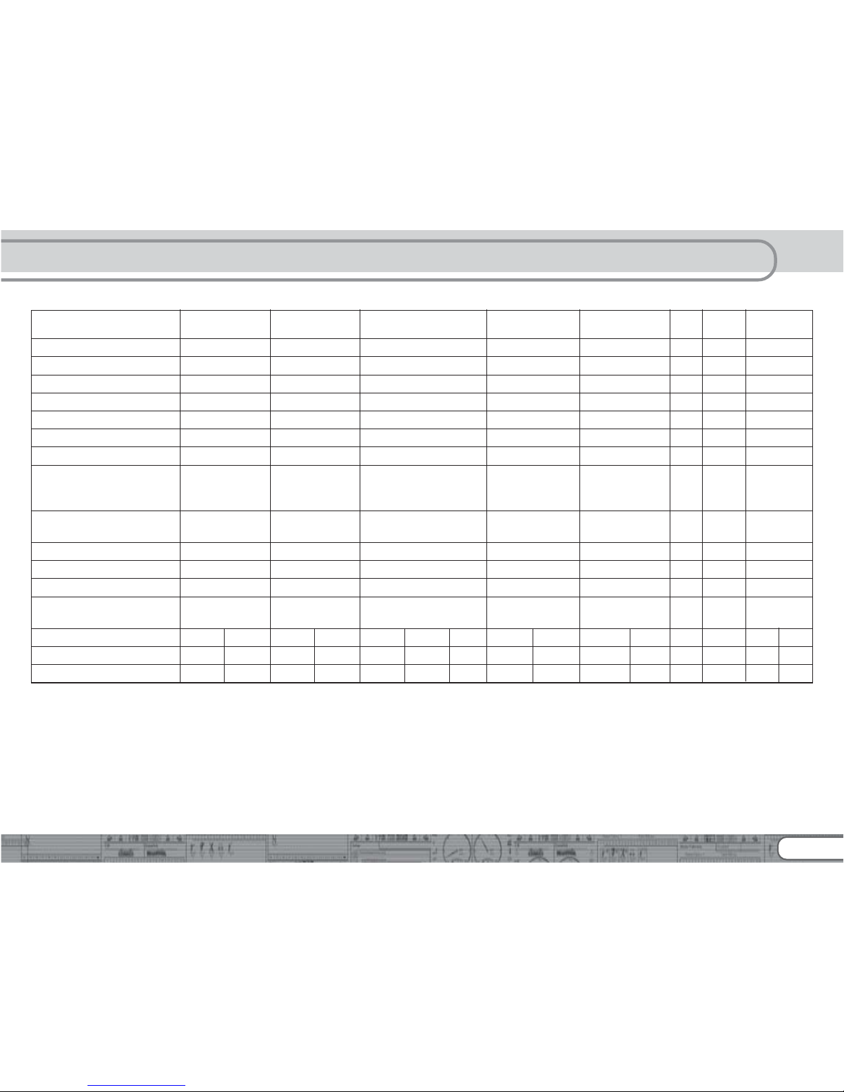
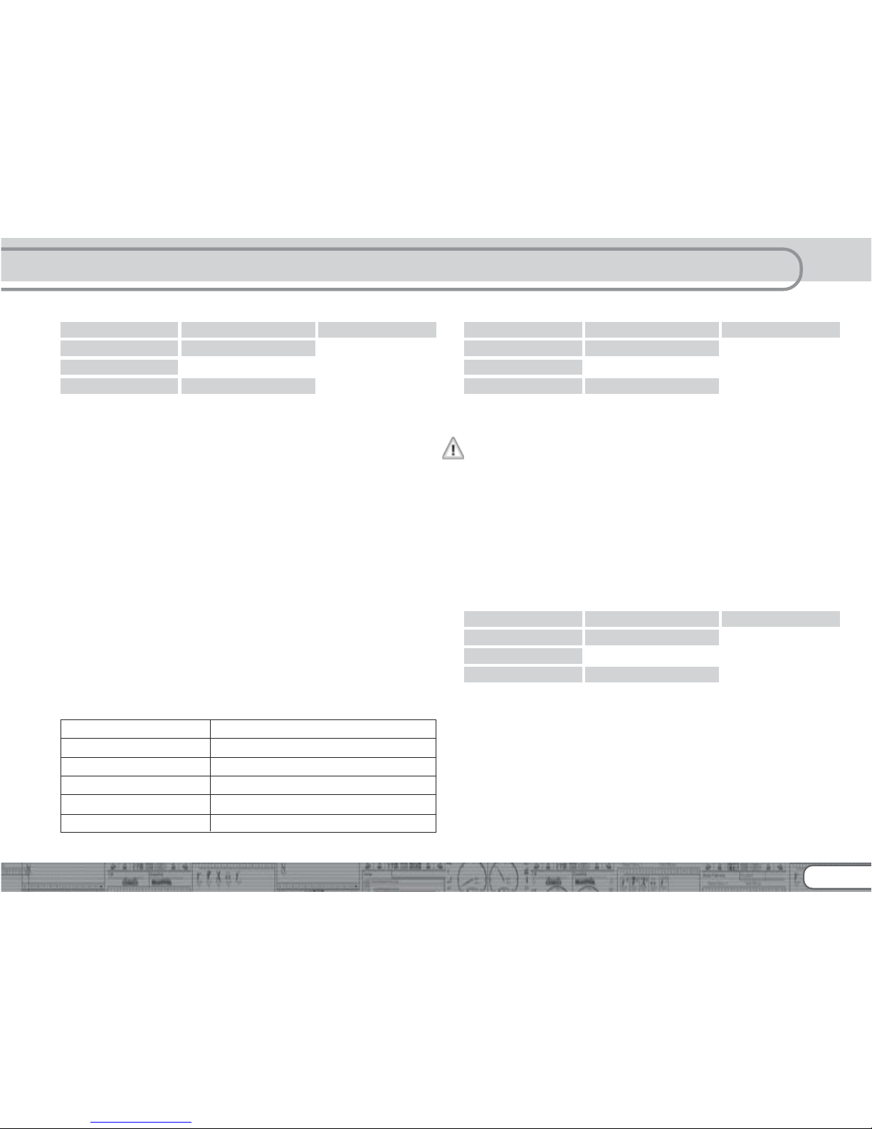
5.1.1. LokPilot V3.0 Decoders – an Overview
LokPilot micrLokPilot micr
LokPilot micrLokPilot micr
LokPilot micr
oo
oo
o
LokPilot micrLokPilot micr
LokPilot micrLokPilot micr
LokPilot micr
oo
oo
o
LokPilot V3.0LokPilot V3.0
LokPilot V3.0LokPilot V3.0
LokPilot V3.0
LokPilot V3.0LokPilot V3.0
LokPilot V3.0LokPilot V3.0
LokPilot V3.0
LokPilot V3.0 LokPilot V3.0
LokPilot V3.0 LokPilot V3.0
LokPilot V3.0
LokPilot LokPilot
LokPilot LokPilot
LokPilot
LokPilot LokPilot Fx LokPilot LokPilot Fx
LokPilot LokPilot Fx LokPilot LokPilot Fx
LokPilot LokPilot Fx
V3.0V3.0
V3.0V3.0
V3.0
V3.0 DCCV3.0 DCC
V3.0 DCCV3.0 DCC
V3.0 DCC
DCCDCC
DCCDCC
DCC
M4M4
M4M4
M4
XL V3.0 XL V3.0
XL V3.0 XL V3.0
XL V3.0
Fx micr Fx micr
Fx micr Fx micr
Fx micr
o V3.0o V3.0
o V3.0o V3.0
o V3.0
DCC Operation Ok Ok Ok Ok - Ok Ok Ok
Motorola Operation Ok - Ok - O k Ok Ok Ok
M4 Operation - - - - O k - - -
Selectrix Operation Ok Ok Ok - - - - -
Analogue DC Operation Ok O k Ok Ok Ok Ok Ok Ok
Analogue AC Operation - - O k - O k Ok Ok Ok
DCC programming modes Ok Ok Ok Ok - Ok Ok Ok
Motorola programming mode
using 6021, Mobile Station,
Central Station Ok - Ok - Ok Ok Ok Ok
M4 programming including
automatic recognition - - - - O k - - -
RailCom option Ok Ok Ok Ok - Ok Ok Ok
continuous motor current 0.75A 0.75A 1.1A 1.1A 1.1A 3.0A - -
function output current 2/140mA 2/140mA 4/250 mA 4/250mA 4/250mA
8/600mA
4/140mA 6/250mA
integrated PowerPack
buffer capacitor - - - - - - -
connection type 6 pin 6 pin 6 pin 6 pin 8 pin 6 pin 21MTC 8 pin 6 pin 8 pin 21MTC
screwing 6 pin 8 pin
21MTC
direct harness direct harness harness harness harness harness harness
terminal
harness harness
ESU item-number 52688 52687 52685 52684 52610 52612 52614 52611 52613 61600 61601 51702 52624 52620 52621
5.1.3. LokPilot V3.0 DCC
The LokPilot V3.0 DCC is a thoroughbred DCC decoder. Except
for the Motorola® and Selectrix® protocol, it supports all
functions of the LokPilot V3.0. In analogue mode, it can only
operate on DC powered layouts. The LokPilot V3.0 DCC is best
suited for the DCC purist who does not require multi-protocol
operation and does not want to pay for it either.
LokPilot V3.0 decoders - an overview
5.1.4. LokPilot V3.0 M4
The LokPilot V3.0 M4 is designed for the M4 data format. Besides
the new central units for Märklin systems with the mfx®-data
format, it is also suitable for the older models such as Delta or
control unit 6020 resp. 6021. Of course, you may also run it
with analogue alternating current. The LokPilot V3.0 M4
represents the first choice for all friends of the „new world“.

8
5.1.5. LokPilot XL V3.0
The LokPilot XL V3.0 is a powerful multi-protocol decoder for
Motorola® and DCC best suited for the larger scales: It can handle
a motor current of 3.0A and offers 8 function outputs. Furthermore, dirty tracks finally do not spoil your fun anymore due to
the integral „PowerPack“ energy buffer.
5.1.6. LokPilot micro V3.0
The LokPilot micro V3.0 is a real multi talent. Besides DCC and
Motorola® and Selectrix® and a maximum current draw of 0.75A,
it is ideal for the small scales with little room for decoders.
5.1.7. LokPilot micro V3.0 DCC
The LokPilot micro V3.0 DCC is a real power package: with a
permitted current draw of 0.75 A this DCC decoder with
RailCom® option offers the best solution for small locomotives
in N and TT-scale as well as small H0 locomotives with limited
room.
5.1.8. LokPilot Fx V3.0
The LokPilot Fx V3.0 is intended for vehicles without motors. It
has 6 function outputs. It supports the Motorola® as well as the
DCC format and is at home on analogue DC and AC layouts.
This LokPilot is ideal for using it in combination with another
LokPilot or LokSound decoder.
5.1.8. LokPilot Fx V3.0
The LokPilot micro FX V3.0 decoder is used for locos which are
too small for its „big brother“, the LokPilot Fx V3.0. It has four
function outputs and can be operated with the Motorola® and
the DCC format. It also proves it´s worth on analogue DCC
layouts.
5.2. General Properties of all Decoders
5.2.1. Operating Modes
All LokPilot V3.0 decoders (with the exception of the pure DCC
decoders) are true multi-protocol decoders with automatic
detection of the operating mode „on-the-fly.“ The decoder
analyses the track signal and filters out the part that is reserved
for it. Changing from digital to analogue and back represents
no problem whatsoever. This is important in case your storage
(fiddle) yard still works in analogue mode. Furthermore, all
LokPilot decoders support the relevant brake modes such as
ROCO®, Lenz® or Märklin® and stop as intended. LokPilot
decoders achieve the maximum compatibility with the operating
system in order to enable you to simulate even some unusual
operational requirements.
Provided the digital system supports them, then the LokPilot V3.0
supports and automatically detects the DCC protocol with 14,
28, or 128 speed steps. Of course, operation with the long 4digit addresses is possible as well.
Contrary to the original Märklin®-decoders, LokPilot V3.0
decoders support up to 255 addresses and 28 speed steps in
Motorola® mode. With the appropriate command station such
as for instance the ESU ECoS, you can expand the system limits
of the Motorola® system considerably.
Some LokPilot decoders also support the Selectrix® mode or M4
mode (mfx® compatible).
5.2.2. Motor Control
The most important function of digital decoders is motor control.
All LokPilot V3.0 decoders are designed for universal use and
therefore can control all commonly available DC motors,
regardless if they are by ROCO®, Fleischmann®, Brawa®,
Mehano®, Bemo®, LGB®, Hübner®, Märklin® or others.
Coreless motors (such as Faulhaber® or Maxon®) also work fine
with LokPilot. You may continue to use any universal motors
provided you replace the stator coils with a permanent magnet.
LokPilot V3.0 M4

9
You will find more info on this topic in chapter 6.6.4.2.
Fourth generation load compensation works with 16 resp. 32
kHz and assures extremely silent operation, particularly with
coreless motors. Due to 10-bit technology, your locomotives will
crawl at a snail’s pace if so desired. Load compensation is easily
adjustable to various motor and gear combinations (compare
with chapter 11).
With Dynamic Drive Control (DCC), you can limit the influence
of load control. Thus, you can control your locomotive in small
throttle notches for instance in the yard or on turnouts while the
locomotive responds like the prototype at high speed on the
main line (for instance when climbing a gradient). In other words,
if you do not change the throttle setting then the locomotive will
slow down up the hill, as does the prototype. There is more info
on this in chapter 11.4.
The minimum and maximum speed of the LokPilot V3.0 is
adjustable by setting three points or the speed table with 28
entries. The table is effective for all speed step ratings (14, 28,
and 128 speed steps); many decoders by others do not offer this
feature. Due to unique load compensation by ESU, there are no
visible jerks between speed steps – even in 14-speed-step-mode.
5.2.3. Analogue Mode
Quite a few LokPilot decoders replace analogue directional relays.
Therefore, you can not only set the starting speed and the
maximum speed as well as pre-select which functions should be
active in analogue mode: even load compensation works in
analogue mode! Therefore, LokPilot V3.0 decoders are ideal for
analogue locomotives: finally, you can slow down your older,
fast running locomotives.
5.2.4. Functions
Standard features for LokPilot V3.0 decoders include the following
features: acceleration and brake times can be separately adjusted
and switched, and of course, you can switch the shunting mode.
The brightness of all function outputs can be separately set and
allocated to the desired function buttons (function mapping).
There is a wide range of options: dimmer, flickering firebox, gyro-
light and mars-light, flash and double flash, blinker and alternate
blinker as well as switch functions with timers (e.g.: for Telex)
and a special coupler function for remote controlled couplers by
Krois® and ROCO®.
The unique ESU function mapping enables you to allocate every
function to the function buttons F1 to F15; even multiple
allocations are possible. You will find more info on this in chapter
12.
5.2.5. Programming
Where intended, LokPilot decoders support all programming
modes including POM (Programming-On-the-Main). You can use
any NMRA-DCC compatible command station for this purpose.
Even with the Märklin® central units 6020®, 6021®, Mobile
Station® and Central Station® all settings are adjusted
electronically. Most LokPilot V3.0 decoders support a simple-touse programming procedure. Owners of the ESU ECoS enjoy an
even more comfortable method of programming: you can read
all possible settings in plain text on the large display and easily
adjust them – even during operation!
5.2.6. Operational Reliability
LokPilot decoders store the current operating status. Thanks to
this data storage, the decoder will start again as quickly as
possible after a service interruption. Some decoders also have
an integral „PowerPack“ that assures continuous power even in
case of poor electrical contact.
5.2.7. Protection
All function outputs as well as the motor output have protection
against overload and short circuit. We want you to enjoy your
LokPilot decoders for a long time.
5.2.8. Future included
All LokPilot V3.0 decoders are suitable for firmware updates due
to the flash memory. You may add new software functions at a
later stage.
General Properties of all Decoders
10
6. Installing the Decoder
6.1. Requirements for Installation
The locomotive must be in perfect technical condition prior to
the conversion: Only a locomotive with faultless mechanical
properties and smooth running characteristics in analogue mode
is worth converting to digital. Check and replace all wear and
tear parts such as motor brushes, wheel contacts, light bulbs
etc., if necessary.
Please take note of the remarks in chapter 3 in order to prevent
possible damage of the decoder during installation!
6.2. Installing the Decoder
The components on the decoder must under no circumstances
touch any metal parts of the locomotive since this could lead to
short circuits and damage or even destruction of the decoder.
Therefore, all LokPilot decoders (with the exception of the ones
with the 21MTC-interface) come with a protective shrink sleeve.
Never wrap the decoder in insulating tape. Should there be no
ventilation around the decoder, then this may lead to a heat
build-up and ultimately to the destruction of the decoder. Rather apply the insulating tape to the metal parts of the locomotive.
Mount the decoder at a suitable location. In most model
locomotives, there is a dedicated space for the decoder. To hold
the decoder in place use double sided adhesive tape or some
(just a little) hot glue.
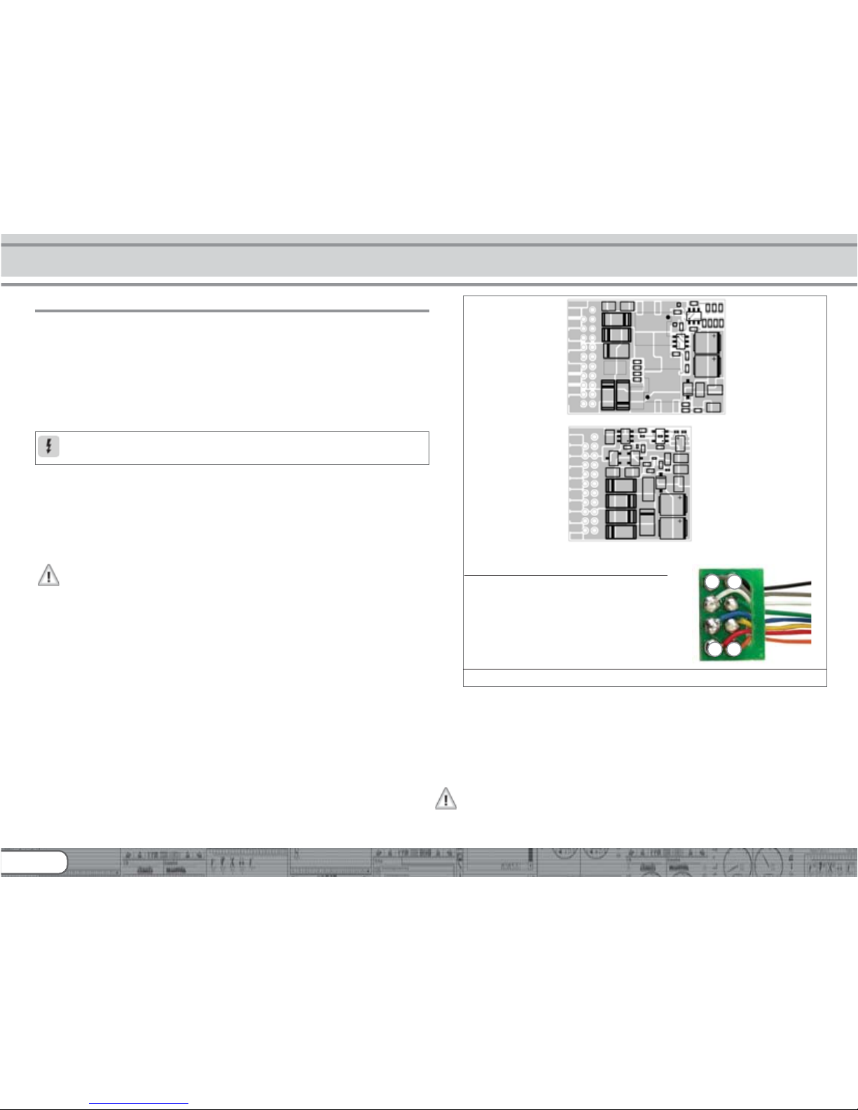
6.3. Locomotives with 8-pole NEM 652-Interface
Some LokPilot V3.0 decoders are supplied with an 8-pole interface
as per NEM 652 (refer to Fig 1). Installation in locomotives with
this interface is particularly easy:
•Remove the locomotive body. Please observe the instructions in
the manual of your locomotive!
•Remove the dummy plug from the socket and keep it in a suitable
place for later use.
Installing the Decoder
Figure 1: LokPilot V3.0 (DCC/M4), LokPilot Fx V3.0 - NEM652
•Insert the plug of the decoder in such a way that pin 1 of the
plug (this is the side with the red / orange wires) sits next to the
corner of the socket that is usually marked with *, +, • or 1.
Please make sure that the pins are straight when inserting the
plug.
Do not rely on the assumption that the wires of the harness have
to face in a certain direction: the only reliable reference is the
marking of pin 1.
52610 LokPilot V3.0
52611 LokPilot V3.0 DCC
61600 LokPilot V3.0 M4
52620 LokPilot Fx V3.0
AUX2
----
----
--
right motor terminal
----
----
--
right track connection
----
----
--
rearlight
----
----
--
common(+pole)
----
----
--
AUX1
----
----
--
headlight
----
----
--
left track connection
----
----
--
left motor terminal
----
----
--
AUX2
----
----
--
(orange) AUX3
----
----
--
right track connection
----
----
--
rearlight
----
----
--
common(+pole)
----
----
--
AUX1
----
----
--
headlight
----
----
--
left track connection
----
----
--
(gray) AUX4
----
----
--
Pin Description Color
1 right motor terminal orange
2 rear light yellow
3 output AUX1 green
4 left track connection black
5 left motor terminal gray
6 headlight white
7 common (+pole) blue
8 right track connection red
4
5
1
8
11
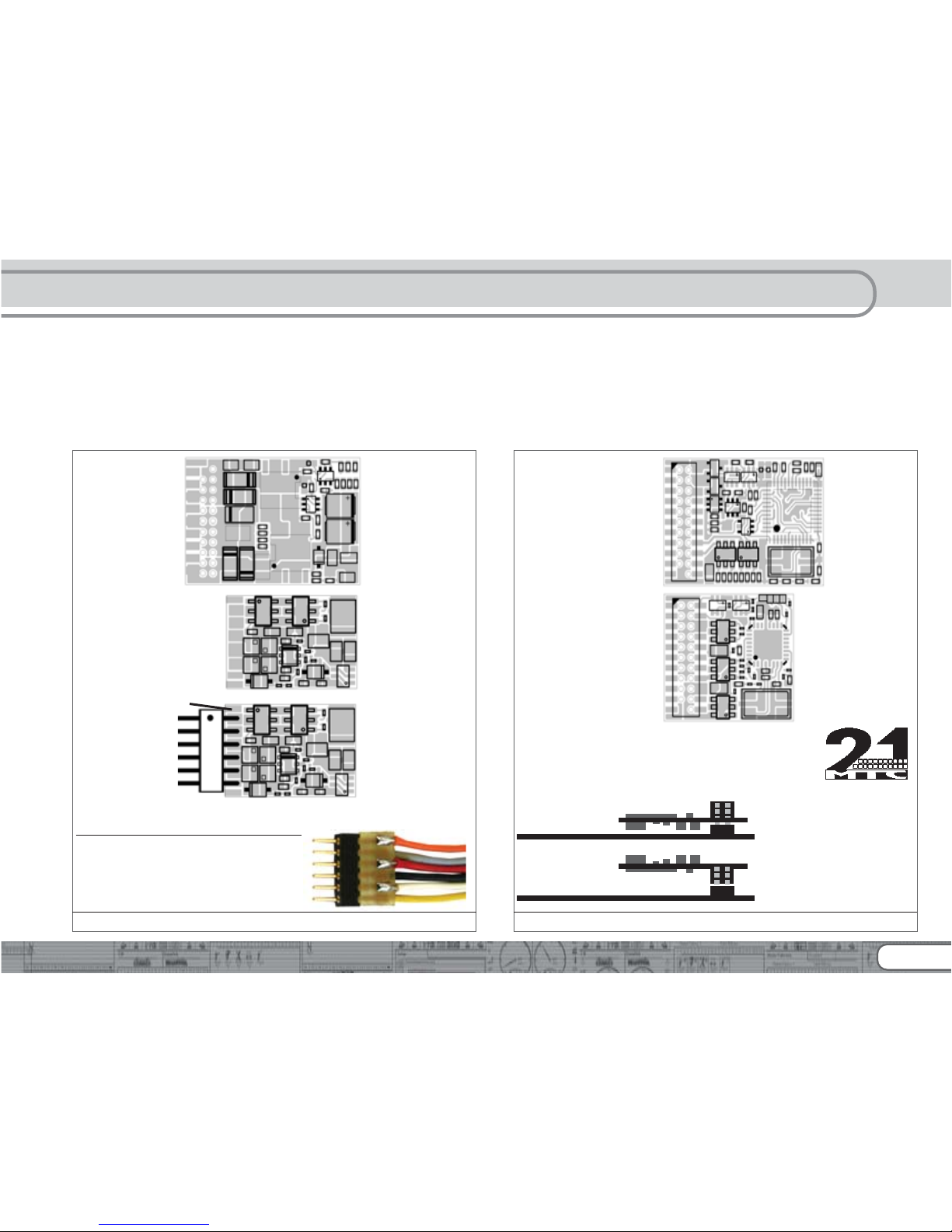
6.4. Locomotives with 6-pole NEM 651-Interface
Some LokPilot V3.0 decoders have a 6-pole NEM 651 plug (as
per Fig. 2). Installation in locomotives with this interface is
particularly easy:
•Remove the locomotive body. Please observe the instructions in
the manual of your locomotive!
•Remove the dummy plug from the socket and keep it in a suitable
place for later use.
•Insert the plug of the decoder in such a way that pin 1 of the
plug (this is the side with the red / orange wires) sits next to the
corner of the socket that is usually marked with *, +, • or 1.
Please make sure that the pins are straight when inserting the
plug.
Figure 2: LokPilot V3.0 (DCC), LokPilot micro V3.0 - NEM651
52611 LokPilot V3.0
(violet) AUX2
----
----
--
right motor terminal
----
----
--
right track connection
----
----
--
rearlight
----
----
--
(blue) common(+pole)
----
----
--
(green) AUX1
----
----
--
headlight
----
----
--
left track connection
----
----
--
left motor terminal
----
----
--
Pin Description Color
1 right motor terminal orange
2 left motor terminal gray
3 right track connection red
4 left track connection black
5 headlight white
6 rear light yellow
52687 LokPilot micro V3.0
52684 LokPilot micro V3.0
(blue) common(+pole)
----
----
--
right motor terminal
----
----
--
left motor terminal
----
----
--
right track connection
----
----
--
left track connection
----
----
--
headlight
----
----
--
rearlight
----
----
--
soldering pad AUX1 (Logic level!)
----
----
--
52686 LokPilot micro V3.0
52685 LokPilot micro V3.0
right motor terminal
left motor terminal
right track connection
left track connection
headlight
rearlight
(blue) common(+pole)
--
--
-
--
--
-
soldering pad AUX1 (Logic level!)
DCC
DCC
Figure 3: LokPilot V3.0, LokPilot V3.0 M4 - 21MTC
52614 LokPilot V3.0
22 right track
21 left track
20 GND
19 right motor
18 left motor
17 n.c.
16 common (+)
15 AUX1
14 AUX2
13 AUX3
12 VCC
n.c. 1
n.c. 2
n.c. 3
AUX4 4
n.c. 5
n.c. 6
rearlight 7
headlight 8
n.c. 9
n.c. 10
Index pin 11
22 right track
21 left track
20 GND
19 n.c.
18 n.c.
17 n.c.
16 common (+)
15 AUX1
14 AUX2
13 AUX3
12 VCC
n.c. 1
n.c. 2
n.c. 3
AUX4 4
n.c. 5
n.c. 6
rearlight 7
headlight 8
n.c. 9
n.c. 10
Indexpin 11
52621 LokPilot Fx V3.0
Insertion of decoder with
Connector to the top
(e.g.. Hobby trade, HAG, Märklin)
How to connect the decoder:
locomotive pcb
locomotive pcb
Insertion of decoder with
connector to the bottom
(e.g. Brawa)
12
6.5. Locomotives with 21MTC Interface
Some LokPilot decoders are available with a variant of the 21MTC
interface as per Fig. 3. Installation in locomotives with this
interface is particularly easy since the plug-socket connector
facilitates the mechanical fixing as well.
•Remove the locomotive body. Please observe the instructions in
the manual of your locomotive!
•Remove the dummy plug from the socket and keep it in a suitable
place for later use
•Search for the missing pin in the plug on the circuit board of the
locomotive. The missing pin serves as the marker. Memorise its
location.
•You can insert the decoder in two ways: either the pins are put
through the decoder; the socket of the decoder remains visible
after installation (mounting on top) or the decoder is inserted in
such a way that the pins go straight into the socket. Once the
decoder sits in the socket, the socket is hidden from view. This
method is common for Brawa locomotives.
•Which of the two mounting positions is the correct one depends
solely on the locomotive. The position of the marker-pin is the
crucial indicator.
•Plug the decoder into the socket in such a way that the locomotive
interface corresponds with the decoder.
•Do not apply too much pressure when inserting the plug. The
decoder must go in without force.
•Check if the decoder sits correctly.
6.5.1. Connecting C-Sine motors („SoftDrive-Sinus“)
The LokPilot decoder cannot drive the newer Märklin®-models
with C-Sine motors (also called „SoftDrive-Sinus“) directly. To
facilitate this, a circuit board supplied with the locomotive is
required. Märklin uses the 21MTC interface installed on this
circuit board and thus utilises the normal motor commands form
the decoder for the exchange of information.
Both the LokPilot V3.0 and the LokPilot V3.0 M4 with the 21MTC
interface are suitable for controlling the C-Sine control electronics
provided some parameters are set accordingly. Chapter 11.5.
explains the necessary steps.
Some Trix® locomotives have the same C-Sine motor; however,
the control electronics in Trix® locomotives communicate in a
different manner with the decoder. Currently it is not possible to
run such locomotives with LokPilot decoders even though they
have the same (mechanically identical) interface.
6.6. Locomotives without Interface
All LokPilot decoders have the interface (plug). There is no „wiresonly“ version. Please remove the plug at the end of the harness
should this become necessary.
Please do not extend any wires at the decoder end. If necessary
use an extension harness (also refer to chapter 18).
Installing the Decoder
13
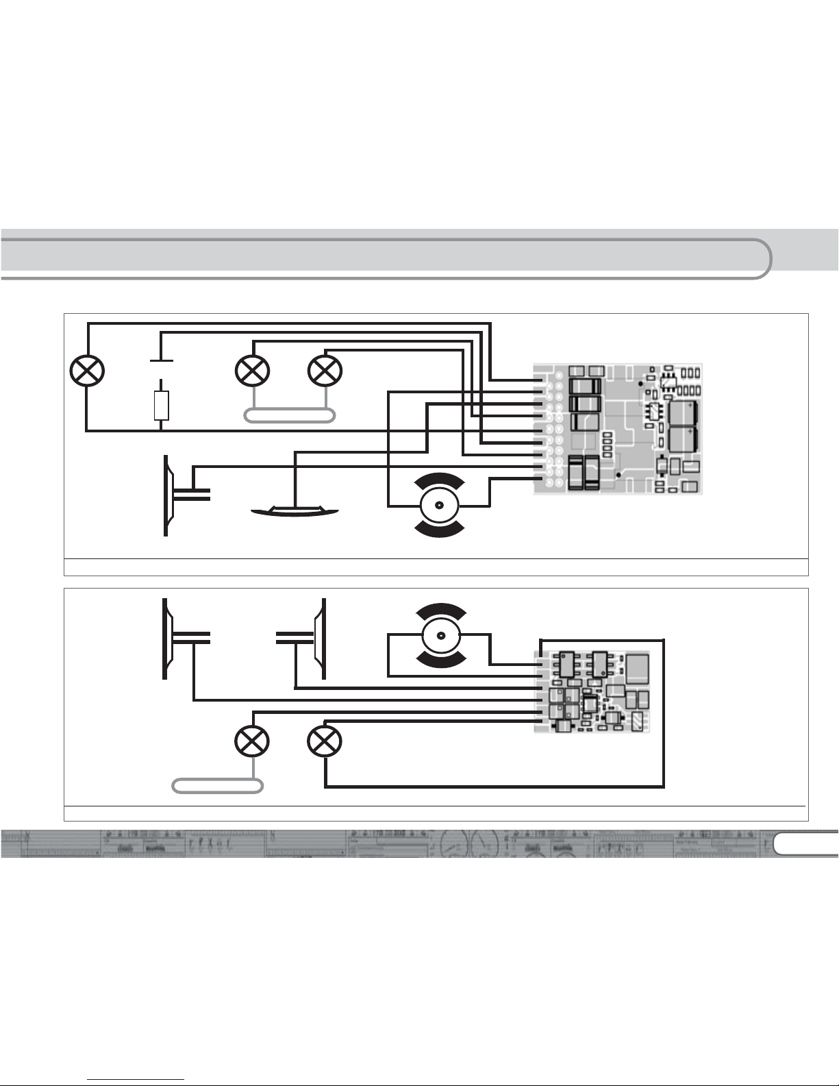
6.6.1. Wiring Diagram for LokPilot or LokPilot micro
Figure 5: Wiring Diagram for LokPilot micro V3.0, LokPilot micro V3.0 DCC (examples)
motor
52687 LokPilot micro V3.0
52684 LokPilot micro V3.0 DCC
orangegray
black red
wh ite yellow
Head
Lights
Rear
Lights
chassis
orange
gray
red
black
white
yellow
blue (optional, instead of chassis connection)
violet gr ee n yellow white
AUX2
AUX1 Rear
Light
Head
Light
gray
orange
motor
red
chassis
52610 LokPilot V3.0
52611 LokPilot V3.0 DCC
61600 LokPilot V3.0 M4
violet
orange
red
yellow
blue
green
white
black
gray
R
black
Figure 4: Wiring Diagram for LokPilot V3.0, LokPilot V3.0 DCC, LokPilot V3.0 M4 (examples)
14
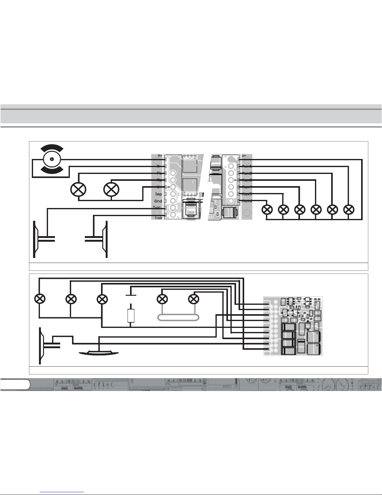
6.6.2. Wiring Diagram for a LokPilot XL Decoder
Installing the Decoder
Motor
Head
Lights
Rear
Lights
right motor terminal
left motor terminal
Figure 6: Wiring diagram for LokPilot XL V3.0 (wiring example)
left track connection
right track connection
Common (+Pole)
AUX6 AUX5 AUX4 AUX3 AUX2 AUX1
gre en yellow white
AUX1 Rear
Lights
Head
Lights
red
chassis
52620 LokPilot Fx V3.0
violet
orange
red
yellow
blue
green
white
black
gray
R
black
Figure 7: Wiring diagram for LokPilot Fx V3.0 (wiring example)
violet
AUX2
orange
AUX3
gray
AUX4
15
•Connect the red wire to the right rail pickup or the centre pick
up in AC models.
•Connect the black wire to the left rail pickup or the chassis in
AC models.
•Connect the orange wire with the motor terminal, which originally
lead to the right wheel pick up (centre pick up in AC models).
•The grey wire goes to the terminal, which originally connected
to the left rail (chassis for AC models).
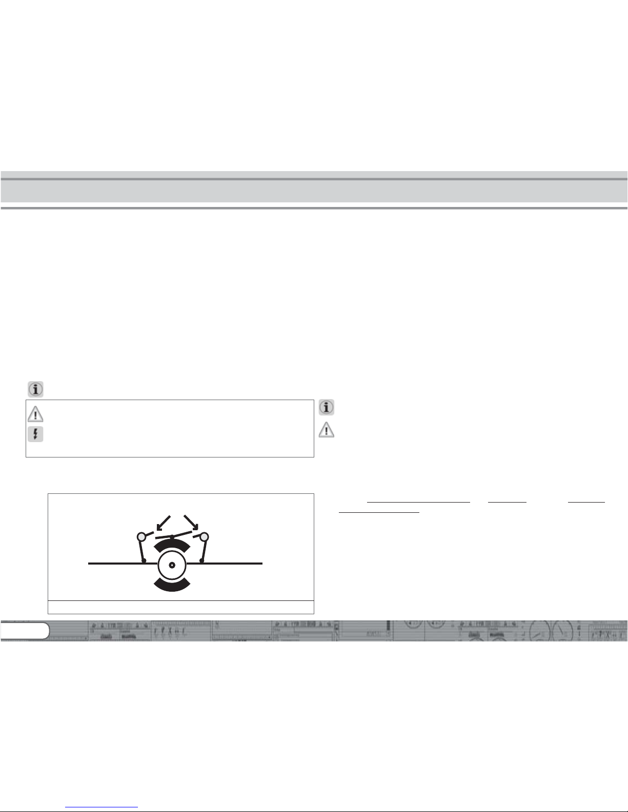
6.6.4.1. Connecting DC and Coreless Motors
You may use all DC motors commonly used for model trains
provided they do not exceed the current limit of the decoder.
In some cases with the 5-pole High Performance Drive by
Märklin®, you may find three anti-interference capacitors:
the two capacitors connected directly to the motor leads and the
motor housing MUST be removed (also refer to Fig. 9 on the
following page).
6.6.3. Colour Coding by Märklin®
Märklin® uses a different colour coding system compared to the
DCC colours. Please refer to Fig. 8 for more information.
6.6.4. Motor and Track Connections
Firstly, please cut all wires installed in the locomotive. Take special
care to remove any connections to the chassis: the motor leads
must be positively potential-free, in other words the may not
have any contact to the chassis or body or the wheels and wheel
contacts. It is particularly easy to overlook such connections in
Fleischmann® locomotives.
Make notes of which motor lead connects the motor with the
right and the left wheel contact. This avoids mistakes and assures
that your locomotive runs in the right direction.
Please check all connections with an Ohmmeter. Search for
short circuits, particularly between the motor leads and the wheel
contacts.
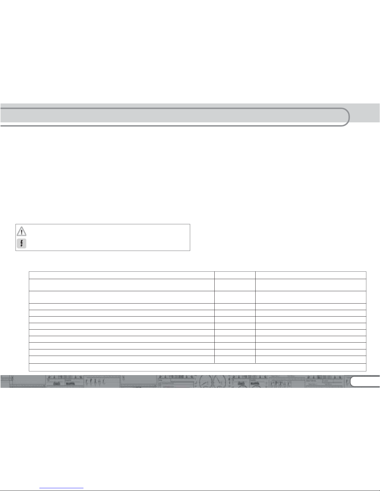
Figure 8: Colour coding by Märklin® in contrast to the DCC wiring code
Description Märklin color ESU color (following NMRA DCC standard)
AC: Power pickup show („Schleifer“) (Center Rail) red red
DC: right track connection
AC: Outside Rails brown black
DC: left track connection
left motor terminal blue orange
right motor terminal green gray
common (rectified track voltage) (+Pole) for function outputs orange blue
function output Rearlights yellow yellow
function output Headlights gray white
function output AUX1 brown/red green
function output AUX2 brown/green violet
function output AUX3 (logic level only occasionally, depending on decoder type) brown/yellow function output AUX4 (logic level only occasionally, depending on decoder type) brown/white -
16
6.6.4.2. Connecting Universal Motors with HAMO-Conversions
Do not wire universal motors installed in many older Märklin®
locomotives (also known as AC motors) directly to LokPilot
decoders. You must modify the motor by first installing permanent magnets – so called HAMO magnets. You may purchase
these magnets from your ESU dealer.
We supply three types of magnets. Please refer to chapter 18.2.
for more information regarding motor conversions with permanent magnets.
6.7. Connecting Additional Functions
You can wire any kind of load such as light bulbs, LEDs (light
emitting diodes), smoke generators or similar devices to the
function outputs provided the maximum current draw is less than
that of the decoder output.
The permitted maximum current draw per function output is listed
in chapter 20 under „Technical Data.“
Please make sure that the load does not exceed the permitted
maximum current and there are no short circuits. The outputs
of the LokPilot have protection but if an external voltage is
applied, the outputs may suffer damage or destruction.
6.7.1. Overload Protection of Function Outputs
The function outputs of LokPilot decoders have electronic
protection against overload and short circuit. The decoder keeps
checking the sum of all function output currents. If the current
is too high, the decoder will switch off the outputs. After about
1 second, the decoder tries to switch them on again. Should the
current still be too high – perhaps due to a short circuit – the
same procedure starts again.
When using light bulbs (incandescent lamps) please note the
following: they draw a very high „inrush current“ when they are
switched on, that becomes lower after a few moments. Therefore,
it can happen with 12V bulbs that the headlights „flash“ briefly
during switch-on and then extinguish due to the overload
protection of the decoder. It is important to install the correct
bulbs.
6.7.1.1. Suitable Light Bulbs
Only install bulbs rated 16V or higher and with a nominal current,
that does not exceed 50 mA.
Many older models by ROCO® and Fleischmann® have 12V bulbs
installed. They draw a high current, become very hot, and may
cause damage to the locomotive. Replace them with 16V bulbs.
6.7.2. Connecting the Light Outputs as well as AUX1 and AUX2
This procedure depends on the wiring of the lights and auxiliary
functions in the locomotive:
a) The
lamps / function outputs are insulated from the common
pole (ground) (i.e.: the locomotive chassis); therefore they are
potential free. Fig. 4 shows the correct wiring for the outputs
AUX1 and AUX2. The functions of the locomotive must be potential-free, in other words there may not be any other connection
to the function besides the wires from the decoder. The voltage
at these outputs is about 1.5V lower than the track voltage. The
blue wire is the „plus-pole“; the function output the „minuspole.“
If LEDs are installed (also refer to Fig. 4, output AUX1), then a
resistor must be wired in series with the LEDs. It should have a
Installing the Decoder
Figure 9: 5-pole Märklin® motor
greyorange
remove capacitors!
17
rating of between 470 Ohms and 2.2 kOhms. Running the LEDs
without this resistor will lead to their destruction!
b) The
lamps / function outputs are wired (together) against the
chassis of the locomotive (as in most locomotives by Märklin®
as well as in most older locomotives by Fleischmann® and
ROCO®). This scenario is illustrated for the light outputs in Fig.
4 (the headlights can of course also be wired as in „a)“). The
wiring is simpler but the available voltage is about half.
This type of connection is not suitable for multi-protocol
operation. Both M4 and Motorola® packets are asymmetrical.
Therefore, the function outputs do not have continuous power.
This leads to a rhythmic flicker of the headlights (pulsing) that
becomes particularly obvious with LEDs. Furthermore, the
headlights will only work in one direction in analogue DC mode.
Whether it will be the forward lights or the backup lights depends
on which way you have placed your locomotive on the track.
•Solder the backup lights to the yellow wire, the headlights to
the white one.
•The green wire connects to the function output AUX1.
•The purple wire goes to the function output AUX2.
If your locomotive is wired according to option b), then it is rea-
dy for use. Otherwise, you must connect the remaining wires of
all bulbs and functions together to the blue wire. This pole may
not have any connection to the chassis!
As shown in Fig. 4 it is possible to use both options in the same
locomotive.
6.7.3. Purpose of AUX3 and AUX4
6.7.3.1. LokPilot with 21MTC Interface
LokPilot decoders with 21MTC interface have two additional
outputs besides the 4 standard outputs, namely AUX3 and AUX4.
Since they are pure „logic-outputs,“ it is not possible to connect
any external loads directly. External power transistors are required.
Connect AUX3 and AUX4 via the interface; there are no wire
leads. In terms of their functionality, AUX3 and AUX4 are equal
to the other outputs.
6.7.3.2. LokPilot Fx V3.0
The LokPilot Fx V3.0 offers up to 6 function outputs (also refer to
Fig. 7). You can access the outputs AUX3 and AUX4 via the
orange resp. the grey wire.
For all other LokPilot decoders the orange and grey wires are the
motor leads. The LokPilot Fx V3.0 is an exception.
6.7.3.3. LokPilot Fx micro V3.0
The LokPilot Fx micro V3.0 offers up to 4 function outputs. You
can access the outputs AUX1 and AUX2 via the orange resp. the
grey wire.
For all other LokPilot decoders the orange and grey wires are the
motor leads. The LokPilot Fx V3.0 is an exception.
6.7.4. Suitable Smoke Generators
Unfortunately, it is not an easy task to find the right smoke
generator for each locomotive. The amount of smoke generated
depends on the following factors:
a) Track voltage
The track voltage varies depending on the command station.
Therefore, it is possible that a locomotive generates smoke
when driven by one digital system but does not generate any
smoke with another system. Even 1V variation makes a big
difference.
b) Type and tolerance of the Seuthe smoke generator and the
smoke distillate
Seuthe smoke generators have considerable production
tolerances. Therefore, it is possible that one unit works
perfectly well while another does not. Type of distillate and
filling level have an influence as well.
c) Setting the decoder output
For correct smoking action you should set the AUX output to
„Dimmer“ as well as full „Brightness.“ More info in chapter
12.
18
d) Connecting the smoke generator
Most smoke generators are wired against the chassis.
Therefore the smoke generator only receives current in every
second half cycle. How much power gets to the smoke
generator depends on your command station and the digital
protocol. Generally, Seuthe type 11 is recommended, but it
does not get enough power and therefore does not smoke
satisfactorily.
There are two options on how to solve this problem:
Solution 1: Using the Seuthe No. 10. This type is intended for
analogue operation and draws a relatively high current. Subject
to its tolerance levels, it may trigger the overload protection of
the decoder. In this case, you must wire a relay (ESU No. 51963)
into the circuit or you slightly reduce the „Brightness“ of the
output.
Solution 2: Using the Seuthe No. 11. Do not wire it against the
chassis but rather use the blue wire for the second pole („U+“).
This prevents the asymmetric track signal from interfering with
the smoke generator. It represents the best solution but is
sometimes a bit difficult in terms of wiring.
6.8. Connecting Capacitors
On many older layouts, current pick up of locomotives is not very
reliable. Therefore, power interruptions may cause a stop or
jerky movement when the locomotive travels over turnouts at
low speeds. This can be overcome with buffer capacitors (100
uF / 25V or higher show the desired results). If desired you may
connect them to the LokPilot decoders.
Soldering wires onto a decoder requires quality soldering
equipment and experience. Our warranty does not cover
damage caused by inappropriate soldering. Consider carefully
if you really need that capacitor.
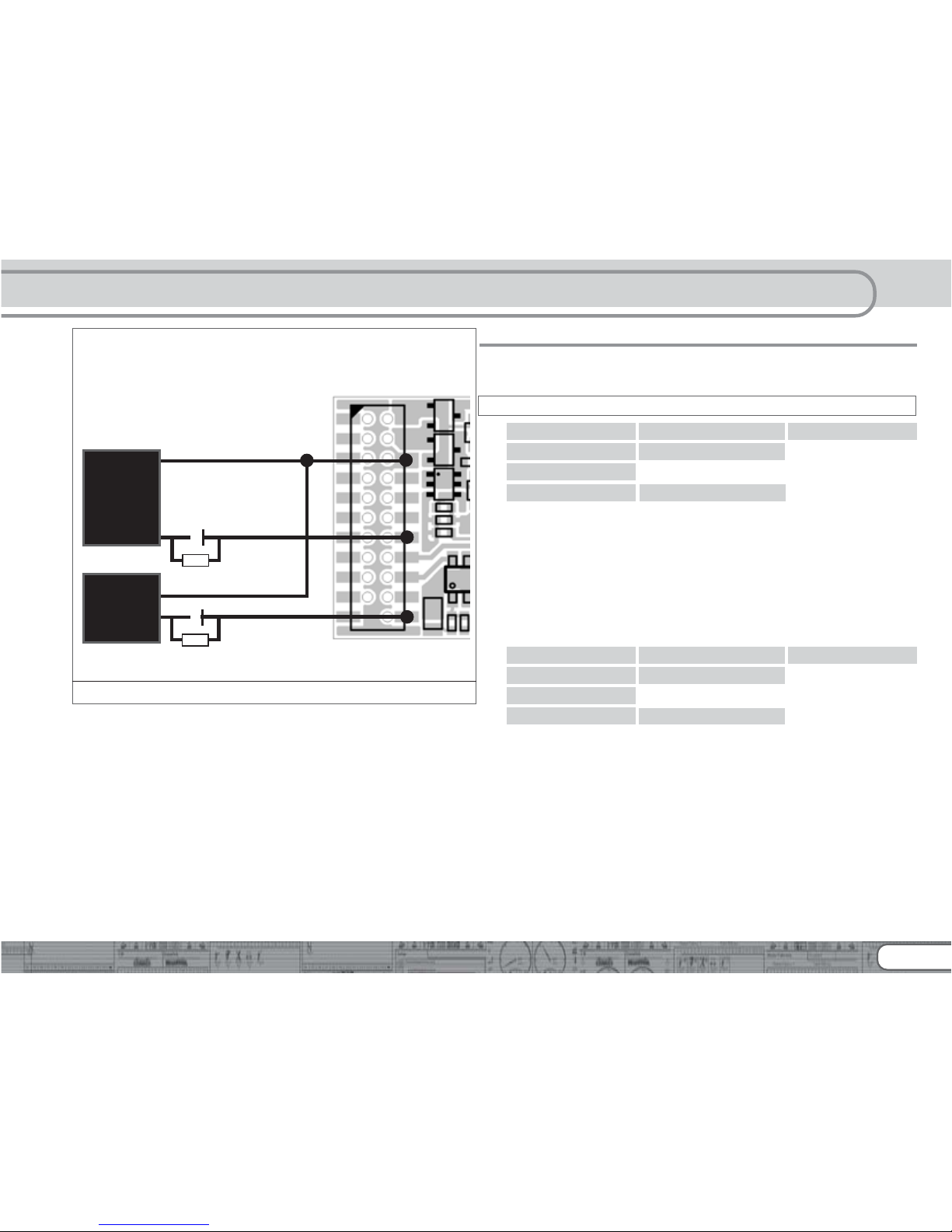
6.8.1. All LokPilot H0
You can connect two larger capacitors as per the circuit in Fig.
11. One buffers the motor output, the smaler capacitor supports
the microcontroller of the decoder. The capacitor is charged via
a resistor (100 Ohms) thus preventing the digital system from
interpreting the charging current as short circuit at the time of
switch-on. The diode makes sure that the energy of the capacitor
is fully available when required.
However, you may not run this locomotive on AC layouts
anymore. Risk of destruction!
Disconnect / remove the capacitor prior to programming with
the ESU LokProgrammer!
6.8.2. Integral „PowerPack“ in LokPilot XL V3.0
The LokPilot XL V3.0 comes ex works with a particularly powerful
energy buffer. This „PowerPack“ allows your locomotive to keep
running for 2 seconds without power. The PowerPack does not
have to be configured, it simply works anytime. Please consider
the following aspects:
•The PowerPack only operates in digital mode. It automatically
turns off on analogue layouts.
•It may take up to two minutes to fully charge the capacitor
(„GoldCap“). Therefore, the time bridged with the energy buffer
depends on the current draw of your locomotive and the chargeup time.
•You may notice a certain reduction in the speed of a fast running
locomotive whenever the PowerPack provides power to the
locomotive. This is quite normal and does not represent faulty
behaviour.
•For safety reasons the PowerPack switches off the motor after
about 2 seconds even if there is still enough energy available.
Please also bear in mind that the locomotive may take up to 2
seconds before responding to the emergency stop button!
Installing the Decoder
19
7. Initial Operation
7.1. Factory Default Values
The address is set to 03 with 14 speed steps.
LokPilot V3.0 LokPilot V3.0 DCC LokPilot V3.0 M4
LokPilot micro V3.0 LokPilot micro V3.0 DCC
LokPilot XL V3.0
LokPilot Fx micro V3.0
F1 switches output AUX1.
F2 switches output AUX2.
F3 switches the shunting mode on and off.
F4 switches the acceleration and deceleration on and off.
F5 switches output AUX3 (if available).
F6 switches output AUX4 (if available).
F7 switches output AUX5 (if available).
F8 switches output AUX6 (if available).
LokPilot Fx V3.0
F1 switches output AUX1.
F2 switches output AUX2.
F3 switches output AUX3.
F4 switches output AUX4.
•Does the locomotive move in both directions?
•Does the indicated direction of travel correspond with the actual
one? If not, are the motor leads swapped or is the 8-pole plug
inserted the wrong way round?
•Switch on the lights: do they work properly? If you have installed
a LokPilot with an 8-pole plug, check if the plug sits in the socket correctly.
Figure 11: 2200µF + 470µF capacitor with LokPilot
GND
U+
(positive pole)
GND
U+
(positive pole)
1N4007
100Ω,1/4 Watt
470µF
6,3V
-
+
1N4007
100Ω,1/4 Watts
Initial Operation
-
+
2200µF
25V
52610 LokPilot V3.0
52611 LokPilot V3.0 DCC
61600 LokPilot V3.0 M4
20
7.2. Digital Operating Modes
In the following chapters, we describe operation of the LokPilot
with different digital systems.
Since not every LokPilot supports all digital systems, we state
which chapter is applicable for which type.
7.2.1. DCC Mode
LokPilot V3.0 LokPilot V3.0 DCC
LokPilot micro V3.0 LokPilot micro V3.0 DCC
LokPilot XL V3.0
LokPilot Fx V3.0 LokPilot Fx micro V3.0
Remove any capacitors that are wired into the track feeders (e.g.
ROCO® feeder track). This could impair the functionality of the
decoder.
The LokPilot works with any DCC system. Unfortunately, the
DCC protocol also brings some difficulties into the game. One
of them occurs so often that we deal with it right away.
7.2.1.1. DCC Speed Steps („flashing lights“)
„Lights do not work“ with DCC systems: DCC locomotives run
with 14, 28, or 128 speed steps. The decoder must „know“ the
speed step setting of the command station. The command station
must be able to operate with this mode and must be set
accordingly. If this is not the case, the following problems may
occur:
•You cannot switch the lights with F0 at all.
•The lights keep switching on and off dependent on the speed
step.
In this case, make sure that the speed step settings of decoder
and command station are the same.
7.2.1.2. Auto-detection of DCC Speed Steps
LokPilot decoders implement auto-detection to avoid the above
problem. We have tested this with the following systems:
• ESU ECoS®
• Bachmann E-Z-Command® Dynamis®
• ROCO® Lokmaus2 and Lokmaus3
• Uhlenbrock® Intellibox
• Lenz® Digital plus V2.3
• ZIMO® MX1
When operating with Lenz® digital plus V3.0 the auto-detect
feature does not work at 14 speed steps. Select 28 / 128 speed
steps instead.
The LokPilot tries to establish the speed step setting every time it
receives power (i.e.: after switching on the power on your layout
or the track sector where your locomotive is located) and the
lights are switched on. This process requires that you switch on
the lights and turn the throttle until the lights light up
continuously.
Should you change the speed step setting during operation then
you must interrupt the power to the decoder for a short moment
in order to activate the auto-detection.
This auto-detect feature can be turned off with bit 4 in CV 49
(also refer to the CV table in chapter 12.1). Then you have to set
the correct speed step with bit 5 in CV 29.
Initial operation
21
7.2.2. Motorola® Mode
LokPilot V3.0 LokPilot V3.0 M4
LokPilot micro V3.0
LokPilot XL V3.0
LokPilot Fx V3.0 LokPilot Fx micro V3.0
The LokPilot works with all Märklin® devices and compatible
systems that are in the market until now. The functions F1 to F4
can only be activated with the so-called „new Motorola® format.“
In order to activate this you must set the DIP-switch 2 on your
6021 to the upper position („On“).
LokPilot decoders support two special features in Motorola®
mode:
7.2.2.1. 28 Speed Steps
While the original Motorola® system used by the following central
units, namely Märklin® central unit 6021, Delta® and Mobile
Station®, only supports 14 speed steps, the LokPilot decoder
can also handle the 28-speed step mode. In conjunction with
suitable command stations (e.g.: ESU ECoS, in „Motorola® 28“
mode) this leads to smoother control of your locomotives. No
changes are required on the decoder.
7.2.2.2. Extended Motorola® Address Range
While the original Motorola® format only knows the addresses
from 01 to 80, the LokPilot offers the following range of
addresses:
LokPilot V3.0 01 - 255
LokPilot V3.0 M4 01 - 255
LokPilot XL V3.0 01 - 255
LokPilot micro V3.0 01 - 127
LokPilot Fx V3.0 01 - 127
LokPilot Fx micro V3.0 01 - 127
Chapter 9 explains how to set the address.
7.2.3. Selectrix® Mode
LokPilot V3.0
LokPilot micro V3.0
LokPilot XL V3.0
You may operate the LokPilot with any Selectrix® compatible
command station with access to the functions „lights“ and F1.
For programming any parameters, you must use the DCC
programming mode. It is not possible to program it with a „pure“
Selectrix® system. Any changes programmed in DCC are also
valid for operation with Selectrix® command stations.
As soon as a decoder receives commands in Motorola® or DCC
format (whenever it receives a signal packet with information
addressed to it), the Selectrix® receiver switches off automatically.
This allows trouble-free mixed operation with Selectrix® / DCC /
Motorola®. The Selectrix® receiver turns on again as soon as
the decoder detects a power interruption.
7.2.4. M4 Mode
LokPilot V3.0 M4
The LokPilot M4 is recognised and embedded into the system
automatically by the Märklin® systems devices Central Station®
and Mobile Station® immediately after placing the locomotive
onto the track. This process runs automatically and does not
require any specific decoder settings.
As soon as the decoder receives a valid M4 data packet (whenever
the decoder recognizes that it is run by an M4 capable central
unit) it will ignore Motorola® data packets. Only after interrupting
power to the decoder briefly or if it does not receive any M4 data
packets for about 4 seconds will it accept Motorola® data packets
again.
22
7.3. Analogue Mode
All LokPilot decoders are set ex factory to operate in analogue
mode as well.
Please take note of the remarks in chapter 10.4 if the decoder
should move repeatedly from analogue into digital sectors and
back.
7.3.1. Analogue DC operation
LokPilot V3.0 LokPilot V3.0 DCC
LokPilot micro V3.0 LokPilot micro V3.0 DCC
LokPilot XL V3.0
LokPilot Fx V3.0 LokPilot Fx micro V3.0
LokPilot decoders work on conventional DC layouts. Ex works,
load compensation is active. This provides smooth control of
your locomotives even at low speeds (in DC mode as well). Since
load compensation requires about 3 – 4 Volts as „base voltage“
you must turn the throttle further than normal (=locomotives
without decoder) before the locomotive starts moving.
7.3.2. Analogue AC Operation
LokPilot V3.0 LokPilot V3.0 M4
LokPilot XL V3.0
LokPilot Fx V3.0
Other LokPilot decoders than the ones mentioned above are
not suitable for analogue AC mode. AC will definitely lead to
the destruction of the decoder!
Where intended, LokPilot decoders support operation with AC
transformers. Therefore, the LokPilot decoder can simply replace
the old directional relay. Load compensation is active (similar to
DC mode) and provides smooth control and slow-speedperformance you have never seen before. The LokPilot V3.0
recognised the pulse for changing direction as usual. Just wait
until the locomotive has stopped prior to changing direction.
Never issue the „Change of Direction“ command to a moving
locomotive! This could lead to damaged gears!
We cannot recommend the use of the old (blue) Märklin®
transformers that where originally designed for 110/220 Volt.
Depending on their age and their tolerance range, the pulse for
changing direction could be too high in case of increased mains
voltage and therefore destroy the LokPilot decoder.
Do yourself and your locomotives a favour and purchase a suitable
Märklin® transformer (220V version = No. 6647, 110V version =
No. 6646) – your locomotives and decoders will thank you with
longer product life!
8. Decoder Settings (Programming)
Chapter 8 covers setting various parameters of the LokPilot
decoder. Should you not be familiar with the handling of CVs
please take the time to read these occasionally quite complex
instructions.
After an introduction into the world of parameters in chapter
8.1, we explain in the following section 8.2 how to change various
parameters in DCC mode and with Märklin® central units.
The chapters 9 to 16 explain which parameters have what kind
of influence on the behaviour of the LokPilot decoder.
8.1. Adjustable Properties of Decoders
The hardware determines some features such as the number of
function outputs as well as the maximum permitted current of
the motor output and therefore they are not programmable.
Nevertheless, there are plenty of possibilities to influence the
behaviour of the LokPilot decoder by adjusting software-governed
properties.
Initial Operation
 Loading...