

Esu LokPilot Standard User Manual
www.esu.eu
LokPilot Standard
ESU P/N 02714-14649
P Reliable, Dual Mode DCC / DC decoder with B-EMF function
P Four powered function outputs (+2 logic level outputs for 21MTC version)
P RailComPlus® for automatic Registration at ESU ECoS command station
P For all engines equipped with DC- or coreless motors
ESU LLC
477 Knopp Drive
Muncy Pennsylvania 17756
USA
ESU GmbH & Co. KG
Edisonallee 29
D - 89231 Neu-Ulm
GERMANY
53611
LokPilot Standard
Digital Decoder
NMRA 8 pin wire harness
DCC & RailComPlus
4AOEGOP*fdgbbh+
MADE IN CHINA
Specification
Operational
modes
NMRA/DCC with 14, 28, 128 speed steps.
2-digit (short) and 4-digit (long) addresses.
Analog DC operation (de-selectable).
Automatic recognition of operational mode and DCC speed step selection.
Supports Lenz® LG 100 braking sections.
Throttle
Runs DC and coreless motors.
0,9 A continuous load. Silent, safe 20,00 kHz pulse width frequency motor regulation.
Motor output overload protection; Back EMF (de-selectable).
Function outputs
4 powered outputs with overload protection.
250mA load per output.
500mA total load of all function outputs.
21MTC connector version has two additional logic outputs.
Shunting speed and momentum key selectable.
Programming DCC Servicemode & DCC POM (Programming on Main).
Features RailCom® Feedback system. RailComPlus® automatic Registration.
Interface NEM652 ( 8 pin ) 21MTC PluX 12
dimensions in mm
dimensions
25,5 x 15,5 x 4,5
1.00 x 0.61 x 0.18
25,5 x 15,5 x 4,5
1.00 x 0.61 x 0.18
14,5 x 8,3 x 2,4
0.57 x 0.33 x 0.09
Item - Number
53611 53614 53616
This product is not a toy. Not recommended for children under 14 years of age.
WARNING: This product contains chemicals known to the State of California to cause cancer and birth defects or
other reproductive harm.
Warnings
• Do not expose to wet and humid conditions and
Avoid mechanical force or pressure on the decoder
• Do not remove the heat shrink sleeve.
• Never solder on the circuit board, extend cables if
necessary.
• Never wrap the decoder in insulation tape, since this
may cause overheating.
• Any wiring has to be carried out while power is disconnected.
• Make sure that neither the decoder nor any blank
wire ends may come into contact with the engine
chassis (risk of short circuit).
•Never operate the LokPilot unattended. The LokPilot is not a (children’s) toy
Requirements for Installation
The locomotive must be in perfect operating condition prior to the conversion: Only a locomotive with
faultless mechanical properties and smooth running
characteristics in analogue mode is worth converting
to digital. Check and replace all wear and tear parts
such as motor brushes, wheel contacts, light bulbs
etc., if necessary.
Installing the Decoder
Locomotives with 8-pin NEM 652 interface
Some LokPilot Standard decoders are supplied with
an 8-pin interface as per NEM 652 (refer to Fig 1).
Remove the dummy plug from the socket and keep
it for later use. Insert the plug of the decoder in such
a way that pin 1 of the plug (this is the side with
the red / orange wires) sits next to the corner of the
socketthatisusuallymarkedwith*,+,•.Makesure
that the pins are straight and do not tilt when inserting the plug.
Abb. 1: LokPilot Standard with NEM652 interface
AUX2 --
Right motor terminal --
Right track terminal --
Rear light --
Common (+pole) --
AUX1 --
Head light --
Left track terminal --
Left motor terminal --
Pin Description Color
1 Right motor terminal orange
2 Rear light yellow
3 Output AUX1 green
4 Left track terminal black
5 Left motor terminal gray
6 Head light white
7 Common (+pole) blue
8 Right track terminal red
5 4
1
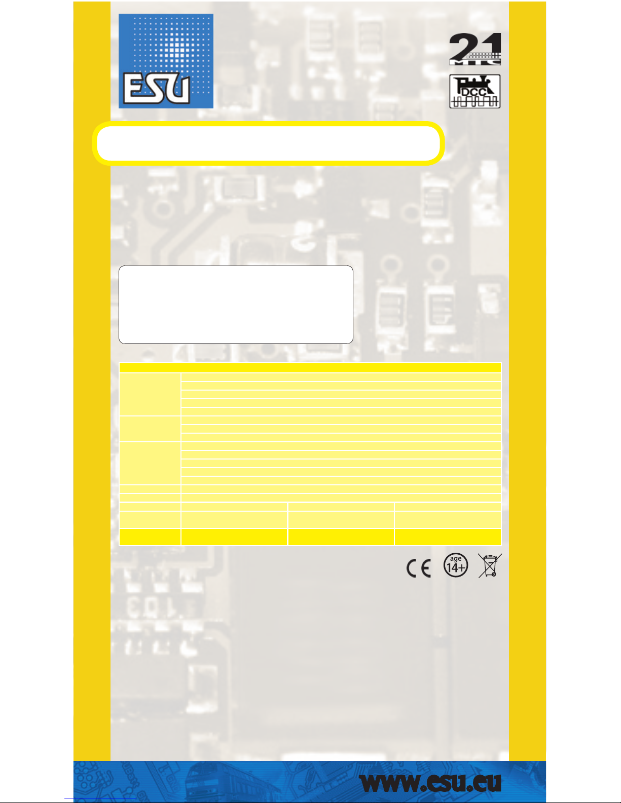
Abb. 2: LokPilot Standard with 21MTC interface
n.c. 1
n.c. 2
n.c. 3
AUX4 4
n.c. 5
n.c. 6
Rear light 7
Head light 8
n.c. 9
n.c. 10
Index pin 11
22 Right track
21 Left track
20 GND
19 Right motor
18 Left motor
17 n.c.
16 Common (+)
15 AUX1
14 AUX2
13 AUX3
12 VCC
How to connect the decoder:
Insert the decoder with
connector towards top
(e.g. Atlas, Intermountain, Bowser, Märklin®)
Insert the decoder with
connector towards
bottom (e.g. Brawa®)
Locomotive PCB
(Side view)
Locomotive PCB
(Side view)
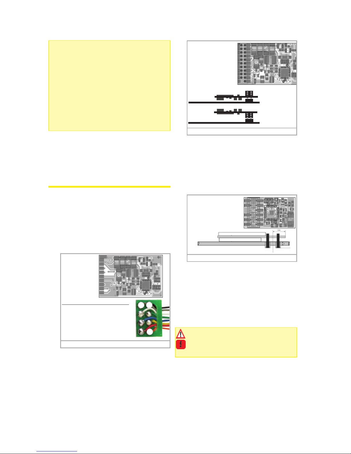
Locomotives with PluX12 interface
The LokPilot Standard supplied with a PluX12 interface (fig. 3) ist designed for locomotives in gauge TT.
Decoders fitted with PluX12 connector also will fit
into locomotives with PluX16 or PluX22 interface.
Consider the correct seating of the decoder: One
position of the multi-pin plug of the decoder has no
pin (index pin). This position should be marked in the
locomotive.
Abb. 3: LokPilot Standard with PluX12 interface
Head light 7
Common (+) 9
Index pin 11
Rear light 13
- 15
- 17
8 Motor +
10 Motor 12 Right track
14 Left track
16 AUX1
18 AUX2
Locomotives without interface
Firstly, please cut all wires installed in the locomotive.
Take special care to remove any connections to the
chassis (ground): the motor leads must be positively
potential-free, in other words they may not have any
contact to the chassis or body or the wheels and
wheel contacts. Figure 4 shows all connections.
Function outputs
You can wire all kind of load to the function outputs.
Please make sure that the load does not exceed
the permitted maximum current and there are no
short circuits. The outputs of the LokPilot have protection but if an external voltage is applied, the
outputs may suffer damage or destruction.
Only install bulbs rated 16V or higher and with a nominal current draw, that does not exceed 50 mA or
use suitable smoke generators such as Seuthe No.
11. If you like to use LEDs, a resistor with a rating
between 470 Ohms and 2.2 kOhms need to be wired in series. Running the LED without resistor will
lead to their immediate destruction!
Only the decoders with 21MTC interface have two
additional outputs besides the 4 standard outputs,
namely AUX3 and AUX4. Since they are pure „logicoutputs“, it is not possible to connect any external
loads directly. External power transistors are required. Connect AUX3 and AUX4 via the 21MTC interface; there are equal to the other outputs. ESU offers
an appropriate adapater board (art.no. 51968) with
transistors.
Locomotives with 21MTC interface
Some LokPilot Standard decoders are equipped with
an 21MTC interface (fig. 2) You can insert the decoder in two ways: either the pins are put through the
decoder; the socket of the decoder remains visible
after installation (mounting on top) or the decoder
is inserted in such a way that the pins go straight
into the socket. Once the decoder sits in the socket,
the socket is hidden from view. Which of the two
mounting positions is the correct one depends solely
on the locomotive. The position of the marker-pin is
the crucial indicator. Plug the decoder into the socket
in such a way that the locomotive interface corresponds with the decoder. Do not apply too much
pressure when inserting the plug. The decoder must
go in without force.
 Loading...