

Page 1

En g i n E E r i n g Ed i t i o n
Instruction manual
1. Edition, September 2014
Class 66/77
Page 2
2
Content
1. Declaration of Conformity
We, ESU electronic solutions ulm GmbH & Co. KG, Edisonallee 29, D-89231 Neu-Ulm, Germany, declare in sole responsibility that the product
„ESU H0-Diesellok Class 66/77“, part number: 31050, 31051, 31052, 31053, 31054, 31055, 31056, 31057, 31058, 31059, 31070, 31071,
31072, 31073, 31074, 31075, 31076, 31077, 31078, 31079 complies with all relevant regulations of the Directive for Electromagnetic Com-
patibility (2004/108/EG). The following harmonised standards have been applied:
EN 55014-1:2006 + A1:2009: Electromagnetic Compatibility - requirements for household appliances, electric tools, and similar apparatus - Part
1: Emission - Product
EN 55014-2:1997 + A1:2001 + A2:2008: Electromagnetic Compatibility - Requirements for household appliances, electric tools, and similar
apparatus - Part 2: Immunity - Product family standard.
1. Declaration of Conformity ........................................2
2. Prototype .................................................................3
3. Model .....................................................................6
3.1. Important remarks - please read this first ......... 6
3.2. Unpacking the model ...................................... 6
3.2.2. Mounting & removing the centre pick-up ..... 6
3.3. Outward appearance and special features ........ 7
4. The technology of the ESU model ............................8
4.1. Possible operating modes of the class 66/77 .... 8
4.1.1. Analogue mode ........................................... 8
4.1.2. Digital mode ................................................. 8
4.1.2.1. Digital operation with DCC systems .......... 8
4.1.2.2. DCC with RailComPlus®............................ 9
4.1.2.3. Prerequisites for RailCom® Plus ................. 9
4.1.2.4. M4 registration .......................................... 9
4.1.2.5. Digital operation with Märklin® Digital...... 9
4.2. Your first ride................................................... 9
4.2.1. Lighting functions ......................................... 9
4.2.2. Sound functions ......................................... 10
4.2.3. Curve and turnout sensors.......................... 10
4.2.4. Synchronised smoke generator ................... 10
4.2.4.1. Filling the smoke generator holding tank . 10
4.2.4.2. Operating the smoke generator ............... 11
4.2.5. PowerPack energy storage .......................... 11
5. Decoder Settings (Programming) ............................12
5.1. Configuration Variables (CVs) ........................ 12
5.1.1. Standardisation in the NMRA ...................... 12
5.1.2. Bits and Bytes ............................................. 12
5.2. Programming the decoder ............................. 12
5.2.1. Programming with DCC systems ................. 12
5.2.2. Programming with Märklin® 6021 ............ 12
5.2.2.1. Changing to the programming mode ...... 13
5.2.2.2. Short mode ............................................. 13
5.2.2.3. Long mode .............................................. 13
5.2.3. Programming with the Märklin® Central
Station®............................................................... 13
5.2.4. Programming with ESU LokProgrammer ..... 14
5.3. Adress settings .............................................. 14
5.3.1. Short Addresses in DCC mode .................... 14
5.3.2. Long Addresses in DCC mode .................... 14
5.3.3. Motorola® address ..................................... 14
5.3.3.1 Consecutive addresses for more functions 14
5.4. Adapting the Driving Characteristics .............. 15
5.4.1. Acceleration and Deceleration .................... 15
5.4.1.1. Shunting mode ........................................ 15
5.4.2. Starting Voltage, Vmax ............................... 15
5.5. Break sectors ................................................. 15
5.5.1. DC break mode .......................................... 15
5.5.2. Märklin® brake mode ................................ 15
5.5.3. Lenz® ABC brake mode ............................. 16
5.6. Adjusting the volume .................................... 16
5.6.1. Overall sound volume ................................. 16
5.6.2. Adjust individual sounds ............................. 16
5.6.3. Motor sound .............................................. 16
5.6.4. Auxiliary sounds ......................................... 16
5.7. PowerPack ..................................................... 16
5.8. Decoder reset ................................................ 17
5.9. Adjusting the brightness of the lights ............ 17
5.10. Smoke generator ....................................... 17
5.10.1. Blower of the smoke generator ............... 17
5.10.2. Heating temperature ............................... 17
6. Maintenance..........................................................17
6.1. Removing the housing ................................... 17
6.2. Lubrication .................................................... 17
6.3. Replacing wheel sets ..................................... 17
6.4. Replacing traction tires .................................. 18
6.5. Installing a coupler ........................................ 18
7. Accessories supplied with the model ......................20
8. Technical support ...................................................20
9. Spare parts ............................................................20
10. List of all important CVs .......................................21
12. Warranty Certificate .............................................23
Page 3

3
En g i n E E r i n g Ed i t i o n
Original
Prototype
2. Prototype
With the liberalisation of the international rail goods
traffic established in 2001 the newly founded rail
operators needed to procure motive power in order
to be able to handle the traffic they had fought so
hard to take away from the state owned railways.
The procurement of technically sophisticated new
vehicles was often not possible due to budgetary
restraints. A more cost effective solution was offered by the American Electro Motive Division (EMD)
with the class 666 that had already been tested and
proven in Great Britain. The locomotives known as
the JT 42 CWR are based on the American SD40
and ongoing development culminating in the SD
40-2, which were found to be most reliable due to
their simple, but proven design.
The first railway institution employing the diesel
electric class 66 on German lines was the Harbour
and Freight Services AG in Cologne the so called
Häfen und Güterverkehr Köln AG (HGK). In 1999
this company purchased two units. Almost at the
same time the class 66 was introduced to other European countries. Rail traffic corporations having
purchased or leased class 66 locomotives can be
found in France, Belgium, the Netherlands, Luxembourg and Norway. So far about 650 units have
been delivered in two different version to European
customers. The somewhat long and slim outline
Class 66‘ predecessor is named JT 26 CW-66. The picture shows Deutsche Bahn 259 003 in Sed-
din on 28.9.1997
Picture: Rolf Wiemann
meets the clearance diagram of British Rail. The
square-edged design of the body and the chassis
with its massive boogies and quite a number of seemingly confusing pipes and cables give the class 66
an unmistakable appearance.
The General Motors twelve Cylinder Two Stroke
engine 12N-710G3B-EC can not only be heard but
also recognised due to its characteristic sound and
offers a power of 3194 HP (2350 kW). The starting
tractive effort amounts to 409 kN, the continuous
tractive effort is 260 kN. With a maximum speed of
120 km/h the class 66 locomotives can easily keep
pace with other trains using electric traction even
on mainlines. Due to the independence from centenary the client can, if need be, pick up the train
from the most remote spur or siding and take it
via DB mainlines right through to his own factory.
With their livery the class 66 locomotives form a
pleasant contrast to the standardized red livery of
the DB AG.
Since 1999 the HGK mainly handles block trains
with their class 66 locomotives albeit with varying
loads. Tank cars have been a standard load for HGK
class 66 locomotives taking the train over the entire
route to Braunschweig, Ingolstadt, Marktredwitz
and Aichstetten. But one can also find the locomo-
Page 4
4
Prototype
tives from Cologne in central Germany whenever
they haul a train to Leuna or Berlin, amongst others.
We have chosen the DE671 built in 2003 and with
an extended concession issued in 2011 as the prototype for our model that bears white stripes on
the front.
The livery of the class 66 locomotives is accentuated
by the sharp contrast of black or grey sides with
the light green contrast patches leading around the
cabs. In Germany, Belgium and the Netherlands the
Captrain locomotives are mainly deployed hauling
container traffic, block trains consisting of tank
wagons or coal cars. They also display their power
ahead of block trains made up of cars with sliding
sides carrying parts for the automotive industry. In
Germany these six axle locomotives regularly travel
from the Rhine Ruhr region as far as Berlin.
As from 2010 CB rail, a renter of locomotives sent
their German and Luxembourg subsidiaries under
the name of Ascendos Rail Leasing GmbH into the
game of rail freight traffic. For operations on only
partly electrified lines Ascendos has a stable of 20
class 66 locomotives and an extra three class 77.
For Modeltrain enthusiasts these locomotives with
their green livery accentuated by the turquoise and
yellow contrast stripes are highly attractive since
they are not only deployed to haul block trains with
containers, tank cars, construction materials, coal,
motor vehicles or machine parts but make themselves useful in track maintenance service of for
transfers of other vehicles. Particularly in the area
of construction site logistics these locomotives are
often seen with only a handful of cars. Well known
companies renting these six axle locomotives have
been and are the HGK, Crossrail, ITL or the Ruhrtalbahn deploying them all over Germany, Belgium
and the Netherlands.
The four units owned by the SNCF Benelux and regularly travelled through Belgium, the Netherlands
and Germany in their impressive and very elegant
blue silver livery. Initially it was quite easy to differentiate them due to their different design of the
contrast areas on the front and rear. They were
mainly hauling two axle hoppers, container trains
and tank car trains.
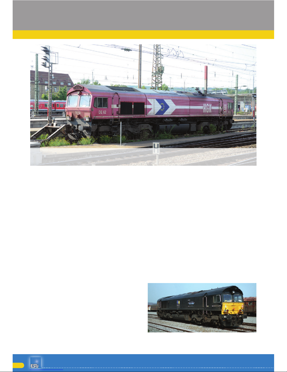
HKG‘s DE 62 still owns the british style headlights with outer position lamp in contrast to DE
61. Picture taken on 24.08.2011 in Ulm Hbf
Picture: Jochen Frickel
The prototype of the ESU model in Montzen
/ Belgium
Picture: Rolf Wiemann
Page 5

5
En g i n E E r i n g Ed i t i o n
Original
Prototype
Section view of class 77 showing the components locationsFigure 1:
Drawing: ESU GmbH & Co. KG
DE61 of HGK is allowed to be used in ger-
many only
Picture: Jochen Frickel
Crossrail‘s class 77 DE 6311 in Neuwied train
station
Picture: Rolf Wiemann
Page 6
6
Model
3. Model
3.1. Important remarks - please read this first
Congratulations to your purchase of the H0 diesel
locomotive class 66/77. Your H0 model offers various innovative functions. This manual provides a
step by step insight into the features of the class
66/77. Therefore we have one request:
Please read this manual prior to operating the model carefully. Although the model is quite robust,
inappropriate handling could lead to injury of the
operator or to damage of the locomotive. Do not
indulge in “costly” experiments.
This locomotive is not a toy and should only be •
operated under supervision.
Please make sure that the room has adequate •
ventilation when operating the smoke generator continuously!
Keep the smoke distillate away from children. It •
contains substances that may damage your health if consumed. In case of contact with your
eyes consult a doctor immediately.
Please return the pipette only into the packaging •
after you have emptied it completely. Otherwise
you may risk draining the smoke distillate.
Protect the model against wet conditions and •
humidity.
When working on the locomotive (maintenance) •
always make sure there is no power connected
to the model. Replace the housing on the chassis prior to operating the locomotive after maintenance work.
Make sure that no wires are squeezed or that no •
short circuit may occur.
Please note: All models shown here are pre-production samples. They may vary slightly from the series
production models!
3.2. Unpacking the model
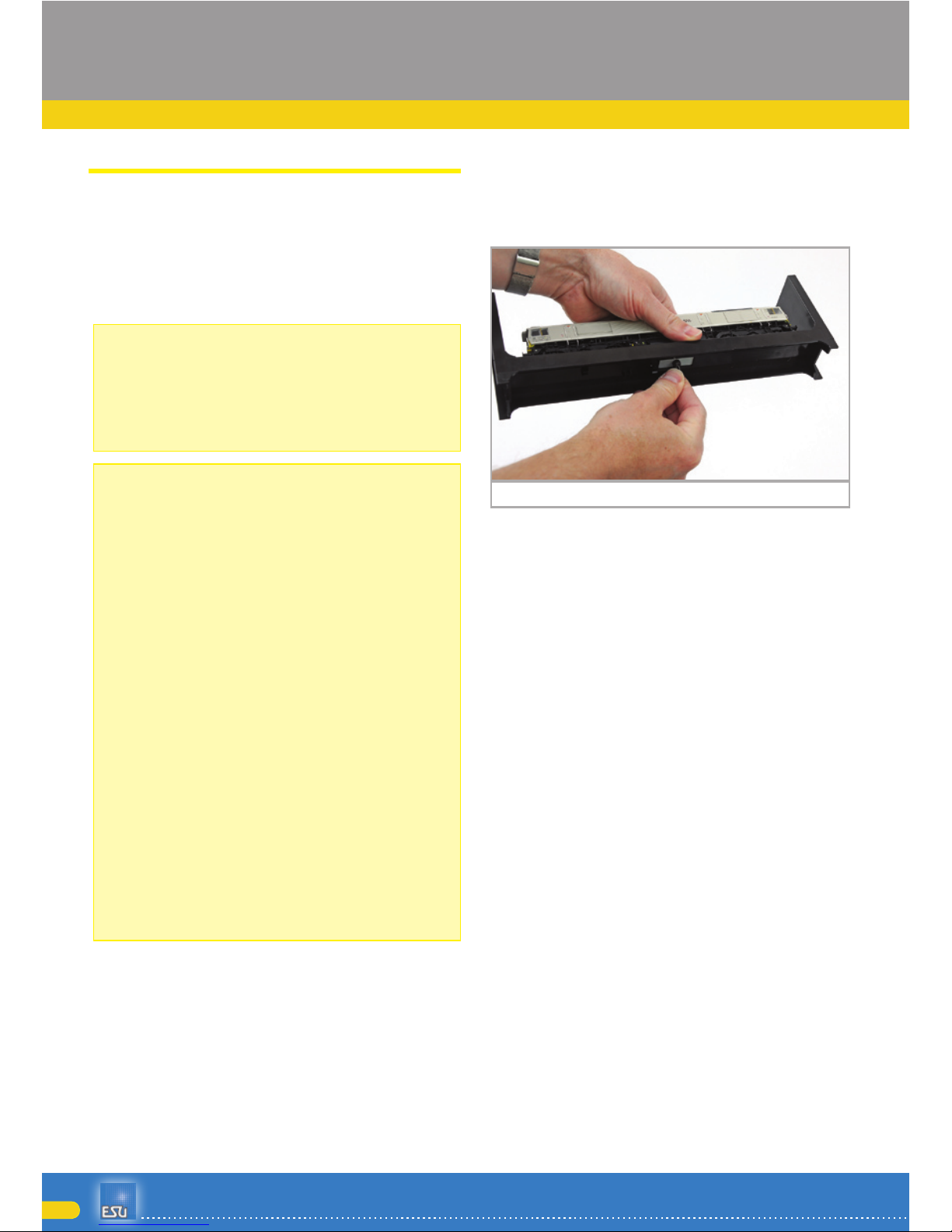
Pull the model screwed to the plastic holder with
both hands out of the foam insert. At the bottom of
the plastic holder you will find a hexagon spanner.
Now place the model on its side, hold the model
and the plastic holder with one hand and release
the hexagon bolt with the other hand.
For safe keeping of the spanner there are two retaining clips at the bottom of the plastic holder.
Please keep all parts of the packaging and this
manual for later use. Only the original packaging
guarantees proper protection against transport damage. Please fix the locomotive by means of the
hexagonal bolt to the plastic holder and place it into
the foam insert and put it into the carton and the
transport box prior to shipment.
Now you must adapt your class 66/77 to the control
mode of your layout. If you are a Märklin model
train enthusiast and therefore need a locomotive
with a centre pick-up you may simply place the locomotive onto the track, enter address 3 and you
are ready to run.
The centre pick-up clipped onto the locomotive serves not only for current pick-up but also activates
the electrical connection of both rails. Thus all 12
wheels pick-up current from the tracks.
If you operate a two-rail layout you must remove
the centre pick-up. How you do this is described in
chapter 3.2.2.
3.2.2. Mounting & removing the centre pick-up
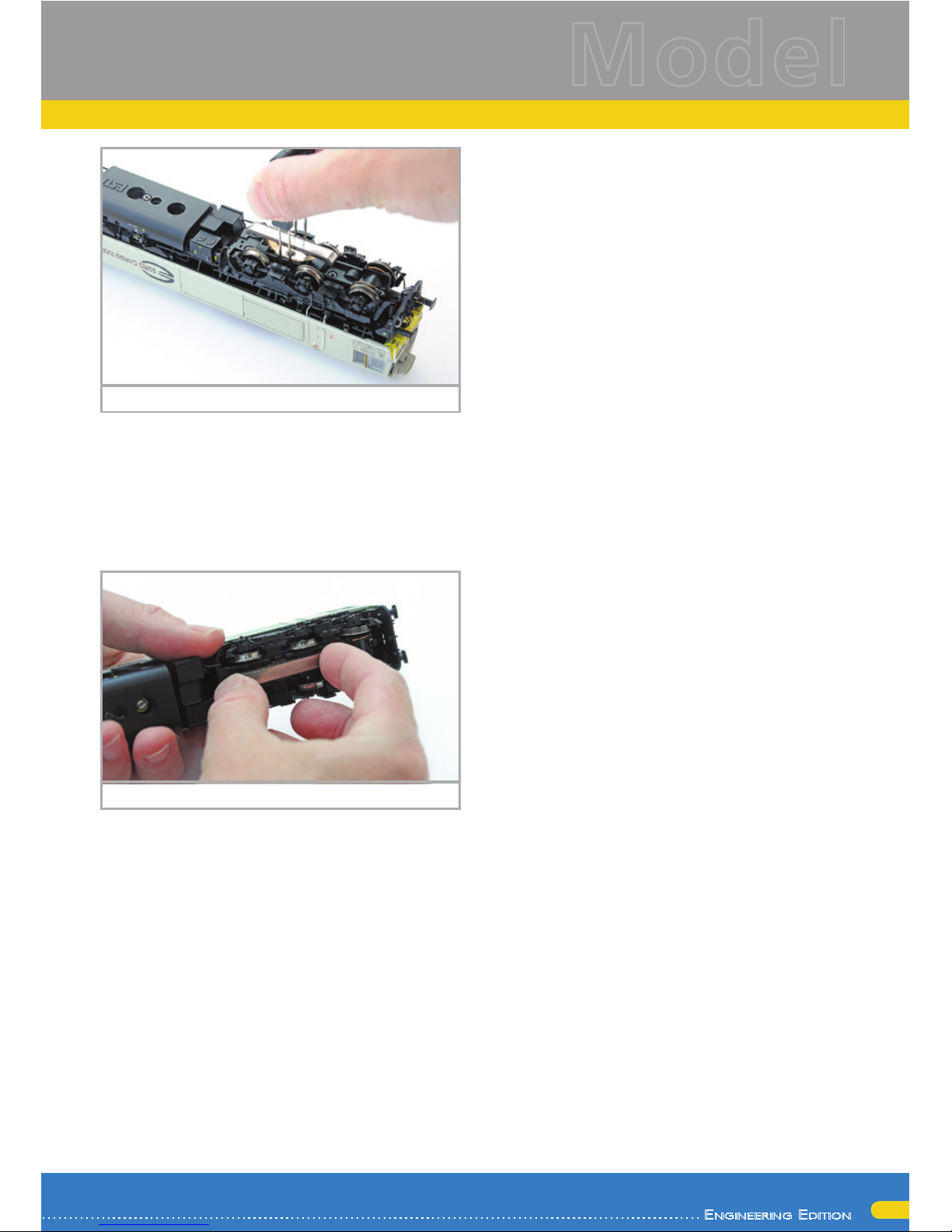
Removal: Put the locomotive on its roof. Then you
apply the tool in such a way that the ends of the
four wire brackets fit into the four holes below the
base plate of the centre pick-up. Carefully(!) squeeze the tool and then lever the centre pick-up with a
slight tug from its position.
release of hexagon boltFigure 2:
Page 7
7
En g i n E E r i n g Ed i t i o n
Model
Model
Mounting: For re-converting your locomotive to a
three-rail vehicle again hold the centre pick-up between thumb and index finger and place it in the
receptacle. Please note that the centre pick-up must
be attached to bogie “1”. Finally press the centre
pick-up until there is an audible “click”. That´s it!
3.3. Outward appearance and special features of
your class 66/77
With your new class 66/77 you can operate your
model trains prototypically like never before. There
are many separately applied detail parts on the metal housing as well as on the metal chassis. Of course, such details and modifications of the housing
are correct for the respective locomotive number.
All grab irons are made off sturdy plastic and are
separately applied. Separate plastic pipes are attached to the bogies.
The large speaker powered by the LokSound V4.0
M4 decoder distributes its powerful sound through
the cut-through radiator grills. New is also the sen-
sor triggering the squealing noise in curves and on
turnouts.
The ESU 5-pole high performance motor with a virtually silent commutator and two flywheels assure
plenty of power and smooth running. All four axles
are powered.
Four traction tires assure considerable tractive effort. Model train enthusiasts who prefer to run their
locomotives without traction tires and rather enjoy
more prototypical wheels sets find a voucher for six
wheel sets (2-rail system) with RP 25 wheels (please
also refer to page 26!). In order to obtain these
wheel sets, simply send this voucher to ESU. In order to assure perfect driving dynamics and excellent
sound without interruptions due to dirty tracks the
locomotive is equipped with a “PowerPack“energy
storage module.
A coupler shaft as per NEM 362 with short coupler
kinematics provides close coupling between locomotive and train in any situation.
In terms of its lighting the class 66/77 is just as
prototypically versatile as its full scale counterpart.
Of course there is directional lighting generated by
warm white LEDs that can be turned off at one end,
wherever the train is coupled to the locomotive.
During shunting all three headlights at either end
are switched on. In addition there is directional cab
lighting as well as illuminated driver’s cab-control
panel. Since these locomotives are employed internationally one can also set the lighting according to
the Belgian, Dutch and French lighting rules.
pickup shoe removalFigure 3:
Assembly of pickup shoeFigure 4:
Page 8

8
Technical functions
4. The technology of the ESU model
The new LokSound V4.0 M4 decoder is a central
part of your new class 66/77. Its circuitry is responsible for design and control of all running and sound
functions of the class 66/77:•
Driving forward and in reverse •
Lighting functions•
Sound functions•
Smoke generator•
Besides M4 the LokSound V4.0 M4 also supports
DCC with RailComPlus, Motorola® and Selectrix®
and also be operated on analogue layouts. Programming can be done either with DCC command
stations or with Märklin® central units, etc. the decoder automatically detects the mode of operation;
therefore you do not have to set anything in this
regard.
In case you wish to change any of the default settings of the locomotive (such as the address or the
sound volume) we recommend to first reading
chapter 5. This chapter lists all parameters of the
LokSound V4.0 M4 decoder and how to change
them with the various command stations available
on the market.
4.1. Possible operating modes of the class 66/77
4.1.1. Analogue mode
The class 66/77 may also be operated on conventional (=analogue) DC or AC model train layouts.
The number of available functions is, however, quite limited:
Driving forward and backwards•
Directional lighting•
Engine sounds (automatic)•
The smoke generator cannot be turned on in analogue mode. The engine sound sets in at about
6.5 V track voltage. At 8.5 V the locomotive slowly starts moving. Both DC transformers (throttles,
e.g.: ROCO®) and AC transformers (e.g.: Märklin®,
Titan) are suitable for analogue operation. Please
note, that due to the large number of different systems on the market you may not achieve troublefree operation with electronic throttles employing
PWM (pulse width modulation).
Attention: the class 66/77 must have come to a
complete standstill before you activate the changeof-direction command! Never switch to the opposite direction while the locomotive is moving.
4.1.2. Digital mode
For prototypical operation we recommend using
a digital command control system. The numerous
functions are only available in digital mode.
The default address (ex works) is “03” (DCC and
Märklin® Motorola®)
14 speed steps with Märklin® Motorola®.
In DCC mode the decoder automatically detects the
speed steps set in the command station.
4.1.2.1. Digital operation with DCC systems
The class 66/77 can be operated with any DCC
compliant system. Sounds and other functions of
the class 66/77 can be triggered with the function
buttons F0 through F21.
Function mapping (ex works):
Functionmapping:
Button
Function
F0 Directional lighting
F1 Engine sound
F2 Horn (high)
F3 Smoke generator
F4 Cab lighting
F5 Headlights off at cab 1
F6 Headlights off at cab 2
F7
Headlights as per lighting rules in BE/FR (Third headlight off)
F8 shunting lights DE/FR/BE
F9 Horn (low)
F10 Emergency stop
F11 Platform announcement
F12 Turnout sensor off
F13 Coupler sound
F14 Illuminated driver’s cab-control panel
F15 Shunting lights as per NL
F16
Air compressor / exterior lights as per CNet,TGOJ, CLF
F17 Station announcement
F18 Short horn (high)
F19 Short horn (low)
F20 Sanding
F21 Shunting mode
Page 9
9
En g i n E E r i n g Ed i t i o n
Model
Technical functions
The number of the functions actually available is determined by your command station respectively by
your throttle. Depending on the digital system there
may be fewer functions available.
4.1.2.2. DCC with RailComPlus®
The LokSound V4.0 M4 supports RailComPlus®,
which was jointly developed by Lenz® and ESU.
This means that the decoder automatically reports to RailComPlus® capable command stations.
You will never ever have to change a locomotive
address manually! Simply put the locomotive onto
the track.
4.1.2.2. Prerequisites for RailCom® Plus
RailComPlus® implies an accordingly equipped digital command station. The ESU ECoS command
station supports RailComPlus®-capable decoders
from software 3.4. You don´t need to change anything about the decoder settings. It will be automatically recognised.
Of course you can change the locomotive name,
all functional key and locomotive symbols and after
that write it back on your decoder. This happens
automatically in the background.
If you do not wish to have the automatic recognition, you can switch it off by deleting CV 28, bit 7.
4.1.2.4. M4 registration
If you use a Märklin® systems Central Station®,
Central Station 2 or mobile station®
The locomotive will be automatically detected and
registered by the system once you have put it onto
the track. This process occurs completely automatically, you do not have to adjust any settings.
DCC with RailComPlus® has the highest priority
when registering the locomotive. Therefore the decoder will always register with RailComPlus® and
DCC on an ESU ECoS command station even when
M4 is active. If RailComPlus® is not available then
M4 will be treated as the second priority. Therefore the decoder will register with M4 on a Märklin
Central Station®.
Whenever you run your class 66/77 with a Märklin® central unit under M4, then the system limits
the number of available functions to 16.
4.1.2.5. Digital operation with Märklin® Digital (6021)
You may operate the class 66/77 with the Märklin®
6021 central unit without any problems. A special
feature allows you to assign three more addresses
besides the “actual locomotive address”. They are
known as following addresses. This enables you to
access 16 functions with your 6021. Details on how
to do this are described in chapter 5.3.3.1
4.2. Your first ride
Most certainly you wish to test your new locomotive right away. We recommend going about this
step by step. Put the locomotive onto the track call
it up on your handheld throttle.
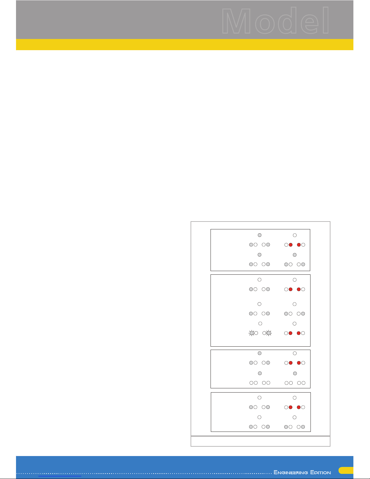
4.2.1. Lighting functions
First turn on the lights by pressing F0. Then the white forward headlights as well as the red rear lights
of the class 66/77 should light up. If you wish you
Beleuchtung Class 66/77
vorne hinten
Deutschland
Fahren
Rangieren
Belgien
Fahren
Rangieren
Nothalt:
Abwechselndes
Blinken der
weißen unteren
Lichter vorne
Niederlande
Fahren
Rangieren
Frankreich
Fahren
Rangieren
Lighting functionsFigure 5:
Page 10

10
Technical functions
may switch on the cab lighting with F4 in order to
better see the cab interior.
If you now press F7 (while the headlights are turned
on) then the illuminated driver’s cab-control panel
will come to life. You will clearly see this through
the side windows of the cab.
It is common practice to turn of the head and tail
lights at the cab where a train is coupled to the
locomotive. Press F5 is the train coupled to cab 1
in order to switch off the head (tail) lights at that
end. When shunting without any vehicle coupled to
the locomotive you should press F8 in order to have
prototypical lighting for shunting.
In each bogie there are 4 LEDs, which are activated
during braking and thus simulate the sparks of the
brake shoes on the wheel rim as can be observed
on locomotives hauling heavy trains.
4.2.2. Sound functions
After pressing F1 (preliminary lubrication and starting sequence) your class 66/77 comes to life and
continues with the typical sound of an idling two
stroke engine.
Once you go to speed step 1 the prime mover will
rev up before the locomotive slowly starts moving.
The response of the prime mover to different throttle settings is for both - acceleration and slowing
down - somewhat delayed compared to dieselhydraulic locomotives, as is the case with the prototype. Shortly before coming to a standstill you will
hear the squealing brakes.
Of course you may trigger various user sounds with
your throttle (refer to the table on page 8). You may
also adjust the volume of each individual sound sequence. How to do this is described in chapter 5.6.
Another special feature is the station announcements in different languages to suit different countries. Simply write the following values in the CV
mentioned below:
CV Value Language: station announcement
48 0 German
48 1 Dutch
48 2 French
4.2.3. Curve and turnout sensors
The class 66/77 has been equipped with a comprehensive set of sensors in order to reproduce prototypical sounds in curves and across turnouts.
Please take note of the following:
These sensors function only when the locomotive is
travelling at low speed. As soon as the locomotive
stops or drives faster than speed step 7 (of 28) the
squealing in curves and over turnouts will not be
replayed.
The curve and turnout sounds will only be active
if the engine sound is turned on. The curve sensor
works for radii of about 80 cm. The sensors may
not detect very large radii. Unfortunately certain
mechanical limits are unavoidable.
The contact brackets for the turnout sensors are located below the axles 1 and 6 (in other words, the
outer axles). Also refer to Fig. 11 on page 18. These
brackets should not be pushed or bent manually!
Treat these brackets with great care.
Occasionally there may be some sparks at the contact brackets when traversing a turnout. The curve sensors have been tested with all commonly
available DC and AC systems. While traversing a
turnout the bogies may be raised slightly.
If you do not wish to hear any sounds in curves or
on turnouts you can switch off this function with
function button F12.
4.2.4. Synchronised smoke generator
The class 66/77 is equipped with a load dependent, synchronised smoke generator that can be
controlled with your command station respectively
handheld throttle. The system consists of a holding
tank for the smoke distillate, an evaporator unit
with temperature control and a blower thatch exhausts the smoke in a controlled manner.
This system can adjust both the amount and the intensity of the smoke discharged subject to the operating conditions and thus assures prototypical performance. This system has been especially tuned for
the class 66/77 and also comprehensively tested.
Please bear in mind the following remarks in order
to assure safe operation:
Only use the ESU smoke distillate part
N0. 51990. Other liquids may lead to
damage of the paint finish, choking the
system or a faulty heating unit due to
unwanted deposits. Only activate the
smoke generator while observing the
model and in a well ventilated room.
4.2.4.1. Filling the smoke generator holding tank
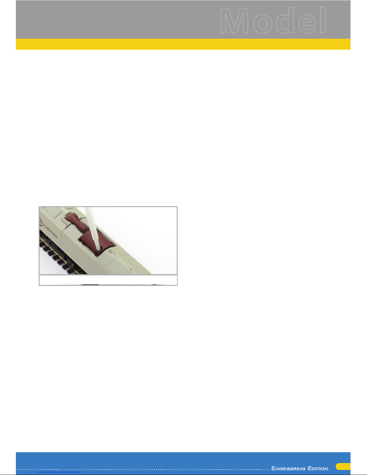
First take the pipette from the packaging of the
model and pull about 0.4 to 0.5 ml smoke distillate
Page 11
11
En g i n E E r i n g Ed i t i o n
Model
Technical functions
into it. Please observe the index markers on the
pipette in order to establish the appropriate quantity. Then carefully inject the distillate into the large
opening of the red-brown silencer.
Do not exceed the maximum quantity of the holding tank of 0.5 ml. If in doubt rather put less liquid
into the system! Due to the integral temperature
sensor the smoke generator will not be damaged
even if there is no liquid in the system!
Fill the smoke system only while the locomotive is
on a horizontal sector but never on a gradient. Do
not turn the locomotive with liquid in the tank sideways or upside down! This avoids the drainage
of the distillate.
4.2.4.2. Operating the smoke generator
The smoke generator only works in conjunction
with the sound. Smoke without sound is not possible.
First activate the smoke generator with the function
button F3. As long as the engine (prime mover) is
not running nothing happens just like with the prototype. After pressing F1 you will hear the sounds
of the starter motor. As soon as the prime mover
is firing acoustically the diesel locomotive blows a
strong cloud of smoke from the exhaust into the
“model sky”. Like with the prototype the intensity
of the smoke from the exhaust is reduced as soon
as the prime mover begins to idle.
More intense smoke will be emitted during acceleration and, of course, there is no smoke when the
locomotive slows down.
In order to protect the model the smoke generator
is turned off automatically after 6 minutes. Thus
overheating is avoided in case there is no distillate
in the holding tank. Switch off the F3 button and
then on again in order to reactivate the smoke
function.
The maximum capacity of the holding tank is 0.5
ml and is sufficient for about 10 to 15 minutes operation.
In some instances it may happen that the system is
clogged up due to an excessive amount of distillate
in the holding tank. Simply blow some air through
the exhaust opening in order to remove the drops
of condensation.
The smoke generator system as well as the entire
locomotive gets quite warm. Let the model cool
down before putting it back into its packaging.
You may adjust the amount and the intensity of
smoke as you desire. You find more information on
how to do this in chapter 5.10.
4.2.5. PowerPack energy storage
The class 66/77 is equipped with a maintenance
free “PowerPack” energy storage module. This facilitates uninterrupted power supply even on dirty
tracks. The PowerPack is only active in digital mode.
In analogue mode it will be automatically switched
off.
After turning on the power supply the “Power
Pack” must first be charged. This may take up to 60
seconds. Only then the full capacity will be available. The system supplies power to the lighting, the
motor and the sound functions. The maximum time
that the system should cover can be set (also refer
to chapter 5.7.).
Filling the smoke unitFigure 6:
Page 12

12
Decoder settings
5. Decoder Settings (Programming)
Chapter 5 covers setting various parameters of the
LokSound decoder. Should you not be familiar with
the handling of CVs please take the time to read
these occasionally quite complex instructions.
After an introduction into the world of parameters
in chapter 5.1, we explain in the following section
5.2 how to change various parameters in DCC
mode and with Märklin® central units.
The chapters 9 to 16 explain which parameters
have what kind of influence on the behaviour of
the LokSound decoder.
5.1. Configuration Variables (CVs)
LokSound decoders follow the CV concept developed in the US. CV stands for „Configuration Variable“ and indicates that the storage cells described
above are not only variable but they also determine
the behaviour of the decoder.
5.1.1. Standardisation in the NMRA
The NMRA (National Model Railroad Association)
has defined which CVs determine certain parameters of a decoder. The DCC standard allocates fixed
numbers for certain CVs (adherence is obligatory).
This greatly simplifies things for the user since decoders of most manufacturers comply with this standard and therefore dealing with CVs requires the
same process with the same CV-numbers regardless
of the manufacturer.
The DCC concept permits to enter numbers ranging
from 0 to 255 into CVs. Each CV carries only one
number.
While the position number is predetermined, the
range of values may vary. Not all CVs must accept
values ranging from 0 to 255.
The permitted values for LokSound decoders are listed in the table in chapter 20.1. showing all available CVs.
5.1.2. Bits and Bytes
Most CVs contain numbers: CV 1 for instance
contains the locomotive address. This can be any
number between 1 and 127. While most CVs expect numbers to be entered, some others are rather
like a „collection point“ of various „switches“, that
administer different functions in one CV (mainly
„on“ or „off): CVs 29 and 49 are good examples:
you must calculate the value for these CVs yourself.
The value depends on which settings you want to
program:
Have a look at the explanations for CV 29 in the table in chapter 10: firstly, decide which options should
be active. The column „Value“ has two numbers
for each option. If the option is switched off, the
value is 0. Otherwise, it is a number between 1 and
128. Add all the values for the respective options to
arrive at the correct value for this CV.
Example: Let us assume you want to run trains with
the ECoS in DCC mode with 128 speed steps. Analogue detection should be active (because you also
want to drive your locomotive in analogue mode).
All other options are not active.
Therefore you must write the value 6 in CV 29 (0 +
2 + 4 +0 = 6).
5.2. Programming the decoder
In this paragraph we explain how you can program
the decoder with the most commonly available digital systems.
5.2.1. Programming with DCC systems
LokSound decoders support all NMRA programming modes as there are the programming track
modes (Direct Mode, Register Mode, Paged Mode)
and the mode for the main („POM“, „Programming on the Main“).
Programming on the Main enables you to program
your decoders comfortably without having to remove the locomotive form the layout. In this case, the
command station talks directly to the decoder by
using its locomotive address, for instance: „Locomotive number 50, write the value 7 into CV 3!“.
Thus knowing the locomotive address is a precondition. Unfortunately, you cannot read CV values.
However, with RailCom® you can read CV values
on the main. More on this topic in chapter 15.
Assuming you have a suitable DCC system you can
read CV values on the programming track. You can
also reprogram the locomotive address without
knowing the old address since the command station simply transmits the command „Write value 7
in CV 3!“. Each decoder receiving this command
will execute it.
ESU counts the bits from 0 to 7 as laid out in the
standards while others (e.g.: Lenz®) count the bits
from 1 to 8.
5.2.2. Programming with Märklin® 6021
The LokSound V4.0 M4 decoder can be programmed with all mfx® compatible central units directly
Page 13

13
En g i n E E r i n g Ed i t i o n
Model
Decoder settings
via the decoder menu. However, in some cases not
all decoder options can be accessed. This compromise is necessary in order to assure that all
mfx® central units on the market can be supported. Read the manual of your central unit in order
to find out how to program mfx® capable decoders. The procedure is identical to programming
Märklin® locomotives
5.2.2.1. Changing to the programming mode
Enter the programming mode with the 6020/6021:
The throttle must be set to „0“. No other locomotives may be on on the layout. Watch out for flashing
signals of the locomotive!
Press the „Stop“ and „Go“ buttons of the 6021 •
simultaneously until a reset has been triggered (alternately pull the mains plug of the transformer).
Press the „Stop“ button in order to switch off the
track voltage. Enter the current decoder address.
If you do not know the current address, simply
enter „80“.
Activate the change-of-direction button (turn the •
throttle knob to the left beyond the arrestor until
you hear a click sound), hold it in this position and
then press the „Go“ button.
Please bear in mind that the 6020/6021 only per-•
mits you to enter values from 1 to 80. The value 0
is missing. Always enter „80“ instead of „0”.
5.2.2.2. Short mode
The decoder is in the short mode (the headlights
flash periodically in brief intervals).
Now enter the number of the CV that you want to •
adjust e.g.: „01“. Always enter this number with
two digits.
For confirmation activate the change-of-direction •
routine (now the lights flash twice very quickly).
Now enter the new value for the desired CV, e.g.: •
15 (two digits).
For confirmation activate the change-of-direction •
routine (now the lights light up for about one second).
Then you can enter other CVs as desired.•
Selecting „80“ allows you to exit the programming
mode. Alternately you can switch off the track voltage and then on again (press the „Stop“ button on
the 6021, then the „Go“ button).
5.2.2.3. Long mode
You access the long mode by entering the value
07 in CV 07 while in the short mode. The decoder
confirms the change to the long mode by slowly
flashing lights.
Enter the hundred-digit and the ten-digit (decade) •
of the CV that you want to change. Example: If
you want to adjust CV 124, you enter „12“.
For confirmation activate the change-of-direction •
routine (now the lights flash periodically: long –
short – long – short - etc.)
Now enter the unit of the CV („04“ in this ex-•
ample).
For confirmation activate the change-of-direction •
routine. Now the decoder expects the entry of the
CV value. The lights flash periodically: long – short
– short).
Now enter the hundred-digit and the ten-digit •
(decade) of the new CV value (as a two-digit number). Example: You want to write the value 135.
Therefore, you enter „13“.
For confirmation activate the change-of-direction •
routine. Now the lights flash periodically: long –
short – short – short).
Now enter the unit of the new CV value as a two-•
digit number („05“ in this example).
For confirmation activate the change-of-direction •
routine (now the lights light up for about one second).
Now you can adjust more CVs in long mode.•
Exit the long mode by switching off the track vol-•
tage and then on again (press the „Stop“ button
on the 6021, then the „Go“ button).
5.2.3. Programming with the Märklin® Central-
Station®
With the Central Station® until software version
2.04, you can program the CVs 1 to 80 via the Motorola® programming menu. Unfortunately, you
can only enter values between 1 and 80. Find more
information regarding this programming mode in
chapter 8 of the manual of the Central Station®.
Owners of a Central Station “Reloaded” or a Central Station 2 can program LokSound decoders in
DCC mode without any problems. With the CS1
“Reloaded” please proceed as described in the manual in chapter 18 (“Decoder programming”).
When using a Central Station 2, DCC programming
is somewhat trickier.
Page 14

14
Decoder settings
Establish a new locomotive manually. This must be •
done even if the decoder registers itself via mfx®.
The locomotive address is not important in this
context.
Call up the new “Dummy” locomotive with a •
throttle.
Open the menu “Edit locomotive” and select type •
“DCC”.
Open the function “Edit locomotive”.•
Now enter all CVs you wish to configure in the •
list. Only then the command station will read out
the values and save any changes.
5.2.4. Programming with ESU LokProgrammer
The LokProgrammer 53451 offers the easiest and
most comfortable way of setting the CVs of LokSound decoders: simply by a few mouse clicks on
an MS-Windows® computer. The computer saves
you to look for the various CV numbers and values.
More information is contained in the manual for
the LokProgrammer.
You can access all properties of ESU decoders with
the LokProgrammer. Since this works independently
form the data format it also works for mfx® decoders.
Please use the software version from V4.3.0 onwards for the LokSound V4.0 decoder. The software
is available for download on our website!
5.3. Adress settings
Each LokSound decoder requires a definite address
to be addressable for the central unit. Depending
on the type of decoder and the digital system, there
are several possibilities how to allocate addresses.
5.3.1. Short Addresses in DCC mode
Normally you would control LokSound decoders
with the short address that is stored in CV 1. In DCC
mode, the permitted values range from 1 to 127. In
order to enable the decoder to „listen“ to the short
address you must delete bit 5 in CV 29.
Some digital systems (e.g. ROCO® Lokmaus II,
Lenz® digital plus, Lenz® compact) only support
the values 1 – 99 as short address.
5.3.2. Long Addresses in DCC mode
You can operate LokSound decoders also with long
addresses (4-digit addresses). The supported values
range from 128 – 10239. The long address is stored
in the CVs 17 and 18. You must activate the long
address by setting bit 5 in CV 29.
Bit 5 in CV 29 switches between short and long
address. The decoder can only respond to one
address at a time.
If you want to use your LokSound with the long
address it is practical to program this address directly with your digital system: most modern digital systems (e.g. ESU ECoS, Bachmann E-Z Command®
Dynamis®) have a menu for programming long
addresses. The command station not only programs
CV 29 correctly but also assures the correct storage
of the values for the long address in CV 17 and 18.
If you want to enter the long address manually in
CV 17 and 18 please refer to 5.2.2.3.
5.3.3. Motorola® address
You can also operate many LokSound decoders
with the Motorola® format. The address for this
operating mode is stored in CV 1.
This address is identical to the short address in DCC
mode as described in chapter 5.3.1. The LokSound
decoder responds both to commands in DCC and in
Motorola® mode at the same time.
Märklin® digital devices (6020, 6021, Delta®) can
only work with addresses from 1 to 80. Should you
have entered a higher value in CV 1 you will not
be able to drive this locomotive with these central
units.
5.3.3.1 Consecutive addresses for more functions
The extended Motorola®-Format covered only the
lighting function (F0) and the auxiliary function F1
to F4. Of course, this is far too few for the many
functions of the LokSound V4.0.
Therefore one can assign up to three additional
addresses (4 addresses in total). The so called consecutive addresses follow immediately after the
actual address stored in CV 1 and serve to trigger
functions. Motor control is solely accomplished via
the base address in CV 1.
Example: You select the address 50 in CV 1 for a
class 50 locomotive. You want to set 3 consecutive
addresses. They are 51, 52 and 53. They will then
switch the consecutive functions whenever you call
up theses addresses on your 6021:
Name Example Functions
Base address 66 F0, F1 – F4
Consecutive address 1 67 (66+1) F5 – F8
Consecutive address 2 68 (66+2) F9 – F12
Consecutive address 3 69 (66+3) F13 – F16
Page 15
15
En g i n E E r i n g Ed i t i o n
Model
Decoder settings
Please make sure that no other vehicle is programmed to any of the consecutive addresses (in this example 51 to 53). Otherwise you will inadvertently
run several vehicles at the same time!
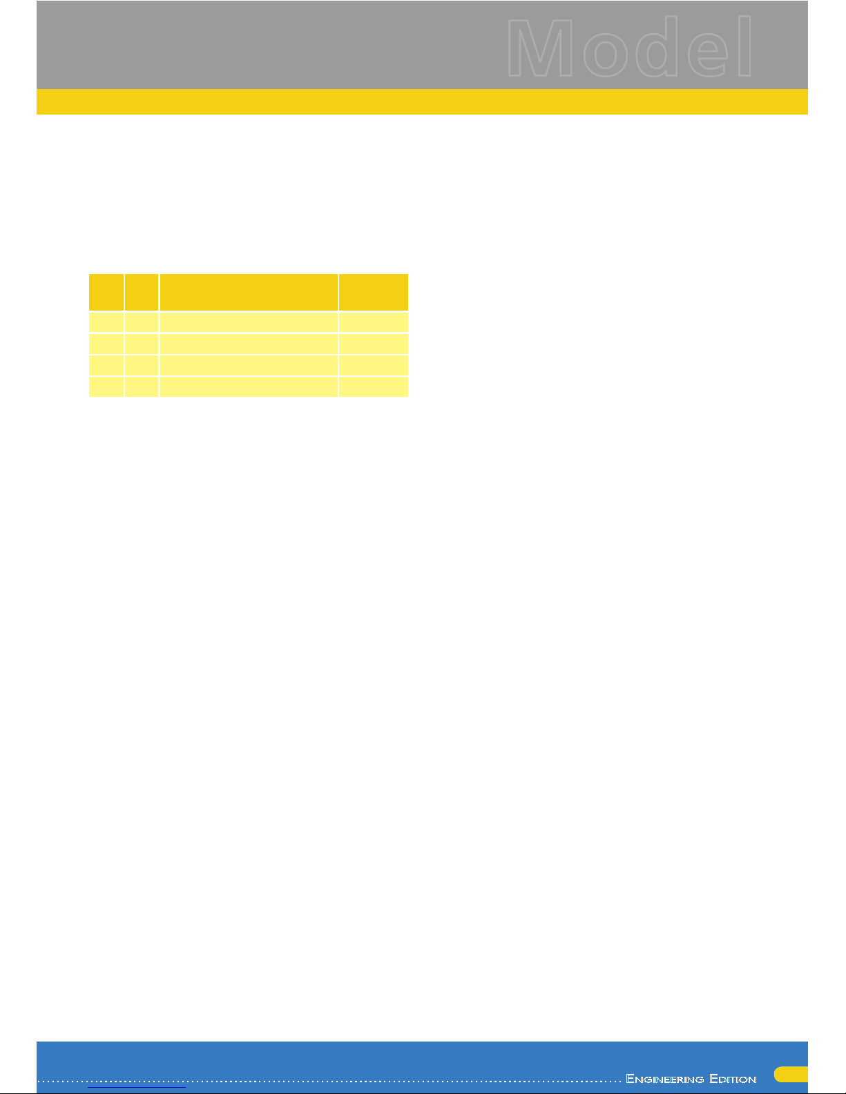
The consecutive addresses are activated with bits 3
and 7 in CV 49. For reasons of compatibility they
are not next to each other. The relationship is as
follows:
Bit 7 Bit 3 Description
Value to be
added to
CV 49
0 0 No consecutive address 0
0 1 Consecutive address 1 active 8
1 0 Consecutive address 2 active 128
1 1 Consecutive address 3 active 136
First read out the value in CV 49 (default value: CV
49 = 1) and the value shown in column 4. If, for
instance, you wish to activate 3 consecutive addresses then you must write the value 136 + 1 = 137
into CV 49. Consecutive addresses are only active in
Motorola® mode.
5.4. Adapting the Driving Characteristics
5.4.1. Acceleration and Deceleration
Acceleration and brake time can be set independently from each other. Therefore, you could for
instance program a short acceleration and a much
longer brake time.
The time for accelerating is adjusted in CV 3 while
deceleration is set in CV 4. Permitted values are 0
(no delay) to 255.
The times set in these CVs work speed dependant.
Therefore, the acceleration distance and the brake
distance are longer at high speeds. In other words,
the faster the locomotive moves, the longer is the
distance until it stops.
5.4.1.1. Shunting mode
The default setting for the shunting mode is F3. It
reduces the speed to about 50%. Thus, you have
smoother control of your locomotive in the lower
speed ranges, which is important for shunting, particularly in the 14-speed-step mode.
5.4.2. Starting Voltage, Vmax
LokSound decoders know internally 256 speed
steps. They can be adapted to the characteristic
of the locomotive and allocated to the actually
available speed steps (14, 28, or 128).
The NMRA defined two options to facilitate this:
Motor characteristic via CV 2, 5, and 6. Enter the
start voltage in CV 2 and the maximum speed in CV
5. CV 6 corresponds with the speed at a medium
speed step. Thus, you can define a “kink” in the
speed curve. This mode is active if bit 4 = 0 in CV
29.
The values of the start, mid and maximum speed
are dependent on each other. Selecting a mid speed
that is lower than the start speed or higher than the
maximum speed could lead to some erratic driving
performance. Therefore always adhere to the principle: start voltage < mid speed < maximum speed.
5.5. Break sectors
Brake sectors have the purpose to slow down the
locomotive independently from the commands
issued by the command station. Frequently, this
function serves for stopping a train in front of a red
signal. If a LokSound detects a brake command, it
will slow down with the programmed deceleration
and then stop. After this enforced stop, the locomotive will accelerate again as per the programmed
values in CV 3.
Depending on the type of digital system, there are
several options on how to influence the decoder so
that it stops the train.
5.5.1. DC break mode
In order to activate the DC brake mode you must
set bit 3 in CV 27. The LokSound decoder will start
brake once it moves from a digital sector into a DC
sector provided the brake mode is active and the
polarity of the track voltage does NOT match the
current direction of travel. The locomotive will stop
taking into account the programmed deceleration.
5.5.2. Märklin® brake mode
In principle, the Märklin® modules 72441 / 72442
apply a DC voltage to the track instead of the digital
signals. Provided bit 3 and bit 4 in CV 27 is set, then
LokSound decoders detect this voltage and will stop
the train (CV 27 = Value 24).
The signal generated by these modules looks the
same as DC from conventional DC-transformers.
The LokSound could possible misinterpret this and
switch to the analogue mode instead of brake.
If you wish to control the LokSound decoder with
DCC signals and keep your Märklin® brake sectors
then you should switch off the DC analogue mode
by deleting bit 1 in CV 50. The LokSound will stop
Page 16

16
Decoder settings
as desired.
5.5.3. Lenz® ABC brake mode
As a new function the LokSound V4.0 decoder
supports the ABC braking technique introduced by
Lenz®. In order to use this function a group of antiparallel diods will be be soldered to one half of the
track. The resulting fall of voltage generates an assymetrical DCC signal. LokSound decoders are able
to detect the potential difference between the left
and right half of the signal. If desired, the decoder
will be stopped.
To be able to use the ABC technique you also need,
beside the adequate LokSound V4.0 decoder, an
appropriate brake module. The ABC technique can
only be operated with boosters offering an exact
symmetrical output. All command stations and
boosters by ESU and Lenz® garantuee a symmetrical output. We don´t recommend to use other
boosters for the ABC technique.
If you wish to stop the LokSound decoder when •
the track signal is stronger on the right side than
on the left side (and the diods are also installed on
the left side), set bit 2 in CV 27.
If you wish to stop the LokSound decoder when •
the track signal is stronger on the left side than on
the right side (and the diods are also installed on
the right side), set bit 1 in CV 27.
If you want to stopp the decoder no matter in •
which half of the track the diods are set, please
set bit 2 and bit 1 in CV 27 (CV 27 = 3).
5.6. Adjusting the volume
The volume of all individual sounds of the class
66/77 can be independently adjusted. This enables
you to tune the model optimally according to your
preferences.
5.6.1. Overall sound volume
If you wish to reduce the overall volume simply enter a lower value in CXV 63 (master volume). All
sounds will be adapted in the correct ratio.
5.6.2. Adjust individual sounds
If you wish to adjust the volume of individual sounds
you must set the volume for each individual sound
by changing the value of its corresponding CV. In
order to enable the decoder to describe these CVs
correctly you must assure that the so-called “Index
CV” CV 32 has the correct value:
Before you change any volume CV please make
sure thatch CV 32 = 1.
The CVs for the sounds are defined as follows:
CV Function Value
259 Motor 128
275 Horn 128
299 Air compressor 128
307 Announcement #1 128
315 Coupler 128
323 Horn short (low) 128
339 Sanding 128
363 Announcement #2 128
371 Squeal in curves 128
379 Horn short (high) 128
403 Turnout “bump” 128
451 Chance 128
459 Brake 80
467 Shifting gears 128
5.6.3. Motor sound
Of course the sound of the prime mover can also be
adjusted individually.
5.6.4. Auxiliary sounds
Auxiliary sounds can also be adjusted individually. If
you wish not to hear a certain sound (for instance,
no sanding) then you set the corresponding CV to
the value of “0”.
5.7. PowerPack
The PowerPack energy storage module continues to
provide electric current to the decoder in case of a
power interruption. Should you have installed isolate track sectors ahead of signal where the sector
is disconnected form the power source if the signal
aspect shows “red”, the locomotive will still be powered by the “PowerPack” and will therefore continue running? Of course, in such a situation this may
be undesirable. Therefore it is possible to adjust the
buffer time in CV 113 as a multiple of 0.016384
seconds. The default value facilitates about 2.9 seconds. For smooth running the time should not be
Page 17
17
En g i n E E r i n g Ed i t i o n
Model
Decoder settings
set to any value lower than 0.3 seconds.
5.8. Decoder reset
You may reset the decoder to default values at any
time. Simply write the value 8 in CV 8.
Schreiben Sie dazu in die CV 08 den Wert 08.
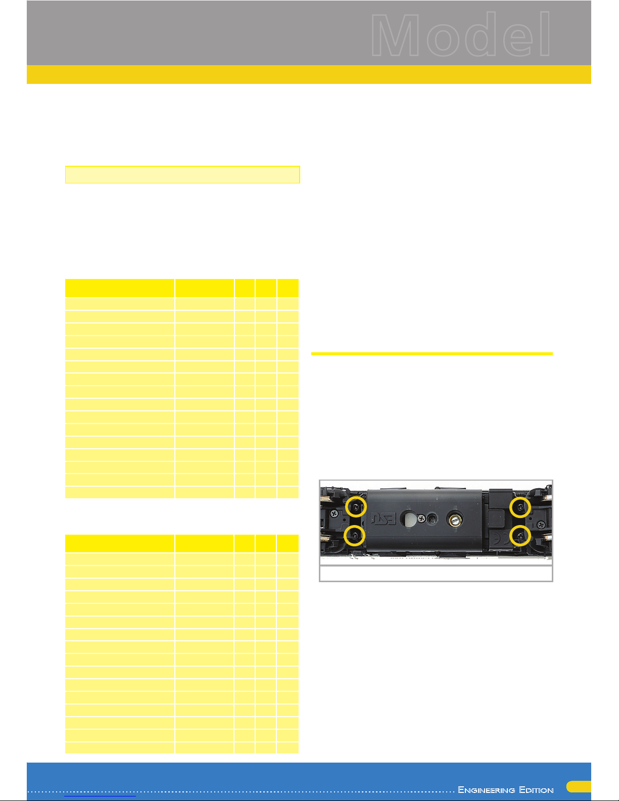
5.9. Adjusting the brightness of the lights
The brightness of all LEDs of the Class 66/77 can
be changed. The range is from value 31 (maximum
brightness, default value) down to the value 0
(lights are almost off, very dark).
Please change the following CV values:
Description
(* für CNet,TGOJ,CFL)
Decoder
output
Index
CV 32
CV Value
Lower right cab1
Light forward [1]
0 262 31
Lower right cab1 (blinking)
Light forward [2]
0 358 31
Lower right cab2 Light rear [1] 0 270 31
Lower right cab2 (blinking) Light rear [2] 0 366 31
Lower left cab1 AUX1[1] 0 278 31
Lower left cab1 (blinking) AUX1[2] 0 374 31
Lower left cab2 AUX2[1] 0 286 31
Lower left cab2 (blinking AUX2[2] 0 382 31
Upper cab1 AUX3 0 294 31
Upper cab2 AUX4 0 302 31
Interior lighting cab1 AUX5 0 310 31
Interior lighting cab2 AUX6 0 318 31
Red cab1 AUX7 0 326 31
Cab-control panel cab1 and 2 AUX8 0 334 31
Brake lights AUX9 0 342 15
Red cab2 AUX10 0 350 31
The value 0 in the following CV‘s will disable the
lights completely:
Description
(* für CNet,TGOJ,CFL)
Decoder
output
Index
CV 32
CV Value
Lower right cab1
Light forward [1]
0 259 1
Lower right cab1 (blinking)
Light forward [2]
0 355 12
Lower right cab2
Light rear [1] 0 267 1
Lower right cab2 (blinking)
Light rear [2] 0 363 12
Lower left cab1
AUX1[1] 0 275 1
Lower left cab1 (blinking)
AUX1[2] 0 371 1
Lower left cab2
AUX2[1] 0 283 1
Lower left cab2 (blinking)
AUX2[2] 0 379
Upper cab1
AUX3 0 291 1
Upper cab2
AUX4 0 299 1
Interior lighting cab1
AUX5 0 307 1
Interior lighting cab2
AUX6 0 315 1
Red cab1
AUX7 0 323 1
Cab-control panel cab1 and 2
AUX8 0 331 1
Brake lights
AUX9 0 339 3
Red cab2
AUX10 0 347 1
5.10. Smoke generator
You may also adjust the smoke generator as you
desire.
5.10.1. Blower of the smoke generator
The revs of the blower can be set with CV 138 (default value: 128). A higher value results in higher
revs and thus in more smoke. However, this also
means higher consumption of the distillate and a
somewhat “thinner” smoke plume.
5.10.2. Heating temperature
The temperature of the heating element can be adjusted with CV 139 (default value: 128). Only increase this value slightly in order to avoid excessive
wear and tear of the smoke generator. The settings
in CVs 138 and 139 are dependent of each other
and should be adjusted together.
6. Maintenance
6.1. Removing the housing
Put the model on its roof. You will find four Phillips
screws at the bottom of the chassis located between
the bogies and the fuel tank. Remove these screws
and put the model back on its wheels. Now you can
easily remove the housing. The yellow circles point
to the screws to be removed in order to take off the
housing.
6.2. Lubrication
We have equipped the class 66/77 with durable
mechanical components. All moving parts have
been permanently lubricated with durable grease
and oil. Additional lubrication of these individual
components is therefore not required.
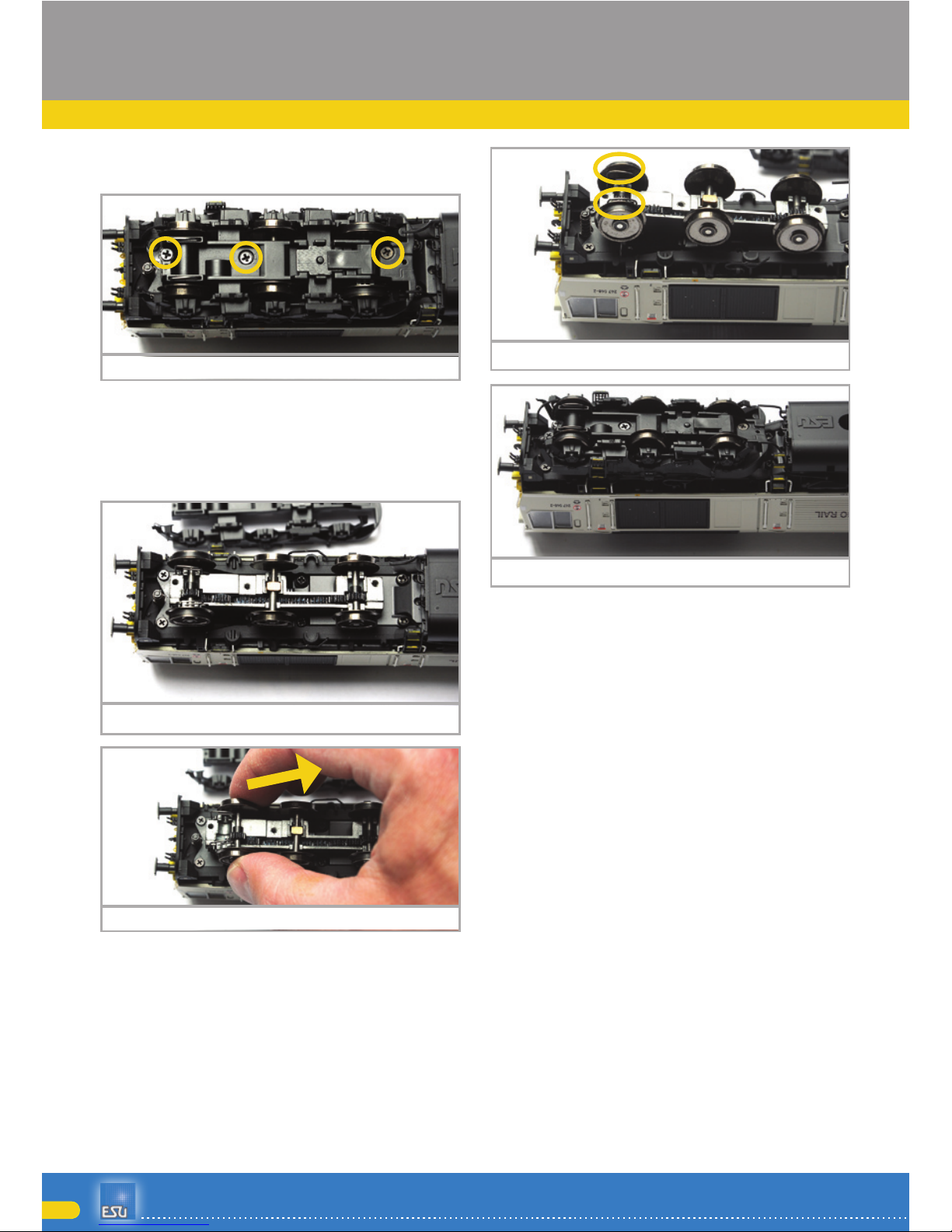
6.3. Replacing wheel sets
Exchanging wheel sets: If installed, first remove the
centre pick-up by pulling it off with the tool provided (also refer to chapter 3.2.2). Remove the three
Phillips screws at the bottom of the bogie (marked
Screw locationFigure 7:
Page 18
18
Maintenance
6.4. Replacing traction tires
Traction tires do age and must be replaced after
wearing. ESU supplies suitable traction tires with
each locomotive. For exchanging the traction tires
you must remove the side parts of the bogies (also
refer to chapter 6.3.).
Please make sure that the traction tires are put onto
the wheels uniformly and without any tension in
order to avoid out-of-round running characteristics
of the model. It has proven quite useful to place
the traction tires prior to mounting into some low
surface tension water (a drop of dishwashing liquid
is sufficient).
6.5. Installing a coupler
A standard coupler is mounted ex works at the cab
2 end of the locomotive. At the other end the deflector is closed and prototypical hoses have been
mounted. Installing a model train coupler takes
about two minutes. You will find the required parts
in the packaging. The only tool you may need is
either a pair of flat nose pliers or tweezers and a
thin screw driver.
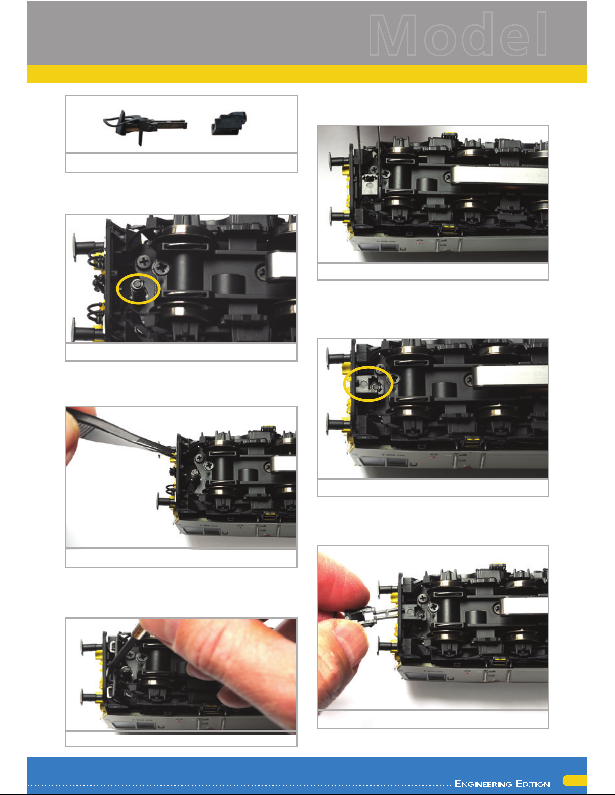
Remove the coupler shaft and the coupler from the
accessory bag.
Removal of bogie side partsFigure 9:
Installation of bogie side partsFigure 12:
Installed contract bracketsFigure 11:
Removal of wheel setFigure 10:
Screw location on bogieFigure 8:
with a yellow circle) and lift off the gear cover.
Remove the released bogie side part.
The contact bracket for the turnout sensor is located above the first and the sixth axle. These brackets remain in place when exchanging the wheel
sets. Slightly lift the wheel set and pull it towards
the centre of the locomotive.
Insert the new wheel set and make sure the current
pick-up strips touch the inside of the wheels.
When replacing and screwing down the bogie side
part please make sure that the contact brackets can
be seen through the elongated slots.
Page 19
19
En g i n E E r i n g Ed i t i o n
Model
Maintenance
The sprung socket for holding the coupler shaft is
located between front deflector and the front of
the bogie.
Pull off the hoses and the prototype coupler using
the tweezers or the flat nose pliers and then press
the deflector inwards.
Since the latter may sit quite firmly in its position
push a thin screw driver next to the retaining clip
between deflector and insert.
Accessory partsFigure 13:
Sprung socketFigure 14:
Removal of small partsFigure 15:
Place the coupler shaft onto the sprung socket that
the front faces left in “driving direction”.
Then press the shaft downwards and turn it by 90
degrees until it projects through the deflector at the
front.
Now insert the coupler.
Removal of deflectorFigure 16:
Installation of coupler shaftFigure 17:
Installed coupler shaft Figure 18:
Insert the couplerFigure 19:
Page 20
20
Maintenance
9. Spare parts
Due to the large number of parts built into class
66/77 we have divided the spare parts in to component groups. Some parts belonging to large parts
groups are also included in smaller groups.
Please bear in mind that only the spare parts listed in the supplied spare part list are available ex
works as spare parts. Enquiries for individual parts
are pointless.
Should you require a spare part you must first
identify the spare part group containing the needed part. For rarely needed parts you may have to
purchase a larger component group. You must state the listed ESU part number when ordering spare
parts from your hobby shop
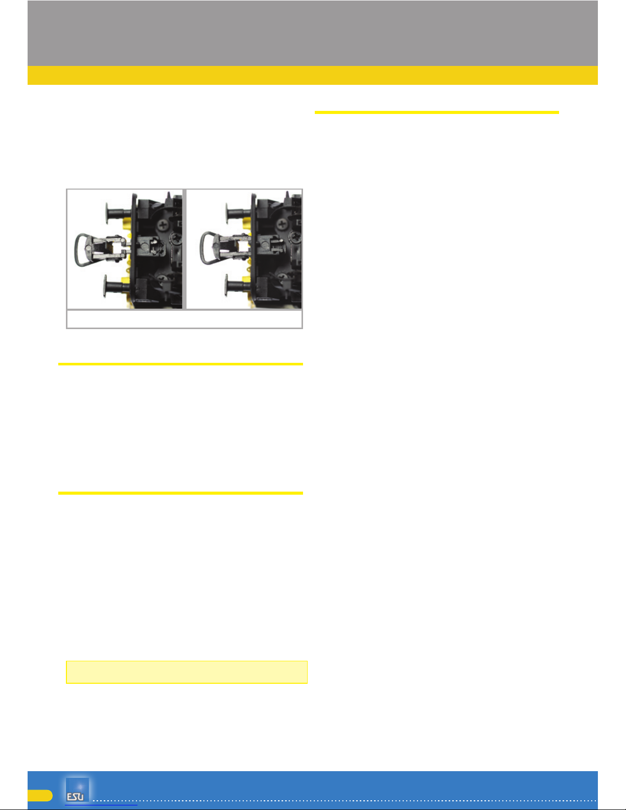
Both arresting positionsFigure 20:
The first arresting position of the coupler may be
needed in order to avoid the buffers of the locomotive and the first car missing each other in curves
(Particularly S curves) when ever heavy trains are
pushed through such curves. Generally you would
push the coupler into its proper position.
7. Accessories supplied with the model
ESU is fully aware of the “challenges” of model
train operations. Often enough small detail parts
break off and “disappear”. Since the class 66/77
has quite a few details and we want to make sure
that can enjoy your class 66/77 for a very long time
we have put a little plastic bag with small parts that
could easily break or get lost. Make sure you keep
these parts for the time when you may need them.
8. Technical support
Should you have questions regarding your class
66/77 to which you have not found the right answer in this manual please first contact your hobby
shop. The people there are your competent contact
for all questions relating to model trains.
Should you not be able to get an answer to your
question look up our homepage in the internet. We
continuously publish topical questions and answers
as well as the latest versions of manuals. Of course
you will also find our postal address as well as our
phone number on our site.
www.esu.eu
Page 21
21
En g i n E E r i n g Ed i t i o n
Model
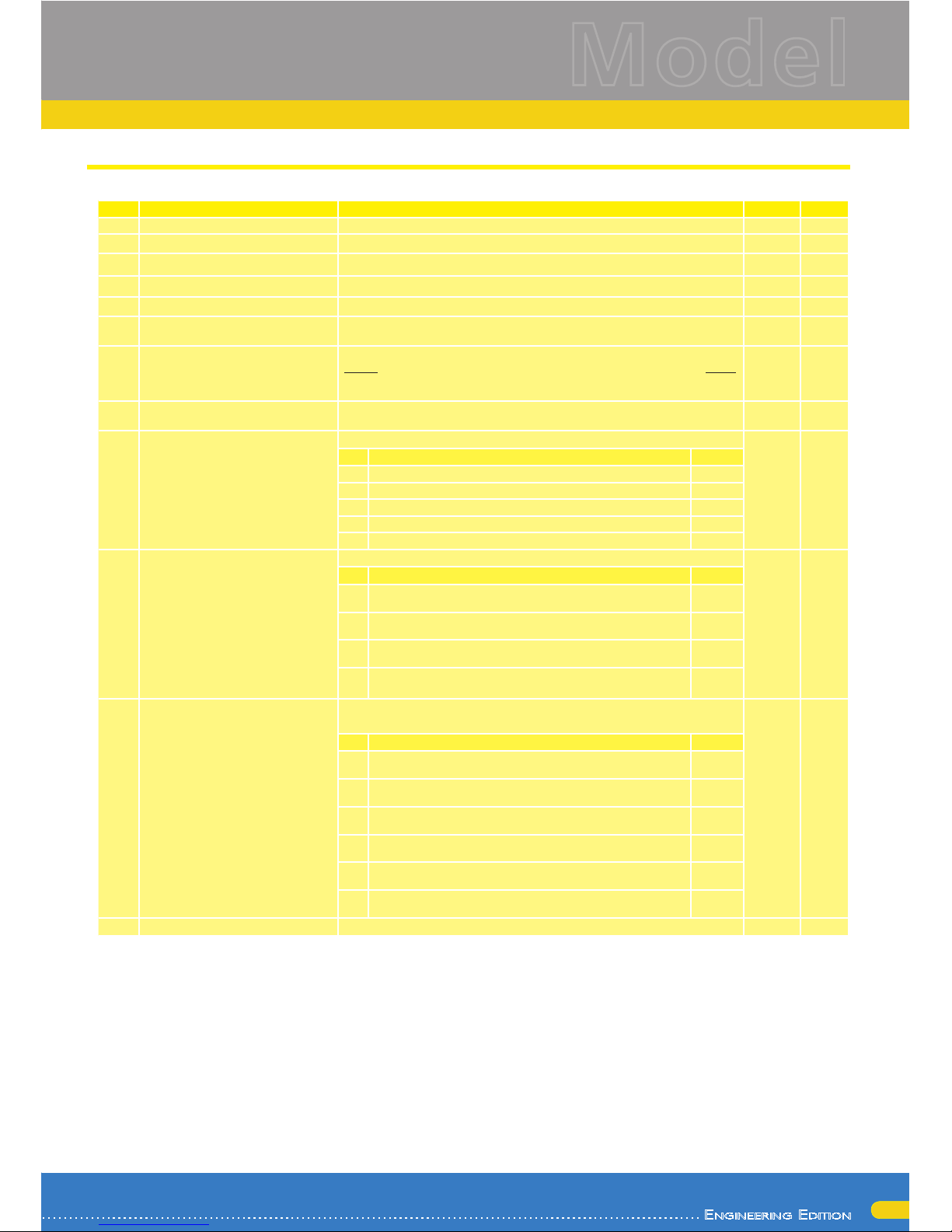
10. List of all important CVs
CV Name Description Range Value
1 Loco address Address of the loco 1 - 127 3
2 Start voltage Sets the minimum speed of the engine 1 - 75 3
3 Acceleration This value multiplied by 0.25 is the time from stop to maximum speed 0 - 255 65
4 Deceleration This value multiplied by 0.25 is the time from maximum speed to stop 0 - 255 45
5 Maximum speed Maximum speed of the engine 0 - 255 120
8 Manufacturer‘s ID Manufacturers‘s ID ESU - Writing value 8 in this CV triggers a reset to
factory default values
- 151
17 18Long address of the loco
Long address of engine
CV 17 contains the high byte (Bit 6 and 7 must always be enabled), CV18
contains the Lowbyte. Active only if enabled in CV 29 (see below)
128 9999
192
128
19 Consist Address Additional address for consist operation. Value 0 or 128 means: consist
address is disabled
0-255 0
27 Brake mode Allowed brake modes 24
Bit Function Value
0 ABC braking, voltage higher on the right-hand side 1
1 ABC braking, voltage higher on the left-hand side 2
2 ZIMO HLU brakes active 4
3 Brake on DC, if polarity against driving direction 8
4 Brake On DC, if polaritiy like driving direction 16
28 RailCom® Configuration Settings for RailCom® 131
Bit Function Value
0 Channel 1 Adress broadcast not enabled
Channel1 Adress broadcast enabled
0
1
1 Data transmission not allowed on Channel 2
Data transmission allowed on Channel 2
0
2
2 Command Acknowledgement on Channel 1 not allowed
Command Acknowledgement on Channel 1 allowed
0
4
7 RailComPlus® automatic loco recognition not active
RailComPlus® automatic loco recognition active
0
128
29 Configuration register This register contains important information, some of which are only
relevant for DCC operation.
30
Bit Function Value
0 Normal direction of travel
Reversed direction of travel
0
1
1 14 speed steps DCC
28 or 128 speed steps DCC
0
2
2 Disable analog operation
Enable analog operation
0
4
3 Disable RailCom®
Enable RailCom®
0
8
4 - 0
16
5 Short adresses (CV 1) in DCC mode
Long addresses (CV 17 + 18) in DCC mode
0
32
48 Language selection Selection of announcement languages for certain sound projects 0 - 255 0
Important CVs
Page 22

22
Important CVs
CV Name Description Range Value
49 Extended Configurations More important adjustments for the decoder 0 - 255 19
Bit Description Value
0 Enable Load control
Disable Load control
1
0
1 20 kHz motor pulse frequency
40 kHz motor pulse frequency
0
2
2 Disable Märklin® Delta® Mode
Enable Märklin® Delta® Mode
0
4
3 Consecutive addresses for Motorola® Protocol „low“-Bit 0
8
4 Disable automatic DCC speed step detection
Enable automatic DCC speed step detection
0
16
5 DisableLGB® function button mode
Enable LGB® function button mode
0
32
6 DisableZIMO® Manual Function
Enable ZIMO® Manual Function
0
64
7 Consecutive addresses for Motorola® Protocol „high“-Bit 0
128
50 Analogue mode Selection of allowed analogue modes 0 - 3 3
Bit Function Value
0 DisableAC Analogue Mode
Enable AC Analogue Mode
0
1
1 Disable DC Analogue Mode
Enable DC Analogue Mode
0
2
52 Load control parameter „K slow“ „K“-component of the internal PI-controller for lower speed steps 0 - 255 48
53 Control Reference voltage Defines the Back EMF voltage, which the motor should generate at
maximum speed. The higher the efficiency of the motor, the higher this
value may be set. If the engine does not reach maximum speed, reduce
this parameter.
0 - 255 140
54 Load control parameter „K“ „K“-component of the internal PI-controller.
Defines the effect of load control. The higher the value, the stronger the
effect of Back EMF control.
0 - 255 48
55 Load control parameter „I“ „I“-component of the internal PI-controller. Defines the momentum (iner-
tia) of the motor. The higher the momentum of the motor (large flywheel
or bigger motor diameter), the higher this value has to be set.
0 - 255 32
56 Operating range of load control 0 – 100 % Defines up to which speed in % load control will be active. A
value of 128 indicates that load control will be switched off after reaching
half speed.
0 - 255 255
63 Sound volume «Master» Master volume for all sounds 0 - 192 192
67-94Speed table Defines motor voltage for speed steps. The values „in between“ will be
interpolated.
0 - 255 -
113 Power Fail Bypass The time that the decoder bridges via the PowerPack after an interruption
of voltage. Unit: A multiple of 0.016384 sec.
0 - 255 100
125 Starting voltage Analogue DC 0 - 255 90
126 Maximum speed Analogue DC 0 - 255 130
127 Starting voltage Analogue AC 0 - 255 90
128 Maximum speed Analogue AC 0 - 255 130
138 Smoke generator - Blower Adjusting the fan speed. The higher the value, the faster operates the fan
and the more smoke will be ejected.
0 - 255 140
139 Smoke generator - Heating
temperature
Adaption of the heating temperature of the smoke generator. The bigger
the value, the higher the heating temperature.
0 - 255 160
253 Constant brake mode Determines the constant brake mode. Only active, if CV254 >0 0 - 255 0
Function
CV 253 = 0: Decoder stops linearly
CV 253 > 0: Decoder stops constantly linear
254 Constant braking distance forward A value > 0 determines the way of brake distance it adheres to, indepen-
dent from speed.
0 - 255 0
Page 23
23
En g i n E E r i n g Ed i t i o n
Model
12. Warranty Certificate
24 months warranty from date of purchase
Dear customer,
Congratulations on purchasing this ESU product. This quality product was manufactured applying the most
advanced production methods and processes and was subjected to stringent quality checks and tests.
Therefore ESU electronic solutions ulm GmbH & Co. KG grants you a warranty for the purchase of ESU
products that far exceeds the national warranty as governed by legislation in your country and beyond the
warranty from your authorised ESU dealer. ESU grants an extended
manufacturer‘s warranty of 24 months from date of purchase
Warranty
Page 24
24
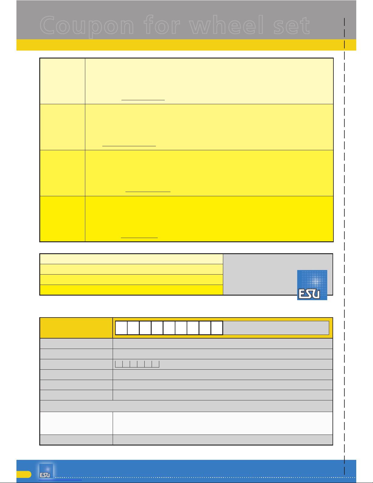
Coupon
DE
Kostenlose Zusendung von 6 Achsen mit Rp25-Rädern.
Sehr geehrter Kunde, bei Einsendung dieses Gutscheins erhalten Sie sechs Achsen, bestückt mit haftreifenlosen
Rädern mit niedrigem Rp25-Profil für noch bessere Optik Ihres Modells. Die Radsätze sind für den Betrieb auf Zweileitergleisen ausgelegt. Ein Betrieb auf Märklin®-Gleisen ist nicht vorgesehen.
Wir akzeptieren keine Photokopien dieses Gutscheins!
EN
Free delivery of six axles with Rp25 wheels.
Dear customer, by sending us this coupon you will receive 6 axles with a low Rp25-profile which are not equipped
with traction tyres to make your model look even better. These wheel sets are exclusively meant for being operated
on two-conductor tracks. An operation on Märklin® tracks is not intended.
We do not accept photocopies!
FR
Livraison gratuite 6 essieux avec un profil bas, selon Rp25.
Cher consommateur, si vous nous envoyez ce bon, vous recevrez 6 essieux avec un profil bas Rp25, sans bandages
d‘adhérence, pour que votre locomotive a l‘air encore mieux. Ces essieux doivent être utilisés seulement en 2-rail
(DC) et non en 3-rail (Märklin®).
Nous n‘acceptons pas les photocopies!
NL
Gratis levering van 6 wielassen Rp25.
Geachte klant, stuur ons deze bon en U ontvangt 6 wielassen met een laag Rp25 profiel, zonder rembandjes, opdat
uw locomotief er nog beter zou uitzien. Deze wielassen zijn uitsluitend te gebruiken bij een 2-rail systeem. Het
gebruikt ervan is niet bedoeld voor Märklin® rails.
Wij aanvaarden geen fotocopies!
[DE] Bitte senden Sie diesen Gutschein in einem frankierten Briefumschlag an:
Electronic solutions ulm
GmbH & Co. KG
Edisonallee 29
D - 89231 Neu-Ulm
(GERMANY)
[EN] Please put this coupon into a stamped envelope and send it directly to:
[FR] Veuillez svp insérer le bon dans une enveloppe affranchie et envoyez celui-ci à:
[NL] Steek aub de bon in een gefrankeerde omslag en stuur deze direct naar:
Absenderadresse (Bitte in Druckbuchstaben ausfüllen / Please fill out in capital letters)
ESU-Knd.Nr. [customer no.]:......
E
-
Bitte ausfüllen, falls bekannt oder vorhanden.
[If available./Indien beschikbaar./Si disponible.]
Name [Name]: .........................
Straße [Street]: ........................
PLZ [ZIP code] / Stadt [City]: .....
Land [Country]: .......................
E-Mail [Email]: .........................
Telefon [Phone]: ......................
Bitte um kostenlose Zusendung von 6 Achsen mit Rp25-Rädern [Please send me six axles with Rp25 wheels free of charge.]
Datum [Date]
Unterschrift [Signature]
û
Coupon for wheel set
u
Page 25

25
En g i n E E r i n g Ed i t i o n
Model
Warranty conditions:
This warranty is valid for all ESU products that have been purchased from an authorised dealer.
No claims will be accepted without proof of purchase. The filled in warranty certificate together with your
ESU dealer’s receipt serves as proof of purchase. We recommend keeping the warranty certificate together
with the receipt.
In case of claim please fill in the enclosed fault description as detailed and precise as possible and return it
with your faulty product.
Extend of warranty / exclusions:
This warranty covers free of charge repair or replacement of the faulty part, provided the failure is demonstrably due to faulty design, manufacturing, material or transport. Please use the appropriate postage stamps
when shipping the decoder to ESU. Any further claims are excluded.
The warranty expires:
1. In case of wear and tear due to normal use
2. In case of conversions of ESU - products with parts not approved by the manufacturer
3. In case of modifications of parts, particularly missing shrink sleeves, or wires directly extended on the
decoder.
4. In case of inappropriate use (different to the intended use as specified by the manufacturer).
5. If the instructions as laid down in the user manual by ESU electronic solutions ulm GmbH & Co. KG were
not adhere to.
Due to liability reasons any inspections or repairs can only be carried out on products that are not installed in
a locomotive or carriage. Any locomotive sent to ESU for inspection will be returned without even touching
it. There is no extension of the warranty period due to any repairs or replacements carried out by ESU.
You may submit your warranty claims either at your retailer or by shipping the product in question with the
warranty certificate, the receipt of purchase and fault description directly to ESU electronic solutions ulm
GmbH & Co. KG:
ESU GmbH & Co. KG
- Garantieabteilung Edisonallee 29
D-89231 Neu-Ulm
GERMANY
You will find further informations at our website: www.esu.eu
Warranty
Copyright 1998 - 2012 by ESU electronic solutions ulm GmbH & Co KG. Electrical characteristics and dimensions are subject to change without prior notice. All rights
reserved. ESU might not be held responsible for any damage or consequential loss or damage chaused by inappropriate use of the product, abnormal operating
conditions, unauthorized modifications to the products etc...
Not suitable for children under 14 years of age. Inappropriate use may result in injury due to sharp points and edges.
Märklin® and mfx® is a registered trademark of the company Gebr. Märklin® and Cie. GmbH, Göppingen, Germany. RailCom is a registered trademark of the
company Lenz Elektronik GmbH, Giessen, Germany.
All the other trade marks are owned by their respective right holders.
ESU electronic solutions ulm GmbH & Co. KG continues to develop the products according to the company´s politics. Therefore, ESU reserves the right to carry out
changes and improvements on the products listed in this manual at any time and without any advanced note.
Duplications and reproductions of this documentation are strictly forbidden and need to be allowed by ESU in writing.
Page 26

26
ESU P/N 04014-14980
 Loading...