

Esu 51801, 51820 Instruction Manual
Instruction Manual
4. Edition, December 2017
P/N 04213-13564
SwitchPilot V2.0
SwitchPilot Extension V1.0
SwitchPilot V2.0

2
1. Declaration of conformity ....................................... 3
2. WEEE delaration ....................................................... 4
3. Important notes – Please read this chapter first .. 4
4. How this manual will help you ............................... 5
5. Introduction – The SwitchPilot family .................... 5
5.1. Members of the SwitchPilot family ................................5
5.1.1. SwitchPilot overview ..................................................5
5.1.2. SwitchPilot V2.0 .........................................................5
5.1.3. SwitchPilot Extension .................................................6
5.2. Features .......................................................................6
5.2.1. Operational modes ....................................................6
5.2.1.1. k83 mode ...............................................................6
5.2.1.2. k84 mode ...............................................................6
5.2.1.3.User mode ..............................................................6
5.2.2. Transistor outputs ......................................................6
5.2.3. Servo outputs ............................................................7
5.2.3.1. Conventional servos ................................................7
5.2.3.2. Digital servos ..........................................................8
5.2.3.3. ESU servo motor .....................................................8
5.2.4. Feedback inputs .........................................................8
6. Connection to the digital system ........................... 8
6.1. Connecting elements of the SwitchPilot ........................8
6.2. Power supply from the digital system ............................9
6.3. Separate power supply.................................................9
6.4. Wiring of transistor outputs ........................................ 10
6.4.1. Connecting double-coil solenoids ............................10
6.4.2. Wiring daylight signals and light bulbs or LEDs ........10
6.5. Wiring a servo.............................................................11
6.6. Wiring feedback contacts ...........................................11
6.6. Wiring the SwitchPilot Extension ................................. 12
6.6.1. Relay outputs ...........................................................12
Contents
6.6.2. Wiring a motor drive ................................................ 12
6.6.3. LGB® motor drive ....................................................13
6.6.4. Polarizing electric frogs ...........................................13
7. Decoder settings (programming) ......................... 14
7.1. Changeable decoder settings ......................................14
7.1.1. Configuration Variables (CV) ....................................14
7.1.1.1. Standardization regarding NMRA .........................14
7.1.1.2. Bits und Bytes .......................................................14
7.2. Programming with DCC systems .................................15
7.2.1. Programming on the programming track .................15
7.2.1.2. Connecting to the programming track ..................15
7.2.2. Programming on the main track .............................16
7.3. Programming with Märklin® central stations .............16
7.4. Programming with the ESU LokProgrammer ...............16
8. Address settings ..................................................... 17
8.1. Turnout numbers .......................................................17
8.2. Decoder address .........................................................17
8.2.1. Schedule of turnout numbers and addresses ............17
8.3. Factory settings ..........................................................20
8.4. Programming addresses with programming button .....20
8.4.1. First address for outputs 1 – 4 ................................20
8.4.2. Second address for outputs 5 - 6 .............................20
9. Parameters of the transistor outputs ................... 20
9.1. Configuration of output with variable duration (k83) ..20
9.2. Output configuration to pulsed output....................................... 21
9.3. Configuration of an output for PECO solenoid drives ..21
9.4. Configuration for continuous operation (k84) .............21
9.5. Configuring the „zoom“-effect ..................................21
10. Features of servo outputs ................................... 21
10.1. Configuration of servo end position „A“ ..................21
10.2. Configuration of servo end position „B“ ...................21
10.3. Configuration of servo speed ....................................21
10.4. Disabling the pulse signal and power supply .............22

3
1. Declaration of conformity
We, ESU electronic solutions ulm GmbH & Co. KG, Edisonallee
29, D-89231 Neu-Ulm, Germany, declare in sole responsibility that
the product
Product description:
SwitchPilot, SwitchPilot Extension,
Part number: 51820, 51801
complies with all relevant regulations of the Directive for Electro-
magnetic Compatibility (2004/108/EG). The following harmonised
standards have been applied:
EN 55014-1:2006 + A1:2009: Electromagnetic Compatibility requirements for household appliances, electric tools, and similar
apparatus - Part 1: Emission - Product
EN 55014-2:1997 + A1:2001 + A2:2008: Electromagnetic Compatibility - Requirements for household appliances, electric tools,
and similar apparatus - Part 2: Immunity - Product family standard.
Copyright 1998 - 2017 by ESU electronic solutions ulm GmbH & Co KG. Electrical
characteristics and dimensions are subject to change without prior notice. All
rights reserved. ESU might not be held responsible for any damage or consequential loss or damage chaused by inappropriate use of the product, abnormal
operating conditions, unauthorized modifications to the products etc.
Not suitable for children under 14 years of age. Inappropriate use may result in
injury due to sharp points and edges.
Märklin® and mfx® is a registered trademark of the company Gebr. Märklin®
and Cie. GmbH, Göppingen, Germany. RailCom is a registered trademark of the
company Lenz Elektronik GmbH, Giessen, Germany.
All the other trade marks are owned by their respective right holders.
ESU electronic solutions ulm GmbH & Co. KG continues to develop the products
according to the company´s politics. Therefore, ESU reserves the right to carry out
changes and improvements on the products listed in this manual at any time and
without any advanced note.
Duplications and reproductions of this documentation are strictly forbidden and
need to be allowed by ESU in writing.
11. RailCom® ............................................................. 22
11.1. How to activate RailCom® ......................................22
11.2. How to read out CVs with RailCom® and ESU ECoS 22
11.3. Feedback of turnout position with the ECoS .............23
12. Options for SwitchPilot Extension ................... 24
12.1. Time of switching .....................................................24
12.2. Assignment of Relays ................................................24
13. Decoder reset ....................................................... 24
13.1. With DCC systems .................................................... 24
13.2. With programming button ........................................24
15.3. With ESU LokProgramer ............................................24
16. Support and assistance ....................................... 25
15. Technical data ....................................................... 26
15.1. Technical data SwitchPilot V2.0 .................................26
15.2. Technical data SwitchPilot Extension .........................26
20. List of all supported CVs...................................... 27
22. Warranty certificate ............................................. 31
4
3. Important notes – Please read this chapter first
We congratulate you on your purchase of an ESU Switch Pilot
decoder. This manual will guide you step by step through the features of the Decoder.
Important warning:
Please read this manual carefully. Although the SwitchPilot has
been designed as a robust device an incorrect connection may
lead to faults or even to the destruction of the device. Avoid any
“costly” experiments.
• The Switch Pilot is exclusively intended for use with model train
layouts only. It may only be operated with the components listed
here. Any other use is not permitted.
• Any wiring has to be carried out while power is disconnected.
• Any power supply must be protected by a fuse or circuit breaker
to avoid any potential hazards such as burning cables in case of
a short circuit. Only use transformers specifically designed for
model trains that bear the VDE/EN marks.
• Never operate the SwitchPilot unattended. The SwitchPilot is
not a (children’s) toy.
• Adhere to the wiring principles as outlined in this manual for
wiring any external components. Other circuitry may cause damage to the SwitchPilot.
• SwitchPilot is not water proof. It is not intended for outside use.
If you use this product for exterior applications you do so at
your own risk.
• Do not attempt to open your SwitchPilot module. Improper
treatment may cause damage or destruction.
Important notes
2. WEEE delaration
Disposal of obsolete electrical and electronic equipment (as practised in the European Union and other European countries with
dedicated collection systems).
This mark on the product, the packaging or the relevant documentation indicates that this product must
not be treated like household waste. Instead this
product should be disposed of at a suitable collection
point for recycling of electrical and electronic appliances. Thus you contribute to avoid negative impact on the environment and people’s health that could be caused by inappropriate
disposal. Recycling of materials contributes to preserve our natural
resources. For more information regarding recycling of this product, please contact your local administration, your waste collection service or the dealer / shop where you purchased this product.
5
4. How this manual will help you
This manual was divided into a few chapters, which will gradually
show you how to operate the SwitchPilot products.
Chapter 5 includes an overview of the features of the single
SwitchPilot decoders.
In chapter 6 we deal with the connection of your layout.
If you wish to adjust the factory settings of your decoder individu-
ally, just do so. In chapter 7 - 11, you will find detailed explanations
about which settings are possible and how you can change them.
Statements about technical data can be found in chapter 15 as
well as a list of all CVs assisted, if necessary.
By using the LokProgrammer, a new firmware file can be downloaded to the SwitchPilot any time.
5. Introduction – The SwitchPilot family
5.1. Members of the SwitchPilot family
The ESU SwitchPilot decoders are especially optimized for stationary operation on your layout. Not matter if you wish to activate
turnouts, signals, magnetic un-couplers, light bulbs and other
stationary loads or even if you prefer a „state of the art servo
motor: One of the SwitchPilot decoders will be quite useful for
you, for sure.
The SwitchPilot decoders can be supplied with power either from
the digital system or from an external DC-power source. Due to an
installed full bridge rectification and backup memory you can do
without any additional „power modules“.
All SwitchPilots are multi protocol capable and therefore can
either be operated with command stations as per the Märklin®Motorola® system (e.g.: 6021, Central Station®) or with DCC
compliant command stations.
SwitchPilot Decoders are able to control all current DCC programming modes and can be set up either on the main track or the
programming track. Thanks to RailCom® it is also possible to read
out data on the main track. Some of the SwitchPilot decoders can
be easily set up via a three-button, LED input unit.
By using the LokProgrammer, a new firmware file can be downloaded to the SwitchPilot any time.
SwitchPilot decoders are shipped in a robust body and stand out
due to their excellent price-performance ratio.
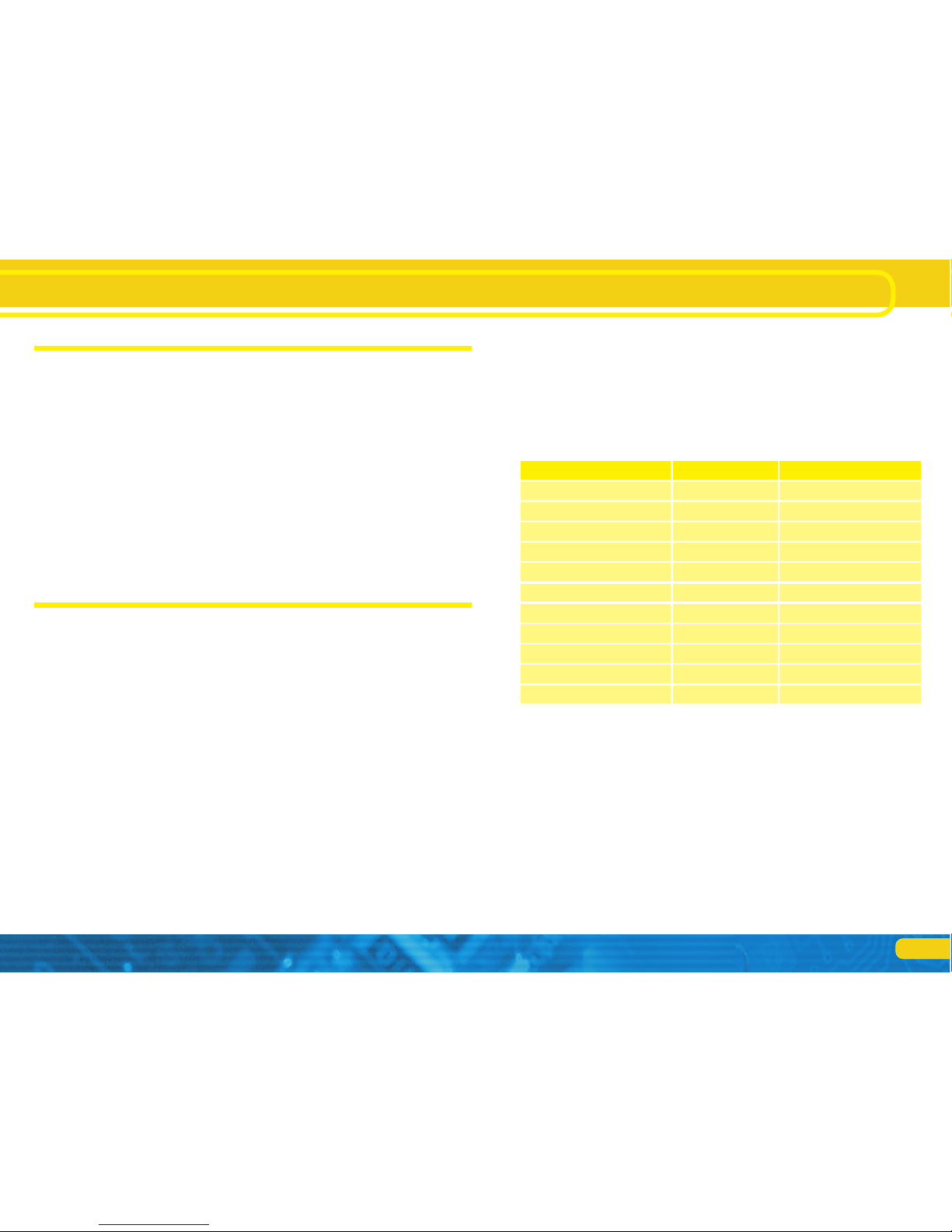
5.1.1. SwitchPilot overview
SwitchPilot V2.0 SwitchPilot Servo V2.0
DCC mode
Ok
Motorola mode
Ok Ok
DCC programming
Ok Ok
4 double transistor outputs
je 1,5A -
LED Monitor for outputs Ok -
2 servo outputs
Ok -
4 servo outputs
- Ok
Feedback input
Ok -
RailCom®
Ok Ok
Input unit
- Ok
Updatable Ok Ok
5.1.2. SwitchPilot V2.0
The SwitchPilot is a universal decoder for users who mainly have
double-solenoid motors installed, but would like to test the servo technology. Hence the SwitchPilot has four outputs (1-4) for
switching of up to 4 double-solenoid accessories (e.g. switches) or
8 accessories like uncouplers or light functions. Each output can
be programed individually for continuous or pulsed output with
variable pulse duration or blinking. Thus it is possible to connect
light bulbs or LEDs without any additional relays. Automatic fading
assures prototypical run-up and shut-down of signal lamps.
In addition two commercially available RC-servos for hobby applications may be wired directly to the SwitchPilot (outputs 5 – 6).
Their speed and end position can be adapted as required.
Introduction - The SwitchPilot family

6
The SwitchPilot Familie
The operating mode switch is only for the use with Motorola control units to enable compatibility with Marklin controllers. If the
SwitchPilot is used with the DCC protocol the operating mode
switch needs to stay at the middle position (factory default).
5.2.1.1. k83 mode
When you push the slide into the k83 position then the outputs
1 to 4 will be switched to pulse operation regardless of the programed settings. The SwitchPilot behaves exactly like a Märklin®
k83. Use this mode whenever you want to operate conventional
solenoid drives.
5.2.1.2. k84 mode
In the k84-mode the outputs 1 to 4 will be set to variable regardless of any pre-programed settings. The SwitchPilot behaves
exactly like a Märklin® k84. Use this mode to operate LEDs or light
bulbs and whenever you do not require any specific programming.
All consumer loads are directly electrified by the SwitchPilot. You
must not connect any external voltage!
5.2.1.3.User mode
The user mode is switched on by setting the switch for selecting
the operating mode into the centre position. Only in this mode the
outputs 1 to 4 will behave according to the software controlled
settings. This is the correct use to DCC format, k83 and k84-Modus are only meant for Motorola® command stations.
5.2.2. Transistor outputs
The SwitchPilot has a total of 8 transistor outputs that are grouped
in four pairs 1 to 4. Each pair has two outputs, OutA and OutB.
there are also two separate servo outputs.
The transistor outputs can be set to continuous, to pulsed power
or to alternating blinking.
If requested, the pulse signal can be disabled when the end position of the lever is reached. Furthermore, the power supply to
each servo can be interrupted to prevent any “twitching” of some
cheaper servos. Due to the integral DCC RailCom® - transmitter
it is possible to provide status feed back of the accessory to the
command station. For instance an ESU ECoS command station can
then display the manually activated change of status.
Of course the transistor outputs of SwitchPilot are electronically
protected against overload and short circuit.
5.1.3. SwitchPilot Extension
For operating motor drives for turnouts or for the polarization of
the frogs you require a relay with potential free contacts. For this
purpose each SwitchPilot can be connected to a SwitchPilot Extension which can be plugged into the side of the SwitchPilot and
receive its power from it.
Each SwitchPilot Extension module has 4 by 2 relay outputs that
are operated in parallel to the corresponding outputs of the
SwitchPilot. This corresponds to the established k84-solution.
5.2. Features
5.2.1. Operational modes
All SwitchPilots are multi protocol capable and therefore can
either be operated with command stations as per the Märklin®Motorola® system (e.g.: 6021, Central Station®) or with DCC
compliant command stations. For this SwitchPilot decoders must
be contacted with solenoid accessory addresses.
Therefore, operation with the Lokmaus 2 is not possible. The Lokmaus 2 does not send DCC commands to solenoid devices.
The SwitchPilot has a switch to select different operating modes.
Thus you can easily set the desired mode. Therefore “programming” is not necessary for most standard applications.
This switch only operates the four transistor output pairs 1 to 4.
The servo outputs are not affected.
7
Pulsed output:
If the output is set to pulse operation it will be activated as
soon as a command is received. At the same time a timer starts
counting: the “on-time” (duration of pulse) is determined by a
pre-programed value. The output cannot be active for longer or
shorter than this value. Should you let go of the button before
the end of the first pulse then the output remains active until the
pre-determined time has been reached. If you press the button
longer than the pre-determined pulse duration then the output is
switched off even though the button is still pressed.
The limitation of the pulse duration helps avoid damage to solenoids.
The pulse duration can be set in such a way that the outputs are
active as long as the button on the control panel is pressed. This
operating mode is compatible with Märklin® k83 decoders.
Variable:
Pressing the appropriate button on the control panel (e.g.: “red”
for Märklin® central units or „+“ for Lenz Digital Plus®) switches
on the first output OutA. It remains on until the corresponding
button for output OutB is activated. OutA and OutB work like a
change over switch.
Logically this operating mode complies with the Märklin® k84 decoder. From every output EITHER OutA OR OutB is active. Both
cannot be switched at the same time!
Alternating blinker:
In this mode the terminals OutA and OutB of an output will be
activated alternately. This is quite useful for the blinking red lights
at level crossings amongst others.
The “on-time” can be set in the same fashion as the pulse duration.
Subject to the pulse duration and also in continuous mode it may
happen that several outputs are on at the same time. Please note
that the total current of all connected loads must not exceed the
total permitted load of the decoder, namely 3.0 A.
5.2.3. Servo outputs
RC-servos can be connected to the SwitchPilot decoders. Compared to gear motors, servos are intelligent actuators with integrated intelligence which can move to the self-desired position and
can also hold this state.In doing so, they force a different angle
and speed. Will leverage against a force out, it controls the servo
with all force against the angle constantly striving it should have
to keep.
The nominal position will be set by a pulse line (orange on Graupner® servos, otherwise white). A constant voltage (4.8 V - 6V)
completes the interface.
On the pulse line the servo expects in a time interval of 20 – 25ms
a positive impulse with a length between 1.0ms and 2.0ms. The
length of the pulse is directly proportional to the desired target
position.
Servos are available in various designs and sizes. They differ also in
the gear box and actuator angle. There are, for example, servos to
make wind sail adjustment, which makes several revolutions.
Never try to turn the lever by hand as the motor of the servo
can be destroyed!
5.2.3.1. Conventional servos
On conventional servos, power to the motor is applied only when
a pulse signal is received. If the servo does not receive a signal, it
follows the mechanical forces on the lever.
In the case that such servos show “twitching” even after reaching
the end position, disabling the pulse signal will solve the problem.
However it may happen that they twitch again after re-applying
the signal.
8
The SwitchPilot Familie
5.2.3.2. Digital servos
Inside each digital servo, a microcontroller makes sure that the
motor tries to reach any desired position even when no external
pulse signal is received. These servos may also twitch at end positions because they try to force against the lever all the time. To
prevent this, the user needs to interrupt the servo’s power supply.
However, it may happen that when re-applying the power, the
servo may twitch again.
5.2.3.3. ESU servo motor
ESU offers two different versions of servo motors: 51804 uses a
plastic gearing, 51805 is equipped with metal gears. These servos
are equipped with a microcontroller that is optimized for the use in
model railroad environment. It prevents any twitching at all times.
In addition, ESU supplies a lot of accessories such as levers, mounting brackets and screws for a convenient installation
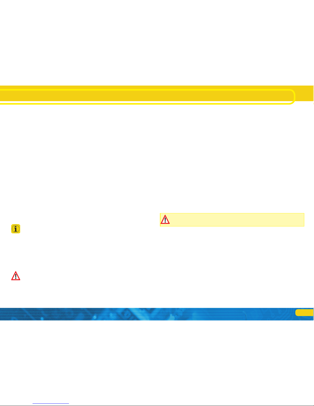
5.2.4. Feedback inputs
Through RailCom® the SwitchPilot can send the current turnout
position back to the digital control unit. For this the turnout needs
to have the corresponding feedback contacts which must be connected to feedback contact input FB A and/or FB A (see Figure
6 for details).
6. Connection to the digital system
We recommend setting all parameters of the SwitchPilot prior to
installing the unit on your layout.
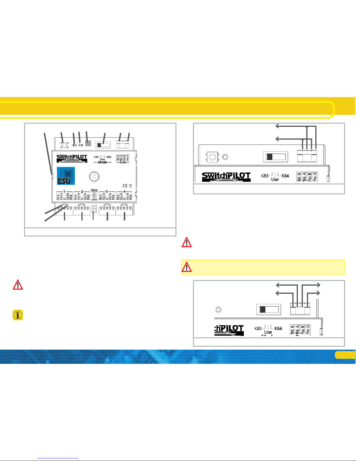
6.1. Connecting elements of the SwitchPilot
Figure 1 shows the SwitchPilot
a) Wire turnouts, signals, un-couplers or similar devices to the ter-
minals of the (transistor) outputs 1 to 4. The terminals FB A and
FB B are used for status feedback of the device.
b) This multi-pin connector serves to wire two commercially
available RC-Servos (e. g.: Graupner®, Futaba® or ESU) and
represents the outputs 5 and 6 of the SwitchPilot.
c) The power supply for the SwitchPilot and all the devices con-
nected to it are wired to the terminals Pw A und Pw B. We
recommend a filtered DC power supply (such as ESU 50119)
as well as the digital track voltage can be used.
d) The screw terminals Trk A and Trk B connect the SwitchPilot
with the power output of a command station (e.g. booster
output) transmitting the digital commands.
e) The switch controlling the operating modes allows you to
select any of the supported modes such as k83, user mode and
k84-mode (also compare with chapter 5.2.1).
f) The LED „PROG” in conjunction with the
g) programming button helps you to set the digital address of the
SwitchPilot. This process is described in chapter 7.
h) Power-LED: This is on once power is supplied to the decoder.
j) The extension socket / plug connect the SwitchPilot and the
SwitchPilot Extension mechanically and electrically.
k) Decoder ground – needed for manual turnout operation
m) Monitor-LED for Output OutA: Lits when the output is active
n) Monitor-LED for Output OutB: Lits when the output is active
9
6.2. Power supply from the digital system
For smaller layouts with only a few devices to be switched simultaneously the power supply of the digital system may be used.
The screw terminals Pw A and Pw B are wired in parallel to the
terminal Trk A and Trk B.
Depending on the used solenoid devices the digital control unit
might not be able to supply enough current for a safe operation. In this case an external transformer which can supply enough
current for these solenoid devices needs to be connected to the
SwitchPilot.
When using certain solenoid devices (i.e. Märklin® K track turnouts or PECO® motors) you should consider an external supply
of SwitchPilot).
6.3. Separate power supply
For larger layouts with many devices controlled by SwitchPilots
and simultaneously active we recommend to utilise a separate
power supply; in this manner the power for switching the devices
is not drawn from the track and thus reduces the load on the
digital system.
Only use commercially available equipment designed for model
trains and also take note of the maximum voltage as stated in
chapter 15 in order to avoid any potential damage.
This way of connecting cannot be used for programming on the
programming track, compare chapter 7.2.1.
Figure 1: SwitchPilot
j g) f)
k) e) d) c)
a) a)
b)
a) a)
h)
m)
n)
Connect to track output of
a digital sytsem
Figure 2: SwitchPilot uses digital system for power supply
conneted
to transformer
connect to track output
of digital system
Figure 3: seperate power supply for Switch Pilot
Connection to the digital system
10
Transistor outputs
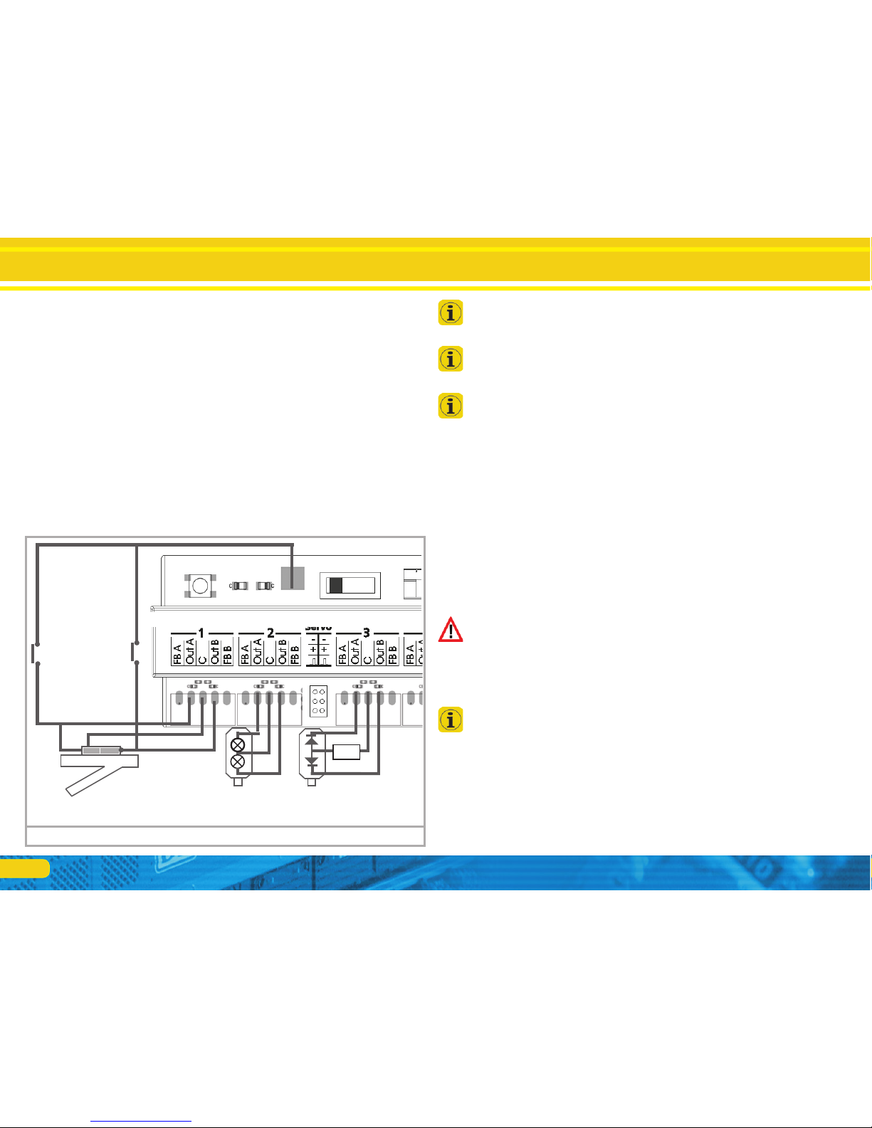
6.4. Wiring of transistor outputs
6.4.1. Connecting double-coil solenoids
You may use all commercially available double-coil solenoid drives
by all major manufacturers with SwitchPilot.
Figure 4 shows how to wire output 1:
a) The common wire of the solenoid is wired to screw terminal
Out C.
b) The wire leading to the first coil is connected to terminal Out
A.
c) The wire leading to the second coil is connected to terminal
Out B.
Should the aspect shown on your control panel not be as desired
(in other words: if straight and diverging route are exchanged)
simply swap the wires between terminals Out A and Out B.
SwitchPilot can also handle PECO® turnouts. However, their current consumption is so high that you must adjust the overload
setting of the SwitchPilot. Please refer to chapter 9.3. for details.
As shown in Figure 4 the double-coil turnouts can be switched
with two optional push buttons without a digital command. The
needed ground solder pad is not available on all SwitchPilot surfaces.
6.4.2. Wiring daylight signals and light bulbs or LEDs
If you use daylight signals with incandescent lamps (light bulbs)
or LEDs you must set the corresponding output to continuous
mode.
If the signal has incandescent lamps as shown for output 2 in figure 5 you may wire the lamps directly to the terminals of the
SwitchPilot.
In order to limit the current for signals with LEDs a resistor must
be wired in series with the LEDs. This is shown for output 3 in
figure 5.
Please check if your signal already has a built-in resistor. Applying
power without this resistor will destroy the LEDs immediately!
If there is no resistor in place you must wire this resistor marked
“R” in series to the LEDs. Subject to the supply voltage and the
desired brightness of the signal the resistor should have a rating of
about 1 kohm to 2.2 kohm.
The screw terminal C of each output has positive potential. Therefore the cathode of the LEDs must be connected to the terminals
Out A respectively Out B.
R
Activation
through button is possible.
Figure 4: Connection to transistor outputs 1-4
 Loading...