

Page 1
Page 2

Operation manual for M RS 420 ESTYMA control unit
2
Contents
GENERAL INFORMATION .......................................................................................... 3
INTRODUCTION .........................................................................................................3
USE ............................................................................................................................4
SAFETY PRECAUTIONS ...............................................................................................6
DISPOSAL OF OLD EQUIPMENT .................................................................................7
APPLICABILITY OF THE MANUAL ................................................................................7
WIRING SYSTEM ....................................................................................................... 8
GENERAL REQUIREMENTS .........................................................................................8
LOCATION ..................................................................................................................8
ACCESSORIES .............................................................................................................9
ADDITIONAL CONTROL PANEL ..............................................................................9
ROOM TEMPEATURE REGULATOR .......................................................................9
OPERATING THE UNIT ............................................................................................. 10
MENU NAVIGATION ................................................................................................10
BOILER OPERATION MODES ....................................................................................12
WEATHER-COMPENSATED MODE WITH MIXER ACTUATOR CONTROL..............12
MANUAL MODE ..................................................................................................12
SUMMER MODE .................................................................................................13
BOILER TEMPERATURE SETTING..............................................................................13
CONTROL OF THE FOUR-WAY MIXING VALVE .........................................................14
HEATING CURVE SELECTION ....................................................................................15
AMOUNT OF AIR, LAMBDA SENSOR – POWER TEST MODE .....................................18
AIR DURING IGNITION .............................................................................................20
PUMPS .....................................................................................................................20
HOT TAP WATER ......................................................................................................20
HOT TAP WATER TEMPERATURE SETTING .........................................................20
HOT WATER PRIORITY ........................................................................................21
HOT TAP WATER HYSTERESIS .............................................................................21
HOT TAP WATER BOILER SETTING ......................................................................21
MENU LANGUAGE ...................................................................................................22
START UP .................................................................................................................22
FIRST BOILER IGNITION ............................................................................................23
ALARMS AND SAFEGUARDS ....................................................................................23
TECHNICAL DATA .....................................................................................................25
Page 3

Operation manual for M RS 420 ESTYMA control unit
3
Thank you for choosing our product and congratulations on a good
decision. We will be grateful for comments concerning the unit’s
performance.
ESTYMA electronics
Team
GENERAL INFORMATION
INTRODUCTION
The boiler operation control unit ESTYMA control M RS is a modern
microprocessor system which controls not only the boiler, but also the central
heating system in weather-compensated and hot tap water modes.
The unit controls the amount of the fuel fed through on and off operation of the
motor of the fuel feeder, and the amount of the air supplied to the combustion
process. Thanks to solid state relays (SSRs), the blower has variable speed
control and the reliability of the unit controlling the feeder motor has been
greatly increased.
Automatic fuel ignition. The M RS ESTYMA control unit provides automatic
fuel ignition in the retort.
Measurement of waste gas temperature. The control unit measures waste
gas temperature which is an essential parameter in a boiler with automatic start
up. Waste gas temperature readouts are also very useful when inspecting the
boiler and adjusting its operation.
Weather-compensated control ensures highest thermal comfort because the
temperature of the heating medium is controlled depending on the outdoor
temperature. Control is effected through the mixing valve actuator.
Page 4

Operation manual for M RS 420 ESTYMA control unit
4
Thanks to an advanced operation algorithm and the possibility of controlling
numerous parameters, the unit can be very flexibly adjusted to the needs of
the heating system.
The controller has an output testing function. The function is available in the
MAINTENANCE MODE and it allows to check the correctness of electrical
connections and the working order of the controlled equipment (pumps, blower,
feeder, mixing valve actuator) prior to starting the boiler.
A large alphanumeric display facilitates communication between the unit and
the user and the interface is very easy to use.
A new intuitive menu in several languages: Polish, English, German, French,
Lithuanian, Russian.
A Lambda sensor ensures optimum supply of air to the combustion process,
thereby simplifying the work of the operator; it also reduces fuel consumption
and improves combustion, reducing emissions of harmful substances to the
environment (optional boiler equipment).
The pneumatic fuel feeding control system allows the boiler to operate for long
periods of time without the need to add fuel.
The heat exchanger cleaning control system ensures that the boiler retains
high efficiency without the need to clean the exchanger.
USE
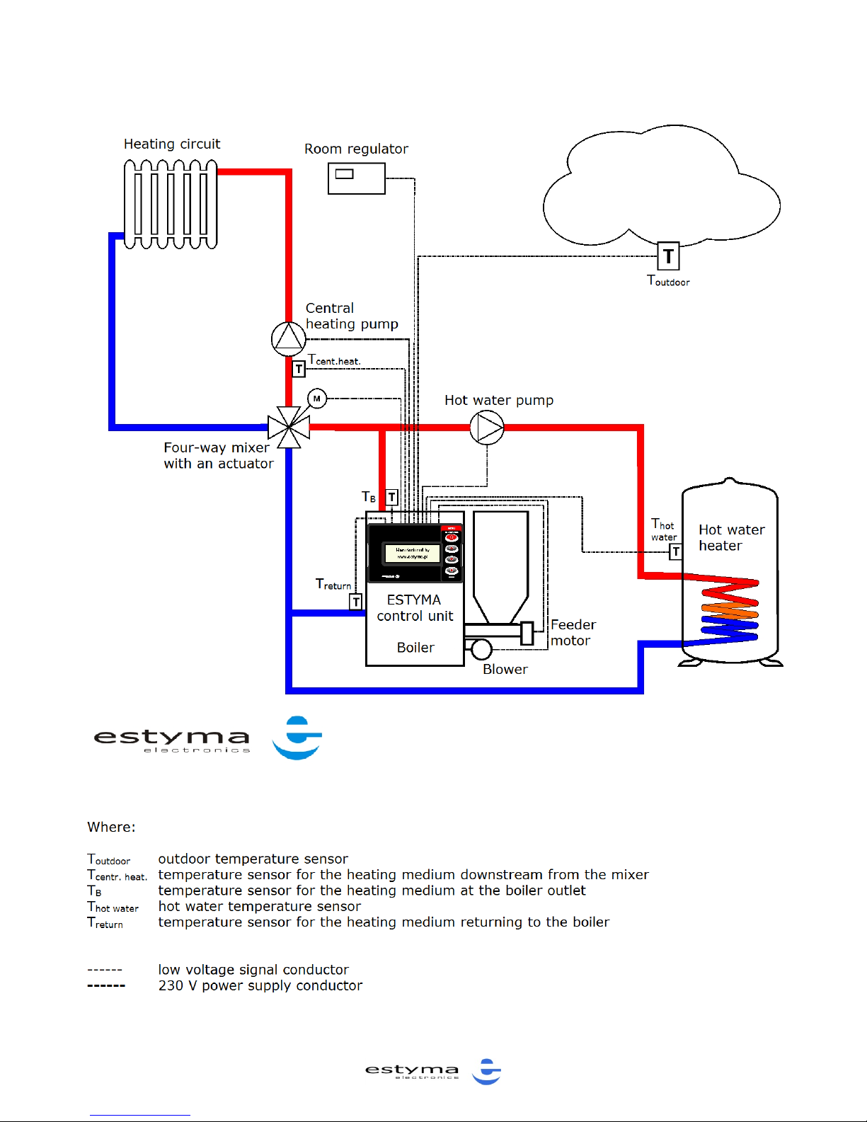
The figure below shows the operation flowchart of the M RS PID ESTYMA control
unit.
Page 5
Operation manual for M RS 420 ESTYMA control unit
5
Page 6

Operation manual for M RS 420 ESTYMA control unit
6
SAFETY PRECAUTIONS
Warning – risk of electric shock.
Before assembly or disassembly of the unit, disconnect the power supply in the
switchgear.
Read this operation manual carefully and thoroughly before using the unit.
Keep this operation manual and refer to it whenever you work with this unit in the
future.
Apply all the rules and heed all the warnings included in the unit operation manual.
Make sure that the unit is not damaged. In case of any doubts, do not use the unit and
contact the supplier.
In case of any doubts concerning the safe operation of the unit, contact the supplier.
Pay special attention to all warning signs on the unit casing and its package.
Use the unit as intended.
The unit is not a toy. Do not allow children to play with it.
Under no circumstances children should be allowed to play with any parts of the
package of the unit.
Access to small parts such as clamping screws or bolts should be secured against
children. Such elements may be delivered with the unit and may result in choking when
swallowed by a child.
Do not make any mechanical or electrical changes to the unit. Such changes may cause
the unit to malfunction and fail to meet the relevant standards, leading to an adverse
impact on the performance of the unit.
Do not insert any objects into the unit through openings (e.g. ventilation grills), as this
may cause short circuiting, electric shock, fire or damage to the unit.
Do not allow water, humidity or dust to enter the unit, as this may cause short
circuiting, electric shock, fire or damage to the unit.
Provide adequate ventilation of the unit, do not cover or block the ventilation grills, and
ensure that there is free flow of air around the unit.
The unit should be installed indoors unless it is adapted for outdoor operation.
Do not expose the unit to mechanical impacts and vibrations.
When connecting the unit to power supply, make sure that the parameters of the
supply network are within the unit’s operating range.
In order to avoid the risk of electric shock, connect the unit to a socket with an
earthing pin. The socket must be properly earthed by a licensed electrician.
When connecting the unit, make sure that it does not overload the electrical circuit.
Avoid connecting the unit to one circuit with motors and other equipment that causes
impulse interference (e.g. washing machines, fridges, ...)
It is absolutely necessary to cut off power supply before connecting any cables or
peripherals to the unit.
Remove the plug from the socket in order to completely de-energize the unit, especially
if you do not intend to use the unit for a longer period of time.
Protect the power lead against damage; it should be laid in a way that ensures that
nobody treads on it; no objects should stand on the power lead.
All electrical connections must be as shown in the electrical assembly drawings and
must comply with national and/or local regulations concerning electrical connections.
Page 7

Operation manual for M RS 420 ESTYMA control unit
7
This unit contains no parts that may be replaced by the user. All maintenance work
except for cleaning, fuse replacement (when the unit is de-energized), and function
setting, should be performed by an authorized service provider.
Before doing any maintenance work, you must cut off the power supply to the unit.
Do not clean the casing of the unit with petrol, solvents or any other chemicals that
may damage the casing of the unit. Using a soft cloth is recommended.
If the power lead is damaged, the unit must not be used. The damaged lead must be
replaced by a maintenance service provider, with a new one having the same
parameters as the original lead.
DISPOSAL OF OLD EQUIPMENT
This electronic equipment is made of materials which are partly
recyclable. Therefore, when the equipment has reached the end of
its service life, take it to an electrical and electronic equipment
recycling centre or to the manufacturer. The equipment must not
be disposed of with other household waste.
APPLICABILITY OF THE MANUAL
This instruction manual is applicable to M RS ESTYMA control units with software
versions up to 9.1. The software version is displayed in the welcome message
after connecting the unit to the power supply. Description of changes in higher
versions is available on the manufacturer’s website at: www.estyma.pl
Page 8

Operation manual for M RS 420 ESTYMA control unit
8
WIRING SYSTEM
GENERAL REQUIREMENTS
Read this operation manual carefully and thoroughly before you start
using the unit.
The person installing the unit should have sufficient technical experience.
Copper wire connections should be designed to work in temperatures of
up to +75ºC .
All connections made must be as shown in the electrical wiring assembly
drawings and must be compliant with national and/or local regulations
concerning electrical connections.
LOCATION
The unit is intended for indoor installation only. After selecting the location, make
sure that it meets the following requirements:
The location must be free from excessive humidity and from flammable or
corrosive vapours.
The unit must not be installed near high power electrical equipment,
electrical machines or welding equipment.
The temperature in the location must not exceed 60ºC and should not be
lower than 0ºC. Humidity should be within the range from 5% to 95%,
with no vapour condensation taking place.
WARNING !!! The connections should be made while the unit is cut off from the
power supply (de-energized). The connections should be made by a licensed
professional.
Page 9
Operation manual for M RS 420 ESTYMA control unit
9
ACCESSORIES
ADDITIONAL CONTROL PANEL
The controller may be equipped with an additional control panel – the Pellets
control 420. The panel may be installed in another location, e.g. in a flat, for
remote control of the system. For additional information, please contact estyma
electronics – see the contact details on the last page of this manual.
ROOM TEMPEATURE REGULATOR
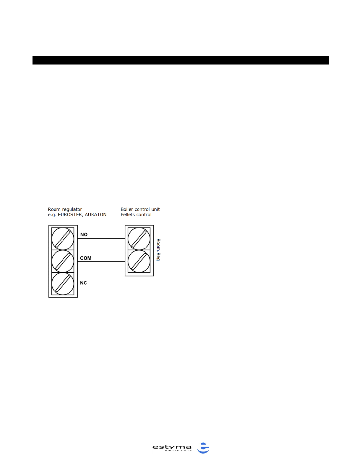
The M RS ESTYMA controller can work with any temperature room regulator with
closing contacts.
The room regulator should be installed in a
location which is representative in terms of
the temperature in the flat, at a height of
1.5 – 2m.
Do not install the regulator near heat
sources (e.g. TV set, radiators), in places
exposed to direct solar radiation or
draughts, as it will adversely affect the
performance of the system.
Figure: Connection of a room regulator
Page 10
Operation manual for M RS 420 ESTYMA control unit
10
OPERATING THE UNIT
MENU NAVIGATION
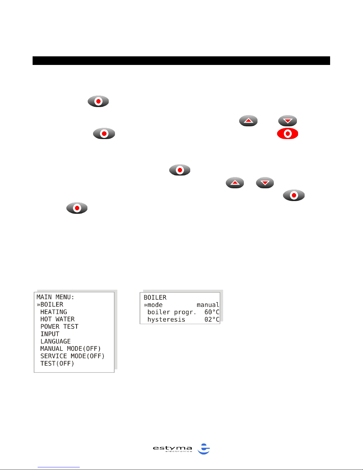
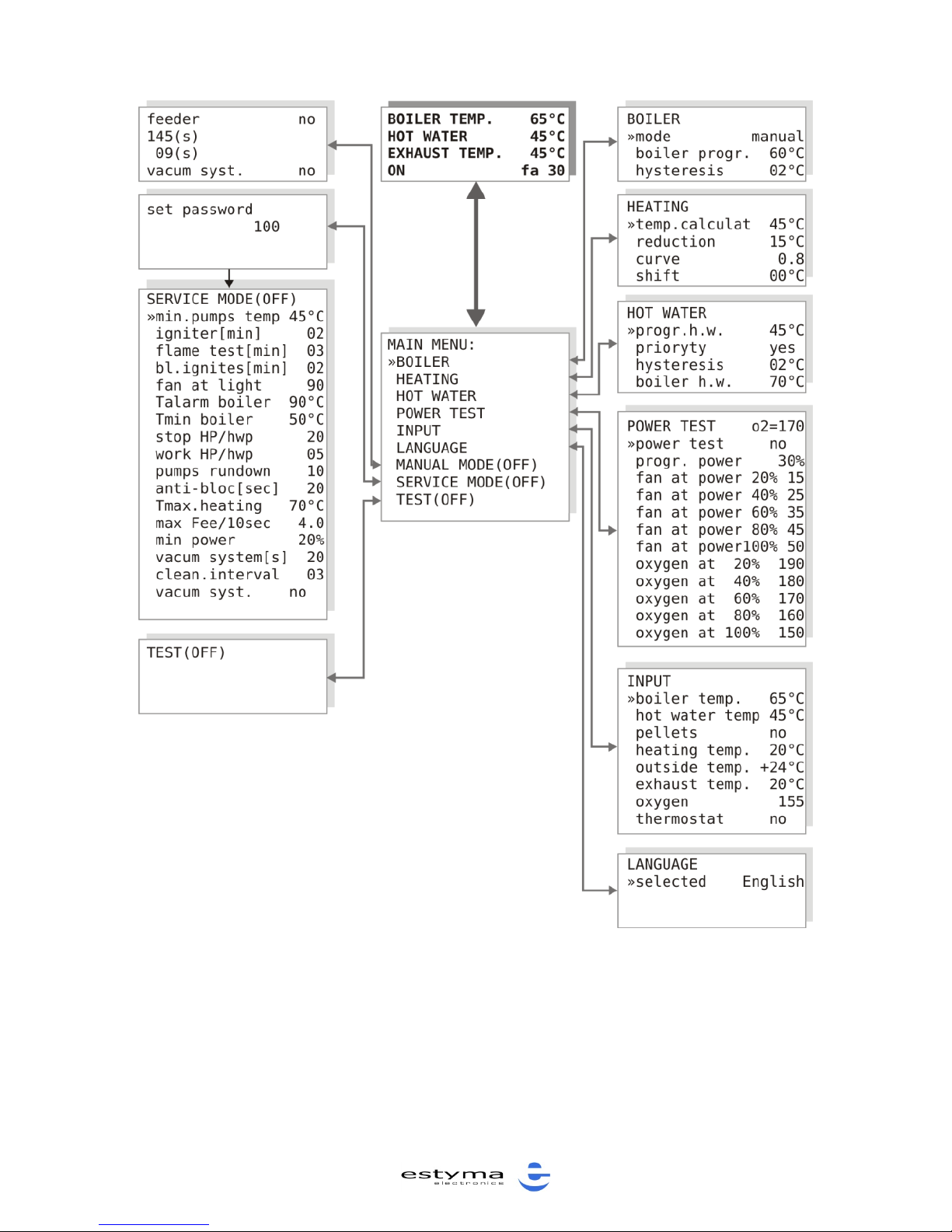
The unit has a hierarchical menu.
Press “ENTER” to enter the Main Menu.
- browse the Main Menu (written in capital letters) using and buttons.
Press “ENTER” to enter the selected submenu. Press “ESC” to enter
a higher level. The Main Menu is shown in Figure 2.
- submenus are used to display and change operation parameters. In order to
change a parameter, press “ENTER” . The parameter changed is displayed
in cycles. In order to edit the parameter value, press or arrow buttons.
When editing, you may cancel the changes made by pressing “ECS” . Press
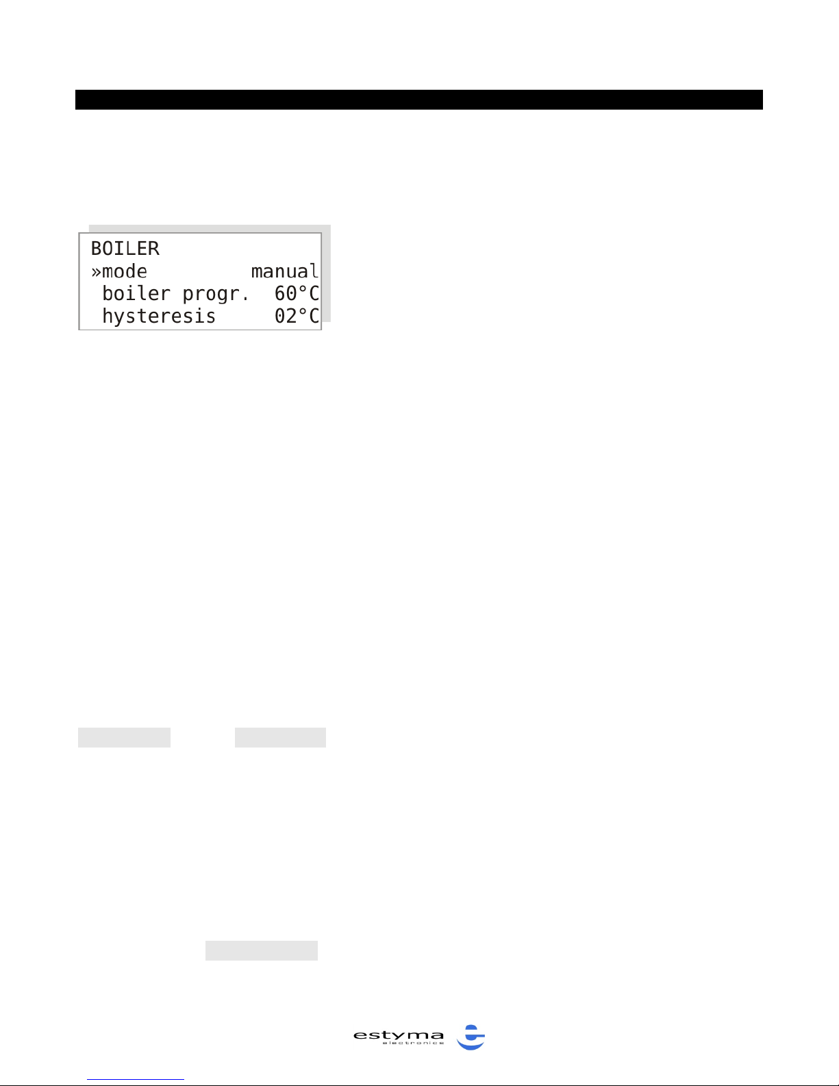
“ENTER” to approve changes. The BOILER submenu is shown in Figure 3 as
an example.
The whole menu is shown in Figure 4.
NOTE!!! Data is saved whenever the main screen is displayed.
Figure 2: MAIN Menu
Figure 3: BOILER
Submenu
Page 11
Operation manual for M RS 420 ESTYMA control unit
11
Figure 4: MENU.
Page 12
Operation manual for M RS 420 ESTYMA control unit
12
BOILER OPERATION MODES
The boiler can work in one of the following modes: weather-compensated, manual
or summer mode.
NOTE!!! The boiler operation modes differ in the
way the boiler temperature is set. Even if the
manual boiler operation mode has been selected,
the mixer actuator continues to be controlled
(provided that the required sensors have been
installed).
WEATHER-COMPENSATED MODE WITH MIXER ACTUATOR CONTROL
NOTE!!! The controller will work in this mode provided that the central heating
temperature sensor has been connected.
In this mode, the outdoor temperature sensor and central heating temperature
sensor, delivered with the unit, must be installed. The boiler temperature is
determined by linear approximation of the programmable heating curve, so there
is no need to change the boiler temperature manually when the outdoor
temperature changes. As a rule, nights are colder than days. The boiler
temperature is a function of the outdoor temperature.
The boiler temperature setting is calculated using the heating curve and it is
20ºC higher.
When the contacts of the room temperature regulator are open, the
temperature in the heating circuit will be decreased by the value of the parameter
“reduction”, in the “HEATING” submenu.
NOTE!!! When tap water needs to be heated, the controller automatically
changes the boiler temperature to heat the water as quickly as possible, and then
it returns to operating according to the heating curve.
MANUAL MODE
In this mode, the user sets the set boiler operation temperature manually using
the parameter “boiler progr”. When tap water needs to be heated, the controller
automatically changes the boiler temperature to heat the water as quickly as
Figure 5: BOILER submenu
Page 13

Operation manual for M RS 420 ESTYMA control unit
13
possible, and then it returns to operating according to the temperature set by the
user.
Operation with the mixing valve actuator.
When the central heating temperature sensor is connected to the controller (to
provide the controller with information on the actuator), boiler temperature can
be set after switching to manual mode. The mixer will be controlled in the same
way as in the weather-compensated mode, but the temperature will be constant.
NOTE!!! The term “manual mode” refers only to manual setting of the boiler
temperature. The mixer is controlled independently; mixer control is effected in
the same way in the manual and weather-compensated modes.
SUMMER MODE
This mode of the controller is used in summer to heat water. In this mode, the
central heating circulation pump is not turned on (unless there is an alarm
signal).
The boiler temperature is set manually using the parameter “boiler temp”.
NOTE!!! The central heating pump will be turned on when the boiler overheating
alarm is activated.
BOILER TEMPERATURE SETTING
The boiler temperature setting is an internal parameter of the controller; it may
be one of the following three temperatures:
- in the weather-compensated mode, the boiler temperature setting is
calculated using the heating curve on the basis of the outdoor temperature,
- in the summer and manual modes, the user sets the temperature using the
“temp. setting” parameter in the BOILER submenu,
when tap water is being heated, the control unit selects the “boiler temp.
for hot water” setting, which may be different than in the manual or the
weather-compensated mode.
Page 14
Operation manual for M RS 420 ESTYMA control unit
14
NOTE !!! If the boiler temperature for hot tap water is lower than the
temperature in the manual or weather-compensated mode, the boiler will operate
at the higher of the two temperature settings.
CONTROL OF THE FOUR-WAY MIXING VALVE
The controller controls the four-way mixing valve. The purpose is to maintain the
set temperature of the heating medium in the central heating circuit. The
controller also protects the boiler against excessively low temperature of the
heating medium returning from the heating circuit. Protection of the boiler has
priority over control of the temperature in the central heating circuit. When the
temperature of the heating medium returning from the installation is too low, the
valve is turned down. When the minimum temperature of the returning medium is
exceeded, the element responsible for maintaining the required temperature
downstream from the mixer takes over control. The temperatures are set in the
HEATING submenu.
The central heating temperature setting is
calculated by the controller when the boiler
operates in the weather-compensated or manual
mode. The temperature setting downstream from
the mixer depends on the status of the room
regulator:
- closed contacts (heating required) – the
temperature is determined from the heating curve.
- open contacts (heating not required) – the temperature downstream from the
mixer is lower by the value of the parameter “reduction” in the “HEATING”
submenu.
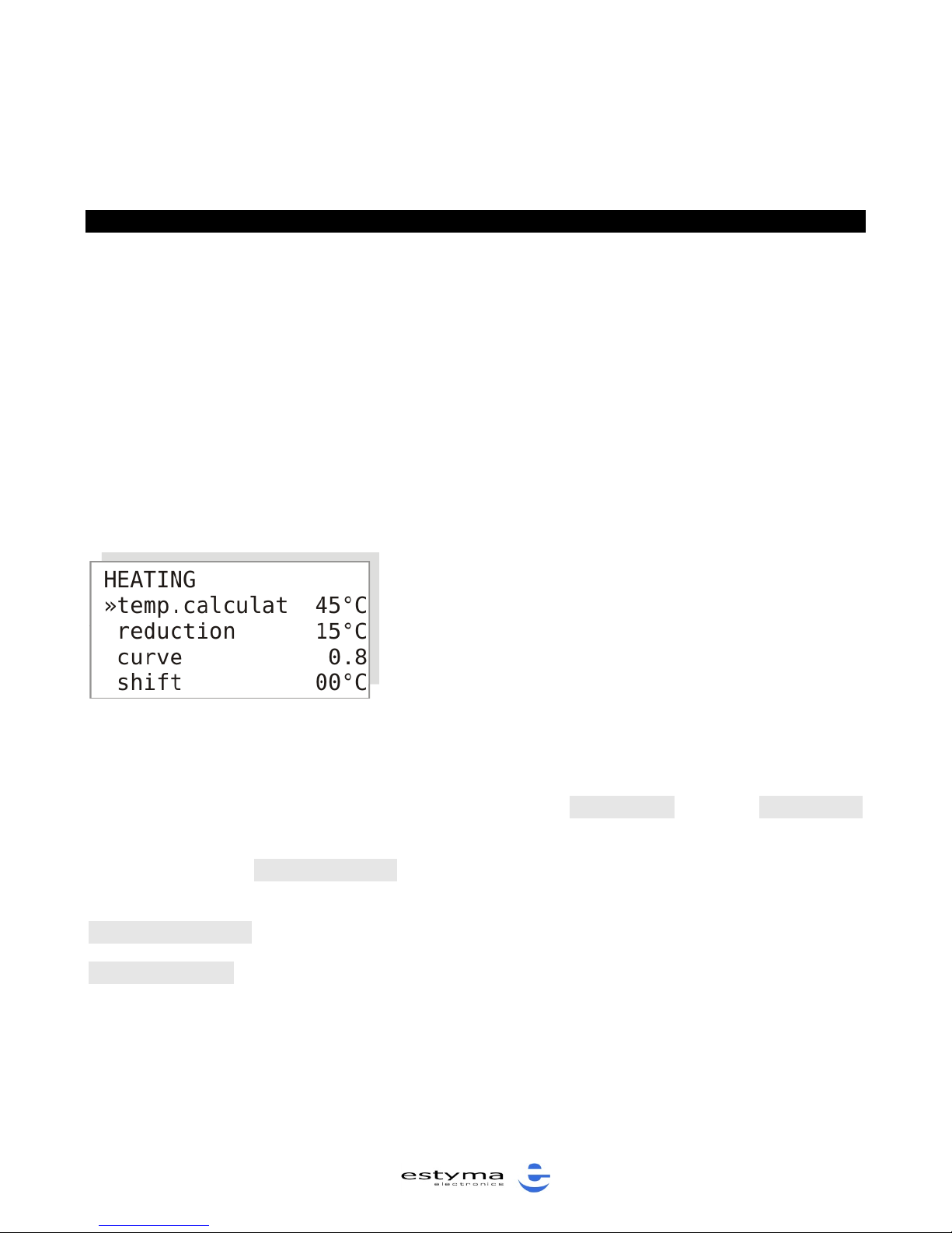
The parameter “temp.calculat” shows the current calculated value of the
temperature setting of the central heating circuit.
“SERVICE MODE” parameters affecting mixer actuator control:
“Tmax.heating” - is the upper limit of the temperature of the heating medium
downstream from the central heating mixer.
Figure 6: HEATING submenu
Page 15

Operation manual for M RS 420 ESTYMA control unit
15
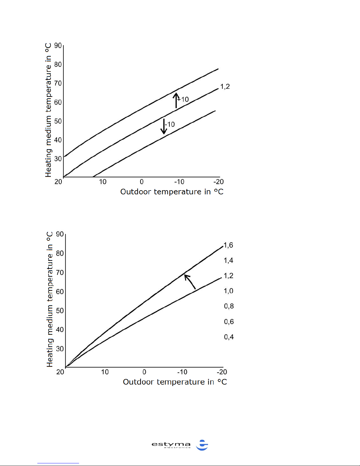
HEATING CURVE SELECTION
In the weather-compensated mode, it is very important to properly select the
heating curve so that it matches the building’s heat loses. If the heating curve is
selected correctly, the room temperature is virtually constant and almost identical
with the value set by the user, regardless of the outdoor temperature.
In many cases, the correct heating curve can only be determined as a result of
numerous adjustments over a considerable period of time.
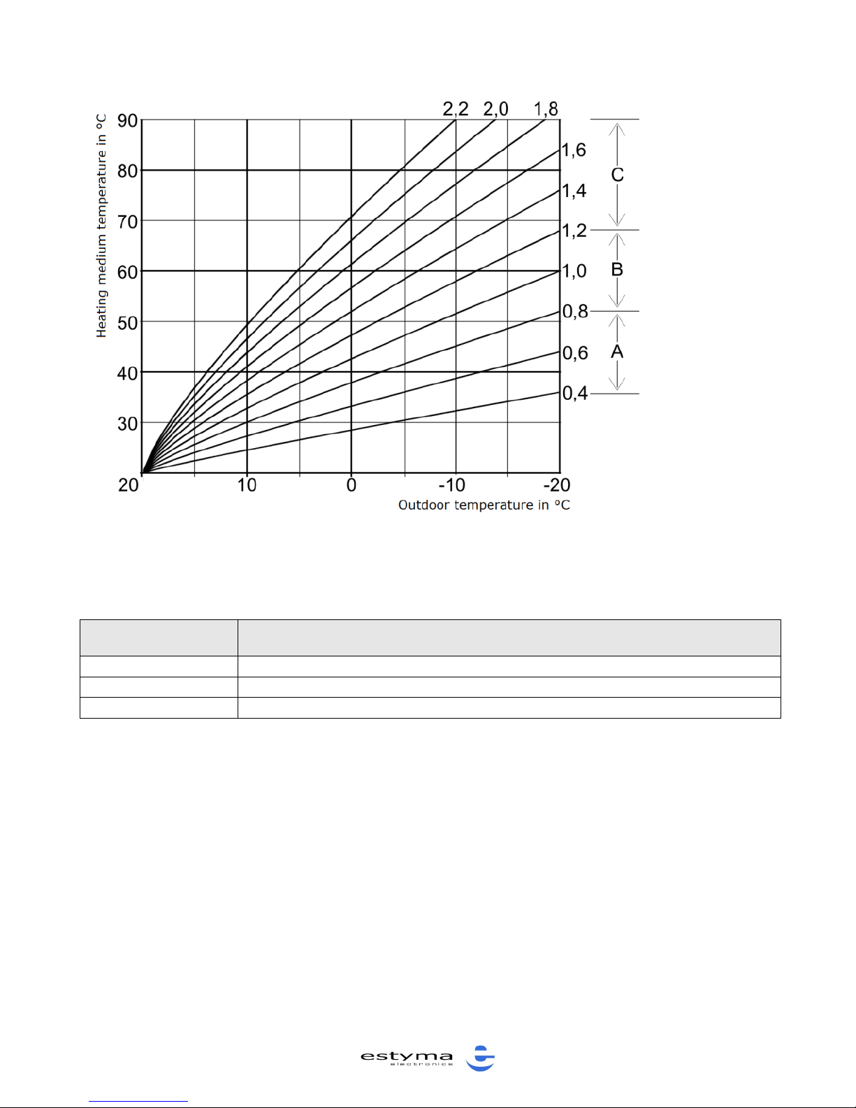
In the first try, you should select a curve from ranges A, B or C. The descriptions
of the ranges are included in Table No. 2.
Precise curve adjustment should be made in line with the adjustment guidelines
included in Table No. 1.
Adjustment guidelines:
PROBLEM
ADJUSTMENT
Room temperature is too low within the
whole range of outdoor temperatures
Increase the curve offset.
Room temperature is too high within the
whole range of outdoor temperatures
Decrease the curve offset.
Room temperature is OK in the
transition period but it is too cold when
outdoor temperatures are low.
Increase the curve slope.
Room temperature is OK in the
transition period but it is too hot when
outdoor temperatures are low.
Decrease the curve slope.
Room temperature is OK when outdoor
temperatures are low but it is too cold in
the transition period.
Decrease the curve slope, increase the
curve offset.
Room temperature is OK when outdoor
temperatures are low but it is too hot in
the transition period.
Increase the curve slope,
decrease the curve offset.
Table 1: Heating curve selection.
Page 16
Operation manual for M RS 420 ESTYMA control unit
16
SYMBOL
INSTALLATION TYPE
A
Floor heating system
B
Low temperature heating system
C
Heating system with temperature exceeding 75°C
Table 2: Heating system types.
Figure 7: Heating curves
Page 17
Operation manual for M RS 420 ESTYMA control unit
17
Figure 8: Heating curve offset
Figure 9: Modification of heating curve slope
Page 18

Operation manual for M RS 420 ESTYMA control unit
18
AMOUNT OF AIR, LAMBDA SENSOR – POWER TEST MODE
The combustion process requires the supply of air, the amount of which depends
on the type of fuel and the power of the heating unit. Therefore, the optimal
amount of air should be set for each type of fuel and each burner power level.
This should be done by the person who starts up the control unit. The parameters
are saved in the non-volatile memory of the control unit.
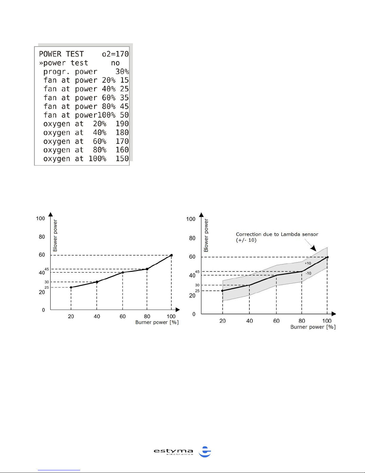
In order to set the optimal amount of air, one should:
- set the type of fuel corresponding to the fuel to be used,
- turn on the control unit,
- enter the POWER TEST submenu and run the “power test mode”.
- set the amount of air for 20, 40, 60, 80, 100% of the burner power. The values
will be calculated by approximation method from the selected curves. See Figure
11.
If the control system includes the optional Lambda module, oxygen values should
be set in a similar fashion for the various burner power levels. The parameters
should be set in line with the boiler manufacturer’s specifications, or on the basis
of the results of waste gas analysis at the different burner power levels.
If the blower power is controlled using the optional Lambda sensor module, the
blower power may be adjusted within the range of ±10 adjustment units. This
relationship is shown in Figure 12.
NOTE!!! Turn off the chimney sweep mode once you have completed the
adjustments.
When adjustments are made in the power test mode, automatic burner power
control is deactivated so as to allow measurements and analyses at constant
burner power.
Page 19
Operation manual for M RS 420 ESTYMA control unit
19
Figure 10: POWER TEST submenu
Figure 11: Blower power curve
Figure 12: Blower power curve with
Lambda-based control
Page 20
Operation manual for M RS 420 ESTYMA control unit
20
AIR DURING IGNITION
The amount of air required for ignition is set separately because it differs from
the amount of air during normal operation of the burner.
Air amount during ignition is set using the “bl. ignites” parameter in the
“SERVICE MODE” submenu.
PUMPS
In order to be efficient and last long, the boiler must operate within a certain
temperature range. This is why the circulation pumps should only run when the
temperature exceeds a certain minimum level. The “min. pumps temp.”
parameter is available in the “SERVICE MODE” submenu.
The hot water pump runs only when the temperature of the heating medium in
the boiler is higher than the water temperature in the hot tap water tank. In this
way, losses of energy stored in the heated tap water are prevented.
HOT TAP WATER
Boilers with the M RS 420 control unit are ideal for heating tap water both in the
heating season and in other parts of the year.
HOT TAP WATER TEMPERATURE SETTING
The CTN-02 sensor, supplied with the
unit, should be installed in the hot water
tank.
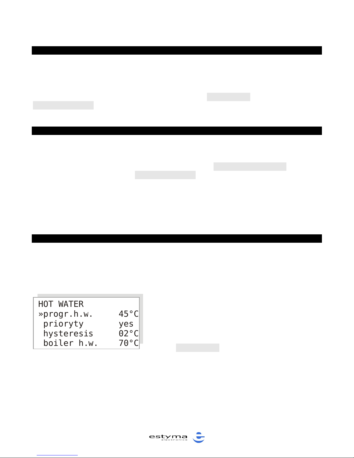
Set the hot tap water temperature in the
HOT WATER submenu. The temperature
should not be too high in order to
prevent excessive heat losses during
water storage and distribution. The default setting is 45ºC. Figure 13 shows the
HOT WATER submenu.
Figure 13: HOT WATER submenu
Page 21
Operation manual for M RS 420 ESTYMA control unit
21
HOT WATER PRIORITY
The boiler control unit may operate in two hot tap water heating modes which,
until now, have typically featured only in gas and oil-fired boiler control systems,
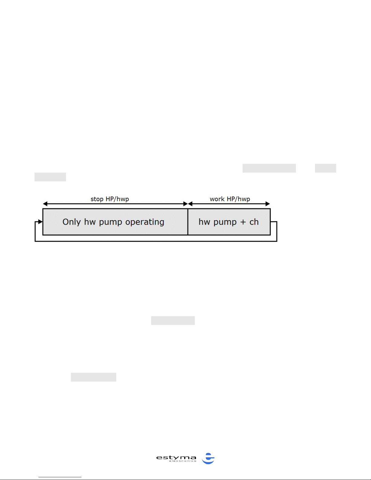
i.e. the hot water priority mode (recommended) and no priority mode. In the hot
water priority mode, when tap water needs to be heated, only the hot water
pump is running, while the central heating pump is at a standstill. In this way,
water takes much less time to heat up to the set temperature.
In order to prevent room temperature from dropping while hot tap water is being
heated, the central heating pump will start up and run for 5 min. (default setting)
if the hot water pump runs for more than 20 min. (default setting) and the set
hot tap water temperature is not attained.
The relevant SERVICE MODE submenu parameters are: „stop HP/hwp” and „work
HP/hwp”.
HOT TAP WATER HYSTERESIS
The hot tap water hysteresis parameter determines the point at which hot tap
water should be heated. Heating begins when the water temperature in the hot
tap water tank drops below the set temperature less the value of the hysteresis
parameter. The value of the “hysteresis” parameter may be set in the HOT
WATER submenu.
HOT TAP WATER BOILER SETTING
The boiler temperature setting during hot tap water heating may be adjusted
using the “boiler h.w.” parameter in the HOT WATER submenu.
NOTE!!! The “boiler h.w.” setting must be higher than the “progr.h.w.” in the
HOT WATER submenu.
Figure 14: Pump operation when hot water priority is selected
Page 22
Operation manual for M RS 420 ESTYMA control unit
22
MENU LANGUAGE
The menu of the control unit is available in a number of languages: Polish,
English, German, French. The preferred language may be selected in the
“LANGUAGE” submenu. The default setting is Polish.
START UP
Press the “ON/OFF/ESC” button for 3 seconds in order to turn the control unit on
or off. The current status of the unit is displayed on the main screen:
OFF – the control unit is turned off (only alarm functions are active while the
blower and fuel feeder are controlled manually)
ON – the control unit is on
NOTE!!! When OFF is displayed on the screen, the control unit is actually in a
standby mode and is energized; in case of an alarm, the control unit will initiate
the appropriate remedial actions (i.e. it will either turn on the pumps or the
feeder).
If you intend to not to use the boiler for a considerable period of time, or to do
any maintenance on the boiler, you absolutely must de-energize the control unit
by cutting off power supply.
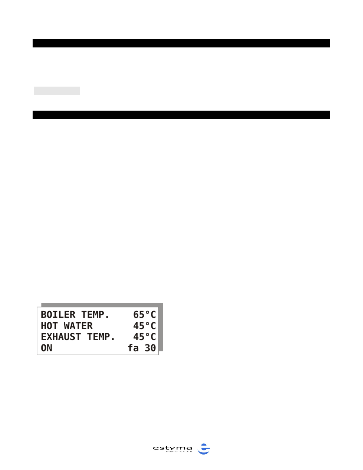
The display (main screen) shows the current status of the different pieces of
equipment.
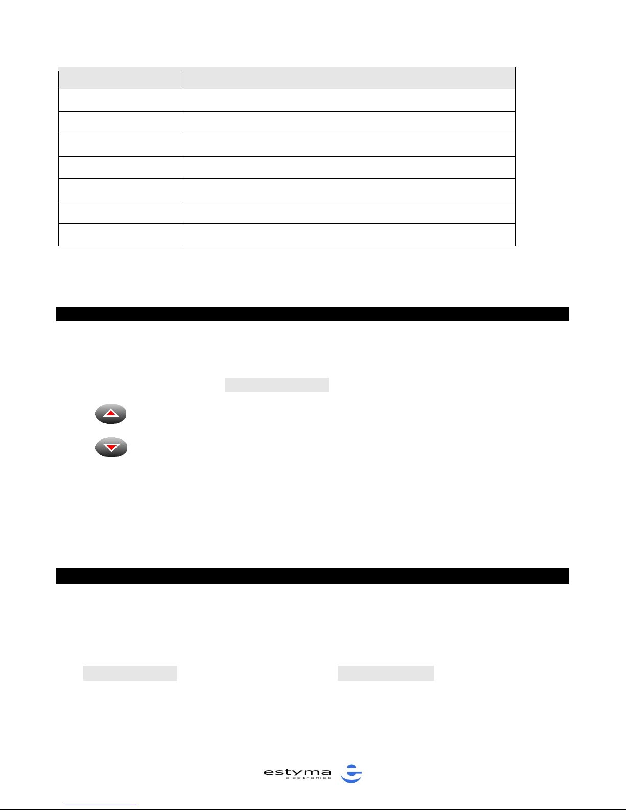
If the abbreviation of a particular piece of equipment is displayed, it means that
the control unit has turned it on.
Figure 15: Main screen
Page 23
Operation manual for M RS 420 ESTYMA control unit
23
ABBREVIATION
DESCRIPTION
HP
central heating circulation pump is on
WP
hot tap water circulation pump is on
lig
heating element is on
fee
fuel feeder is on
fa 20
blower is on; current blower power level
00
mixer closing
01
mixer opening
Table 3: Equipment abbreviations
FIRST BOILER IGNITION
If you work with a feeder, you should fill the bin with fuel and then turn the
feeder on manually in order to feed the fuel into the combustion chamber. To do
this, you should select the “MANUAL MODE” submenu.
Press to turn the feeder on/off.
Press to turn suction on/off.
After you press the button, the feeder will run for 30 seconds, filling the retort
with fuel about half-way. Once this happens, turn the boiler control unit ON; the
fuel will ignite automatically.
ALARMS AND SAFEGUARDS
The flashing of the display screen of the control unit is an alarm signal. Press
“ENTER” to display information about the alarm. The control unit activates the
following types of alarms:
- boiler overheating; alarm is activated when the boiler temperature exceeds
the “Talarm boiler” which may be set in the SERVICE MODE. When this happens,
the control unit turns on the circulation pumps and keeps them running until the
boiler temperature drops, regardless of the operating mode selected.
Page 24

Operation manual for M RS 420 ESTYMA control unit
24
NOTE!!! The circulation pumps will be turned on and will run in pre-alarm mode
when the temperature rises to 2ºC less than the boiler alarm temperature. If the
temperature does not rise above the alarm level, information on the incident will
not be saved in the control unit’s memory.
- no flame/no fuel; the alarm is activated when there is no fuel or no flame in
the burner.
- check suction system; the alarm is activated if the suction system has made
three consecutive failed attempts to ignite the fuel.
NOTE!!! Once an alarm has been activated you should determine and eliminate
its cause.
- the Independent Thermal Boiler Protection (ITBP) is independent of the
microprocessor system. An independent thermal switch will cut off the power
supply to the blower if the boiler temperature exceeds 94ºC.
Page 25

Operation manual for M RS 420 ESTYMA control unit
25
TECHNICAL DATA
PARAMETER
VALUE
Power supply
~230V/50Hz
±10%
Power uptake by the controller
<5VA
Carrying capacity of outputs:
Central heating pump
100W
Hot water pump
100W
Lighter
400W
Blower
150W
Feeder motor
200W
Automatic exchanger
cleaning/suction motor
100W
Mixer actuator
50W
Boiler temp. setting range
60-85ºC
Hot tap water setting range
35-70ºC
Temperature measurement
accuracy
±2ºC
Ambient temperature
0-60ºC
Humidity
5-95%, no
condensation
Boiler alarm temp.
80-95ºC
Table 4: Technical data
We reserve the right to change the design and technical data of the unit.
Page 26

Operation manual for M RS 420 ESTYMA control unit
26
estyma electronics
Gajewo, Al.Lipowa 4
11-500 Giżycko
POLAND
phone +48 87 429 86 75
fax +48 87 429 86 75
[email protected]
www.estyma.pl
 Loading...