

Page 1

ProNet Series AC Servo User's Manual
(Version :V2.10)
Page 2

Copyright © 2011 ESTUN AUTOMATION TECHNOLOGY CO., LTD
All rights reserved. No part of this publication may be reproduced, stored in a retrieval system, or transmitted, in any form, or
by any means, mechanical, electronic, photocopying, recording, or otherwise, without the prior written permission of ESTUN.
No patent liability is assumed with respect to the use of the information contained herein.
Page 3

ProNet Series AC Servo User's Manual
- 1 -
About this manual
This manual describes the following information required for designing and maintaining ProNet series servo drives.
•Specification of the servo drives and servomotors.
•Procedures for installing the servo drives and servomotors.
•Procedures for wiring the servo drives and servomotors.
•Procedures for operating of the servo drives.
•Procedures for using the panel operator.
•Communication protocols.
•Ratings and characteristics.
Intended Audience:
•Those designing ProNet series servo drive systems.
•Those installing or wiring ProNet series servo drives.
•Those performing trial operation or adjustments of ProNet series servo drives.
•Those maintaining or inspecting ProNet series servo drives.
Page 4

ProNet Series AC Servo User's Manual
- 2 -
Safety Precautions
■ Do not connect the servomotor directly to the local electrical network.
Failure to observe this may result in damage to servomotor.
■ Do not plug or unplug connectors from servo drive when power is on.
Failure to observe this may result in damage to servo drive and servomotor.
■Please note that even after power is removed, residual voltage still remains in the capacitor inside the servo drive. If
inspection is to be performed after power is removed, please wait 5 minutes to avoid risk of electrical shock.
■ Keep servo drives and other devices separated by at least 10mm.
The servo drive generates heat. Install the servo drive so that it can radiate heat freely. When installing servo drives
with other devices in a control panel, provide at least 10mm space between them and 50mm space above and below
them. Please install servo drives in an environment free from condensation, vibration and shock.
■ Perform noise reduction and grounding properly.
Please comply with the following instructions to avoid noise generated by signal lines.
1. Separate high-voltage cables from low-voltage cables.
2. Use cables as short as possible.
3. Single point grounding is required for the servomotor and servo drive (grounding resistance 100Ω or below).
4. Never use a line filter for the power supply in the circuit.
■ Conduct a voltage resistance test for the servo drive under the following conditions:
1. Input voltage: AC 1500Vrms, 1 minute
2. Braking current: 100mA
3. Frequency:50/60Hz
4. Voltage applied point: Between L1, L2,L3 terminals and frame ground.
■ Use a fast-response type ground-fault interrupter.
For a ground-fault interrupter, always use a fast-response type or one designed for PWM inverters. Do not use a
time-delay type.
■ Do not make any extreme adjustments or setting changes of parameters.
Failure to observe this caution may result in injury or damage to the product due to unstable operation.
■ The servomotor cannot be operated by turning the power on and off.
Frequently turning the power ON and OFF causes the internal circuit elements to deteriorate, resulting in unexpected
problems. Always start or stop the servomotor by using reference pulses.
Page 5

ProNet Series AC Servo User's Manual
- 3 -
—Contents—
About this manual ........................................................................................................................................................... - 1 -
Safety Precautions .......................................................................................................................................................... - 2 -
Chapter 1 ........................................................................................................................................................................ - 7 -
Checking Products and Parts Names .............................................................................................................................. - 7 -
1.1 Checking Products on Delivery ......................................................................................................................... - 7 -
1.1.1 Servomotor ............................................................................................................................................ - 7 -
1.1.2 Servo drive ............................................................................................................................................ - 8 -
1.2 Part Names ..................................................................................................................................................... - 15 -
1.2.1 Servomotor .......................................................................................................................................... - 15 -
1.2.2 Servo drive .......................................................................................................................................... - 16 -
Chapter 2 ...................................................................................................................................................................... - 21 -
Installation ..................................................................................................................................................................... - 21 -
2.1 Servomotor ..................................................................................................................................................... - 21 -
2.1.1 Storage ................................................................................................................................................ - 21 -
2.1.2 Installation Sites .................................................................................................................................. - 21 -
2.1.3 Installation Alignment ........................................................................................................................... - 22 -
2.1.4 Installation Orientation ......................................................................................................................... - 22 -
2.1.5 Handling Oil and Water ........................................................................................................................ - 22 -
2.1.6 Cable Tension ...................................................................................................................................... - 23 -
2.1.7 Install to the Client ............................................................................................................................... - 23 -
2.2 Servo Drive ..................................................................................................................................................... - 23 -
2.2.1 Storage ................................................................................................................................................ - 23 -
2.2.2 Installation Sites .................................................................................................................................. - 23 -
2.2.3 Installation Orientation ......................................................................................................................... - 24 -
2.2.4 Installation Method .............................................................................................................................. - 24 -
Chapter 3 ...................................................................................................................................................................... - 26 -
Wiring ............................................................................................................................................................................ - 26 -
3.1 Main Circuit Wiring .......................................................................................................................................... - 26 -
3.1.1 Names and Functions of Main Circuit Terminals .................................................................................. - 26 -
3.1.2 Typical Main Circuit Wiring Examples .................................................................................................. - 27 -
3.2 I/O Signals ...................................................................................................................................................... - 31 -
3.2.1 Examples of I/O Signal Connections ................................................................................................... - 31 -
3.2.2 I/O Signal Names and Functions ......................................................................................................... - 32 -
3.2.3 I/O Signal Connector (CN1) Terminal Layout ...................................................................................... - 34 -
3.2.4 Interface Circuit ................................................................................................................................... - 35 -
3.3 Wiring Encoders .............................................................................................................................................. - 36 -
3.3.1 Connecting an Encoder(CN2) .............................................................................................................. - 36 -
3.3.2 Encoder Connector(CN2) Terminal Layout ......................................................................................... - 38 -
3.4 Communication Connection ............................................................................................................................ - 38 -
3.4.1 Communication Connector(CN3) Terminal Layout .............................................................................. - 38 -
3.4.2 Communication Connector(CN4) Terminal Layout .............................................................................. - 39 -
3.5 Standard Wiring Examples .............................................................................................................................. - 40 -
3.5.1 Single-phase 200V ProNet-02A~04A/ProNet-E-02A~04A ............................................................... - 40 -
Page 6

ProNet Series AC Servo User's Manual
- 4 -
3.5.2 Three-phase 200V ProNet-08A~50A/ProNet-E-08A~50A ................................................................ - 41 -
3.5.3 Three-phase 400V ProNet-10D~75D/ProNet-E-10D~50D ............................................................... - 42 -
3.5.4 Three-phase 400V ProNet-1AD~2BD ................................................................................................ - 43 -
3.5.5 Single-phase 100V ProNet-02B/ProNet-E-02B ................................................................................... - 44 -
3.5.6 Single-phase 100V ProNet-04B /ProNet-E-04B .................................................................................. - 45 -
3.5.7 Three-phase 100V ProNet-08B/ ProNet-E-08B ................................................................................... - 46 -
3.5.8 Position Control Mode ......................................................................................................................... - 47 -
3.5.9 Speed Control Mode ............................................................................................................................ - 48 -
3.5.10 Torque Control Mode ......................................................................................................................... - 49 -
3.6 Wiring for Noise Control .................................................................................................................................. - 50 -
3.6.1 Noise Control ....................................................................................................................................... - 50 -
3.6.2 Precautions on Connecting Noise Filter .............................................................................................. - 51 -
3.7 Installation Conditions of EMC Directives ....................................................................................................... - 53 -
3.8 Using More than One Servo Drive .................................................................................................................. - 55 -
3.9 Connecting DC Bus ........................................................................................................................................ - 57 -
Chapter 4 ...................................................................................................................................................................... - 58 -
Operation ...................................................................................................................................................................... - 58 -
4.1 Trial Operation ................................................................................................................................................ - 58 -
4.1.1 Trial Operation for Servomotor Without Load ...................................................................................... - 61 -
4.1.2 Trial Operation for Servomotor without Load from Host Reference ..................................................... - 63 -
4.1.3 Trial Operation with the Servomotor Connected to the Machine .......................................................... - 67 -
4.1.4 Trial Operation for Servomotor with Brakes ......................................................................................... - 68 -
4.1.5 Position Control by Host Controller ...................................................................................................... - 68 -
4.2 Control Mode Selection ................................................................................................................................... - 68 -
4.3 Setting Common Basic Functions ................................................................................................................... - 70 -
4.3.1 Setting the Servo ON Signal ................................................................................................................ - 70 -
4.3.2 Switching the Servomotor Rotation Direction ...................................................................................... - 71 -
4.3.3 Setting the Overtravel Limit Function ................................................................................................... - 72 -
4.3.4 Setting for Holding Brakes ................................................................................................................... - 75 -
4.3.5 Instantaneous Power Loss Settings..................................................................................................... - 78 -
4.4 Absolute Encoders .......................................................................................................................................... - 79 -
4.4.1 Selecting an Absolute Encoder ............................................................................................................ - 79 -
4.4.2 Handling Battery .................................................................................................................................. - 80 -
4.4.3 Replacing Battery ................................................................................................................................ - 81 -
4.4.4 Absolute Encoder Setup(Fn010、Fn011) ............................................................................................ - 81 -
4.5 Operating Using Speed Control with Analog Reference.................................................................................. - 82 -
4.5.1 Setting Parameters .............................................................................................................................. - 82 -
4.5.2 Setting Input Signals ............................................................................................................................ - 83 -
4.5.3 Adjusting Reference Offset .................................................................................................................. - 84 -
4.5.4 Soft Start .............................................................................................................................................. - 87 -
4.5.5 Speed Reference Filter Time Constant ................................................................................................ - 87 -
4.5.6 S-curve Risetime ................................................................................................................................. - 88 -
4.5.7 Using the Zero Clamp Function ........................................................................................................... - 88 -
4.5.8 Encoder Signal Output ........................................................................................................................ - 90 -
4.5.9 Speed coincidence output ................................................................................................................... - 91 -
4.6 Operating Using Position Control .................................................................................................................... - 92 -
Page 7

ProNet Series AC Servo User's Manual
- 5 -
4.6.1 Basic Setting in Position Control .......................................................................................................... - 92 -
4.6.2 Setting the Clear Signal ....................................................................................................................... - 96 -
4.6.3 Setting the Electronic Gear .................................................................................................................. - 96 -
4.6.4 Smoothing ........................................................................................................................................... - 99 -
4.6.5 Low Frequency Vibration Suppression .............................................................................................. - 100 -
4.6.6 Positioning Completion Output Signal ............................................................................................... - 102 -
4.6.7 Reference Pulse Inhibit Function (INHIBIT) ....................................................................................... - 103 -
4.6.8 Position Control (contact reference) ................................................................................................. - 104 -
4.6.9 Position Homing Control (Homing Function)...................................................................................... - 107 -
4.7 Operating Using Torque Control .................................................................................................................... - 110 -
4.7.1 Setting Parameters ............................................................................................................................ - 110 -
4.7.2 Torque Reference Input ..................................................................................................................... - 111 -
4.7.3 Adjusting the Reference Offset .......................................................................................................... - 112 -
4.7.4 Limiting Servomotor Speed During Torque Control ............................................................................ - 113 -
4.8 Operating Using Speed Control with an Internally Set Speed ....................................................................... - 114 -
4.8.1 Setting Parameters ............................................................................................................................ - 115 -
4.8.2 Input Signal Settings .......................................................................................................................... - 116 -
4.8.3 Operating Using an Internally Set Speed ........................................................................................... - 116 -
4.9 Limiting Torque .............................................................................................................................................. - 117 -
4.9.1 Internal Torque Limit .......................................................................................................................... - 117 -
4.9.2 External Torque Limit ......................................................................................................................... - 118 -
4.9.3 Torque Limiting Using an Analog Voltage Reference ........................................................................ - 119 -
4.10 Control Mode Selection ............................................................................................................................... - 120 -
4.10.1 Setting Parameters .......................................................................................................................... - 120 -
4.10.2 Switching the Control Mode ............................................................................................................. - 120 -
4.11 Other Output Signals ................................................................................................................................... - 121 -
4.11.1 Servo alarm output........................................................................................................................... - 121 -
4.11.2 Rotation Detection Output Signal (/TGON) ...................................................................................... - 122 -
4.11.3 Servo Ready (/S-RDY) Output ......................................................................................................... - 122 -
4.11.4 Encoder C Pluse Output (/PGC) ...................................................................................................... - 122 -
4.11.5 Over travel signal output (OT) .......................................................................................................... - 123 -
4.11.6 Servo Enabled Motor Excitation Output(/RD) .................................................................................. - 123 -
4.11.7 Torque Limit Detection Output (/CLT) ............................................................................................... - 123 -
4.11.8 Torque Detection Output (/TCR) ...................................................................................................... - 125 -
4.12 Online Autotuning ........................................................................................................................................ - 125 -
4.12.1 Online Autotuning ............................................................................................................................ - 125 -
4.12.2 Online Autotuning Procedure ........................................................................................................... - 126 -
4.12.3 Setting Online Autotuning ................................................................................................................ - 127 -
4.12.4 Machine Rigidity Setting for Online Autotuning ................................................................................ - 127 -
Chapter 5 .................................................................................................................................................................... - 128 -
Panel Operator ............................................................................................................................................................ - 128 -
5.1 Basic Operation ............................................................................................................................................ - 128 -
5.1.1 Functions on Panel Operator ............................................................................................................. - 128 -
5.1.2 Resetting Servo Alarms ..................................................................................................................... - 128 -
5.1.3 Basic Mode Selection ........................................................................................................................ - 129 -
5.1.4 Status Display Mode .......................................................................................................................... - 129 -
Page 8

ProNet Series AC Servo User's Manual
- 6 -
5.1.5 Operation in Parameter Setting Mode ............................................................................................... - 131 -
5.1.6 Operation in Monitor Mode ................................................................................................................ - 132 -
5.2 Operation in Utility Function Mode ................................................................................................................ - 135 -
5.2.1 Alarm Traceback Data Display ........................................................................................................... - 135 -
5.2.2 Parameter Settings Initialization ........................................................................................................ - 136 -
5.2.3 Operation in JOG Mode ..................................................................................................................... - 137 -
5.2.4 Automatic Adjustment of the Speed Reference Offset ....................................................................... - 138 -
5.2.5 Manual Adjustment of the Speed Reference Offset ........................................................................... - 139 -
5.2.6 Offset-adjustment of Servomotor Current Detection Signal ............................................................... - 140 -
5.2.7 Software Version Display ................................................................................................................... - 142 -
5.2.8 Position Teaching Function ................................................................................................................ - 142 -
5.2.9 Static Inertia Detection ....................................................................................................................... - 142 -
5.2.10 Absolute Encoder Multiturn Data and Alarm Reset .......................................................................... - 143 -
5.2.11 Absolute Encoder Related Alarms Reset ......................................................................................... - 143 -
Chapter 6 .................................................................................................................................................................... - 144 -
MODBUS Communication ........................................................................................................................................... - 144 -
6.1 RS-485 Communication Wiring ..................................................................................................................... - 144 -
6.2 MODBUS Communication Related Parameters ........................................................................................... - 145 -
6.3 MODBUS Communication Protocol .............................................................................................................. - 146 -
6.3.1 Code Meaning ................................................................................................................................... - 146 -
6.3.2 Communication Error Disposal .......................................................................................................... - 152 -
6.3.3 Data Communication Address of Servo State .................................................................................... - 153 -
Chapter 7 .................................................................................................................................................................... - 156 -
Specifications and Characters ..................................................................................................................................... - 156 -
7.1 Servo drive Specifications and Models ......................................................................................................... - 156 -
7.2 Servo drive Dimensional Drawings ............................................................................................................... - 159 -
Appendix A .................................................................................................................................................................. - 162 -
Parameter ................................................................................................................................................................... - 162 -
A.1 Parameter List .............................................................................................................................................. - 162 -
A.2 Description of Parameter Type ..................................................................................................................... - 169 -
A.3 Parameters in detail ...................................................................................................................................... - 170 -
Appendix B .................................................................................................................................................................. - 188 -
Alarm Display .............................................................................................................................................................. - 188 -
Page 9
ProNet Series AC Servo User's Manual
- 7 -
Chapter 1
Checking Products and Parts Names
1.1 Checking Products on Delivery
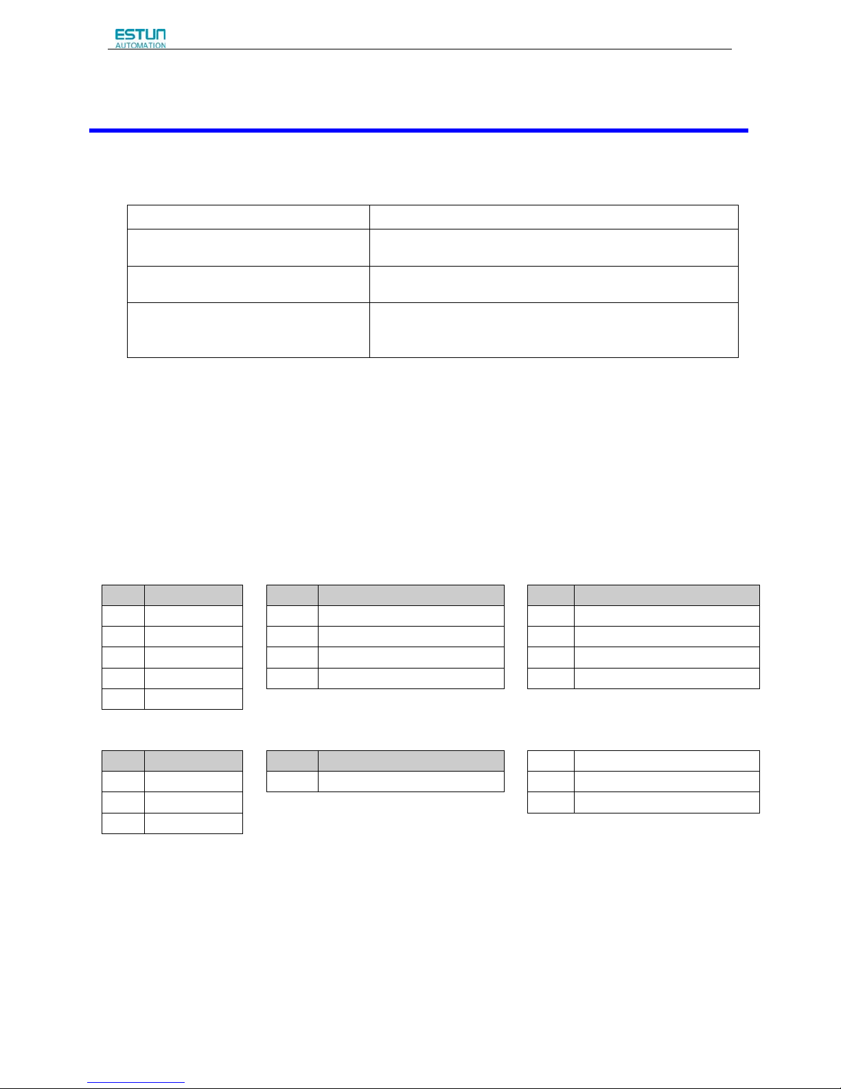
If any of the above items are faulty or incorrect, contact your ESTUN representative or the dealer from whom you
purchased the products.
1.1.1 Servomotor
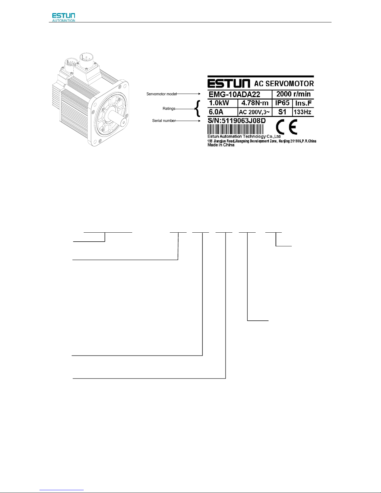
Servomotor Model Designation
EMG– 10 A D A 1 1
ESTUN Servomotor
【1+2】 【3】 【4】 【5】 【6】 【7】
EMG Model
【1+2】Rated Output
【4】Encoder
【7】Option
Code Rated Output Code Encoder Code Option
10 1.0kW D
Incremental encoder:131072P/R
1 None
15 1.5kW S
Absolute encoder:131072P/R
2 With oil seal
20 2.0kW R Resolver 3 With brake(DC 24V)
30 3.0kW P
Incremental Wire-saving Type:2500P/R
4 With oil seal and brake(DC 24V)
50 5.0kW
【3】Voltage
【5】Designing Sequence
【6】Shaft End
Code Voltage Code Designing Sequence Code Shaft End
A 200V AC A Designing sequence 1 Straight without key(Standard)
B 100VAC 2 Straight with key and tap
D 400VAC
Notes:
1. The EMG-30A□A□□, EMG-50A□A□□ servomotors are not mounted with an incremental encoder.
2. There is no brake mounted on the EMG-□□□DA□□ servomotor.
Check Items Comments
Are the delivered products the ones that
were ordered?
Check the model numbers marked on the nameplate on the
servomotor and servo drive.
Is there any damage?
Check the overall appearance, and check for damage or scratches
that may have occurred during shipping.
Does the servomotor shaft rotate smoothly?
If the servomotor shaft can be easily rotated by hand, then the motor
is working normally. However, if a brake is installed on the
servomotor, then it cannot be turned by hand.
Page 10
ProNet Series AC Servo User's Manual
- 8 -
Appearance and Nameplate
1.1.2 Servo drive
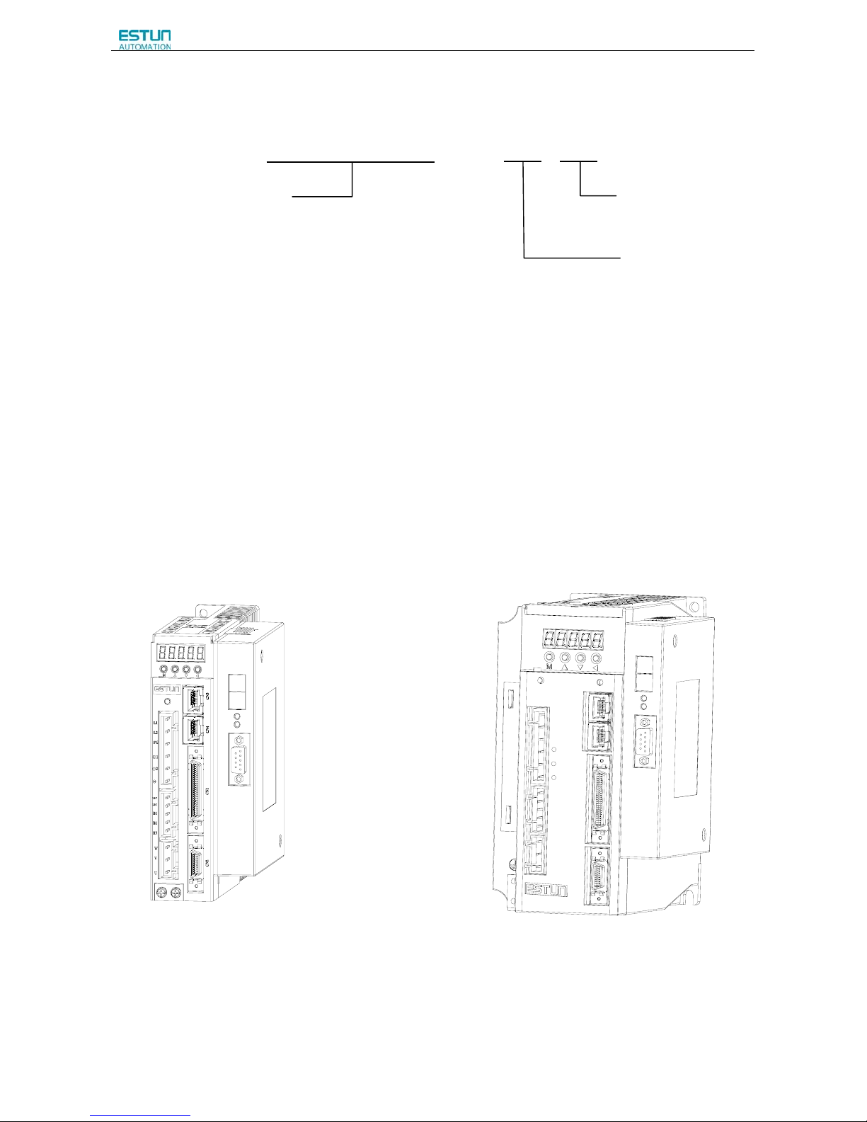
ProNet Servo drive Model Designation
PRONET – 10 A E A -P
Note:
○
1
Resolver, with the feature of high reliability and long service life, is suitable for harsh environments and a wide range
of temperatures and humidity levels. The factory setting for the resolver precision used in the ESTUN servo drive is
4096.
○
2
ProNet-□□□E□ Supports AE100 model. ProNet-□□□M□ does not support extended module.
Rated Output
02 0.2kW
04 0.4 kW
08 0.75 kW
10 1.0 kW
15 1.5 kW
20 2.0 kW
30 3.0 kW
50 5.0 Kw
70 7.0kW
75 7.5 kW
1A 11 kW
1E 15 Kw
2B 22kW
Vol tag e
A 200VAC
B:100VAC
D 400VAC
Control Mode
M Speed control, torque control, position control
E Speed control, torque control, position control (support extended module)
Encoder Interface
A 17-bit serial encoder
Absolute Encoder
B Resolver
○
1
ProNet Model
Extended module type
-D DP100
-E EC100
-P PL100
Page 11
ProNet Series AC Servo User's Manual
- 9 -
ProNet-E Servo drive Model Designation
PRONET–E – 10 A
Note:
○
1
ProNet-E is only available with the wire-saving incremental encoder (2500 P/R)
○2 ProNet-E does not support extended module.
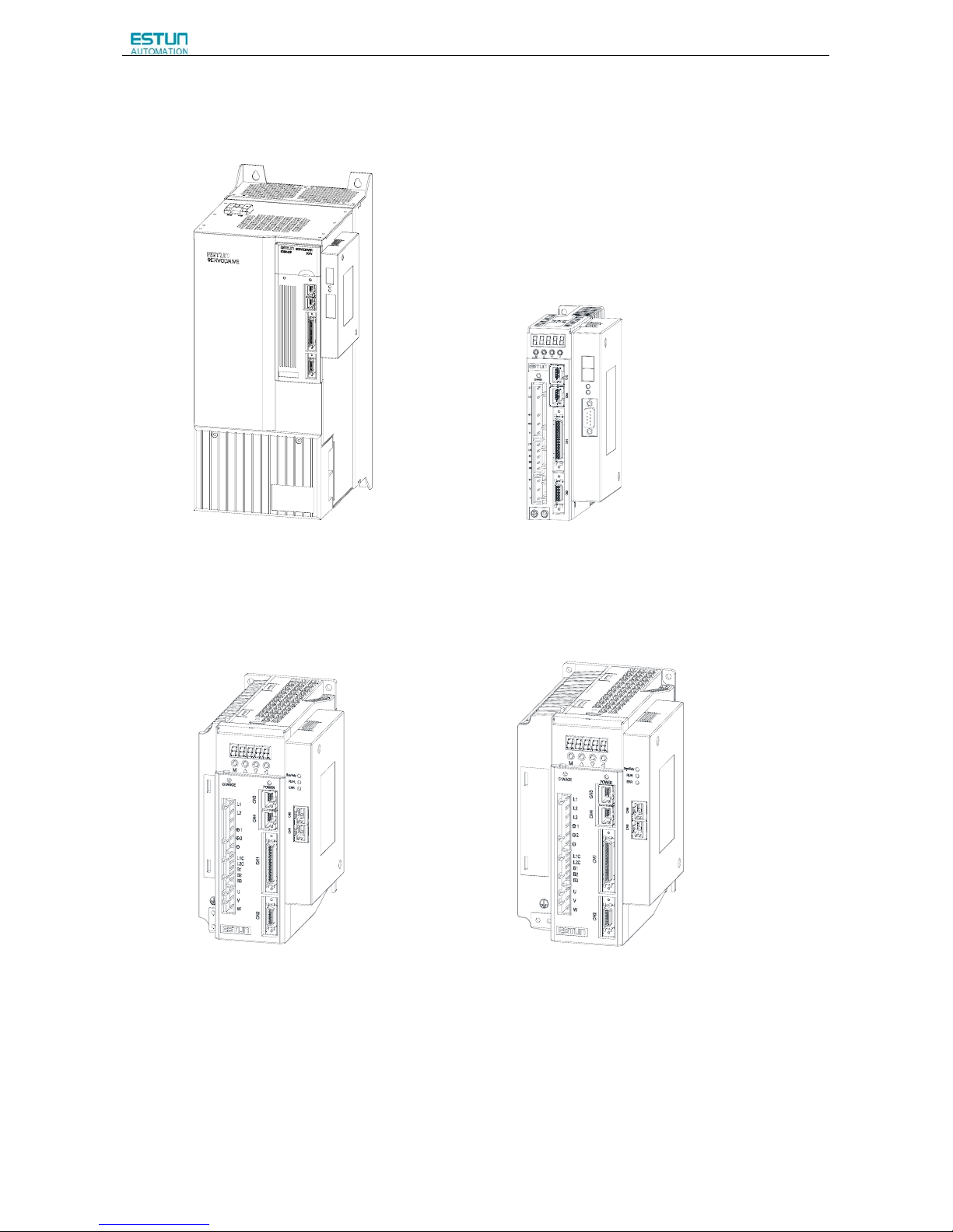
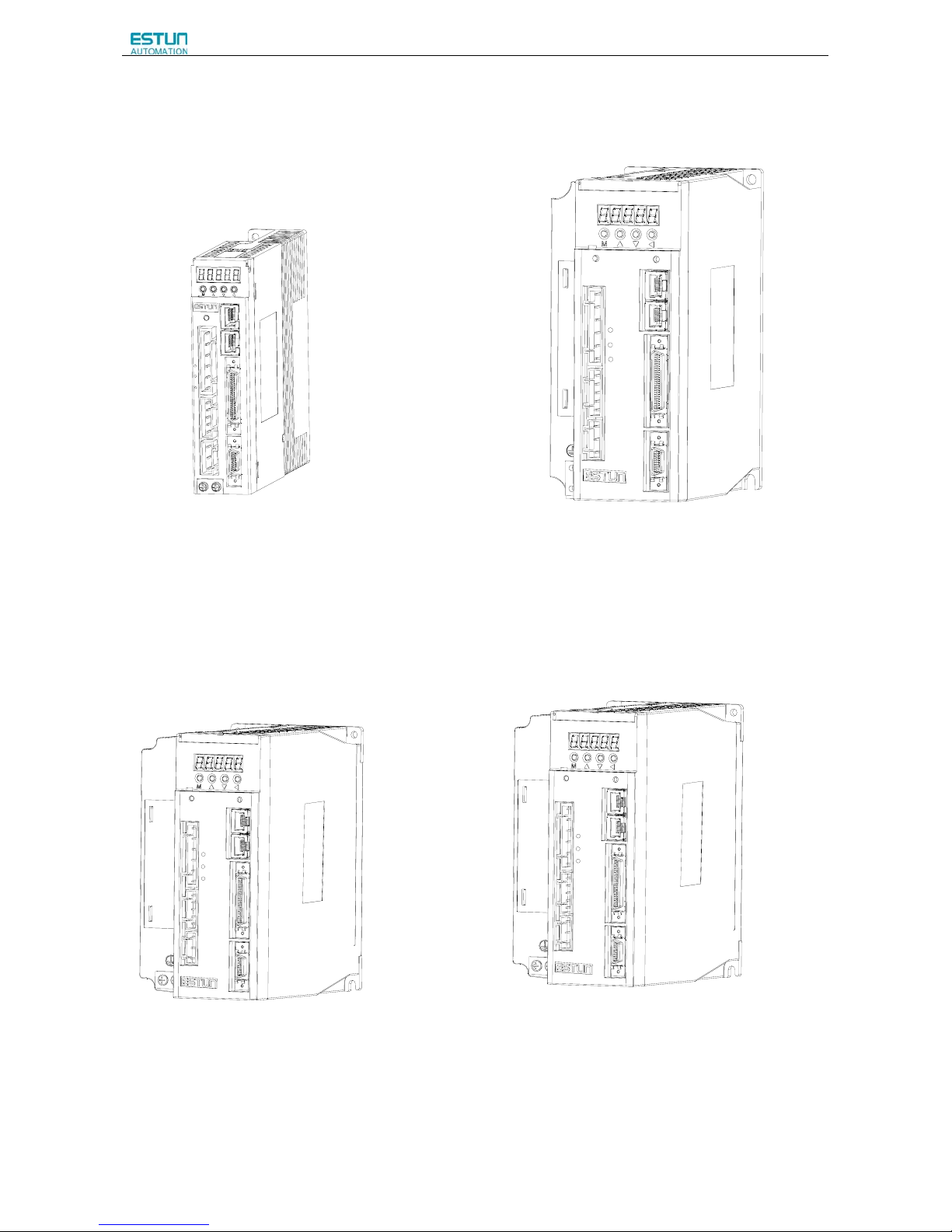
ProNet Servo Drive Appearance
ProNet-02A/04A ProNet-08A/10A
L1
L2
L3
CN3
CN4
CN1
CN2
L1C
L2C
B1
B2
B3
U
V
W
+
-
1
+2
CHARGE POWER
Rated Output
02 0.2kW
04 0.4 kW
08 0.75 kW
10 1.0 kW
15 1.5 kW
20 2.0 kW
30 3.0 kW
50 5.0 kW
Vol tag e
A:200VAC
B:100VAC
D
:400VAC
ProNet-E Model
Page 12

ProNet Series AC Servo User's Manual
- 10 -
ProNet-15A/20A ProNet-10D/15D/20D
L1
L2
L3
CN3
CN4
CN1
CN2
L1C
L2C
B1
B2
B3
U
V
W
+
-
1
+
2
CHARGE POWER
L1
L2
L3
CN3
CN4
CN1
CN2
24V
B1
B2
B3
U
V
W
+
-
1
+
2
CHARGE
POWER
GND
ProNet-30A/50A ProNet-30D/50D/70D/75D
CN3
CN4
CN1
CN2
CHARGE
POWER
L1
L2
L3
L1C
L2C
B1
B2
B3
U
V
W
+
-
1
+
2
CN3
CN4
CN1
CN2
CHARGE
POWER
L1
L2
L3
24V
GND
B1
B2
B3
U
V
W
+
-
1
+
2
Page 13
ProNet Series AC Servo User's Manual
- 11 -
ProNet-1AD/1ED/2BD ProNet-02B
ProNet-04B ProNet-08B
Page 14
ProNet Series AC Servo User's Manual
- 12 -
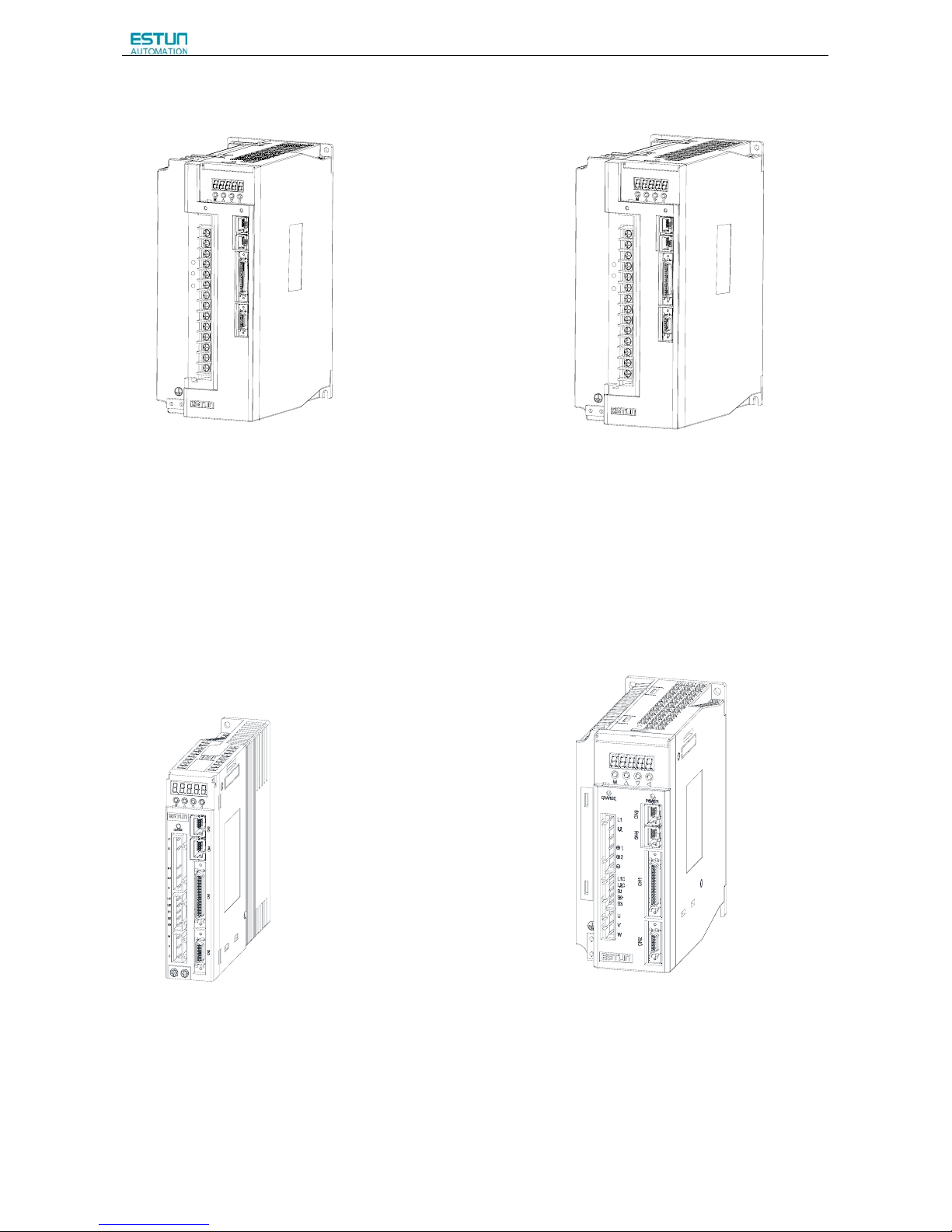
ProNet-E Servo Drive Appearance
ProNet-E-02A/04A ProNet-E-08A/10A
CN3CN4
CN1
CN2
L1
L2
FG
L1C
L2C
-
1
2
+
+
B1
B2
B3
W
V
U
CHARGE
L
1
L
2
L
3
C
N
3
C
N
4
C
N
1
C
N
2
L
1
C
L
2
C
B
1
B
2
B
3
U
V
W
+
-
1
+
2
C
H
A
R
G
E
P
O
W
E
R
ProNet-E-15A/20A ProNet-E-10D/15D/20D
L1
L2
L3
CN3
CN4
CN1
CN2
L1C
L2C
B1
B2
B3
U
V
W
+
-
1
+
2
CHARGE
POWER
L1
L2
L3
CN3
CN4
CN1
CN2
24V
GND
B1
B2
B3
U
V
W
+
-
1
+
2
CHARGE POWER
Page 15
ProNet Series AC Servo User's Manual
- 13 -
ProNet-E-30A/50A ProNet-E-30D/50D
CN3
CN4
CN1
CN2
CHARGE
POWER
L1
L2
L3
L1C
L2C
B1
B2
B3
U
V
W
+-1
+
2
CN3
CN4
CN1
CN2
CHARGE
POWER
L1
L2
L3
24V
GND
B1
B2
B3
U
V
W
+
-
1
+
2
ProNet-E-02B ProNet-E-04B
Page 16
ProNet Series AC Servo User's Manual
- 14 -
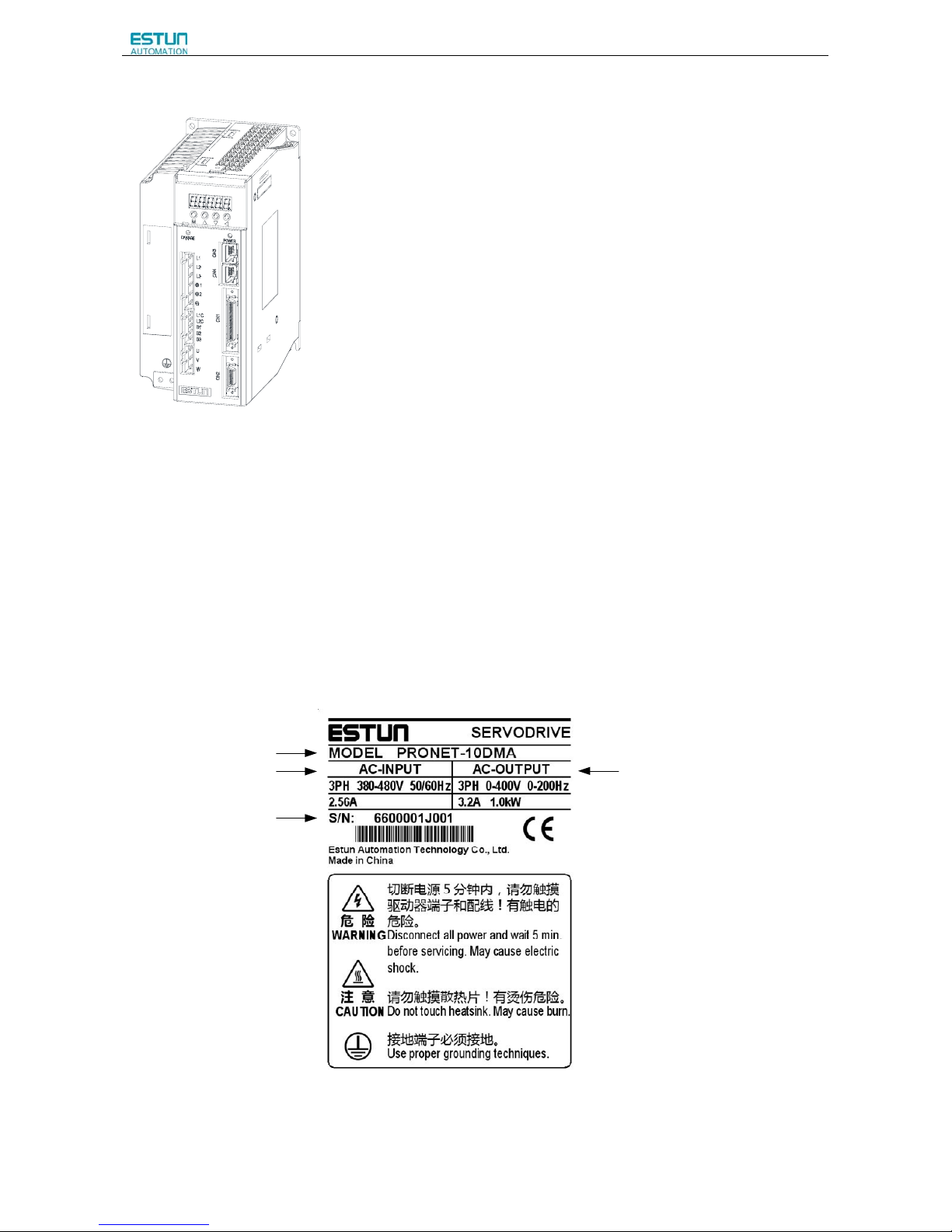
ProNet-E-08B
ProNet Servo Drive Nameplate
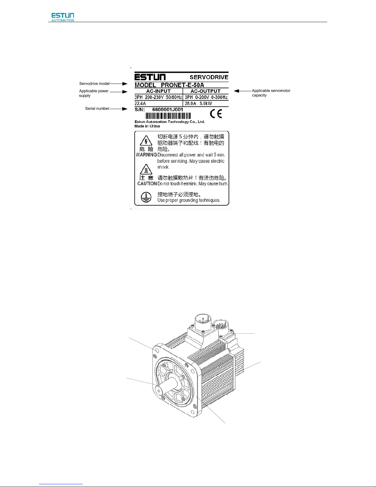
Servodrive model
Applicable power
supply
Applicable servomotor
capacity
Serial number
Page 17
ProNet Series AC Servo User's Manual
- 15 -
ProNet-E Servo Drive Nameplate
1.2 Part Names
1.2.1 Servomotor
Servomotor without gear and brake.
Encoder
Shell
Flange
Output shaft
Mounting hole
Page 18
ProNet Series AC Servo User's Manual
- 16 -
1.2.2 Servo drive
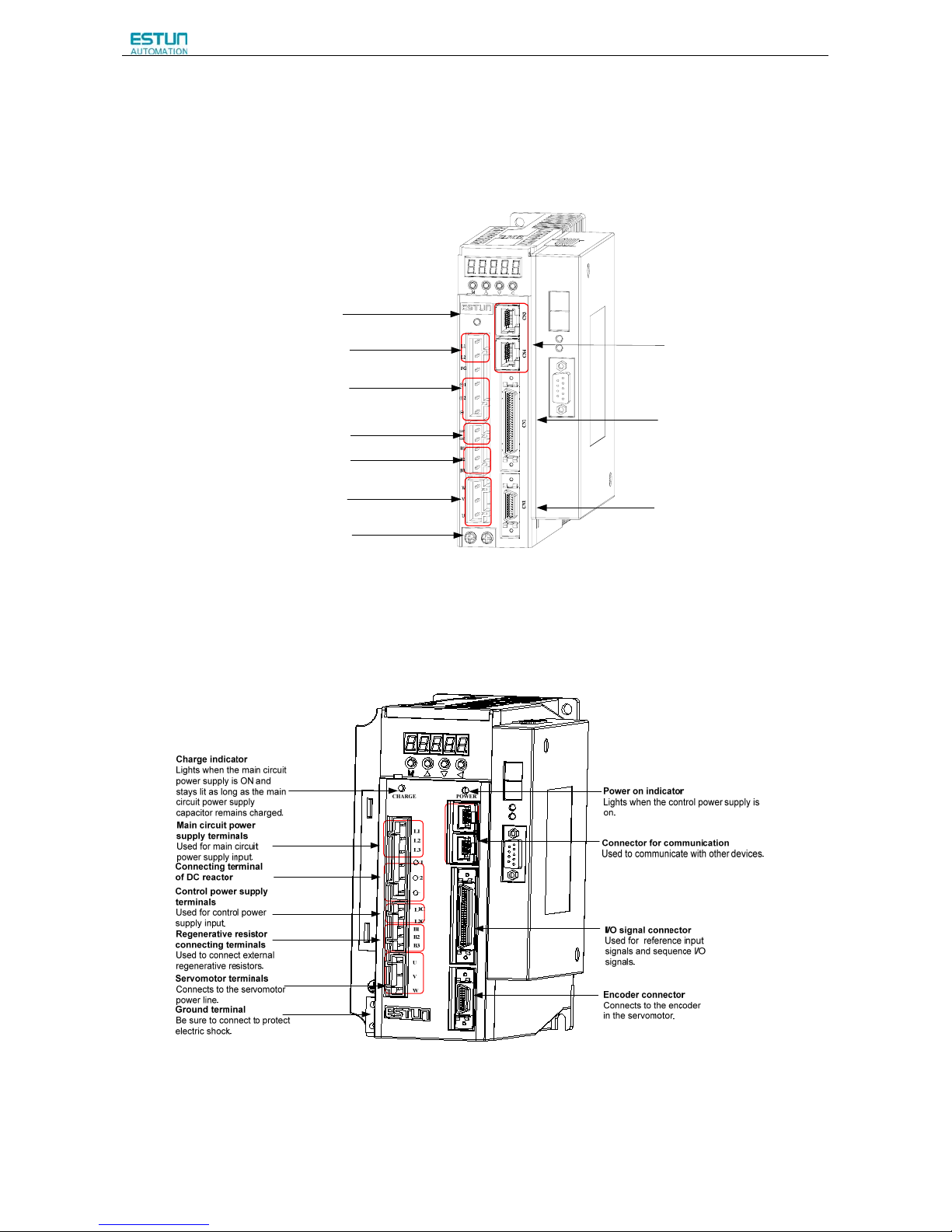
ProNet-02A/04A/ProNet-E-02A/04A
Charge indicator
Lights when the main circuit power supply is
ON and stays lit as long as the main circuit
power supply capacitor remains charged.
Ground terminal
Be sure to connect to protect electric shock.
Servomotor terminals
Connects to the servomotor power line.
Regenerative resistor connecting terminals
Used to connect external regenerative resistors.
Control power supply terminals
Used for control power supply input.
Connecting terminal of DC reactor
Main circuit power supply terminals
Used for main circuit power supply input.
Connector for communication
Used to communicate with other devices.
I/O signal connector
Used for reference input signals
and sequence I/O signals.
Encoder connector
Connects to the encoder in the
servomotor.
ProNet-08A/10A /ProNet-E-08A/10A
CN3
CN4
CN1
CN2
Page 19
ProNet Series AC Servo User's Manual
- 17 -
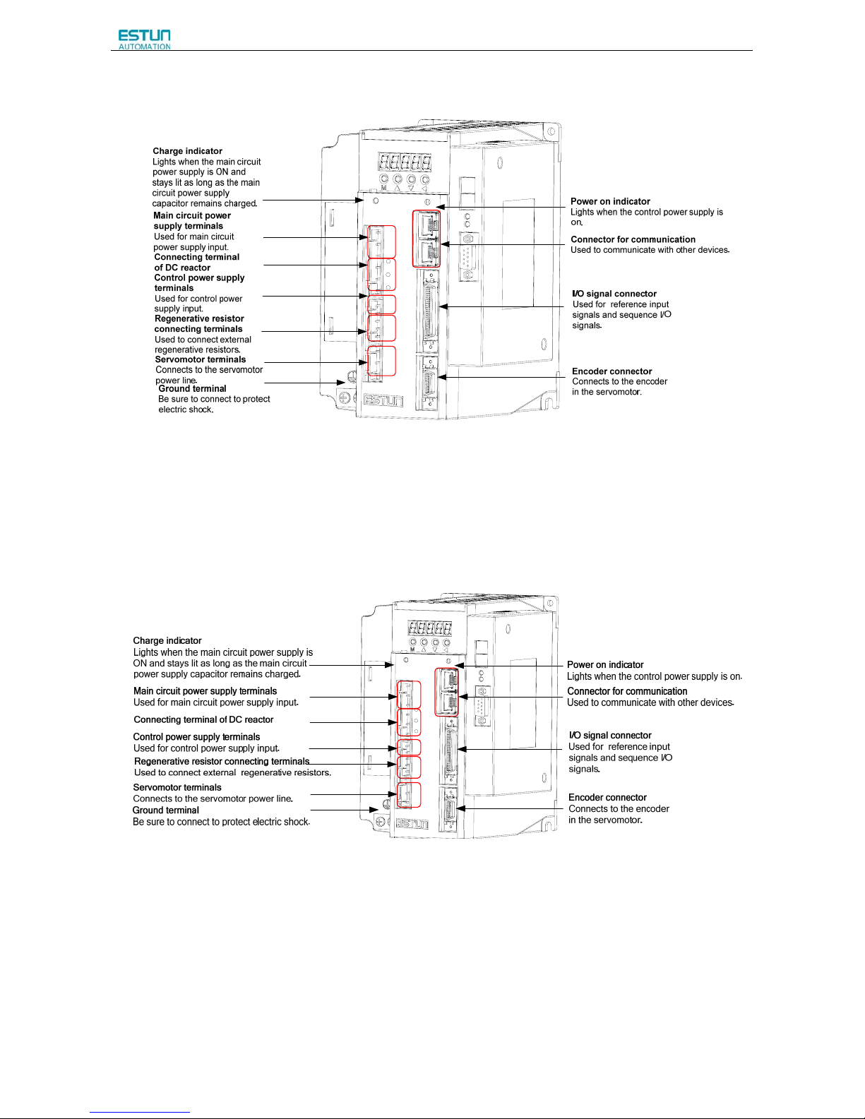
ProNet-15A/20A
/ ProNet-E-15A/20A
L1
L2
L3
CN3
CN4
CN1
CN2
L1C
L2C
B1
B2
B3
U
V
W
+
-
1
+
2
CHARGE
POWER
ProNet-10D/15D/20D/ProNet-E-10D/15D/20D
L1
L2
L3
CN3
CN4
CN1
CN2
24V
B1
B2
B3
U
V
W
+
-
1
+
2
CHARGE POWER
GND
Page 20
ProNet Series AC Servo User's Manual
- 18 -
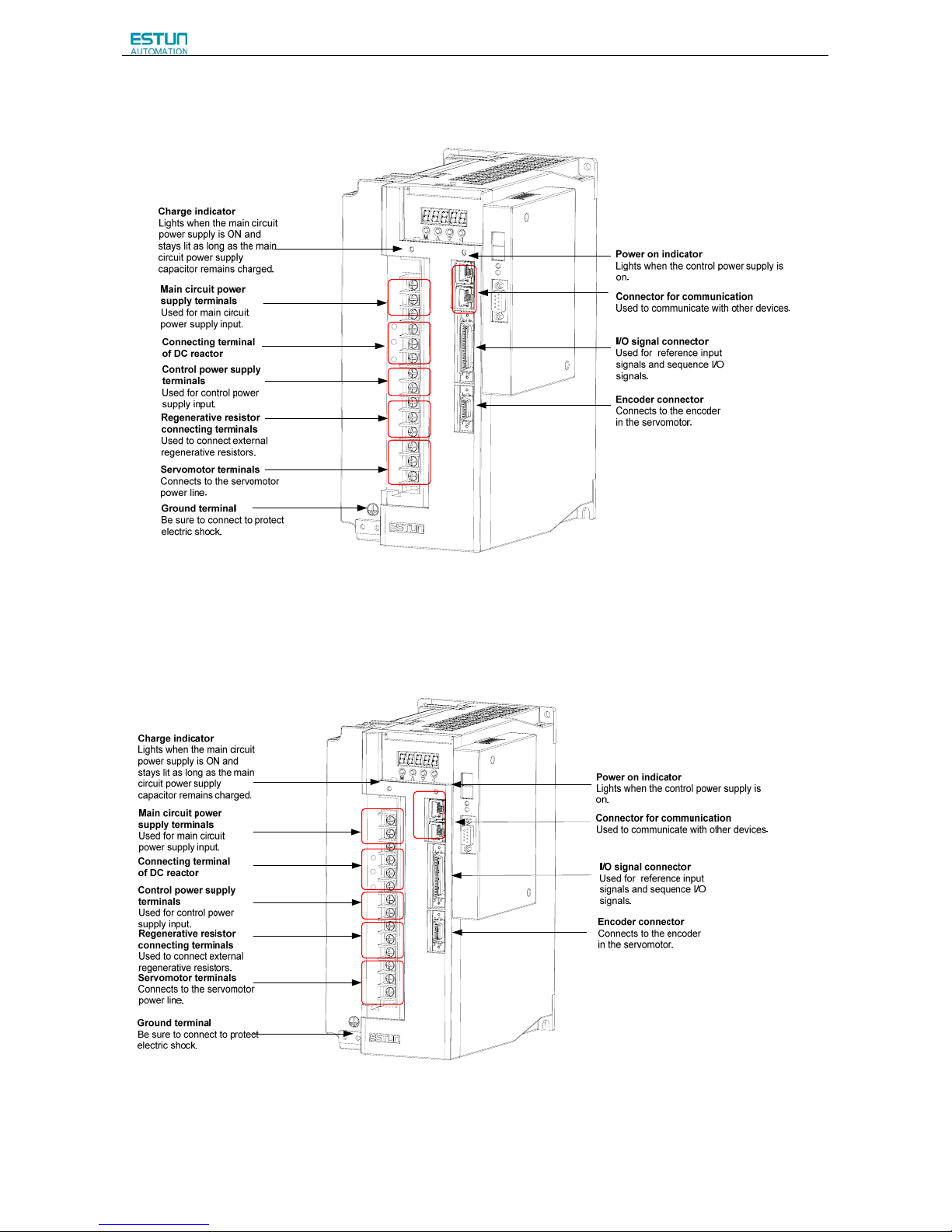
ProNet-30A/50A/ ProNet-E-30A/50A
CN3
CN4
CN1
CN2
CHARGE
POWER
L1
L2
L3
L1C
L2C
B1
B2
B3
U
V
W
+
-
1
+
2
ProNet-30D/50D/70D/75D/ ProNet-E-30D/50D
CN3
CN4
CN1
CN2
CHARGE
POWER
L1
L2
L3
24V
GND
B1
B2
B3
U
V
W
+
-
1
+
2
Page 21

ProNet Series AC Servo User's Manual
- 19 -
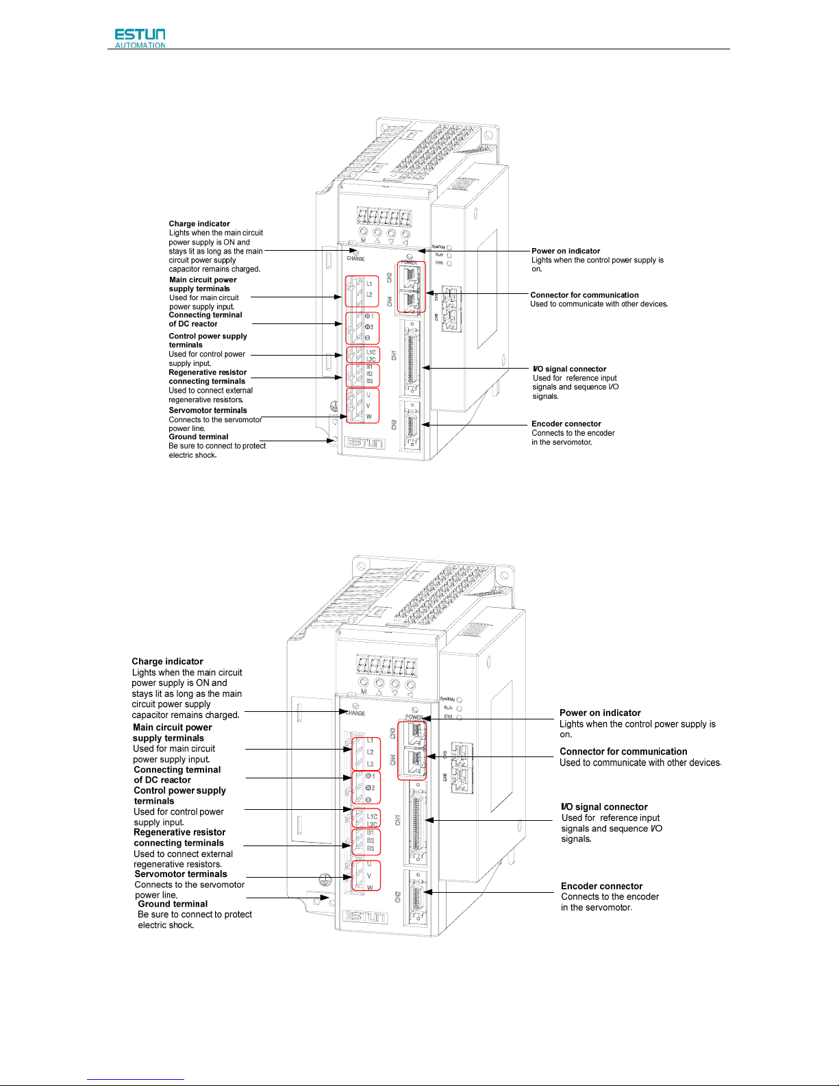
ProNet-1AD/1ED/2BD
ProNet-02B/ProNet-E-02B
Page 22
ProNet Series AC Servo User's Manual
- 20 -
ProNet-04B
/ProNet-E-04B
ProNet-08B /ProNet-E-08B
Page 23
ProNet Series AC Servo User's Manual
- 21 -
Chapter 2
Installation
2.1 Servomotor
Servomotor can be installed either horizontally or vertically. However, if the servomotor is installed incorrectly, the
service life of the servomotor will be shortened or unexpected problems may occur.
Please observe the installation instructions described below to install the servomotor correctly.
Before installation:
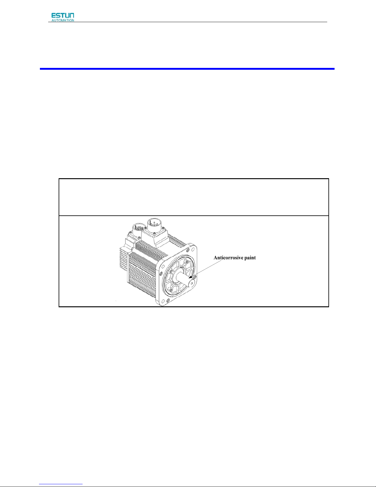
Anticorrosive paint is coated on the edge of the servomotor shaft. Clean off the anticorrosive paint thoroughly using
a cloth moistened with thinner.
Avoid getting thinner on other parts of the servomotor when cleaning the shaft.
2.1.1 Storage
When the servomotor is not being used, store it in an area with a temperature between -25℃ and 60℃ with the power
cable disconnected.
2.1.2 Installation Sites
The servomotor is designed for indoor use. Install the servomotor in an environment which meets the following
conditions.
z Free from corrosive and explosive gases.
z Well-ventilated and free from dust and moisture.
z Ambient temperature from 0 to 40℃.
z Relative humidity from 26% to 80%( non-condensing).
z Facilitates inspection and cleaning.
Page 24
ProNet Series AC Servo User's Manual
- 22 -
2.1.3 Installation Alignment
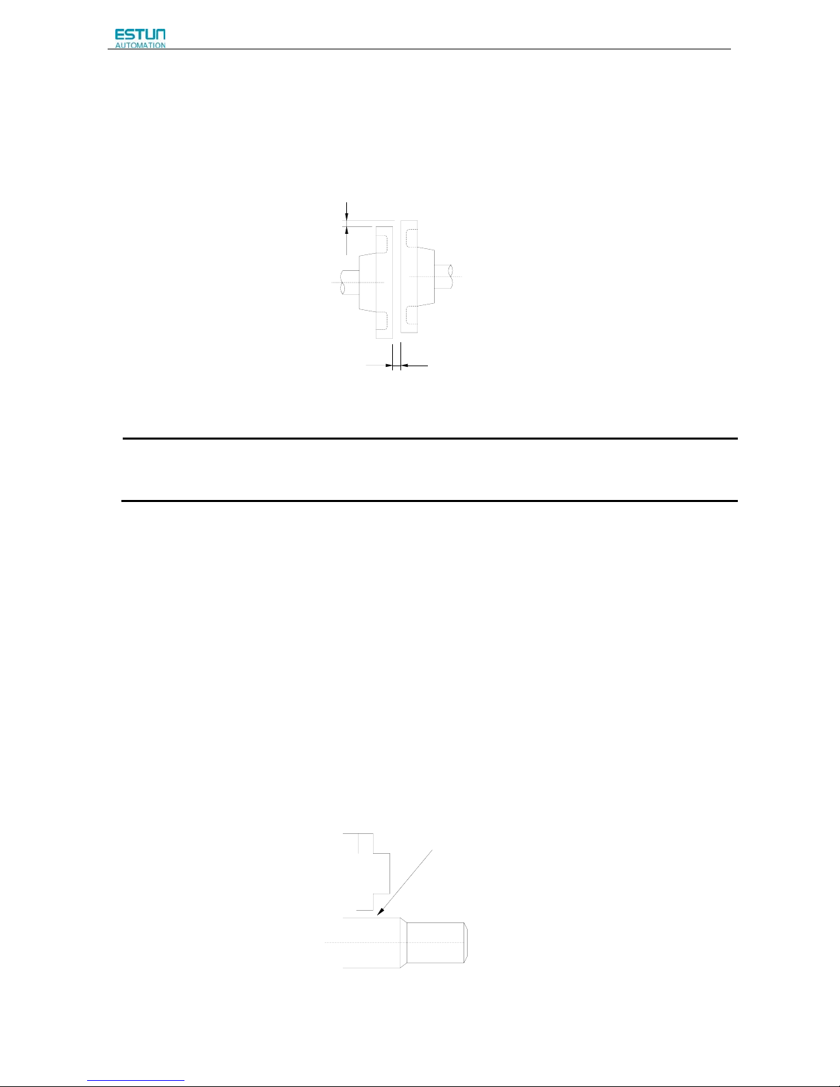
Align the shaft of the servomotor with that of the machinery shaft to be controlled. Then connect the two shafts with an
elastic coupling.
Install the servomotor so that alignment accurancy falls within the range shown below.
Measure this distance at four different positions in the circumference. The difference between the maximum and
minimum measurements must be 0.03mm or less.(Turn together with couplings.)
Note:
·If the alignment accurancy is incorrect , vibration will occur, resulting in damage to the bearings.
·Mechanical shock to the shaft end is forbidden, otherwise it may result in damage to the encoder of the servomotor.
2.1.4 Installation Orientation
Servomotor can be installed ethier horizontally or vertically.
2.1.5 Handling Oil and Water
If the servomotor is used in a location that is subject to water or oil drops, make sure of the servomotor protective
specification. If the servomotor is required to meet the protective specification to the through shaft section by default,
use a servomotor with an oil seal.
Through shaft section:
It refers to the gap where the shaft protrudes from the end of the servomotor.
Through Shaft Section
Page 25
ProNet Series AC Servo User's Manual
- 23 -
2.1.6 Cable Tension
When connecting the cables, the bending radius should not be too small, do not bend or apply tension to cables.
Since the conductor of a signal cable is very thin (0.2 mm or 0.3 mm), handle it with adequate care.
2.1.7 Install to the Client
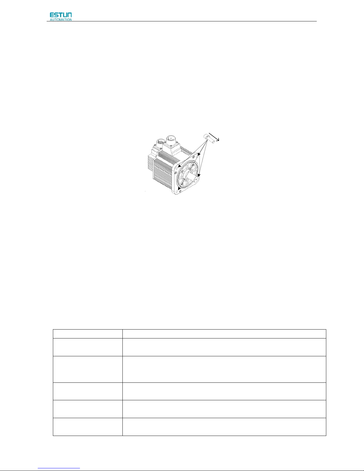
When the servo motor is mounted to the client, please firmly secure the servo motor by the screws with backing ring
as shown in the figure.
I
n
s
t
a
l
l
a
t
i
o
n
o
r
i
e
n
t
a
t
i
o
n
2.2 Servo Drive
ProNet series servo drive is a base-mounted type. Incorrect installation will cause problems. Always observe the
installation instructions described below.
2.2.1 Storage
When the servomotor is not being used, store it in an area with a temperature between -25℃ and 55℃ with the
power cable disconnected.
2.2.2 Installation Sites
Notes on installation are shown below.
Situation Notes on installation
When installed in a control
panel
Design the control panel size, unit layout, and cooling method so that the temperature
around the periphery of the servo drive does not exceed 55℃.
When installed near a
heating unit
Suppress radiation heat from the heating unit and a temperature rise caused by
convection so that the temperature around the periphery of the servo drive does not
exceed 55℃.
When installed near a
source of vibration
Install a vibration isolator underneath the servo drive to prevent it from receiving vibration.
When installed in a location
subject to corrosive gases
Take appropriate action to prevent corrosive gases. Corrosive gases do not immediately
affect the servo drive, but will eventually cause contactor-related devices to malfunction.
Others
Avoid installation in a hot and humid site or where excessive dust or iron powder is
present in the air.
Page 26
ProNet Series AC Servo User's Manual
- 24 -
2.2.3 Installation Orientation
Install the servo drive perpendicular to the wall as shown in the figure. The servo drive must be oriented this way
because it is designed to be cooled by natural convection or a cooling fan if required. Firmly secure the servo drive
through two mounting holes.
2.2.4 Installation Method
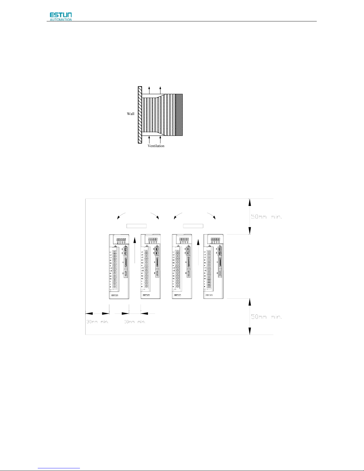
When installing multiple servo drives side by side in a control panel, observe the following installation method.
Colling Fan
Colling Fan
■Installation Orientation
Install servo drive perpendicular to the wall so that the front panel (containing connectors) faces outward.
■Cooling
Provide sufficient space around each servo drive to allow cooling by natural convection or fans.
■Installing side by side
When installing servo drives side by side, provide at least 10mm space between each individual servo drive and at
least 50mm space above and below each one as well as shown in the figure above. Ensure the temperature inside the
control panel is evenly distributed, and prevent the temperature around each servo drive from increasing excessively.
Cooling Fan Cooling Fan
Page 27

ProNet Series AC Servo User's Manual
- 25 -
Install cooling fans above the servo drives if necessary.
■Working conditions
1.Temperature:-20~ 55℃
2.Humidity:5%~95%RH
3.Vibration:4.9m/s
2
or less
4.Ambient temperature to ensure long-term reliability: 45 or less℃
5.Condensation and Freezing: None
Page 28
ProNet Series AC Servo User's Manual
- 26 -
Chapter 3
Wiring
3.1 Main Circuit Wiring
Please observe the following instructions while wiring the main circuit.
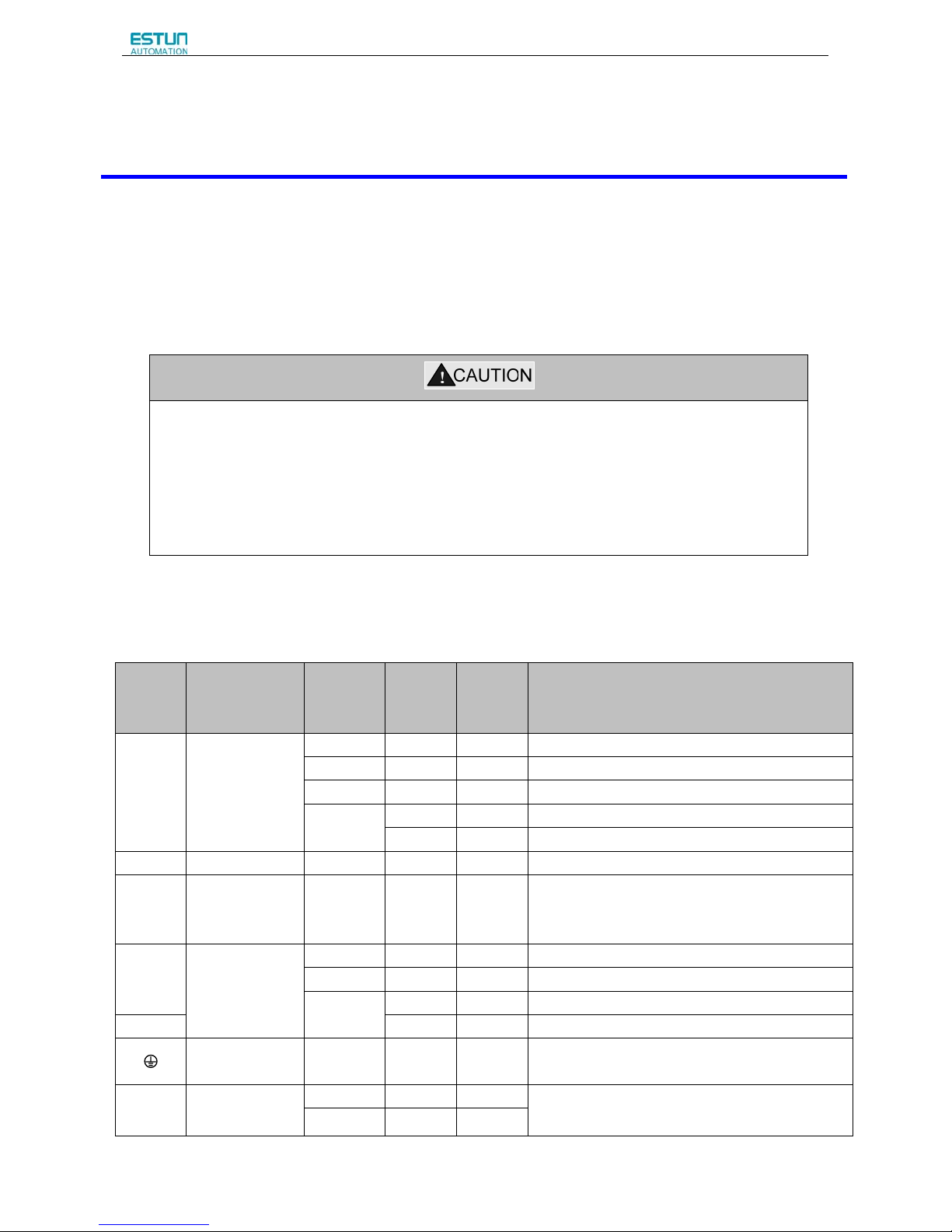
· Do not bundle or run power and signal lines together in the same duct. Keep power and signal lines
separated by at least 300 mm.
· Use twisted-pair shielded wires or multi-core twisted-pair shielded wires for signal and encoder feedback
lines.
· The maximum length is 3 m for reference input lines and 20 m for encoder feedback lines.
· Do not touch the power terminals for 5 minutes after turning power OFF because high voltage may still
remain in the servo drive.
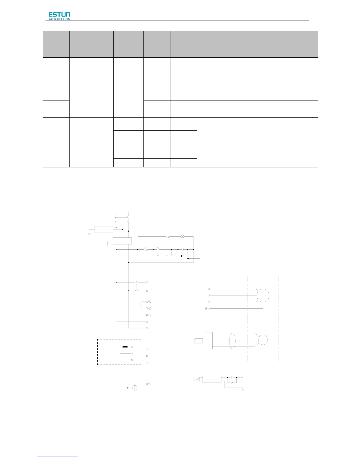
3.1.1 Names and Functions of Main Circuit Terminals
Terminal
Symbol
Name
Main
Circuit
Voltage(V)
Servo
Drive
Model
ProNet-
Servo
Drive
Model
Pronet-E-
Functions
L1,L2
Main circuit
power supply
input terminal
100
02B-08B 02B-08B
Single-phase 100~120VAC +10%~-15% (50/60Hz)
200 02A-04A 02A-04A
Single-phase 200~230VAC +10%~-15% (50/60Hz)
200 08A-50A 08A-50A
Three-phase 200~230VAC +10%~-15% (50/60Hz)
400
10D-75D 10D-50D Three-phase 380~480VAC +10%~-15% (50/60Hz)
1AD-2BD
-
Three-phase 380~440VAC +10%~-15% (50/60Hz)
FG FG 200 02A-04A 02A-04A Norma lly not connect ed.
U,V,W
Servomotor
connection
terminals
- - -
Connect to the servomotor.
L1C,L2C
Control circuit
power supply
input terminal
100
02B-08B 02B-08B
Single-phase 100~120VAC +10%~-15% (50/60Hz)
200 02A-50A 02A-50A
Single-phase 200~230VAC +10%~-15% (50/60Hz)
400
1AD-2BD
- Single-phase 380~440VAC +10%~-15% (50/60Hz)
24V,GND 10D-75D 10D-50D
24VDC +10%~-10%
Ground terminals
- - -
Connects to the power supply ground terminals and
servomotor ground terminal.
B1,B2,B3
External
regenerative
100
02B 02B
Connect an external regenerative resistor(provided
by customer) between B1 and B2.
200 02A-04A 02A-04A
Page 29
ProNet Series AC Servo User's Manual
- 27 -
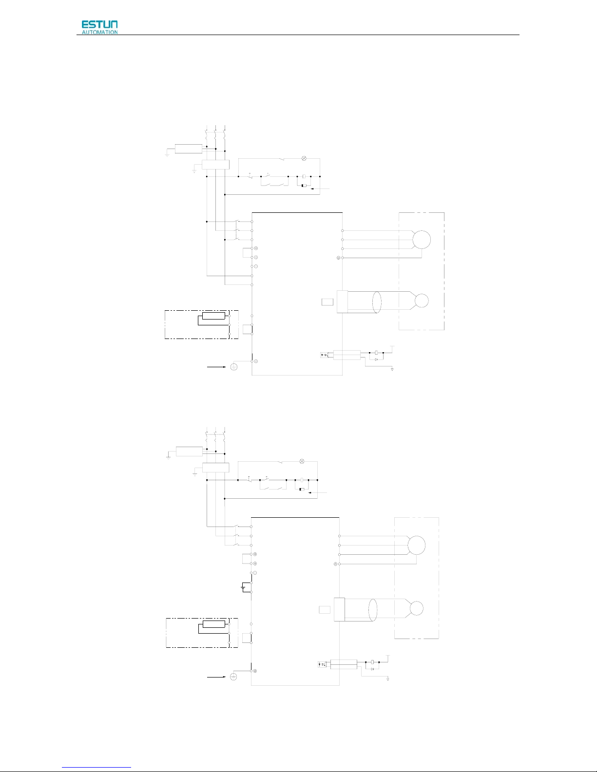
Terminal
Symbol
Name
Main
Circuit
Voltage(V)
Servo
Drive
Model
ProNet-
Servo
Drive
Model
Pronet-E-
Functions
resistor
connection
terminal
100
04B-08B 04B-08B
If using an internal regenerative resistor, please short
B2 and B3. Remove the wire between B2 and B3 and
connect an external regenerative resistor(provided
by customer) between B1 and B2, if the capacity of
the internal regenerative resistor is insufficient.
200 08A-50A 08A-50A
400
10D-75D 10D-50D
B1,B2 1AD-2BD
-
Connect an external regenerative resistor between
B1 and B2.
○
+ 1,○+ 2
DC reactor for
harmonic
suppression
terminal
200 02A-50A 02A-50A
Normally short ○+ 1and ○+2.
If a countermeasure against power supply harmonic
waves is needed, connect a DC reactor between ○+
1and ○+2.
400 10D-75D 10D-50D
○
-
Main circuit
minus terminal
200 02A-50A 02A-50A Norma lly not connect ed.
400 10D-75D 10D-50D
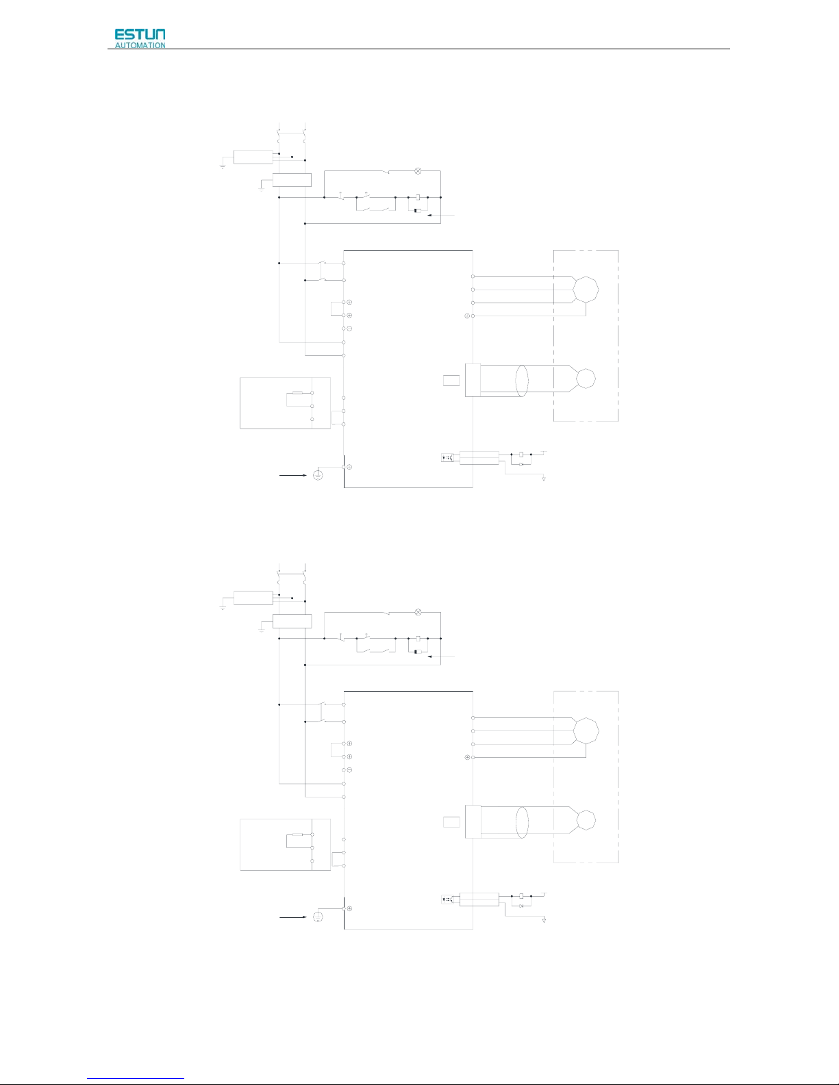
3.1.2 Typical Main Circuit Wiring Examples
Single-phase 200V ProNet-02A~04A/ Single-phase 200V ProNet-E-02A~04A
L1 L2
Single-phase 200~230V (50/60Hz)
+10%
-15%
Power OFF Pow er ON
1KM 1 SUP
1KM
1Ry
L1
L2
W
V
U
M
PG
A(1)
B(2)
C(3)
D(4)
L2C
L
1C
CN2
1Ry
1D
+24V
0V
1Ry
1PL (Servo Alarm Display)
ALM+7
ALM-
8
ProNet
Series Servodrive
1
2
Ground Terminal
Encoder
Servodrive
Magnetic Contactor
Molded-case Circuit Breaker
Surge Protector
Noise Filter
Be sure to connect a surge suppressor t o the
excitation coil of the magnetic contactor and relay.
B1
B2
B3
B1
B2
B3
External regenerator resistor
Note
1.The L1,L2,L3 and L1C,L2C terminals wiring method of ProNet-02A~04A/ProNet-E-02A~04A servo drives is different
from other ProNet series servo drives. Please note the specific terminal definition while wiring.
2.The main circuit power supply of ProNet-02A~04A/ProNet-E-02A~04A is Single-phase 200V
Page 30
ProNet Series AC Servo User's Manual
- 28 -
3. External regenerative resistor for ProNet-02A~04A/ProNet-E-02A~04A is provided by customer, the model of 60W,
50Ωresistor is recommended.
4.Change Pn521.0 from “1” to “0” when using the external regenerative resistor in ProNet-02A~04A/ProNet-E-02A~04A
servo drives.
·Three-phase 200V ProNet-08A~50A/ Three-phase 200V ProNet-E-08A~50A
Noise Filter
L1 L2 L3
Three-phase 200~230V (50/60Hz)
+10%
-15%
Power OFF Power ON
1KM 1SUP
1KM
1Ry
L1
L2
L3
W
V
U
M
PG
Servomotor
Encoder
A(1)
B(2)
C(3)
D(4)
L2C
L
1C
CN2
1Ry
1D
+24V
0V
Surge Protector
Magnetic Contactor
Molded-case Circuit Breaker
1Ry
1PL (Servo Alarm Display)
ALM+7
ALM-
8
Be sure to connect a surge suppressor to the
excitation coil of the magnetic contactor and relay.
.
ProNet
Series Servodrives
1
2
B1
B2
B3
B2
B1
External Regenerator Resistor
B3
Ground Terminal
Three-phase 400V ProNet-10D~75D
/ Three-phase 400V ProNet-E-10D~50D
Noise Filter
L1 L2 L3
Three-phase 380~440V (50/60Hz)
+10%
-15%
Power OFF Power ON
1KM 1SUP
1KM
1Ry
L1
L2
L3
W
V
U
M
PG
Servomotor
Encoder
A(1)
B(2)
C(3)
D(4)
CN2
1Ry
1D
+24V
0V
Surge Protector
Magnetic Contactor
Molded-case Circuit Breaker
1Ry
1PL (Servo Alarm Display)
ALM+7
ALM-
8
Be sure to connect a surge su ppressor to the
excitation coil of the magnetic contactor and relay.
.
ProNet
Series Servodrives
1
2
B1
B2
B3
B2
B1
External Regenerator Resistor
B3
Ground Terminal
GND
24V
24VDC Power Supply
Page 31

ProNet Series AC Servo User's Manual
- 29 -
Three-phase 400V ProNet-1AD~2BD
L1 L2 L3
Three-phase 380~440V ( 50/60Hz)
+10%
-15%
Power OFF Power ON
1KM 1SUP
1KM
1Ry
L1
L2
L3
W
V
U
M
PG
A(1)
B(2)
C(3)
D(4)
L2C
L
1C
CN2
1Ry
1D
+24V
0V
1Ry
1PL (Servo Alarm Display)
ALM+7
ALM-8
ProNet
Series Servodrive
B1
B2
External Regenerative Res istor
Ground Terminal
Encoder
Servodrive
Molded-case Circuit Break er
Surge Protector
Be sure to connect a sur ge
suppressor to the excitation coil of
the magnetic contactor and relay.
Magnetic Contactor
Noise Filter
Notes:
1. A resistor value of 1500W/20Ω is recommended for the external regenerative resistor of ProNet-1AD.
2. A resistor value of 1500W/15Ω is recommended for the external regenerative resistor of ProNet-1ED.
3. A resistor value of 1500W/20Ω is recommended for the external regenerative resistor of ProNet-2BD.
Single-phase 100V ProNet-02B /Single-phase 100V ProNet-E-02B
L1 L2
Single-phase 100~120V (50/60Hz)
+10%
-15%
Power OFF Power ON
1KM 1SUP
1KM
1Ry
L1
L2
W
V
U
M
PG
A(1)
B(2)
C(3)
D(4)
L2C
L
1C
CN2
1Ry
1D
+24V
0V
1Ry
1PL (Servo Alarm Display)
ALM+7
ALM-8
1
2
Ground Terminal
Encoder
Servodrive
Magnetic Contactor
Molded-case Circuit Breaker
Surge Protector
Nois e Filter
Be sure to connect a surge supp ressor to the
excitation coil of the magnetic contactor and relay.
B1
B2
B3
B1
B2
B3
Exter nal rege nerato r resistor
Page 32
ProNet Series AC Servo User's Manual
- 30 -
Single-phase 100V ProNet-04B /Single-phase 100V ProNet-E-04B
L1 L2
Single-phase 100~120V (50/60Hz)
+10%
-15%
Power OFF Power ON
1KM 1SUP
1KM
1Ry
L1
L2
W
V
U
M
PG
A(1)
B(2)
C(3)
D(4)
L2C
L
1C
CN2
1Ry
1D
+24V
0V
1Ry
1PL (Servo Alarm Display)
ALM+7
ALM-8
1
2
Ground Terminal
Encoder
Servodrive
Magnetic Contactor
Molded-case Circuit Breaker
Surge Protector
Noise Filter
Be sure to connect a surge suppressor to the
excitation coil of the magnetic contactor and relay.
B1
B2
B3
B1
B2
B3
External regenerator resistor
Single-phase 100V ProNet-08B /Single-phase 100V ProNet-E-08B
L1 L2
Single-phase 100~120V (50/60Hz)
+10%
-15%
Power OFF Power ON
1KM 1SUP
1KM
1Ry
L1
L2
W
V
U
M
PG
A(1)
B(2)
C(3)
D(4)
L2C
L
1C
CN2
1Ry
1D
+24V
0V
1Ry
1PL (Servo Alarm Display)
ALM+7
ALM-8
1
2
Ground Terminal
Encoder
Servodrive
Magnetic Contactor
Molded-case Circuit Breaker
Surge Protector
Noise Filter
Be sure to connect a surge suppressor to the
excitation coil of the magnetic contactor and relay.
B1
B2
B3
B1
B2
B3
External regenerator resistor
Notes:
When single-phase 100VAC is provided for main circuit on rated speed, instantaneous peak torque≤4.78 N.m.
When three-phase 100VAC is provided for main circuit on rated speed, instantaneous peak torque≤7.16 N.m.
Page 33
ProNet Series AC Servo User's Manual
- 31 -
3.2 I/O Signals
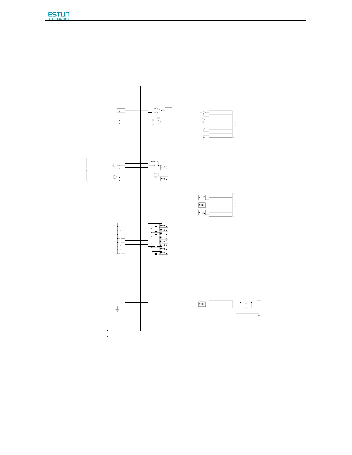
3.2.1 Examples of I/O Signal Connections
+
A/D
2K
Ω
150Ω
150Ω
2KΩ
PULS / CW / A
SIGN / CCW / B
Connect Shield to Connector Shell
Open-Collector Reference
Use
Speed Reference(±0~10V/Rated Speed)
Torque Reference(±0~10V/Rated Torque)
Position Reference
Signal Allocations can be Modified:
S-ON: Servo ON
P-CON: Proportion Control
P-OT:Forward Run Prohibited
N-OT:Reverse Run Prohibited
ALM-RST: Alarm Reset
CLR: Clear Error Pulse
P-CL:Forward Torque Limit
N-CL:Reverse Torque Limit
SHOM: Home
ORG: Zero Position
+24V
PP P P
PG Divided Ratio Output
Applicable Line Output
AM26LS32A Manufactured by TI or the Equivalent.
Signal Allocati ons can be Modified:
V-CMP: Speed Coincidence
COIN: Positioning Completion
TGON:Rotation Detection
S-RDY:Servo Ready
CLT:Torque Limit Detection
BK:Brake Interlock
PGC: Encoder C-Pulse Output
OT: Over Travel
RD: Servo Enabled Motor Excitation Output
HOME: Home Completion Output
P
Represents Twisted-pair Wires
ALM: Servo Alarm Output
Photocoupler Output:
Maximum Operati ng Voltage:DC30V
Maximum Output Current:DC50mA
-
-
+
ref
ref
40K
10K
40K
10K
1Ry
1D
+24V
0V
PAO+
20
PAO-21
PBO+22
PBO-23
PCO+24
PCO-25
DGND50
TGON+
5
TGON-
6
S-RDY+
9
S-RDY-10
V-CMP+11
V-CMP-12
ALM+7
ALM-8
VREF+ 1
VREF- 2
TREF+ 26
TREF- 27
PPI 34
PULS+ 30
PULS-
31
SIGN+ 32
SIGN- 33
DICOM
13
S-ON 14
P-CON 15
P-OT 16
N-OT 17
ALM-RST
39
CLR 40
P-CL 41
N-CL 42
Shield
ProNet
Series Servodrive
3.3KΩ
Page 34

ProNet Series AC Servo User's Manual
- 32 -
3.2.2 I/O Signal Names and Functions
Input Signals
Control
Mode
Signal
Name
Pin
No.
Function
Speed
Position
Torque
/S-ON 14 Servo ON: Turns the servomotor on.
/P-CON 15
Function selected by parameter.
Proportional
control reference
Switches the speed control loop from PI to P control when
ON.
Direction
reference
With the internally set speed selection: Switch the rotation
direction.
Control mode
switching
Enables control mode switching.
Zero-clamp
reference
Speed control with zero-clamp function: Reference speed is
zero when ON.
Reference pulse
block
Position control with reference pulse: Stops reference pulse
input when ON.
P-OT
N-OT
16
17
Forward run
prohibited
Reverse run
prohibited
Overtravel prohibited: Stops servomotor when OFF.
/PCL
/NCL
41
42
Function selected by parameter.
Forward external
torque limit ON
Reverse external
torque limit ON
Current limit function enabled when ON.
Internal speed
switching
With the internally set speed selection: Switches the internal
speed settings.
/ALM-RST 39 Alarm reset: Releases the servo alarm state.
DICOM 13 Control power supply input for I/O signals: Provide the +24V DC power supply
Speed
VREF+ 1
Speed reference input: ±10V.
VREF- 2
Position
PULS+ 30
Pulse reference input mode:
Sign + pulse train
CCW + CW pulse
Two-phase pulse (90º phase differential)
PULS- 31
SIGN+ 32
SIGN- 33
PPI 34
Power supply input for open collector reference (2KΩ/0.5W resistor is built into the
servo drive).
/CLR 40
Positional error pulse clear input: Clear the positional error pulse during position
control.
SHOM - Homing trigger signal(effective at the rising edge),allocated by Pn509 or Pn510
ORG - Zero Position(effective at high level), allocated by Pn509 or Pn510
Torque
T-REF+ 26
Torque reference input: ±10V.
T-REF- 27
Page 35

ProNet Series AC Servo User's Manual
- 33 -
Output signals
Control
Mode
Signal
Name
Pin No. Function
Speed
Position
Torque
/TGON+ 5
Detects when the servomotor is rotating at a speed higher than the motor
speed seeting.
/TGON- 6
ALM+ 7
Servo alarm:
Turns off when an error is detected.
ALM- 8
/S-RDY+ 9 Servo ready:
ON if there is no servo alarm when the control/main circuit power supply
is turned ON.
/S-RDY- 10
PAO+ 20
Phase-A signal
Converted two-phase pulse(phases A and B)
encoder output.
PAO- 21
PBO+ 22
Phase-B signal
PBO- 23
PCO+ 24
Phase-C signal Zero-point pulse(Phase-C) signal
PCO- 25
FG Shell
Connect frame to ground if the shield wire of the
I/O signal cable is connected to the connector shell.
Speed
/V-CMP+ 11
Speed coincidence:
Detects whether the motor speed is within the setting range and if it
matches the reference speed value.
/V-CMP- 12
Position
/COIN+ 11
Positioning completion:
Turns ON when the number of positional error pulses reaches the value
set. The setting is the number of positional error pulses set in the
reference units.
/COIN- 12
Reserved
/CLT
—
Reserved terminals:
The functions allocated to /TGON, /S-RDY, and /V-CMP (/COIN) can be
changed by using the parameters.
/CLT: Torque limit output
Turns on when it reaches the value set.
/BK: Brake interlock output
Releases the brake when ON,
/PGC:C pulse output
OT:Over travel signal output
/RD:Servo enabled motor excitation output
/HOME: Home completion output
/BK
—
4,18,19,29,35
36,37,38,43
44,45,47,49
Not used.
Page 36
ProNet Series AC Servo User's Manual
- 34 -
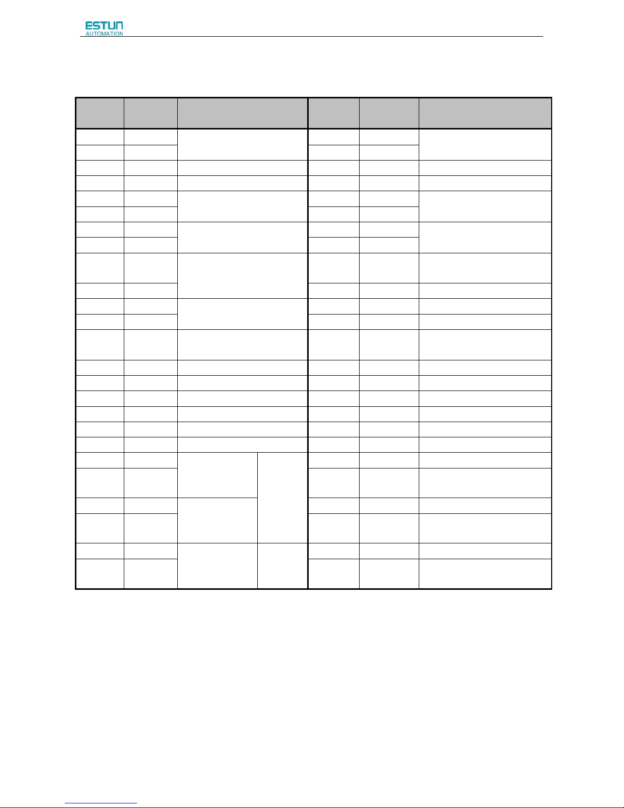
3.2.3 I/O Signal Connector (CN1) Terminal Layout
Terminal
No.
Name Function
Terminal
No.
Name Function
1 VREF+
Speed reference input:±10V
26 T-REF+
Torque referenceinput:±10V
2 VREF- 27 T-REF-
3 DGND DGND 28 DGND DGND
4 — Reserved 29 — Reserved
5 /TGON+
Running signal output
30 PULS+
Reference pulse input
6 /TGON- 31 PULS-
7 ALM+
Servo alarm
32 SIGN+
Reference sign input
8 ALM- 33 SIGN-
9 /S-RDY+
Servo ready
34 PPI
Open collector reference
power supply
10 /S-RDY- 35 — Reserved
11 /COIN+
Positioning completion
36 — Reserved
12 /COIN- 37 — Reserved
13 DICOM
I/O signal power supply 24V
DC
38 — Reserved
14 /S-ON Servo ON 39 /ALM-RST Alarm reset
15 /P-CON P/PI control input 40 /CLR Position error pulse clear input
16 P-OT Forward run prohibited 41 /PCL Forward torque limit input
17 N-OT Reverse run prohibited 42 /NCL Reverse torque limit input
18 — Reserved 43 — Reserved
19 — Reserved 44 — Reserved
20 PAO+ PG dividing
pulse output
phase A
PG
dividing
pulse
output
45 — Reserved
21 PAO- 46 DGND DGND
22 PBO+ PG dividing
pulse output
phase B
47 — Reserved
23 PBO- 48 DGND DGND
24 PCO+ PG dividing
pulse output
phase C
Zero-point
pulse
49 — Reserved
25 PCO- 50 DGND DGND
Note: The functions allocated to the following input and output signals can be changed by using the parameters.
·Input signals: /S-ON,/P-CON,P-OT,N-OT,/ALM-RST,/CLR,/PCL,/NCL,SHOM,ORG
·Output signals: /TGON,/S-RDY,/COIN,/HOME
Please refer to A.3 Parameters in details for detailed information.
Page 37
ProNet Series AC Servo User's Manual
- 35 -
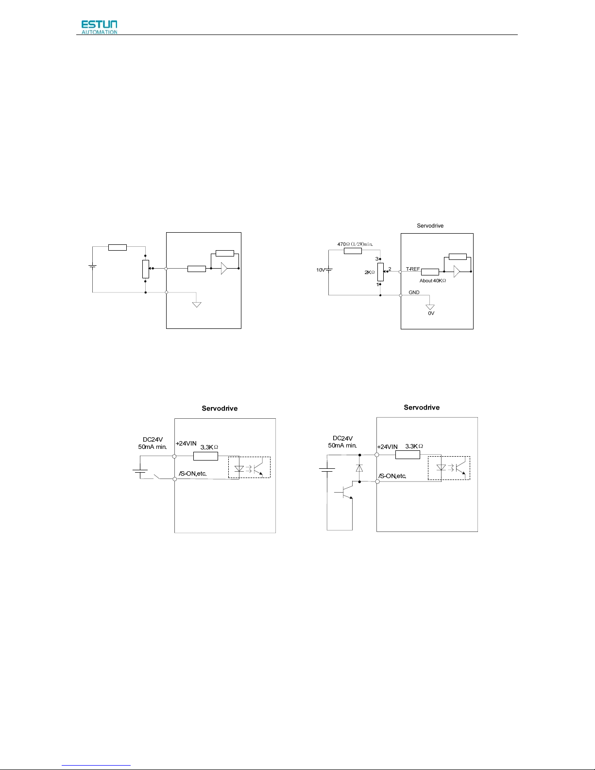
3.2.4 Interface Circuit
This section shows examples of servo drive I/O signal connection to the host controller.
■Interface for Analog Reference Input Circuit
Analog signals are either speed or torque reference signals at about 40kΩ impedance, and the maximum allowable
voltages for input signals is ±10V.
Reference speed input Reference torque input
10V
470Ω(1/2W)min.
1
2
3
2KΩ
V-REF
GND
About 40KΩ
0V
Servodrive
■Interface for sequence input circuit
The sequence input circuit interface connects through a relay or open-collector transistor circuit. Select a low-current relay
otherwise a faulty contact will result.
■Interface for line driver output circuit
The amount of two-phase (phase A and phase B) pulse output signals (PAO,/PAO,PBO,/PBO) and zero-point pulse
signals (PCO,/PCO) are output via line-driver output circuits. Normally, the servo drive uses this output circuit in speed
control to comprise the position control system at the host controller. Connect the line-driver output circuit through a line
receiver circuit at the host controller.
■Interface for sequence output circuit
Photocoupler output circuits are used for Servo Alarm (ALM), Servo Ready(S-RDY), and other sequence output signal
circuits. Connect a photocoupler output circuit through a relay circuit.
Page 38
ProNet Series AC Servo User's Manual
- 36 -
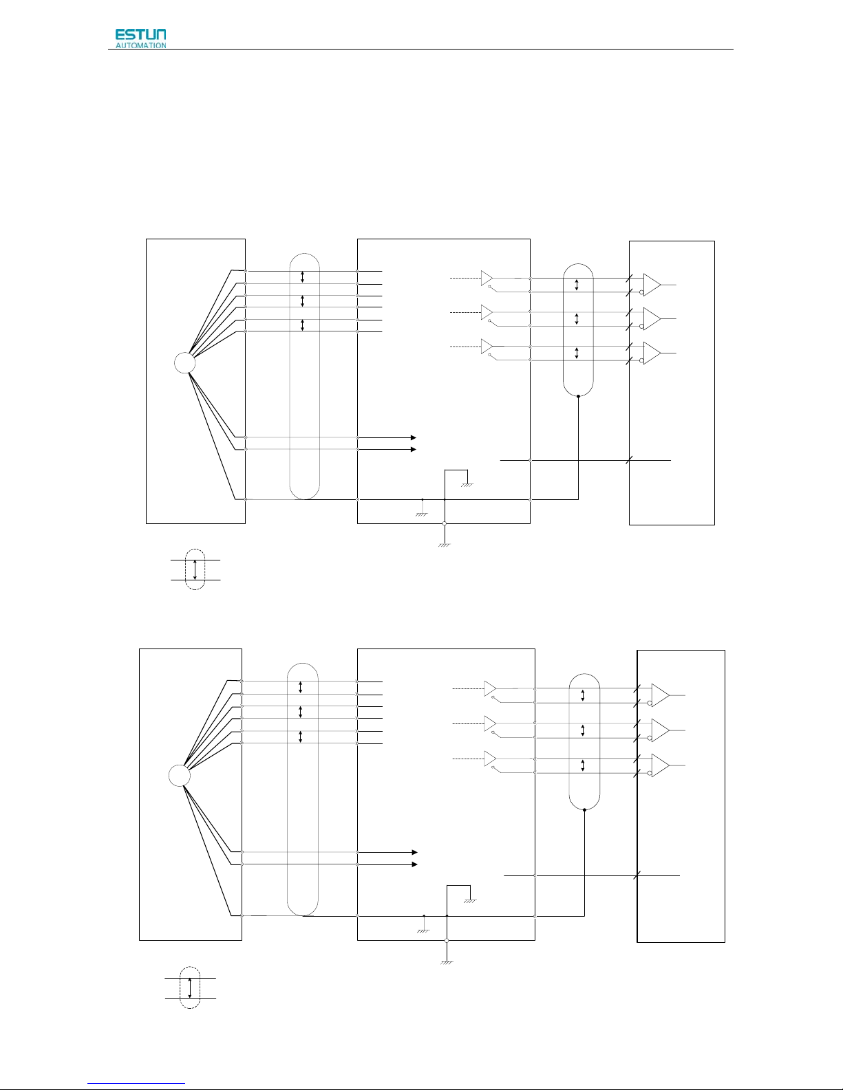
3.3 Wiring Encoders
3.3.1 Connecting an Encoder(CN2)
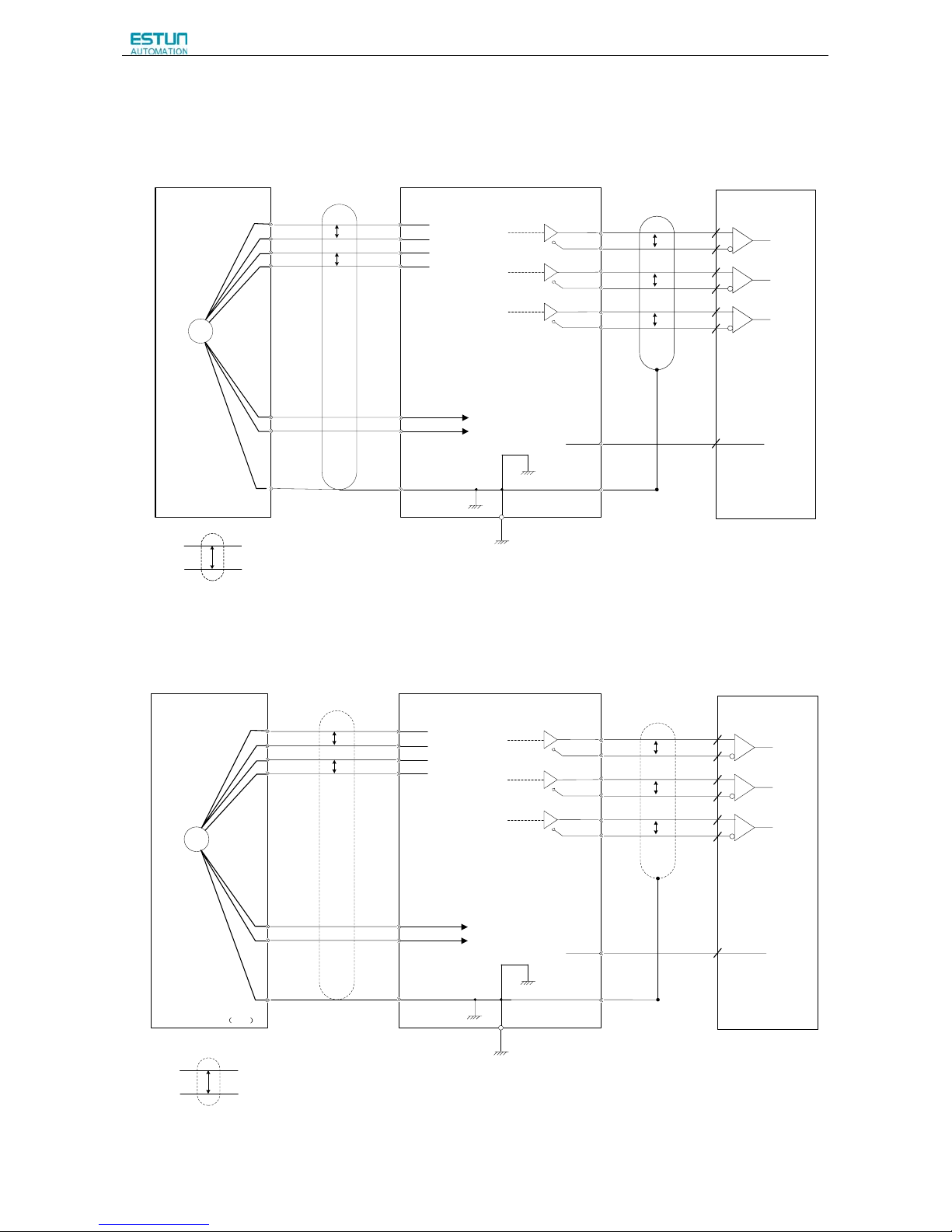
■ Wire-saving Incremental Encoder(2500P/R)(Waterproof)
Wire-saving Incremental
Encoder
Servodrive
PG
1(A)
2(B)
3(C)
4(D)
5(E)
6(F)
PA
/PA
PB
/PB
PC
/PC
7(H)
8(G)
PAO
/PAO
20
21
P
P
P
P
*
*
PG5V
PG0V
P
*
1CN
2CN
2-1
2-2
2-3
2-4
2-5
2-6
2-7、2-8、2-9
2-17、2-18、2-19
FG
PBO
/PBO
22
23
P
PCO
/PCO
24
25
P
0V
SG
0V
1-18
1-36
9(J)
Output line driver
AM26LS31 manufactured
by TI or the equivalent.
shielded wires
Connector shell
Connector shell
(Shell)
Applicable linereceiver SN75175
manufactured by TI
or the equivalent.
Host controller
Represents multi-core twisted pair shielded wires.
Phase-A
Phase-B
Phase-C
■ Wire-saving Incremental Encoder(2500P/R)(Standard)
PG
1(A)
4(B)
2(C)
5(D)
3(E)
6(F)
PA
/PA
PB
/PB
PC
/PC
7(H)
8(G)
PAO
/PAO
20
21
P
P
P
P
*
*
PG5V
PG0V
P
*
1CN
2CN
2-1
2-2
2-3
2-4
2-5
2-6
2-7、2-8、2-9
2-17、2-18、2-19
FG
PBO
/PBO
22
23
P
PCO
/PCO
24
25
P
0V
SG
0V
1-18
1-36
9(J)
Wire-saving Incremental
Encoder
Servodrive
Host controller
Represents mul ti-core twisted pair shie l ded wires.
Phase-A
Phase-B
Phase-C
Output line driver
AM26LS31 manufactured
by TI or the equivalent.
Applicable linereceiver SN75175
manufactured by TI
or the equivalent.
shielded wires
Connector shell
Connector shell
(Shell)
Page 39
ProNet Series AC Servo User's Manual
- 37 -
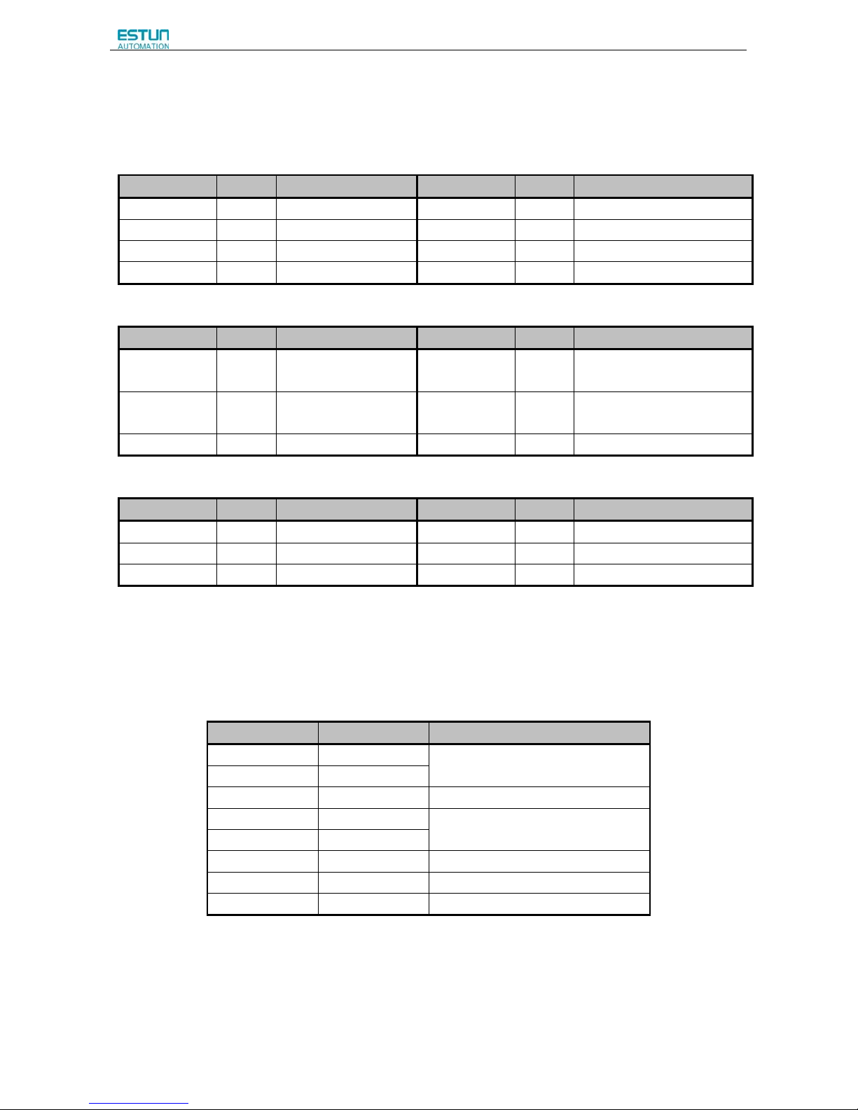
17 bit Incremental/Absolute Encoders
Incremental/Absolute Encoders
Servodrive
PG
K(1)
L(2)
T(3)
S(4)
PS
/PS
BAT+
BAT-
H(5)
G(6)
PAO
/PAO
20
21
P
P
P
*
*
PG5V
PG0V
Connector shell
Connector shellshielded wires
P
Represents multi-core twisted pair shielded wires.
*
Phase-A
Output line driver
AM26LS31 manufactured
by TI or the equivalent.
CN1
CN2
7
8
17
18
9
19
FG
Applicable linereceiver SN75175
manufactured by TI
or the equivalent.
PBO
/PBO
22
23
P
Phase-B
PCO
/PCO
24
25
P
Phase-C
0V
DGND
0V
50
(Shell)
Note: (1)BAT+ and B AT- signals are not used when using an incremental encoder .
(2)The pin numbers for the connector wiring differ depending on the servomotors .
Host controller
J(7)
Resolver
Resolver
Servodrive
PG
K
L
T
S
SIN+
SIN-
COS+
COS-
H
G
PAO
/PAO
20
21
P
P
P
*
*
R1
R2
Connect shell
Connector shell
shielded wires
P
Represents multi-core twisted pair shielded wires.*
Phase-A
Output line-driver
AM26LS31
manufactured by TI
or equivalent.
CN1
CN2
7
8
17
18
9
19
FG
Applicable linereceiver SN75175
manufactured by
TI or equivalent.
PBO
/PBO
22
23
P
Phase-B
PCO
/PCO
24
25
P
Phase-C
0V
DGND
0V
50
Shell
Host controller
J
Page 40
ProNet Series AC Servo User's Manual
- 38 -
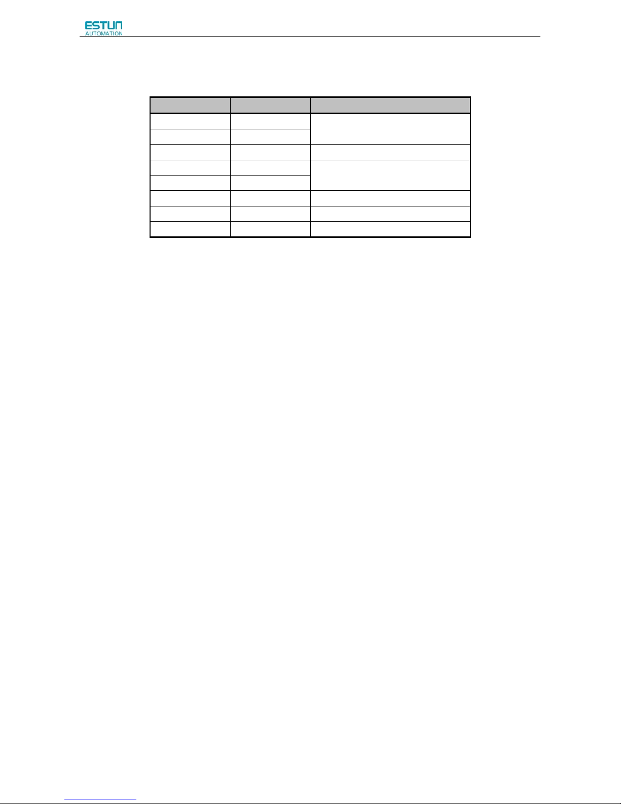
3.3.2 Encoder Connector(CN2) Terminal Layout
Wire-saving Incremental Encoder(2500P/R)
Terminal No. Name Function Terminal No. Name Function
1 PA
PG input phase A
5 PC
PG input phase B
2 /PA
PG input phase /A
6 /PC
PG input phase /B
3 PB
PG input phase B
7,8,9 PG5V
PG power supply +5V
4 /PB
PG input phase /B
17,18,19 SG
PG power supply 0V
17 Bit Incremental/ Absolute Encoder
Terminal No. Name Function Terminal No. Name Function
7 PS PG serial signal input 17 BAT+
Battery(+)
(For an absolute encoder)
8 /PS PG serial signal input 18 BAT-
Battery(-)
(For an absolute encoder)
9 PG5V PG power supply +5V 19 GND PG power supply 0V
Resolver
Terminal No. Name Function Terminal No. Name Function
7 SIN+ Differential Sine Signal 17 COS+ Differential Cosine Signal
8 SIN- Differential Sine Signal 18 COS- Differential Cosine Signal
9 R1 Excitation signal 19 R2 Excitation Signal
3.4 Communication Connection
3.4.1 Communication Connector(CN3) Terminal Layout
Terminal No. Name Function
1 —
Reserved
2 —
3 485+ RS-485 communication terminal
4 ISO_GND
Isolated ground
5 ISO_GND
6 485- RS-485 communication terminal
7 CANH CAN communication terminal
8 CANL CAN communication terminal
Note: Do not short terminal 1 and 2 of CN3.
Page 41
ProNet Series AC Servo User's Manual
- 39 -
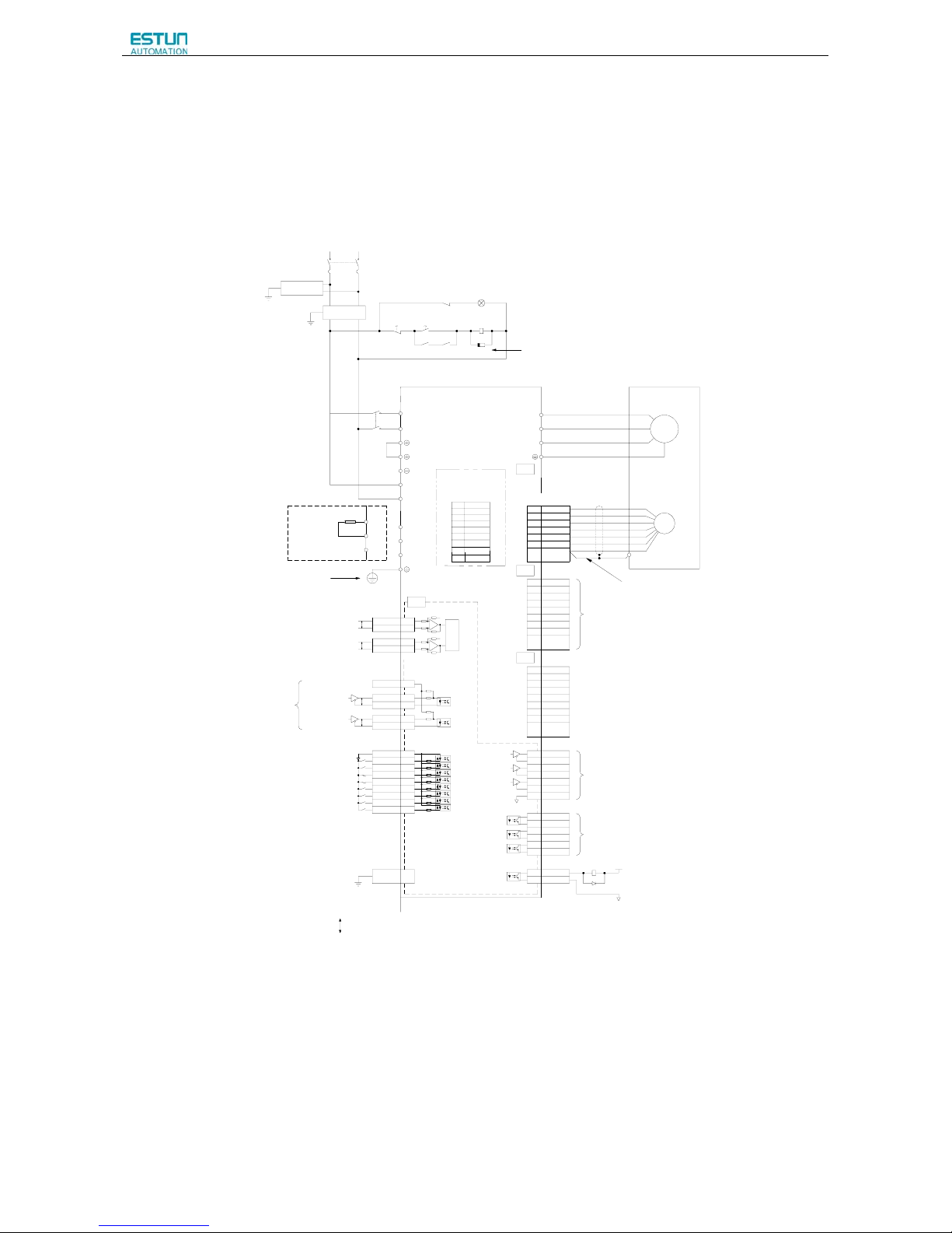
3.4.2 Communication Connector(CN4) Terminal Layout
Terminal No. Name Function
1 —
Reserved
2 —
3 485+ RS-485 communication terminal
4 ISO_GND
Isolated ground
5 ISO_GND
6 485- RS-485 communication terminal
7 CANH CAN communication terminal
8 CANL CAN communication terminal
Page 42
ProNet Series AC Servo User's Manual
- 40 -
3.5 Standard Wiring Examples
3.5.1 Single-phase 200V ProNet-02A~04A/ProNet-E-02A~04A
Noise Filter
L1 L2
single-phase 200~230V (50/60Hz)
+10%
-15%
Power OFF Power ON
1KM 1SUP
1KM
1Ry
L1
L2
1
2
W
V
U
M
PG
Servomotor
Encoder
A(1)
B(2)
C(3)
D(4)
L2C
L
1C
+
A/D
CN1
CN2
2KΩ
150Ω
150Ω
2KΩ
PULS / CW / A
SIGN / CCW / B
Connect Shield t o Connector Shell.
ProNet
Series Servodrives
Open-collector Reference Use
Speed Ref erence(±0 ~10V/Rated Speed)
Torque Referenc e (±0~10 V / Rated Torque)
Position Reference
Signal allocatons can be modified:
S-ON: Servo ON
P-CON: P Control
P-OT: Forward Run Prohibited
N-OT: Reverse Run Prohibited
ALM-RST: Alarm Reset
CLR: Cl ear Error P ulse
P-CL: Forward Torque Limit
N-CL: Reverse Torque Limit
SHOM: Home
ORG: Zero Position
+24V
PP P P
PG Divided Rati o Output:
Applicable Line Receiver
AM26LS32A Ma nufactured by TI or the Equivalent.
P
Represents Twis ted-pair Wires
-
-
+
ref
ref
40K
10K
40K
10K
CN3
CN4
Use special communication cable to connect
PC(Personal Computer).
1Ry
1D
+24V
0V
Surge Protector
Magnetic Contactor
Molded-case Circuit Breaker
1Ry
1PL (Servo Alarm Display)
1
2
485+3
ISO_GND
4
ISO_GND
5
485-6
CANH7
CANL8
N.C.1
N.C.2
485+3
ISO_GND
4
ISO_GND
5
485-6
CANH7
CANL8
PAO+20
PAO-21
PBO+22
PBO-23
PCO+24
PCO-
25
DGND
50
TGON+5
TGON-6
S-RDY+9
S-RDY-
10
V-CMP+11
V-CMP-12
ALM+7
ALM-
8
VREF+ 1
VREF- 2
TREF+ 26
TREF- 27
PPI 34
PULS+ 30
PULS-
31
SIGN+ 32
SIGN- 33
DICOM 13
S-ON 14
P-CON 15
P-OT 16
N-OT 17
ALM-RST
39
CLR
40
P-CL 41
N-CL 42
Shield
Shell
S+7
S-8
BAT+17
BAT-
18
PG5V9
PG0V19
Shield
Serial Encoder
Shell
Shield
Shell
Shield
Shell
Be sure to connect a surge suppressor to the
excita tion coil of the magnetic contactor and relay.
Be sure to prepa re the end of the
shielde d wire properly.
Be sure t o ground
Signal Allocations can be Modified:
V-CMP: Speed Coincidence
COIN: P ositioning Completion
TGON:Rotation Detection
S-RDY:Servo Ready
CLT:Torque Limit Detection
BK:Brake Interlock
PGC: Encode r C-Pulse Output
OT:Over Travel
RD: Servo Enabled Motor Excitation Output
HOME: Home Completion Output
ALM: Se rvo Alarm Output
Photocoupler Output:
Maximum Operating Voltage:DC30V
Maximum Output Current:DC50mA
3.3KΩ
N.C.
N.C.
Note: Do not short terminal 1 and 2 of CN3.
B1
B2
B3
B1
B2
B3
Externa l Regenerator Re sistor
Option
A+1
A-2
B+3
B-4
C+5
C-6
Incremental Wire-saving
Encoder(2500P/R)
Shell
Shield
7,8,9
17,18,19
PG5V
PG0V
Note 1.The L1,L2,L3 and L1C,L2C terminals wiring method of ProNet-02A~04A/ProNet-E-02A~04A servo drives is
different from other ProNet series servo drives. Please note the specific terminal definition while wiring.
2.The main circuit power supply of ProNet-02A~04A/ProNet-E-02A~04A is Single-phase 200V
3. External regenerative resistor for ProNet-02A~04A/ProNet-E-02A~04A is provided by customer, the model of
60W,50Ωresistor is recommended.
4.Change Pn521.0 from “1” to “0” when using the external regenerative resistor in ProNet-02~04/ProNet-E-02A~
04A servo drives.
Page 43
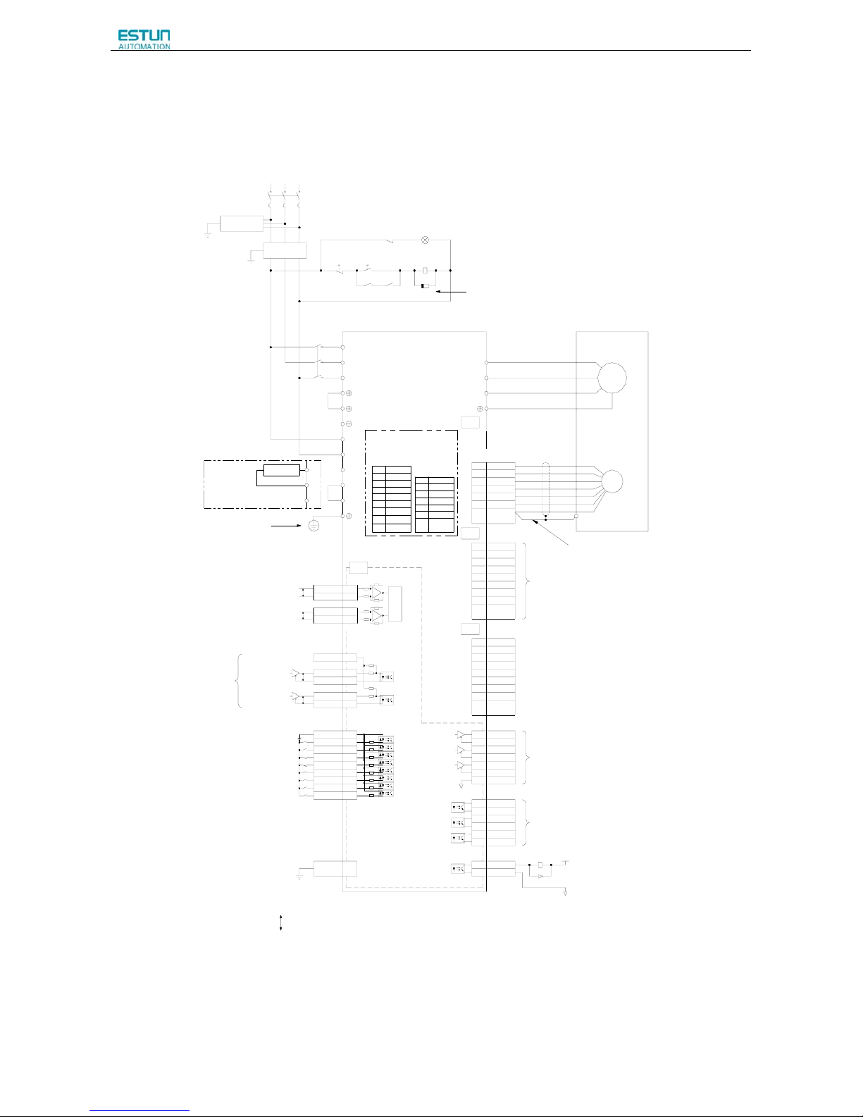
ProNet Series AC Servo User's Manual
- 41 -
3.5.2 Three-phase 200V ProNet-08A~50A/ProNet-E-08A~50A
Nois e Filter
L1 L2 L3
Three-p hase 200~230V (50/60Hz)
+10%
-15%
Power OFF Power ON
1KM 1SUP
1KM
1Ry
L1
L2
L3
1
2
W
V
U
M
PG
Servomotor
Encoder
A(1)
B(2)
C(3)
D(4)
L2C
L
1C
B1
B2
B3
+
A/D
CN1
CN2
2KΩ
150Ω
150Ω
2KΩ
PULS / CW / A
SIGN / CCW / B
Connect Shield to Connector Shell.
ProNet
Series Servodrives
Open-collector Reference Use
Speed Reference(±0~10V/Rated Speed)
Torque Referen ce (±0~10V/ Rated Torqu e)
Position Reference
Signal alloca tons can be modified:
S-ON: Servo ON
P-CON: P Control
P-OT: Forward Run Prohibited
N-OT: Reve rse Run Prohibi ted
ALM-RST: Alarm Reset
CLR: Clear Error Pulse
P-CL: Forward Torque Limit
N-CL: Reverse Torque Limit
SHOM: Home
ORG: Zero Position
+24V
PP P P
PG Divided Ratio Output:
Applicable Line Receiver
AM26LS32A Manufactured by TI or the Equivalent.
P
Represents Twisted-pair Wires
-
-
+
ref
ref
40K
10K
40K
10K
CN3
CN4
Use special communication cable to connect
PC(Personal Computer).
1Ry
1D
+24V
0V
Surge Protector
Magnetic Contac tor
Molded-case Circuit Breaker
1Ry
1PL (Servo Alarm Display )
1
2
485+3
ISO_GND
4
ISO_GND
5
485-6
CANH7
CANL8
N.C.1
N.C.2
485+3
ISO_GND
4
ISO_GND
5
485-6
CANH7
CANL8
PAO+20
PAO-21
PBO+22
PBO-23
PCO+24
PCO-25
DGND50
TGON+5
TGON-6
S-RDY+
9
S-RDY-10
V-CMP+11
V-CMP-12
ALM+7
ALM-8
VREF+ 1
VREF- 2
TREF+ 26
TREF- 27
PPI 34
PULS+ 30
PULS- 31
SIGN+ 32
SIGN- 33
DICOM 13
S-ON 14
P-CON 15
P-OT 16
N-OT 17
ALM-RST 39
CLR 40
P-CL 41
N-CL 42
Shield
Shell
S+7
S-8
BAT+17
BAT-18
PG5V9
PG0V19
Shield
Serial Encoder
B2
B1
External Regenerator Resisotr
B3
Shell
Shield
Shell
Shield
Shell
Be sure to connect a surge suppressor to the
excitation coil of the magnetic contact or and relay.
Be sure to prepare the end of the
shielded wire properly.
Be sure to ground
Signal Allocations can be Modified:
V-CMP: Speed Coincidence
COIN: Positio ning Completion
TGON:Rotation Detection
S-RDY:Servo Ready
CLT:Torque Limit Detection
BK:Brake Interlock
PGC: Encoder C-Pulse Output
OT:Over Travel
RD: Servo Enabled Motor Excitation Output
HOME : Ho me Co mplet ion Out put
ALM: Servo Alarm Output
Photocoupler Output:
Maximum Op erating V oltage :DC30V
Maximum O utput Current: DC50mA
3.3KΩ
N.C.
N.C.
Note: Do not short terminal 1 and 2 of CN3.
SIN+7
SIN-8
COS+17
COS-18
R19
R2
19
ShieldShell
Resolver
Option
A+
1
A-2
B+3
B-4
C+5
C-6
Incremental Wire-saving
Encoder(2500P/R)
Shell
Shield
7,8,9
17,18,19
PG5V
PG0V
Page 44

ProNet Series AC Servo User's Manual
- 42 -
3.5.3 Three-phase 400V ProNet-10D~75D/ProNet-E-10D~50D
Noise Filter
L1 L2 L3
Three-phase 380~480V (50/60Hz)
+10%
-15%
Power OFF Power ON
1KM 1SUP
1KM
1Ry
L1
L2
L3
1
2
W
V
U
M
PG
Servomotor
Encoder
A(1)
B(2)
C(3)
D(4)
B1
B2
B3
+
A/D
CN1
CN2
2KΩ
150Ω
150Ω
2KΩ
PULS / CW / A
SIGN / CCW / B
Connect Shield to Connector Shell.
ProNet
Series Servodrives
Open-collector Reference Use
Speed Reference(±0~10V/Rated Speed)
Torque Reference (±0~10V/Rated Torque)
Position Reference
Signal allocatons can be modif ied:
S-ON: Servo ON
P-CON: P Contr ol
P-OT: Forward Run Prohibited
N-OT: Reverse Run Prohibited
ALM-RST: Alarm Reset
CLR: Clear Er ror Pulse
P-CL: Forward Torque Limit
N-CL: Reverse Torque Limit
SHOM: Home
ORG: Zero Posi tion
+24V
PP P P
PG Divided Ratio Output:
Applicable Line Receiver
AM26LS32A Manufactured by TI or the Equivalent.
P
Represents Twisted-pair Wires
-
-
+
ref
ref
40K
10K
40K
10K
CN3
CN4
Use special communication cable to connect
PC(Personal Computer).
1Ry
1D
+24V
0V
Surge Protector
Magnetic Contactor
Molded-case Circuit Breaker
1Ry
1PL (Servo Alarm Display)
1
2
485+3
ISO_GND
4
ISO_GND
5
485-6
CANH7
CANL
8
N.C.1
N.C.2
485+3
ISO_GND
4
ISO_GND
5
485-6
CANH7
CANL8
PAO+20
PAO-21
PBO+22
PBO-
23
PCO+24
PCO-25
DGND50
TGON+5
TGON-
6
S-RDY+9
S-RDY-10
V-CMP+11
V-CMP-
12
ALM+7
ALM-8
VREF+ 1
VREF- 2
TREF+ 26
TREF- 27
PPI 34
PULS+
30
PULS- 31
SIGN+ 32
SIGN-
33
DICOM 13
S-ON 14
P-CON 15
P-OT
16
N-OT 17
ALM-RST 39
CLR 40
P-CL 41
N-CL 42
Shield
Shell
S+7
S-
8
BAT+17
BAT-18
PG5V9
PG0V19
Shield
Serial Encoder
B2
B1
External Re generator Resis otr
B3
Shell
Shield
Shell
Shield
Shell
Be sure to connect a surge suppressor to the
excitation coil of the magnetic c ontactor and relay.
Be sure to prepare the end of the
shielded wire properly.
Be sure to ground
Signal Allocations can be Modified:
V-CMP: Speed Coincidence
COIN: Positioning Completion
TGON:Rotation Detection
S-RDY:Servo Ready
CLT:Torque Limit Detection
BK:Brake Interlock
PGC: Encoder C-Puls e Output
OT:Over Trav el
RD: Servo Enabled Motor Excitation Output
HOME: Home Completion Output
ALM: Servo Alarm Output
Photocoupler Output:
Maximum Operating Voltage:DC30V
Maximum Output Current:DC50mA
3.3KΩ
N.C.
N.C.
Note: Do not short terminal 1 and 2 of CN3.
SIN+7
SIN-8
COS+17
COS-18
R19
R2
19
ShieldShell
Resolver
Option
A+1
A-2
B+
3
B-4
C+
5
C-6
Incremental Wire-saving
Encoder(2500P/R)
Shell
Shield
7,8,9
17,18,19
PG5V
PG0V
GND
24V
24VDC Power Supply
Page 45
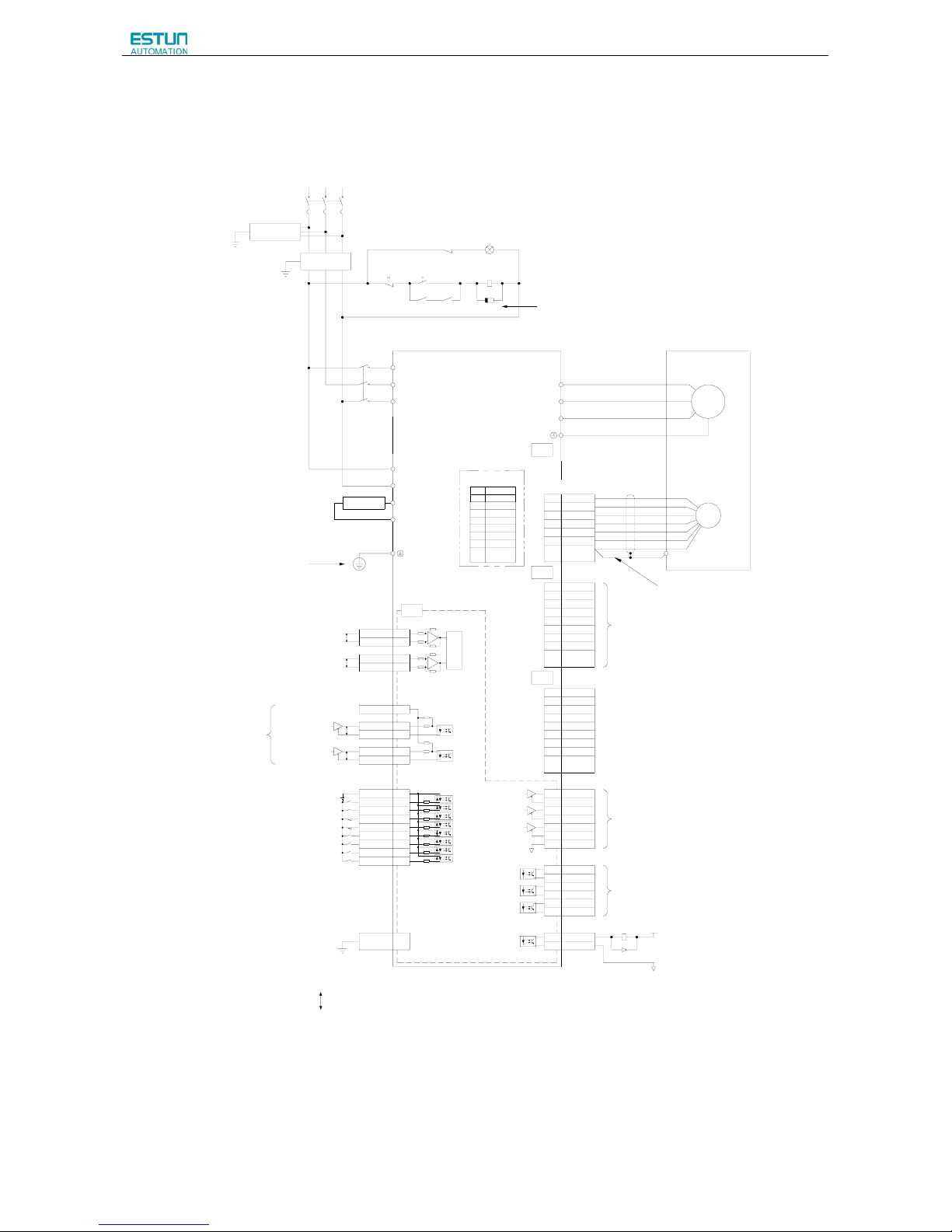
ProNet Series AC Servo User's Manual
- 43 -
3.5.4 Three-phase 400V ProNet-1AD~2BD
Noise Filter
L1 L2 L3
Three-phase 380~440V (50/60Hz)
+10%
-15%
Power OFF Power ON
1KM 1SUP
1KM
1Ry
L1
L2
L3
W
V
U
M
PG
Servomotor
Encoder
A(1)
B(2)
C(3)
D(4)
L2C
L
1C
+
A/D
CN1
CN2
2KΩ
150Ω
150Ω
2KΩ
PULS / CW / A
SIGN / CCW / B
Connect Shield to Connector Shell.
ProNet
Series Servodrives
Open-collector Reference Use
Speed Reference(±0~10V/Rated Speed)
Torque Reference (±0~10V/Rated Torque)
Position Reference
Signal allocatons can be modified:
S-ON: Servo ON
P-CON: P Control
P-OT: Forwar d Run Prohibited
N-OT: Reverse Run Prohibited
ALM-RST: Alarm Reset
CLR: Clear Error Pulse
P-CL: Forwa rd Torque Limit
N-CL: Reverse Torque Limit
SHOM: Home
ORG: Zero Position
+24V
PP P P
PG Divided Ratio Output:
Applicable Line Receiver
AM26LS32A Manufactured by TI or the Equivalent.
P
Represents Twisted-pair Wires
-
-
+
ref
ref
40K
10K
40K
10K
CN3
CN4
Use special communication cable to connect
PC(Personal Computer).
1Ry
1D
+24V
0V
Surge Protector
Magnetic Contactor
Molded-case Circuit Breaker
1Ry
1PL (Servo Alarm Display)
1
2
485+3
ISO_GND
4
ISO_GND
5
485-6
CANH7
CANL8
N.C.1
N.C.
2
485+3
ISO_GND
4
ISO_GND
5
485-6
CANH7
CANL8
PAO+20
PAO-21
PBO+22
PBO-
23
PCO+24
PCO-25
DGND50
TGON+
5
TGON-6
S-RDY+9
S-RDY-10
V-CMP+11
V-CMP-12
ALM+7
ALM-
8
VREF+ 1
VREF- 2
TREF+ 26
TREF- 27
PPI 34
PULS+
30
PULS-
31
SIGN+ 32
SIGN- 33
DICOM 13
S-ON 14
P-CON 15
P-OT
16
N-OT 17
ALM-RST 39
CLR 40
P-CL 41
N-CL 42
Shield
Shell
S+7
S-8
BAT+17
BAT-
18
PG5V9
PG0V19
Shield
Serial Encoder
B2
B1
External Regenerator Resisotr
Shell
Shield
Shell
Shield
Shell
Be sure to connect a surge suppressor to the
excitation coil of the magnetic contactor and relay.
Be sure to prepare the end of the
shielded wire prop erly.
Be sure to ground
Signal Allocations can be Modified:
V-CMP: Speed Coincidence
COIN: Positioning Completion
TGON:Rotation Detection
S-RDY:Servo Ready
CLT:Torque Limit Detec tion
BK:Brake Interlock
PGC: Encoder C-Pulse Output
OT:Over Travel
RD: Servo Enabled Motor Excitation Output
HOME: Home Completio n Output
ALM: Servo Alarm Output
Photocoupler Output:
Maximum Operating Voltage:DC30V
Maximum Output Current:DC50mA
3.3KΩ
Note: Do not shor t terminal 1 and 2 of CN3.
N.C.
N.C.
SIN+7
SIN-
8
COS+17
COS-18
R19
R219
ShieldShell
Resolver
Option
Sensor 1
1
Sensor 2
3
Notes:
1. The resistor of 1500W/20Ω is recommended for the external regenerative resistor of ProNet-1AD.
2. The resistor of 1500W/15Ω is recommended for the external regenerative resistor of ProNet-1ED.
3. The resistor of 1500W/20Ω is recommended for the external regenerative resistor of ProNet-2BD.
Page 46
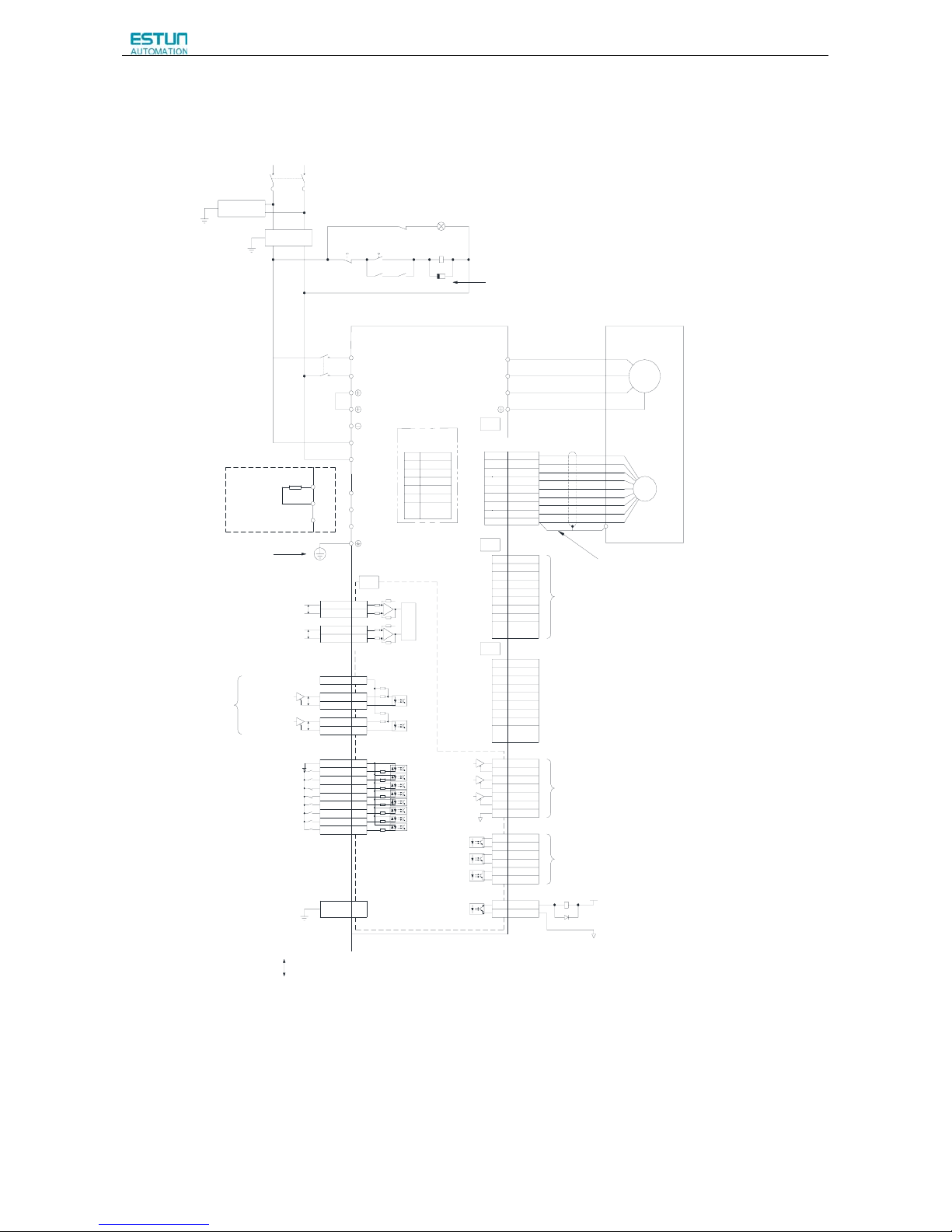
ProNet Series AC Servo User's Manual
- 44 -
3.5.5 Single-phase 100V ProNet-02B/ProNet-E-02B
Noise Filter
L1 L2
single-phase 100~120V (50/60Hz)
+10%
-15%
Power OFF Power ON
1KM 1SUP
1KM
1Ry
L1
L2
1
2
W
V
U
M
Servomotor
A(1)
B(2)
C(3)
D(4)
L2C
L
1C
+
A/D
CN1
CN2
2KΩ
150Ω
150Ω
2KΩ
PULS / CW / A
SIGN / CCW / B
Connect Shield to Connector Shell.
Open-collector Ref erence Use
Speed Reference( ±0~10V/Rated Speed)
Torque Reference (±0~10V / Rated Torque)
Position Reference
Signal allocatons can be modified:
S-ON: Servo ON
P-CON: P Control
P-OT: For ward Run Prohibited
N-OT: Reverse Run Prohibited
ALM-RST: Alarm Reset
CLR: Clear Error Pulse
P-CL: Forward Torque Limit
N-CL: Reverse Torque Limit
SHOM: Home
ORG: Zero Position
+24V
PP P P
PG Divided Ratio Output:
Applicable Li ne Receiver
AM26LS32A Manufacture d by TI or the Equiv alent.
P
Represents Twisted-pair Wires
-
-
+
ref
ref
40K
10K
40K
10K
CN3
CN4
Use special communica tion cable to connect
PC(Personal Compute r).
1Ry
1D
+24V
0V
Surge Protector
Molded-case Circui t Breaker
1Ry
1PL (Servo Alarm Displ ay )
1
2
485+3
ISO_GND
4
ISO_GND
5
485-6
CANH7
CANL8
N.C.1
N.C.2
485+3
ISO_GND
4
ISO_GND
5
485-6
CANH7
CANL8
PAO+20
PAO-21
PBO+22
PBO-23
PCO+24
PCO-
25
DGND50
TGON+5
TGON-6
S-RDY+9
S-RDY-
10
V-CMP+11
V-CMP-12
ALM+7
ALM-8
VREF+ 1
VREF-
2
TREF+ 26
TREF- 27
PPI 34
PULS+ 30
PULS- 31
SIGN+ 32
SIGN- 33
DICOM 13
S-ON 14
P-CON 15
P-OT 16
N-OT 17
ALM-RST
39
CLR 40
P-CL 41
N-CL 42
Shield
Shell
Shield
Shell
Shield
Shell
Be sure to co nnect a surge su ppressor to the
excitation co il of the magnet ic contactor and relay.
Be sure to ground
Signal Alloca tions can be Modif ied:
V-CMP: Speed Coincide nce
COIN: Positioning Completion
TGON:Rotation Detection
S-RDY:Servo Ready
CLT:Torque Limit Dete ction
BK:Brake Interlock
PGC: Encoder C-Pulse Out put
OT:Over Travel
RD: Servo Enabled Motor Excitation Output
HOME: Home Co mpletion Ou tput
ALM: Servo Alarm Output
Photocoupler Output:
Maximum Operatin g Voltage:DC30V
Maximum Output Current:DC50mA
3.3KΩ
N.C.
N.C.
Note: Do not short terminal 1 and 2 of CN3.
B1
B2
B3
B1
B2
B3
External Regenerator Resistor
Encoder
Be sure to prepare the end of the
shielded wire properly.
PG
A+1
A-2
B+3
B-
4
PG5V
5
PG0V
6
7,8,9
17,18,19
Shell
C+
C-
Shield
Incremental W ire-saving
Encoder(2500P/ R)
S+7
S-8
BAT+17
BAT-18
PG5V9
PG0V19
Shield
Serial Encoder
Shell
Option
Page 47
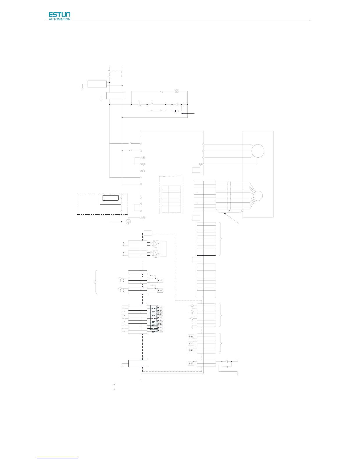
ProNet Series AC Servo User's Manual
- 45 -
3.5.6 Single-phase 100V ProNet-04B /ProNet-E-04B
Noise Filter
L1 L2
single-phas e 100~120V (50/60Hz)
+10%
-15%
Power OFF Power ON
1KM 1SUP
1KM
1Ry
L1
L2
1
2
W
V
U
M
Servomot or
A(1)
B(2)
C(3)
D(4)
L2C
L
1C
+
A/D
CN1
CN2
2KΩ
150Ω
150Ω
2KΩ
PULS / CW / A
SIGN / CCW / B
Connect Shield to Connector Shell.
Open-collec tor Reference Use
Speed Ref erence(±0 ~10V/Rated Speed)
Torque R eference ( ±0~10V / Rated Torque)
Position Reference
Signal alloc atons can be modified:
S-ON: Servo ON
P-CON: P Control
P-OT: Forward R un Prohibited
N-OT: Revers e Run Prohibited
ALM-RST: Alarm Reset
CLR: Clear Error Pulse
P-CL: Fo rward Torque Limit
N-CL: R everse Torque Limit
SHOM: Home
ORG: Zero Position
+24V
PP P P
PG Divided Rati o Output:
Appli cable Line Recei ver
AM26LS32A Manufactured by TI or the Equivalent.
P
Represents Twi sted-pair Wires
-
-
+
ref
ref
40K
10K
40K
10K
CN3
CN4
Use spe cial commu nication c able to connect
PC(Personal Computer).
1Ry
1D
+24V
0V
Surge Protector
Molded- case Circui t Breaker
1Ry
1PL (Servo Alarm Display)
1
2
485+3
ISO_GND
4
ISO_GND
5
485-6
CANH7
CANL8
N.C.1
N.C.2
485+3
ISO_GND
4
ISO_GND
5
485-6
CANH7
CANL
8
PAO+
20
PAO-21
PBO+22
PBO-
23
PCO+24
PCO-
25
DGND
50
TGON+
5
TGON-
6
S-RDY+
9
S-RDY-
10
V-CMP+11
V-CMP-12
ALM+7
ALM-
8
VREF+ 1
VREF- 2
TREF+
26
TREF- 27
PPI
34
PULS+
30
PULS-
31
SIGN+
32
SIGN-
33
DICOM
13
S-ON 14
P-CON
15
P-OT
16
N-OT 17
ALM-RST
39
CLR
40
P-CL 41
N-CL 42
Shield
Shell
Shield
Shell
Shield
Shell
Be sure to connect a surge suppressor to the
excit ation coi l of the magnet ic contactor and relay.
Be sure to ground
Signal Allocations can be Modified:
V-CMP: S peed Coincidence
COIN: Positioning Completion
TGON:Rotation Detection
S-RDY:Servo Ready
CLT:Torque Limit Detection
BK:Brake Interlock
PGC: Encoder C-Pulse Output
OT:Over Travel
RD: Servo Enabled Mot or Excitation Output
HOME: Home Completion Output
ALM: Servo Alarm Output
Photocoupler Output:
Maximum Op erating Vol tage:DC30V
Maximum Ou tput Current :DC50mA
3.3KΩ
N.C.
N.C.
Note: Do not short terminal 1 and 2 of CN3.
B1
B2
B3
Encoder
Be sure to prepare the end of the
shielded wi re properly.
PG
A+
1
A-2
B+3
B-4
PG5V
5
PG0V
6
7,8,9
17,18,19
Shell
C+
C-
Shield
Incremental Wi re-saving
Encoder(2500P/R)
B2
B1
External Regenerator Resisotr
B3
S+7
S-
8
BAT+17
BAT-
18
PG5V
9
PG0V
19
Shield
Serial Encoder
Shell
Option
Page 48

ProNet Series AC Servo User's Manual
- 46 -
3.5.7 Single-phase 100V ProNet-08B/ ProNet-E-08B
Noise Filter
L1 L2
single-phas e 100~120V (50/60Hz)
+10%
-15%
Power OFF Power ON
1KM 1SUP
1KM
1Ry
L1
L2
1
2
W
V
U
M
Servomot or
A(1)
B(2)
C(3)
D(4)
L2C
L
1C
+
A/D
CN1
CN2
2KΩ
150Ω
150Ω
2KΩ
PULS / CW / A
SIGN / CCW / B
Connect Shield to Connector Shell.
Open-collec tor Reference Use
Speed Ref erence(±0~ 10V/Rated Speed)
Torque R eference ( ±0~10V / Rated Torque)
Position Reference
Signal alloc atons can be modified:
S-ON: Servo ON
P-CON: P Control
P-OT: Fo rward Run Prohi bited
N-OT: Revers e Run Prohibited
ALM-RST: Alarm Reset
CLR: Clear Error Pulse
P-CL: Fo rward Torque Limit
N-CL: R everse Torque Limit
SHOM: Home
ORG: Zero Position
+24V
PP P P
PG Divided Rati o Output:
Appli cable Line Recei ver
AM26LS32A Manufactur ed by TI or the Equivalent.
P
Represents Twi sted-pair Wires
-
-
+
ref
ref
40K
10K
40K
10K
CN3
CN4
Use spe cial commu nication cabl e to connect
PC(Personal Computer).
1Ry
1D
+24V
0V
Surge Protector
Molded- case Circui t Breaker
1Ry
1PL (Servo Alarm Display)
1
2
485+3
ISO_GND
4
ISO_GND
5
485-6
CANH7
CANL8
N.C.1
N.C.2
485+3
ISO_GND
4
ISO_GND
5
485-6
CANH7
CANL
8
PAO+
20
PAO-21
PBO+22
PBO-
23
PCO+24
PCO-
25
DGND
50
TGON+
5
TGON-
6
S-RDY+
9
S-RDY-
10
V-CMP+11
V-CMP-12
ALM+7
ALM-
8
VREF+ 1
VREF- 2
TREF+
26
TREF- 2 7
PPI
34
PULS+
30
PULS-
31
SIGN+
32
SIGN-
33
DICOM
13
S-ON 14
P-CON
15
P-OT
16
N-OT 17
ALM-RST
39
CLR
40
P-CL 41
N-CL 42
Shield
Shell
Shield
Shell
Shield
Shell
Be sure to connect a surge suppressor to the
excitation coil of the magnetic contactor and relay.
Be sure to ground
Signal Allocations can be Modified:
V-CMP: S peed Coincidence
COIN: Positioning Completion
TGON:Rotati on Detection
S-RDY:Servo Ready
CLT:Torque Limit Detection
BK:Brake Interlock
PGC: Encoder C-Pulse Output
OT:Over Travel
RD: Servo Enabled Mot or Excitation Output
HOME: Home Completion Output
ALM: Servo Alarm Output
Photocoupler Output:
Maximum Op erating Vol tage:DC30V
Maximum Ou tput Current :DC50mA
3.3KΩ
N.C.
N.C.
Note: Do not short terminal 1 and 2 of CN3.
B1
B2
B3
Encoder
Be sure to prepar e the end of the
shielded wi re properly.
PG
A+
1
A-2
B+3
B-4
PG5V
5
PG0V
6
7,8,9
17,18,19
Shell
C+
C-
Shield
Incremental Wi re-saving
Encoder(2500P/R)
B2
B1
External Regenerator Resisotr
B3
S+7
S-
8
BAT+17
BAT-
18
PG5V
9
PG0V
19
Shield
Serial Encoder
Shell
Option
Notes:
When single-phase 100VAC is provided for main circuit on rated speed, instantaneous peak torque≤4.78 N.m.
When three-phase 100VAC is provided for main circuit on rated speed, instantaneous peak torque≤7.16 N.m.
Page 49
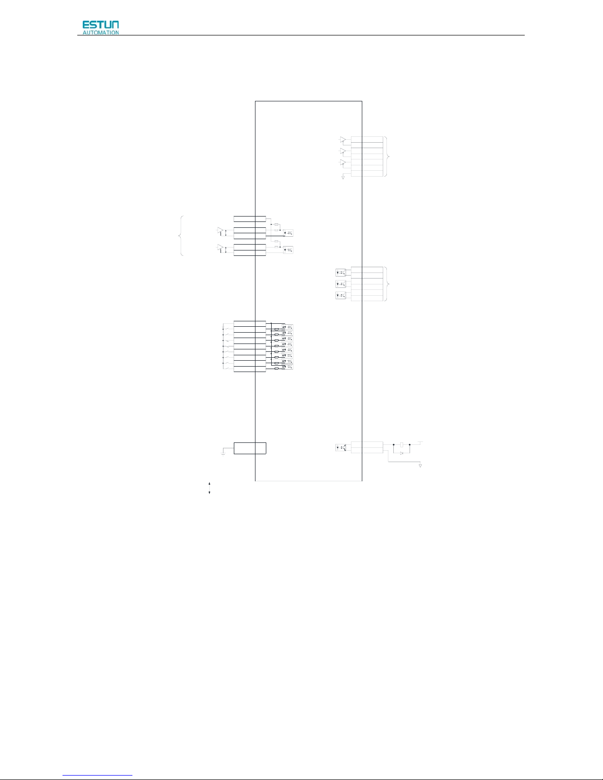
ProNet Series AC Servo User's Manual
- 47 -
3.5.8 Position Control Mode
2KΩ
150Ω
150Ω
2KΩ
PULS / CW / A
SIGN / CCW / B
+24V
PP
P
1Ry
1D
+24V
0V
PAO+20
PAO-21
PBO+22
PBO-23
PCO+24
PCO-25
DGND50
TGON+5
TGON-6
S-RDY+
9
S-RDY-
10
COIN+11
COIN-12
ALM+7
ALM-8
PPI 34
PULS+ 30
PULS-
31
SIGN+
32
SIGN- 33
DICOM 13
S-ON 14
P-CON 15
P-OT 16
N-OT
17
ALM-RST
39
CLR
40
P-CL 41
N-CL 42
Shield
ProNet
Series Servodrives
Open-collector Reference Use
Position Reference
Signal al locatons can be modified:
S-ON: Servo ON
P-CON: P Control
P-OT: Forward Run Prohibited
N-OT: Reverse Run Prohibited
ALM-RST: Ala rm Reset
CLR: Clear Error Pulse
P-CL: Forward Tor que Limit
N-CL: Revers e Torque Limit
SHOM: Home
ORG: Zero Position
Shell
Connect Shield to Connector Shell.
Represents Twisted-pair Wires
ALM: Servo Alarm Output
Photocoupler Output:
Maximum Operating Voltage:DC30V
Maximum Output Current:DC50mA
Signal Allocati ons can be Modified:
V-CMP: Speed Coincidence
COIN: Positioning Completion
TGON:Rotation Detection
S-RDY:Servo Ready
CLT:Torque Limit Detection
BK:Brake Interlock
PGC: Encoder C-Pulse Output
OT:Over Travel
RD: Servo Enabled Motor Excitation Output
HOME: Home Completion Output
PG Divided Ratio Output:
Applicable Line Receiver
AM26LS32A Manufactured by TI or the Equivalent.
3.3KΩ
Page 50
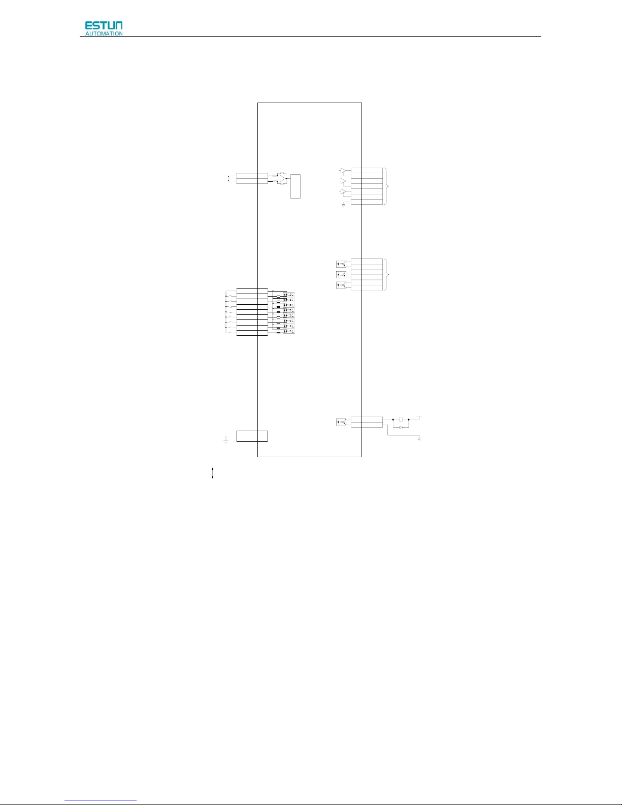
ProNet Series AC Servo User's Manual
- 48 -
3.5.9 Speed Control Mode
+
A/D
+24V
P
P
-
ref
40K
10K
40K
10K
1Ry
1D
+24V
0V
PAO+20
PAO-21
PBO+22
PBO-23
PCO+24
PCO-25
DGND50
TGON+
5
TGON-6
S-RDY+9
S-RDY-
10
V-CMP+11
V-CMP-12
ALM+7
ALM-
8
VREF+ 1
VREF-
2
DICOM
13
S-ON 14
P-CON
15
P-OT
16
N-OT 17
ALM-RST
39
CLR 40
P-CL 41
N-CL 42
Shield
ALM: Servo Alarm Output
Photocoupler Output:
Maximum Operating Voltage:DC30V
Maximum Output Current:DC50mA
Represents Twisted-pair Wires
Shell
Connect Shield to Connector Shell.
Signal allocatons can be m odified:
S-ON: Servo ON
P-CON: P Control
P-OT: Forward Run Prohibited
N-OT: Reverse Run Prohibited
ALM-RST: Alarm Reset
CLR: Clear Error Pulse
P-CL: Forward Torque Limit
N-CL: Reverse Torque Limit
SHOM: Home
ORG: Zero Position
Signal Allocations can be Modified:
V-CMP: Speed Coincidence
COIN: Positioning Completion
TGON:Rotation Detection
S-RDY:Servo Ready
CLT:Torque Limit Detection
BK:Brake Interlock
PGC: Encoder C-Pulse Output
OT:Over Travel
RD: Servo Enabled Motor Excitation Output
HOME: Home Completion Output
PG Divided Ratio Output:
Applicable Line Receiver
AM26LS32A Manufactured by TI or the Equiva lent.
ProNet
Series Servodrives
Speed Reference(±0~10V/Rated Speed)
3.3KΩ
Page 51

ProNet Series AC Servo User's Manual
- 49 -
3.5.10 Torque Control Mode
A/D
+24V
P
P
-
+
ref
1Ry
1D
+24V
0V
PAO+
20
PAO-21
PBO+22
PBO-23
PCO+24
PCO-25
DGND50
TGON+5
TGON-6
S-RDY+9
S-RDY-10
V-CMP+11
V-CMP-
12
ALM+7
ALM-8
TREF+ 26
TREF- 27
DICOM 13
S-ON 14
P-CON 15
P-OT
16
N-OT 17
ALM-RST 39
CLR
40
P-CL 41
N-CL 42
Shield
ProNet
Series Servodrives
Torque Reference (±0~10V/Rat ed Torque)
Signal allocatons can be modified:
S-ON: Servo ON
P-CON: P Control
P-OT: Forward Ru n Prohibited
N-OT: Reverse Run Prohibited
ALM-RST: Alarm Reset
CLR: Clear Error Pulse
P-CL: Forward Torque Limit
N-CL: Reverse Torque Limit
SHOM: Home
ORG: Zero Position
Connect Shield to Connector Shell.
Represents Twisted- pair Wires
Shell
ALM: Servo Alarm Output
Photocoupler Output:
Maximum Operating Voltage:DC30V
Maximum Output Current:DC50mA
Signal Allocations can be Modified:
V-CMP: Speed Coincidence
COIN: Positioning Completion
TGON:Rotation Detection
S-RDY:Servo Ready
CLT:Torque Limit Detection
BK:Brake Interlock
PGC: Encoder C-Pulse Output
OT:Over Travel
RD: Servo Enabled Motor Excitation Output
HOME: Home Completion Output
PG Divided Ratio Output:
Applicable Line Receiver
AM26LS32A Manufactured by TI or the Equivalent.
3.3KΩ
Page 52
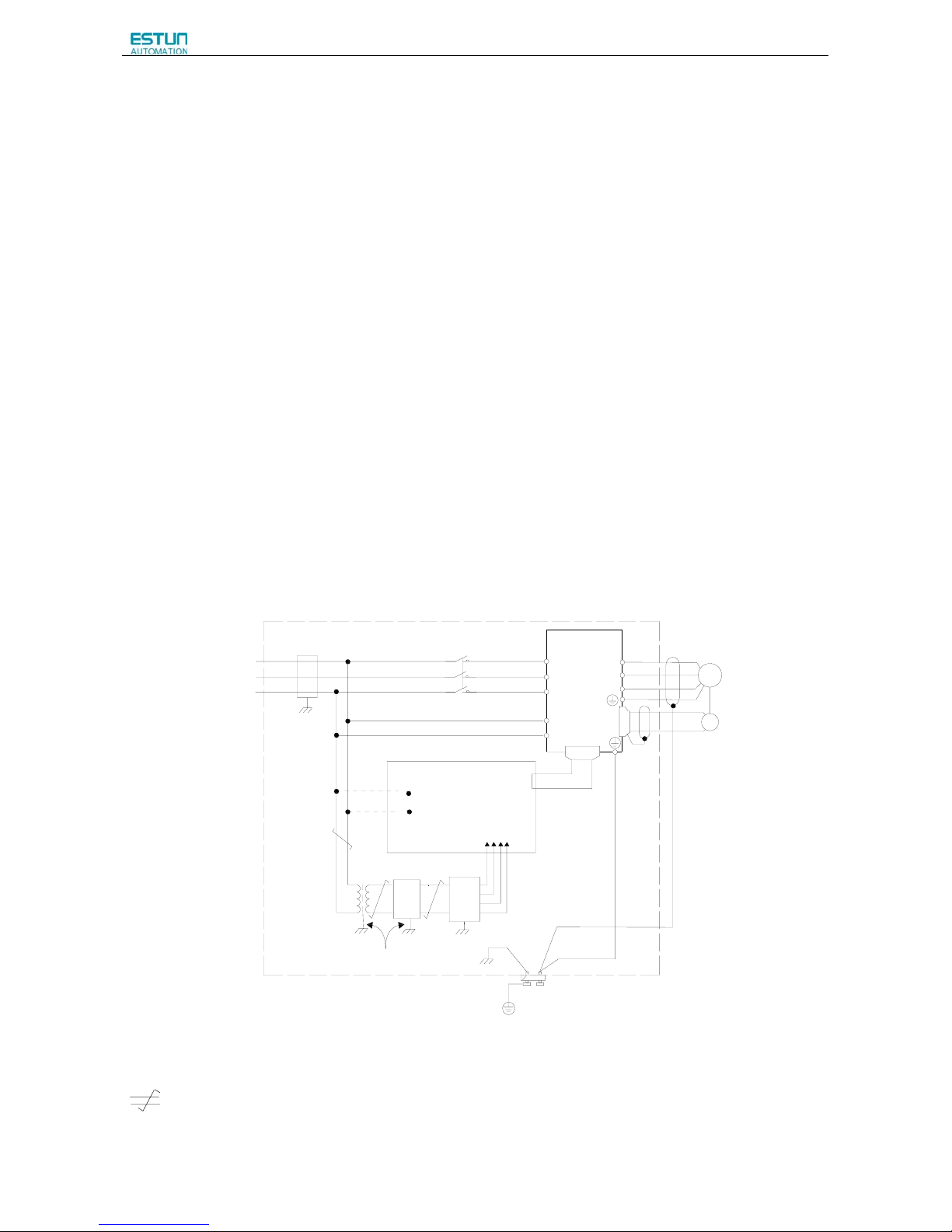
ProNet Series AC Servo User's Manual
- 50 -
3.6 Wiring for Noise Control
3.6.1 Noise Control
The servo drive uses high-speed switching elements in the main circuit. It may receive "switching noise" from these
high-speed switching elements.
To prevent malfunction due to noise, take the following actions:
• Position the input reference device and noise filter as close to the servo drive as possible.
• Always install a surge absorber in the relay, solenoid and electromagnetic contactor coils.
• The distance between a power line (servomotor main circuit cable) and a signal line must be at least 30 cm. Do not put
the power and signal lines in the same duct or bundle them together.
• Do not share the power supply with an electric welder or electrical discharge machine. When the servo drive is placed
near a high-frequency generator, install a noise filter on the input side of the power supply line. As for the wiring of noise
filter, refer to (1) Noise Filter shown below.
• For proper grounding technique, refer to (2) Correct Grounding.
(1) Noise Filter
Please install a noise filter in the appropriate place to protect the servo drive from external noise interference.
Notice:
AC 200V
AC 400V
Servo Drive
PG
use ground resistor 100Ω max.
Noise filter
*3
2
*1
Operation relay sequence
Signal generation circuit
*3
*2
Noise
filter
DC
power
*1
(ground plate)
Wires of
*1
Ground: Ground to an independent ground
L1
L2
L3
/&
/&
CN1
CN2
M
(FG)
Servomotor
(ground plate)
(ground
plate)
(ground plate)
(ground plate)
3.5mm
min.
2
3.5mm min.
2
3.5mm min.
2
3.5mm min.
2
2mm min.
•For ground wires connected to the ground plate, use a thick wire with a thickness of at least 3.5 mm2 (preferably, plain
stitch cooper wire)
•
should be twisted-pair wires.
•When using a noise filter, follow the precautions in 3.6.2 Precautions on Connecting Noise Filter.
Page 53

ProNet Series AC Servo User's Manual
- 51 -
(2) Correct Grounding
Take the following grounding measures to prevent the servo drive from malfunctioning due to noise.
■ Grounding the Motor Frame
If the servomotor is grounded via the machine, a switching noise current will flow from the servo drive main circuit through
the servomotor stray capacitance.
Always connect servomotor frame terminal FG to the servo drive ground terminal. Also be sure to ground the ground
terminal
.
■ Noise on the I/O Signal Line
If the I/O signal line receives noise, ground the 0 V line (SG) of the reference input line. If the main circuit wiring for the
motor is accommodated in a metal conduit, ground the conduit and its junction box. For all grounding, ground at one point
only.
(3)Precautions on installing on the control panel
■When the servo drive is installed on the control panel, a piece of metal plate should be fixed. It is used for fixing the servo
drive and other peripheral devices. The noise filter should be installed on the metal plate, and closed to the hole drill
through power lines on control panel. Use screws to fix the noise filter to the metal plate. The grounding terminals of noise
filter connects to the grounding terminals of control panel.
■ Servo drive should be fixed on a piece of metal plate. Make sure the heat sink towards ground. The grounding terminals
of servo drive connect to the grounding terminals of control panel.
3.6.2 Precautions on Connecting Noise Filter
(1) Noise Filter Brake Power Supply
Use the noise filter Manufactured by SCHAFFNER at the brake power input for servomotors with holding brakes.
Relationship between servo drive power and noise filter current:
Servo Drive Power Noise Filter Current
0.2kW 1A
0.4kW 2A
0.75kW 4A
1 kW 4A
1.5 kW 6A
2 kW 8A
3 kW 12A
5 kW 20A
7.5kW 30A
11kW 44A
15kW 60A
22kW 88A
Page 54
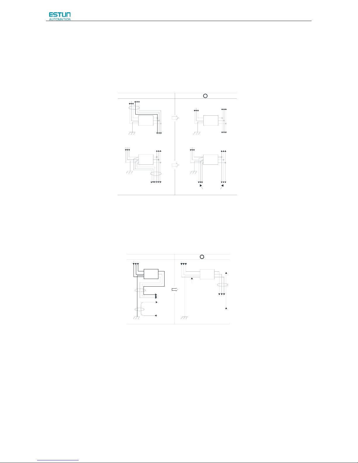
ProNet Series AC Servo User's Manual
- 52 -
Note:
1. A single-phase servomotor should apply a two-phase filter. A three-phase servo drive should apply a
three-phase filter.
2. Choose the right filter according the specifications of operating voltage, current, and manufacturer.
(2) Precautions on Using Noise Filters
Do not put the input and output lines in the same duct or bundle them together.
x
Noise
Filter
Ground plate
Separate these circuits
Noise
Filter
Noise
Filter
Noise
Filter
Ground plate
Ground plate
Ground plate
Separate the noise filter ground wire from the output lines.
Do not accommodate the noise filter ground wire, output lines and other signal lines in the same duct or bundle them
together.
X
Noise
Filter
Ground plate
Noise
Filter
Ground plate
Connect the noise filter ground wire directly to the ground plate. Do not connect the noise filter ground wire to other
ground wires.
Page 55
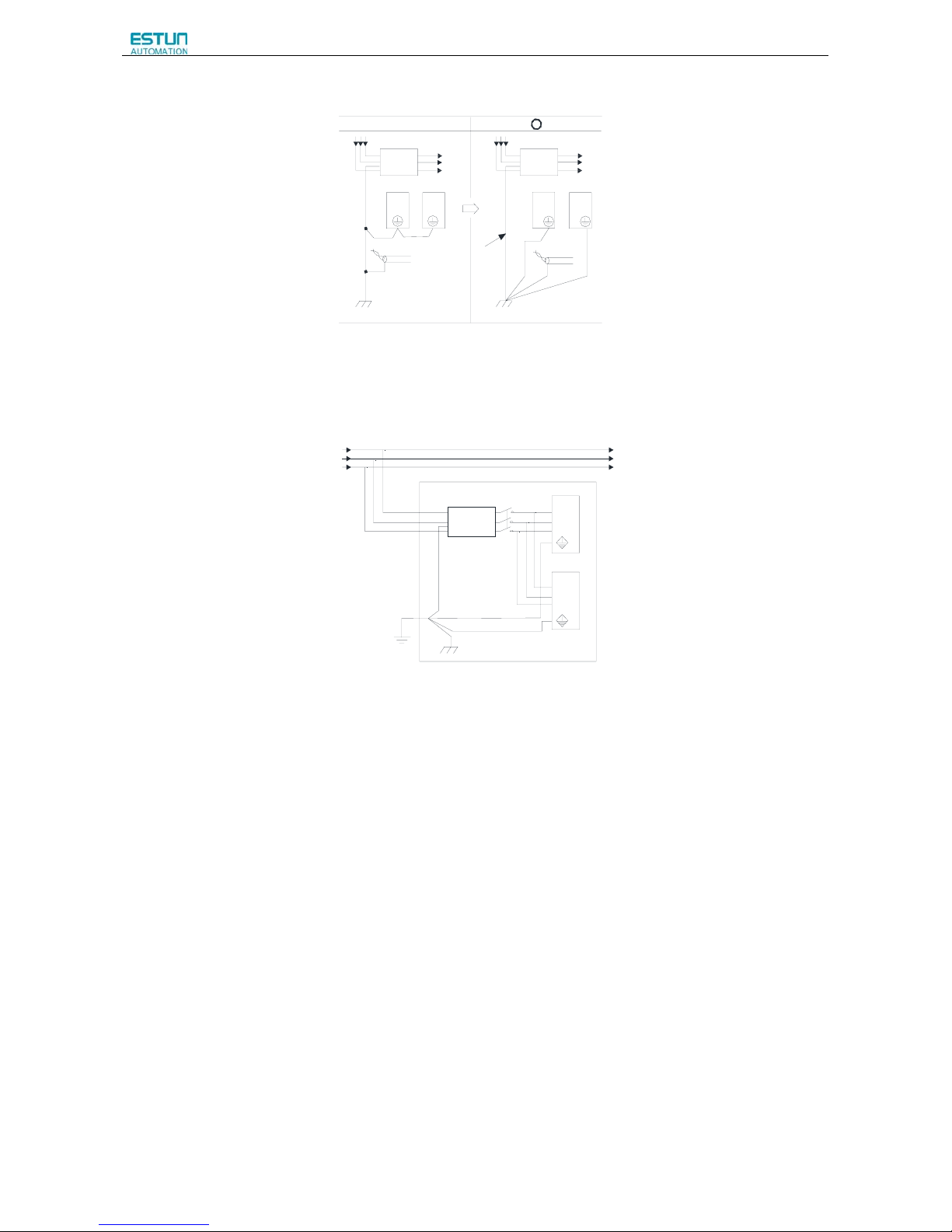
ProNet Series AC Servo User's Manual
- 53 -
Noise
Filter
ground plate
Shielded
ground wire
servodrive
stub
x
Noise
Filter
servodrive
servodrive servodrive
ground plate
If a noise filter is located inside a control panel, connect the noise filter ground wire and the ground wires from other
devices inside the control panel to the ground plate for the control panel first, then ground these wires.
Control Panel
Servodrive
Servodrive
Ground plate
Ground
Noise
Filter
3.7 Installation Conditions of EMC Directives
To adapt a combination of a servomotor and a servodrive to EMC Directives (EN61326-1:2006), the following conditions
must be satisfied.
(1) EMC Installation Conditions
This section describes the installation conditions that satisfy EMC guidelines for each servo drive model.
This section describes the EMC installation conditions satisfied in test conditions prepared by ESTUN. The actual EMC
level may differ depending on the actual system’s configuration, wiring, and other conditions.
Page 56
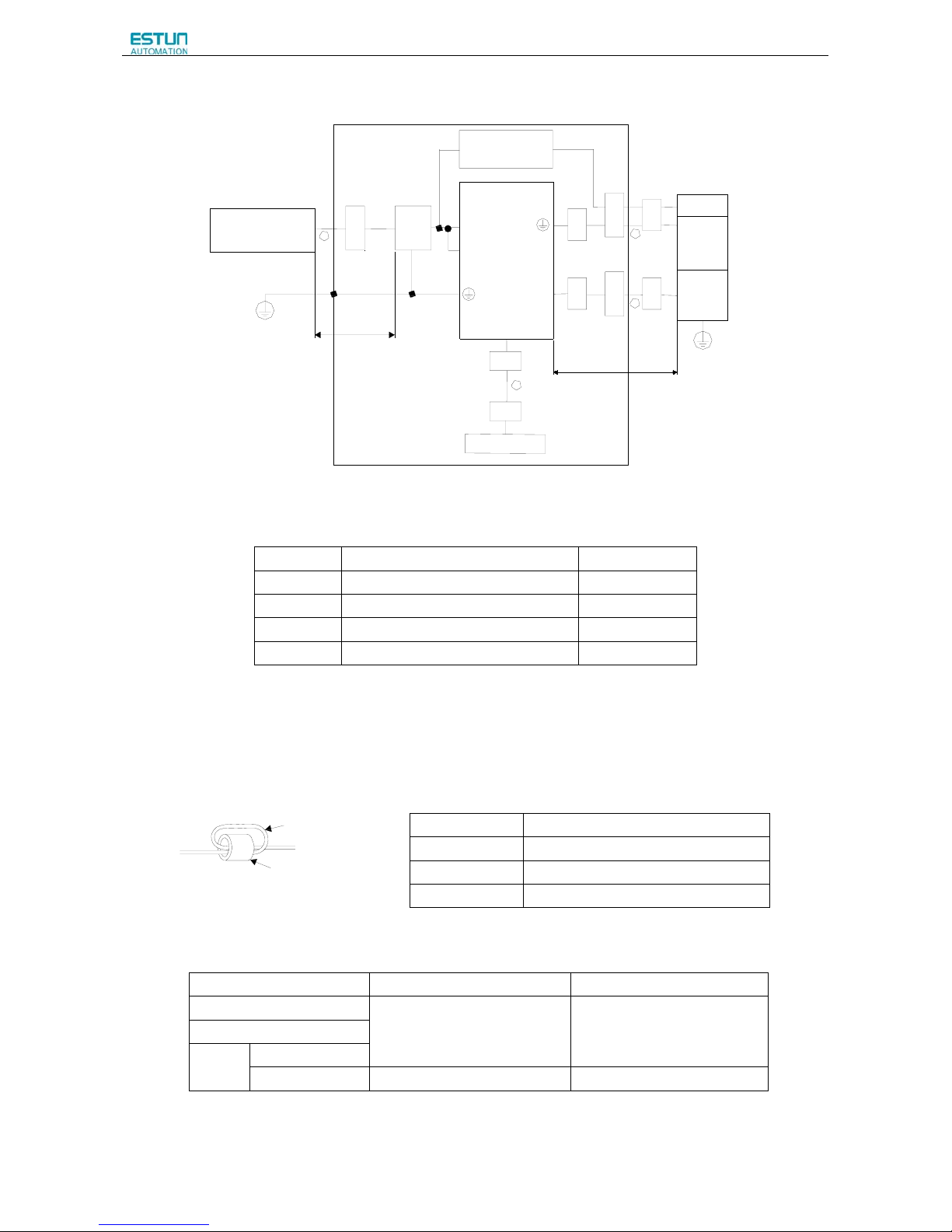
ProNet Series AC Servo User's Manual
- 54 -
Aprox.2m
Noise
filter
1
4
2
3
C
l
a
m
p
C
o
r
e
C
o
r
e
C
o
r
e
C
o
r
e
C
o
r
e
C
o
r
e
C
o
r
e
Aprox.5m
H
o
s
t
c
o
n
t
r
o
l
l
e
r
C
l
a
m
p
C
l
a
m
p
B
r
a
k
e
S
e
r
v
o
-
m
o
t
o
r
E
n
c
o
d
e
r
S
e
r
v
o
D
r
i
v
e
P
E
P
E
U
,
V
,
W
B
r
a
k
e
p
o
w
e
r
s
u
p
p
l
y
L
1
C
,
L
2
C
L
1
,
L
2
,
L
3
C
N
2
C
N
1
P
o
w
e
r
S
u
p
p
l
y
T
h
r
e
e
-
p
h
a
s
e
2
0
0
V
A
C
T
h
r
e
e
-
p
h
a
s
e
4
0
0
V
A
C
G
r
o
u
n
d
/
S
h
i
e
l
d
B
o
x
Notes: The example above shows three-phase 200VAC servo drive connection.
(2) Cable Core and Cable Clamp
(a) Attaching the Ferrite Core
The diagram shows two turns in the cable.
The table shows the cable and the position where the ferrite core is attached.
Cable
Ferrite core
(b) Recommended Ferrite-core
Cable Name Ferrite Core Model Manufacturer
I/O signals cable
ESD-SR-25 TOKIN
Encoder cable
Motor
cable
400W or less
750W or less
PC40T96 × 20 × 70
TDK
Symbol Cable Name Specifications
①
I/O signal cable Shield cable
②
Servomotor cable Shield cable
③
Encoder cable Shield cable
④
AC line cable Shield cable
Cable Name Mounting Position of the Core
I/O signals cable Near the host controller and servodrive.
Motor cable Near the servodrive and servomotor.
Encoder cable Near the servodrive and servomotor.
Page 57
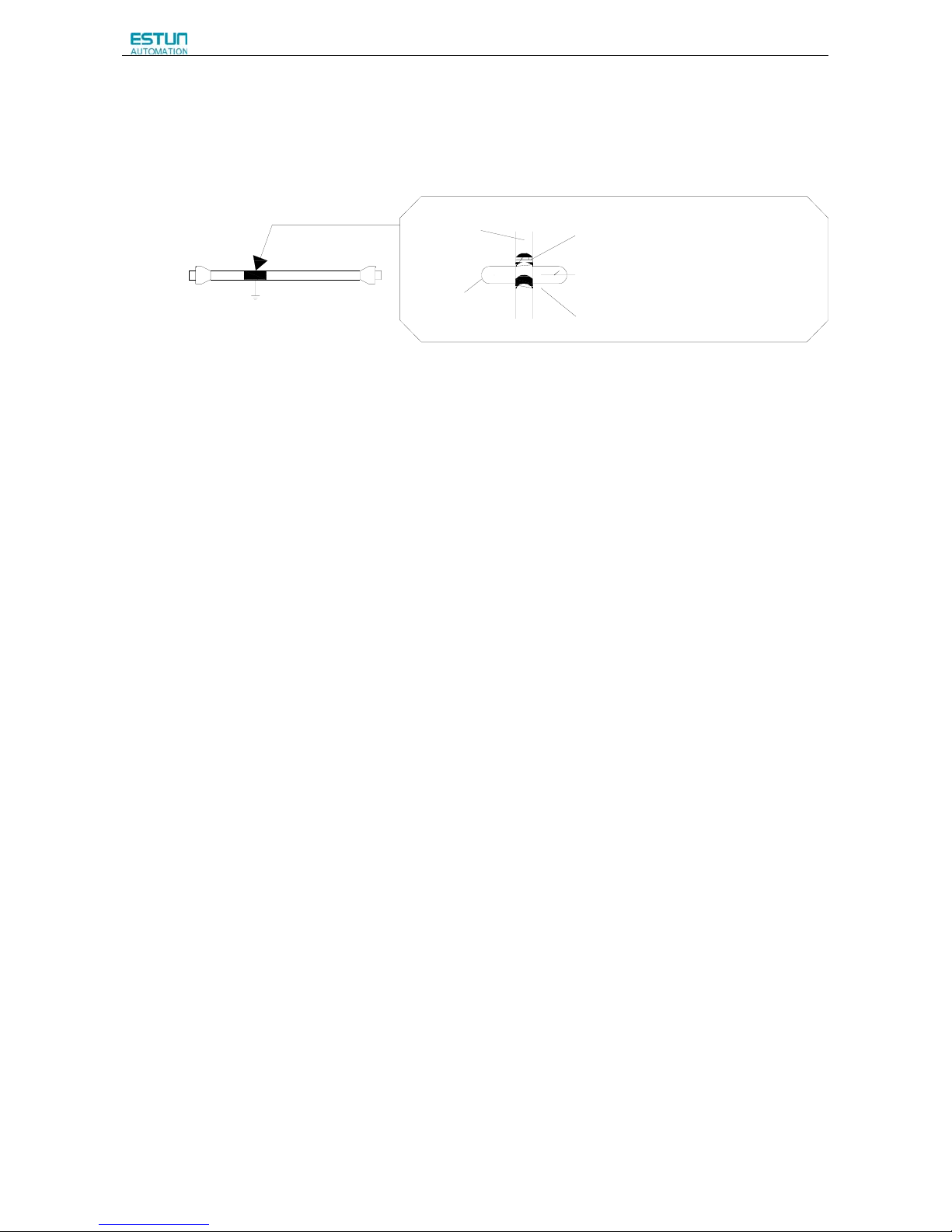
ProNet Series AC Servo User's Manual
- 55 -
(c) Fixing the Cable
Fix and ground the cable shield using a piece of conductive metal.
• Example of Cable Clamp
Host controller side
Ground plate
Cable
Cable clamp
Shield(cable sheath stripped)
Fix and ground the cable shield
using a piece of conductive metal.
Remove paint on mounting surface
(d) Shield Box
A shield box, which is a closed metallic enclosure, should be used for shielding magnetic interference. The structure of the
box should allow the main body, door, and cooling unit to be attached to the ground. The box opening should be as small
as possible.
3.8 Using More than One Servo Drive
The following diagram is an example of the wiring when more than one Servodrive is used.
Connect the alarm output (ALM) terminals for the three Servodrives in series to enable alarm detection relay 1RY to
operate.
When the alarm occurs, the ALM output signal transistor is turned OFF.
Multiple servos can share a single molded-case circuit breaker (QF) or noise filter. Always select a QF or noise filter that
has enough capacity for the total power capacity (load conditions) of those servos.
Page 58

ProNet Series AC Servo User's Manual
- 56 -
+24
0V
M
M
M
Power supply
QF
Noise
filter
1KM
Power
OFF
Power
ON
1KM
1KM
1RY
SA
R
S
T
1RY
S
e
r
v
o
D
r
i
v
e
L
1
L
2
L
3
L
1
C
L
2
C
C
N
1
L
1
L
2
L
3
L
1
C
L
2
C
C
N
1
L
1
L
2
L
3
L
1
C
L
2
C
C
N
1
A
L
M
-
A
L
M
+
A
L
M
-
A
L
M
+
A
L
M
-
A
L
M
+
S
e
r
v
o
D
r
i
v
e
S
e
r
v
o
D
r
i
v
e
S
e
r
v
o
M
o
t
o
r
S
e
r
v
o
M
o
t
o
r
S
e
r
v
o
M
o
t
o
r
Notes:
1. Power supply phase-S should connect to ground terminals.
2. The example above shows three-phase 200VAC servo drive connection.
Page 59
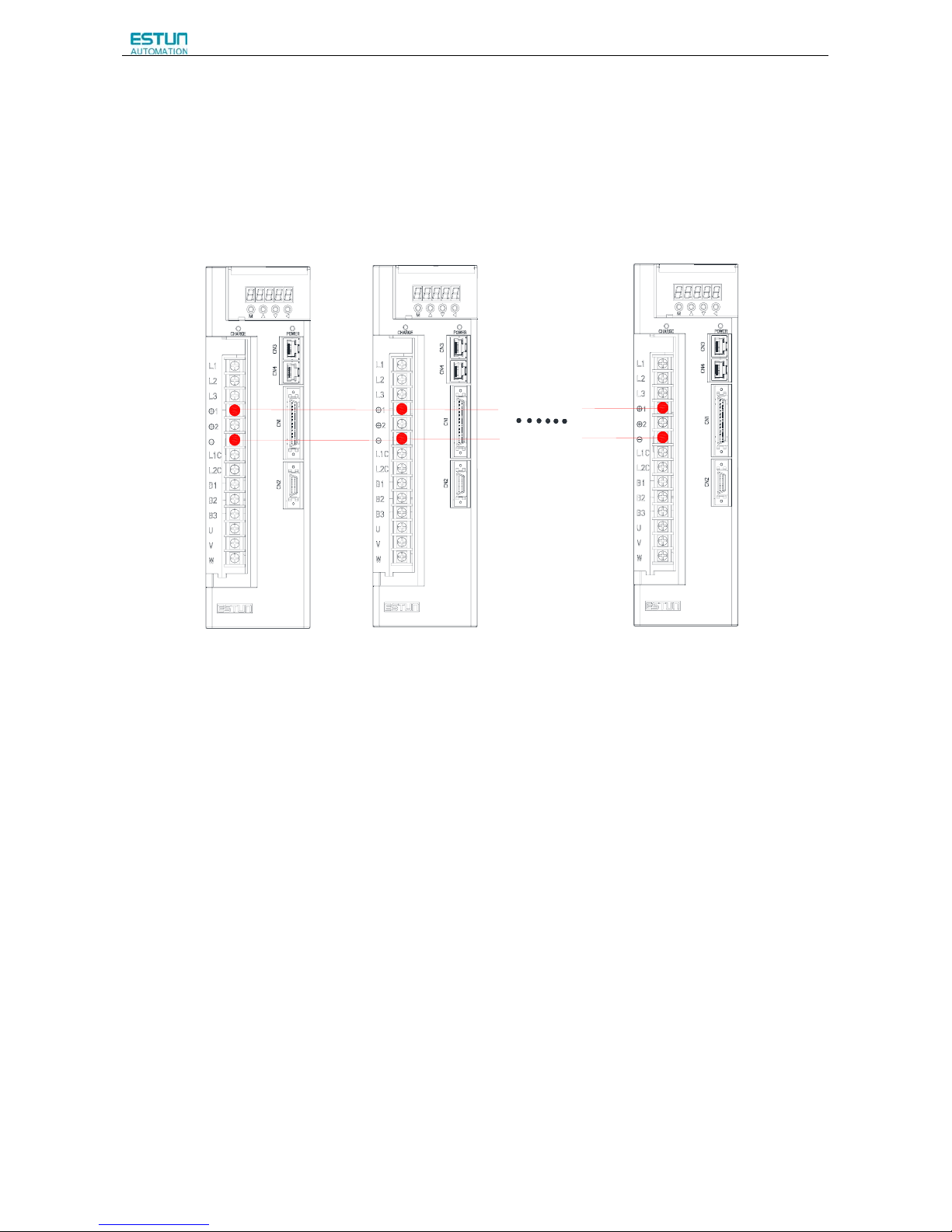
ProNet Series AC Servo User's Manual
- 57 -
3.9 Connecting DC Bus
Servo drive wiring includes standard wiring (standard wiring refers to 3.5 Standard Wiring Examples) and optional
wiring. Connecting DC bus together of the optional wiring conduces to bus voltage more stable. The following diagram is
an example of the wiring when connecting more than one servo drive DC bus.
Notes:
Connecting DC bus together is available only for 200V ProNet and ProNet-E series servo drives. Please use the
wiring on ProNet-08A/10A, ProNet-E-08A/10A directly, and inquire customer service before wiring on other
products.
Page 60
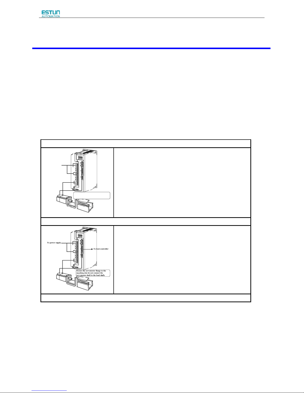
ProNet Series AC Servo User's Manual
- 58 -
Chapter 4
Operation
4.1 Trial Operation
Make sure that all wiring has been completed prior to trial operation.
Perform the following three types of trial operation in order. Instructions are given for speed control mode (standard setting)
and position control mode. Unless otherwise specified, the standard parameters for speed control mode (factory settings)
are used.
(1)Trial Operation for Servomotor Without Load (Refer to 4.1.1)
To power supply
Secure the servomotor flange to the
machine, but do not connect the motor
shaft to the load shaft.
■ Purpose
The servomotor is operated without connecting the shaft to the
machine in order to confirm the following wiring is correct.
·Power supply circuit wiring
·Servomotor wiring
·Encoder wiring
·Rotation direction and speed of servomotor.
(Please refer to step 1-4)
(2)Trial operation for servomotor with host reference (Refer to 4.1.2)
■ Purpose
The servomotor is operated without connecting the shaft to the
machine in order to confirm the following wiring is correct.
·I/O signal wiring with host controller
·Rotation direction, speed and number of rotations of servomotor.
·Check the operation of the brake, overtravel and other protective
functions.
(Please refer to step 5-8)
(3) Trial operation for servomotor and machine combined. (Refer to 4.1.3)
Page 61
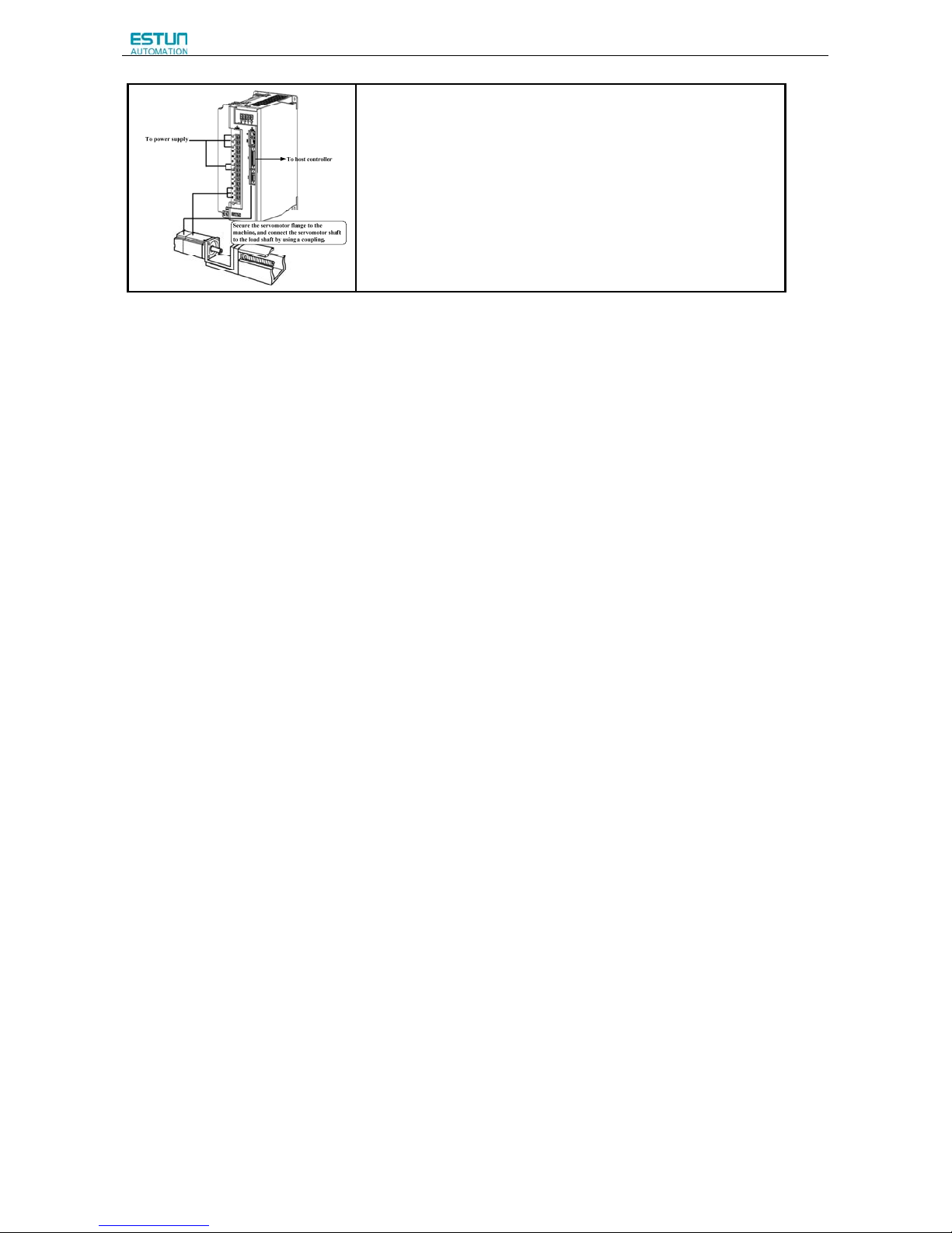
ProNet Series AC Servo User's Manual
- 59 -
■Purpose
Perform the trial operation with the servomotor
connected to the machine. The servo drive is adjusted to match the
machine characteristics.
·Servomotor speed and machine travel distance.
·Set the necessary parameters.
(Please refer to step 9-11)
Page 62
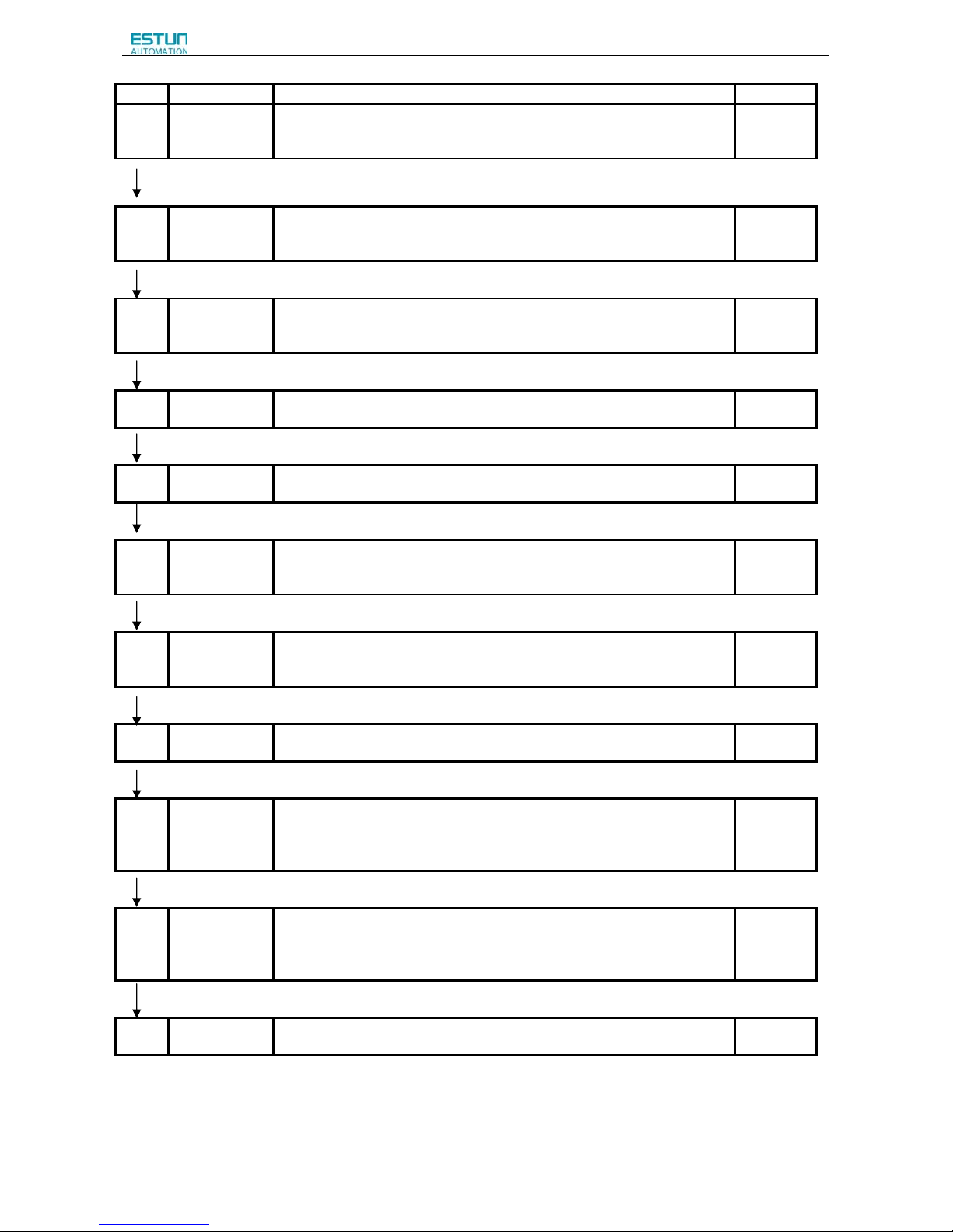
ProNet Series AC Servo User's Manual
- 60 -
Step Item Description Reference
1 Installation
Install the servomotor and servo drive according to the installation
conditions. (Do not connect the servomotor to the machine because the
servomotor will be operated first under the no-load condition for checking.)
-
2 Wiring
Connect the power supply circuit (L1, L2 and L3), servomotor wiring (U, V,
W), I/O signal wiring (CN1), and encoder wiring (CN2). But during (1) Trial
Operation for Servomotor Without Load, disconnect the CN1 connector.
-
3
Turn the power
ON
Turn the power ON. Using the panel operator to make sure that the servo
drive is running normally. If using a servomotor equipped with an absolute
encoder, please perform the setup for the absolute encoder.
-
4
Execute JOG
operation
Execute JOG operation with the servomotor alone under the no-load
condition.
JOG
Operation
5
Connect input
signals
Connect the input signals (CN1) necessary for trial operation to the
servo drive.
-
6
Check input
signals
Use the internal monitor function to check the input signals.
Turn the power ON, and check the emergency stop, brake, overtravel, and
other protective functions for the correct operation.
-
7
Input the
Servo-ON
signal
Input the Servo-ON signal, and turn ON the servomotor.
Host
Reference
8 Input reference
Input the reference necessary for control mode, and check the servomotor
for correct operation.
Host
Reference
9
Protective
operation
Turn the power OFF, and connect the servomotor to the machine.
If using a servomotor equipped with an absolute encoder, set up the absolute
encoder and make the initial settings for the host controller to match the
machine’s zero position.
-
10
Set necessary
parameters.
Using the same procedure as you did to input a reference in step 8,operate
the servomotor via the host controller and set the parameter to make sure
the machine’s travel direction, travel distance, and travel speed all
correspond to the reference.
Host
Reference
11 Operation The servomotor can now be operated. Adjust the servo gain if necessary.
Host
Reference
Page 63

ProNet Series AC Servo User's Manual
- 61 -
4.1.1 Trial Operation for Servomotor Without Load
·Release the coupling between the servomotor and the machine, and secure only the servomotor without a load.
·To prevent accidents, initially perform the trial operation for servomotor under no-load conditions (with all couplings
and belts disconnected).
In this section, confirm the cable connections of the main circuit power supply, servomotor and encoder. Incorrect wiring is
generally the reason why servomotors fail to operate properly during the trial operation.
Confirm the wiring, and then conduct the trial operation for servomotor without load according to the following steps.
Step Description Check Method and Remarks
1
Secure the servomotor.
Secure the servomotor flange to the machine in order
to prevent the servomotor from moving during
operation.
Do not connect the servomotor shaft to the machine.
The servomotor may tip over during rotation.
2
Check the power supply circuit, servomotor, and encoder
wiring.
With the I/O signal connector (CN1) disconnected,
check the power supply circuit and servomotor wiring.
Refer to 3.1 Main Circuit Wiring.
3
Turn ON the control power supply and main circuit power
supply.
Normal Display
Alternate Display
Example of Alarm Display
If the power is correctly supplied, the panel operator
display on the front panel of the servo drive will appear
as shown on the left. The display on the left indicates
that forward run prohibited (P-OT) and reverse run
prohibited (N-OT).
If an alarm display appears, the power supply circuit,
servomotor wiring, or encoder wiring is incorrect. If an
alarm is displayed, turn OFF the power, find the
problem, and correct it.
4
When using a servomotor with a brake, release the brake
first before driving the servomotor.
When using a servomotor equipped with an absolute
encoder, the encoder setup is required before driving the
servomotor.
Please refer to 4.3.4 Setting for Holding Brakes
Please refer to 4.5 Operating Using Speed Control
with Analog Reference
Page 64
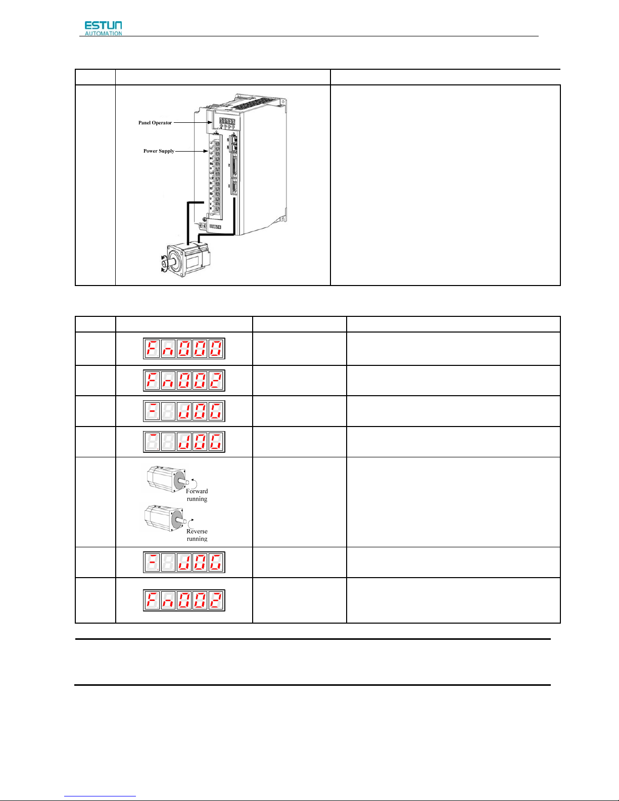
ProNet Series AC Servo User's Manual
- 62 -
Step Description Check Method and Remarks
5
Use the panel operator to operate the servomotor with
utility function Fn002 (JOG Mode Operation)Check that
the servomotor rotates in the forward direction by pressing
the INC key, and reverse direction by pressing the DEC
key.
The operation is completed when the operation is
performed as described below and the alarm display does
not appear.
Complete the Fn002 (JOG Mode Operation) and turn OFF
the power.
For the operation method of the panel operator, refer to
Chapter 5 Panel Operator
The servomotor speed can be changed using the Pn305
(JOG Speed).The factory setting for JOG speed is
500rpm.
JOG Mode Operation (Fn002)
Step Display after operation Panel operator Description
1
MODE key
Press the MODE key to select the function
mode.
2
INC or DEC key
Press the INC key or DEC key to select
Fn002.
3
ENTER key
Press the ENTER key, and the servomotor will enter
JOG operation mode.
4
MODE key
Press the MODE key. This will turn ON the power to
the servomotor.
5
INC or DEC key
The servomotor will run in forward direction when INC
key is pressed or in reverse direction when DEC key
is pressed. The servomotor will operate as long as the
key is pressed.
6
MODE key
Press the MODE key. This will turn OFF the power to
the servomotor.
7
ENTER key
Press the ENTER key to return to the Fn002 display
of the utility function mode. Now, the servo drive is
OFF.
Note:
The servomotor’s rotation direction depends on the setting of parameter Pn001.0 (Direction Selection).
The example above describes operation with Pn001.0 in the factory setting.
Page 65
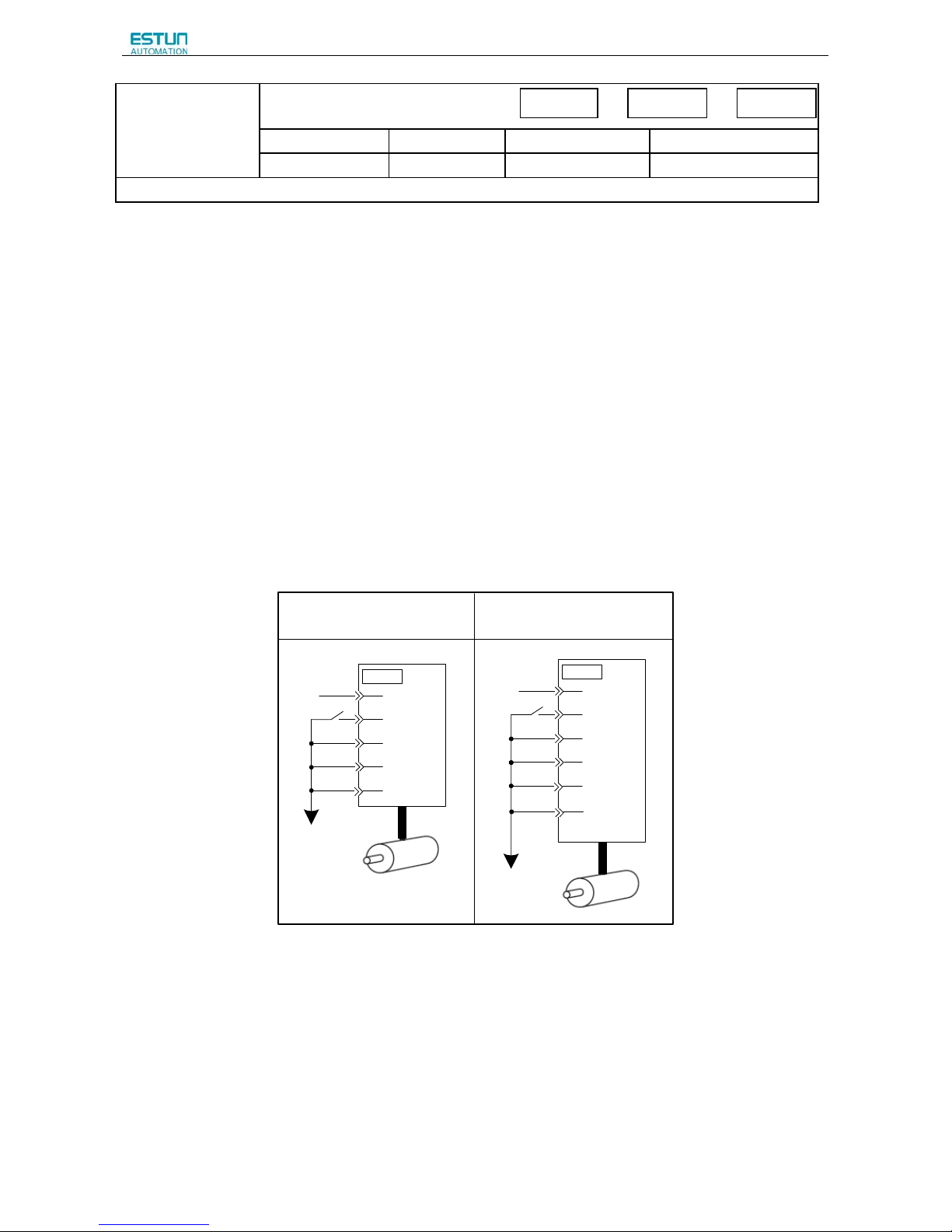
ProNet Series AC Servo User's Manual
- 63 -
Pn305
JOG Speed
Setting Range Setting Unit Factory Setting Setting Validation
0~6000 rpm 500 Immediately
Set the utility function Fn002 (JOG Mode Operation) to the reference value of servomotor speed.
The servomotor can be operated using only the panel operator without reference from the host controller.
Please note that the Forward Run Prohibited (P-OT) and Reverse Run Prohibited (N-OT) signals are invalid during JOG
mode operation.
4.1.2 Trial Operation for Servomotor without Load from Host Reference
Check that the servomotor move reference or I/O signals are correctly set from the host controller to the servo drive.
Also check the wiring and polarity between the host controller and servo drive, and the servo drive operation settings are
correct. This is the final check before connecting the servomotor to the machine.
(1)Servo ON Command from the Host
The following circuits are required: External input signal circuit or equivalent.
0V
+24V
/S-ON
P-OT
N-OT
V-REF
13
30
17
16
14
CN1
13
1
17
16
14
CN1
32
+24V
/S-ON
P-OT
N-OT
PULS
SIGN
Speed Control
(Standard Setting)
[Pn005=H.□□0□]
Position Control
[Pn005=H.□□1□]
0V
Speed Position
To rque
Page 66
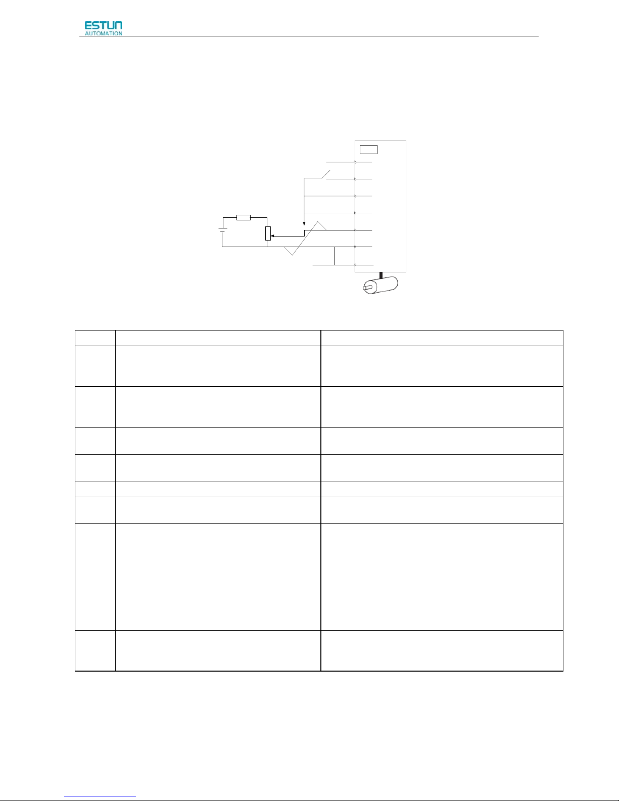
ProNet Series AC Servo User's Manual
- 64 -
(2)Operating Procedure in Speed Control Mode (Pn005=H.□□0□)
The following circuit is required: External input signal circuit or equivalent.
+24V
/S-ON
P-OT
N-OT
1
17
16
14
13
2
3
V-REF+
V-REF-
GND
CN1
V-REF+
V-REF-
0V
Servodrive
Max. Voltage (12V)
Step Description Check Method and Remarks
1
Check the power and input signal circuits again,
and check that the speed reference input (voltage
between the V-REF+ and V-REF-) is 0V.
Refer to the above figure for the input signal circuit.
2 Turn ON the servo ON (/S-ON) input signal.
If the servomotor rotates at an extremely slow speed, refer to
4.5.3 Adjusting Reference Offset, and use the reference
voltage offset to keep the servomotor from moving.
3
Generally increase the speed reference input
voltage between V-REF+ and V-REF- from 0 V.
The factory setting is 6V/rated rotation speed.
4
Check the speed reference input to the servo drive
(Un001[rpm])
Refer to 5.1.6 Operation in Monitor Mode.
5 Check the Un000 (motor speed [rpm]) Refer to 5.1.6 Operation in Monitor Mode.
6
Check that the Un001 and Un000 values in steps 4
and 5 are equal.
Change the speed reference input voltage and check that
Un001 and Un000 are equal for multiple speed references.
7
Check the speed reference input gain and
servomotor rotation direction.
Refer to the following equation to change the speed reference
input gain (Pn300).
Un001=(V-REF Voltage)[V]×Pn300
To change the servomotor rotation direction without changing
polarity for speed reference input voltage, refer to 4.3.2
Switching the Servomotor Rotation Direction.
Perform the operation from step 2 again after the servomotor
rotation direction is changed.
8
When the speed reference input is set to 0 V and
servo OFF status enters, trial operation for
servomotor without load is completed.
Page 67

ProNet Series AC Servo User's Manual
- 65 -
■ When Position Control is configured at the Host
When the servo drive conducts speed control and position control is conducted at the host controller, perform the
operation below,following the operation in Operation Procedure in Speed Control Mode (Pn005=H.□□0□).
Step Description Check Method and Remarks
9
Check the input signal circuit again, and check that
the speed reference input (between the V-REF+ and
V-REF-) is 0 V.
Refer to the above figure for input signal circuit.
10
Turn the servo ON input signal (/S-ON) ON.
If the servomotor rotates at an extremely slow speed,
refer to 4.5.3 Adjusting Reference
Offset, and use the reference voltage offset to keep the
servomotor from moving.
11
Send the command for the number of servomotor
rotations. Check the sent number of rotations, the
actual number of rotations by visual inspection, and
the Un004 (rotation angle)[pulse]
Refer to 5.1.6 Operation in Monitor Mode for how it is
displayed.
Un004(rotation angle)[pulse]: The number of pulses
from the zero point.
12
If the sent number of rotations and actual number of
rotations in step 11 are not equal, correctly set the
Pn200 (PG divided ratio) outputting the encoder pulse
from the servo drive.
Refer to 4.5.8 Encoder Signal Output for how to set
PG divided ratio (Pn200[P/Rev]):The
number of encoder pulses per revolution.
13
When the speed reference input is set to 0 V and
servo OFF status is entered, the trial operation for
position control with the host controller is completed.
—
Page 68

ProNet Series AC Servo User's Manual
- 66 -
(3)Operating Procedure in Position Control Mode (Pn005=H.□□1□)
The following circuit is required: External input signal circuit or equivalent.
13
40
17
16
14
CN1
30
+24V
/S-ON
P-OT
N-OT
CLR
PULS
31
32
33
/PULS
SIGN
/SIGN
Servodrive
Reference pulse
according to parameter
Pn004.2 setting.
Pulse reference
Step Description Check Method and Remarks
1
Match the reference pulse form with the pulse output form
from the host controller.
Set the reference pulse form with Pn004.2.
2
Set the reference unit and electronic gear ratio so that it
coincides with the host controller setting.
Set the electronic gear ratio with Pn201(or
Pn203)/Pn202.
3 Turn the power and the servo ON input signal ON.
4
Send the slow speed pulse reference for the number of
servomotor rotation easy to check (for example, one
servomotor revolution) from the host controller in advance.
Set the servomotor speed to 100rpm for the
reference pulse speed because such speed is safe.
5
Check the number of reference pulses input to the servo
drive by the changed amount before and after the Un013 and
Un014(input reference pulse counter)[pulse] were executed.
Refer to 5.1.6 Operation in Monitor Mode for how
it is displayed.
6
Check whether the actual number of servomotor rotations
Un009、Un010 coincides with the number of input reference
pulses.
Refer to 5.1.6 Operation in Monitor Mode for how
it is displayed.
7
Check that the servomotor rotation direction is the same as
the reference.
Check the input pulse polarity and input reference
pulse form.
8
Input the pulse reference with the large number of
servomotor rotation from the host controller to obtain the
constant speed.
Set the servomotor speed to 100rpm for the
reference pulse speed because such speed is safe.
9
Check the reference pulse speed input to the servo drive
using the Un008 in Monitor Mode. (input reference pulse
speed)[rpm].
Refer to 5.1.6 Operation in Monitor Mode for how
it is displayed.
10
Check the servomotor speed using the Un000 in Monitor
Mode. (servomotor speed) [rpm].
Refer to 5.1.6 Operation in Monitor Mode for how
it is displayed.
11 Check the rotation of the servomotor shaft.
To change the servomotor rotation direction without
changing the input reference pulse form, refer to
4.3.2 Switching the Servomotor Rotation
Direction. Perform the operation from step 8 again
after the servomotor rotation direction is changed.
12
When the pulse reference input is stopped and servo OFF
status is entered, the trial operation for servomotor without
load in position control mode is complete.
—
Page 69
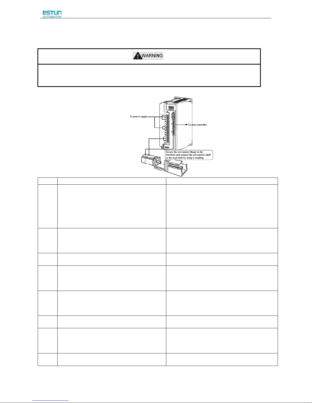
ProNet Series AC Servo User's Manual
- 67 -
4.1.3 Trial Operation with the Servomotor Connected to the Machine
·Follow the procedure below for trial operation precisely as given.
·Malfunctions that occur after the servomotor is connected to the machine not only damage the machine, but may
also cause an accident resulting in death or injury.
Follow the procedure below to perform the trial operation.
Step
Description Check Method and Remarks
1
Turn the power ON, and make the settings for the
mechanical configuration related to protective
functions such as overtravel and brake.
Refer to 4.3 Setting Common Basic Functions.
When a servomotor with brake is used, take advance
measures to prevent vibration due to gravity acting on
the machine or external forces before checking the
brake operation. Check that both servomotor and brake
operations are correct.
For details, refer to 4.3.4 Setting for Holding Brakes.
2
Set the necessary parameters for the control mode
used.
Refer to 4.5 Operating Using Speed Control with
Analog Reference, 4.6 Operating Using Position
Control, and 4.7 Operating Using Torque Control for
control mode used.
3
Connect the servomotor to the machine with the
coupling,etc.,while the power is OFF.
4
Check that the servo drive is servo OFF status and
then turn ON the power to the machine (host
controller). Check again that the protective function in
step 1 operates normally.
Refer to 4.3 Setting Common Basic Functions.
For the following steps, take advanced measures for an
emergency stop so that the servomotor can stop safely
when an error occurs during operation.
5
Perform trial operation with the servomotor connected
to the machine, following each section in 4.1.2 Trial
Operation for Servomotor without Load from Host
Reference.
Check that the trial operation is completed according to
the trial operation for servomotor without load. Also,
check the settings for machine such as reference unit.
6
Check the parameter settings for control mode used in
step 2.
Check that the servomotor rotates matching the
machine operating specifications.
7
Adjust the servo gain and improve the servomotor
response characteristics, if necessary.
The servomotor will not be broken in completely during
trial operation. Therefore, let the system run for a
sufficient amount of time to ensure that it is properly
broken in.
8
Thus, the trial operation with the servomotor
connected to the machine is complete.
Page 70
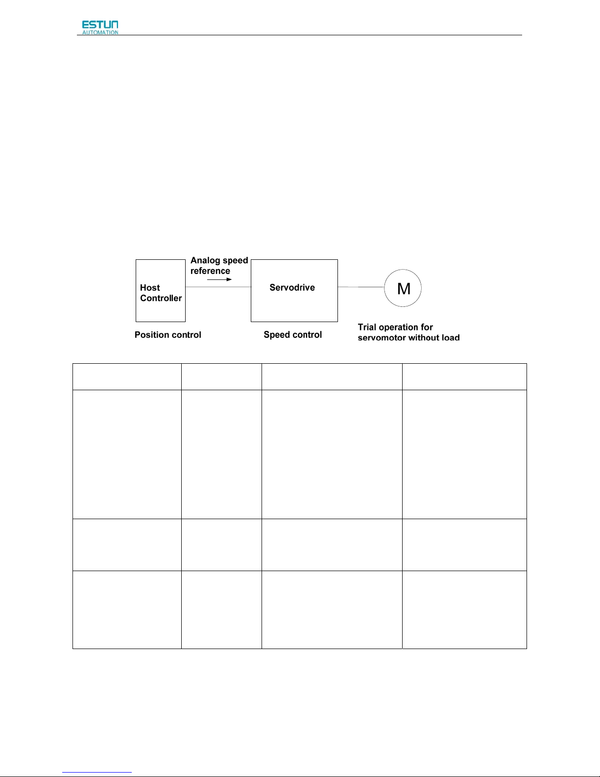
ProNet Series AC Servo User's Manual
- 68 -
4.1.4 Trial Operation for Servomotor with Brakes
Holding brake operation of the servomotor can be controlled with the brake interlock output (/BK) signal of the servo drive.
When checking the brake operation,take advance measures to prevent vibration due to gravity acting on the machine or
external forces. Check the servomotor operation and holding brake operation with the servomotor separated from the
machine. If both operations are correct, connect the servomotor to the machine and perform trial operation.
Refer to 4.3.4 Setting for Holding Brakes for wiring on a servomotor with brakes and parameter settings.
4.1.5 Position Control by Host Controller
As described above, be sure to separate the servomotor and machine before performing trial operation of the servomotor
without a load. Refer to the following table, and check the servomotor operation and specifications in advance.
Reference from the Host
Controller
Check Item Check Method Review Items
JOG Operation
(Constant speed reference
input from host controller)
Servomotor speed Check servomotor speed as
follows:
·Use the servomotor speed monitor
(Un000) on the panel operator.
·Run the servomotor at a low
speed.
For example, input a reference
speed of 60rpm, and check to see if
the servomotor makes one
revolution per second.
Check the parameter setting at
Pn300 to see if reference
speed gain is correct.
Simple positioning Number of
servomotor
rotation
Input a reference equivalent to one
servomotor rotation, and visually
check to see if the shaft makes one
revolution.
Check the parameter setting at
Pn200 to see if the number of
PG dividing pulses is correct.
Overtravel (P-OT and
N-OT Used)
Whether the
servomotor stops
rotating when
P-OT and
N-OT signals
are input.
Check to see if the servomotor
stops when P-OT and N-OT signals
are input during continuous
servomotor operation.
Review P-OT and N-OT wiring
if the servomotor does not
stop.
4.2 Control Mode Selection
The control modes supported by the ProNet series servo drives are described below.
Page 71

ProNet Series AC Servo User's Manual
- 69 -
Parameter Control Mode Reference Section
Pn005
H.□□0□
Speed Control (Analog voltage reference)
Controls servomotor speed using analog voltage speed reference.
Use in the following instances.
·To control speed
·For position control using the encoder feedback division output from
the servo drive to form a position loop in the host controller.
4.5
H.□□1□
Position Control (Pulse train reference)
Controls the position of the servomotor using pulse train position
reference.
Controls the position with the number of input pulses, and controls the
speed with the input pulse frequency.
Use when positioning is required.
4.6
H.□□2□
Torque Control (Analog voltage reference)
Controls the servomotor’s output torque with analog voltage torque
reference. Use to output the required amount of torque for operations
such as pressing.
4.7
H.□□3□
Speed Control (contact reference) Speed Control
(zero reference)
Use the three input signals /P-CON,/P-CL and /N-CL to control the
speed as set in advance in the servo drive.
Three operating speeds can be set in the servo drive. (In this case, an
analog reference is not necessary.)
4.8
H.□□4□
·
·
·
H.□□E□
These are swiching modes for using the four control methods
described above in combination. Select the control method switching
mode that best suits the application.
4.10
Page 72
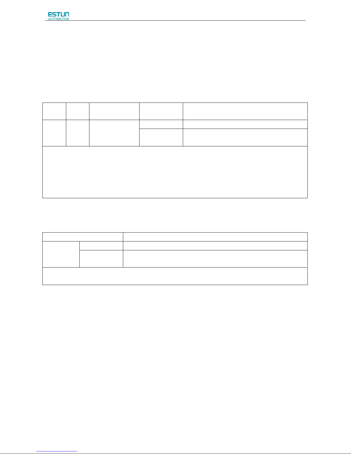
ProNet Series AC Servo User's Manual
- 70 -
4.3 Setting Common Basic Functions
4.3.1 Setting the Servo ON Signal
This sets the servo ON signal (/S-ON) that determines whether the servomotor power is ON or OFF.
(1)Servo ON signal(/S-ON)
Typ e N am e
Connector Pin
Number
Setting Meaning
Input /S-ON
CN1-14
(Factory setting)
ON(low level) Servomotor power ON. Servomotor can be operated.
OFF(high level)
Servomotor power OFF. Servomotor cannot be
operated.
■Important
Always input the servo ON signal before inputting the input reference to start or stop the servomotor.
Do not input the input reference first and then use the /S-ON signal to start or stop. Doing so will degrade internal
elements and may cause the servo drive to malfunction.
A parameter can be used to re-allocate the input connector number for the /S-ON signal. Refer to 3.2.2 I/O Signal Names
and Functions.
(2) Enabling/Disabling the Servo ON Signal
A parameter can be always used to set the servo ON condition. This eliminates the need to wire /S-ON, but care must be
taken because the servo drive can operate as soon as the power is turned ON.
Parameter Meaning
Pn000
b.□□□0 External S-ON signal enabled (Factory setting)
b.□□□1
External S-ON signal disabled, the servomotor excitation signal is
opened automatically after outputting the S-RDY signal.
After changing these parameters, turn OFF the main circuit and control power supplies, and then turn them
ON again to enable the new settings.
Page 73
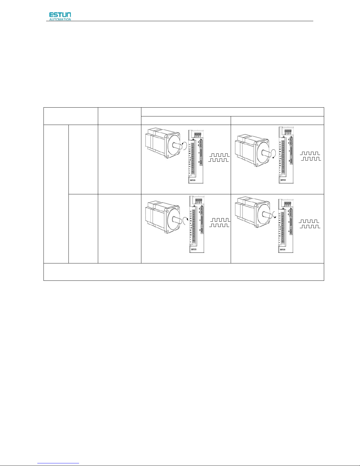
ProNet Series AC Servo User's Manual
- 71 -
4.3.2 Switching the Servomotor Rotation Direction
The rotation direction of the servomotor can be switched without changing the reference pulse to the servo drive or the
reference voltage polarity.
This causes the rotation the servo motor shaft is rotating to change. The output signal polarity, such as the encoder pulse
output and the analog monitor signal from the servo drive do not change.
The standard setting for “forward rotation” is counterclockwise as viewed from the servomotor load end.
Parameter Name
Reference
Forward reference Reverse reference
Pn001
b.□□□0
Standard setting
(CCW=forward)
(factory setting)
PBO
CCW
PAO
Encoder pulse di vision out put
PAO
PBO
CW
Encoder pul se divi sion ou tput
b.□□□1
Reverse rotation
mode
(CW=forward)
CW
PAO
PBO
Encoder pulse di visi on output
CCW
PAO
PBO
Encoder pulse divisi on output
The direction of P-OT and N-OT change. For Pn001=b.□□□0(standard setting), counterclockwise is P-OT. For
Pn001=b.□□□1(reverse rotation mode), clockwise is P-OT.
Page 74
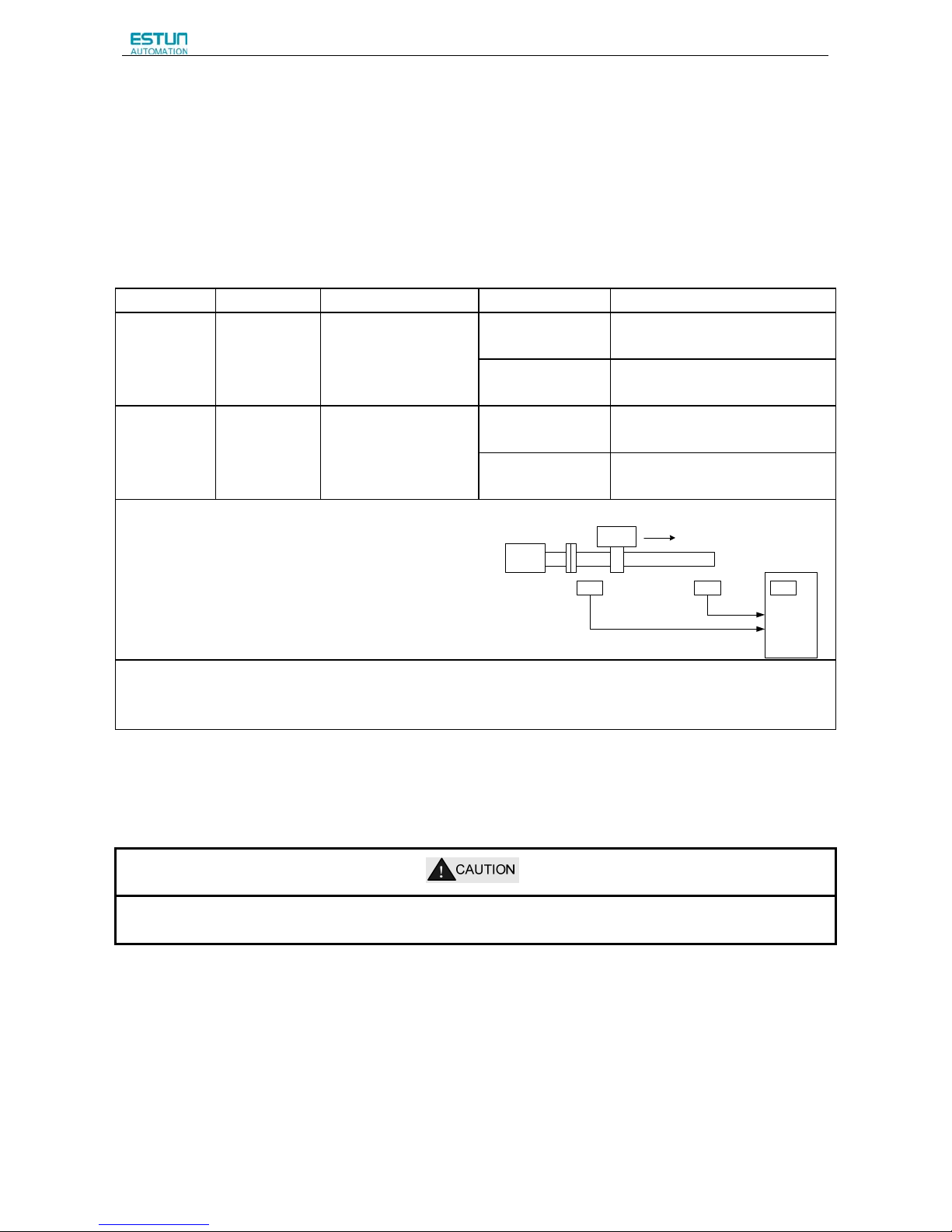
ProNet Series AC Servo User's Manual
- 72 -
4.3.3 Setting the Overtravel Limit Function
The overtravel limit function forces movable machine parts to stop if they exceed the allowable range of motion and turn
ON a limit switch.
(1)Connecting the overtravel signal
To use the overtravel function, connect the following overtravel limit switch to the corresponding pin number of servo drive
CN1 connector correctly.
Type Signal Name Pin No. Setting Meaning
Input P-OT
CN1-16
(factory setting)
ON(low level)
Forward rotation allowed. (Normal
operation status.)
OFF(high level)
Forward rotation prohibited.
(Forward overtravel)
Input N-OT
CN1-17
(factory setting)
ON(low level)
Reverse rotation (Normal operation
status.)
OFF(high level)
Reverse rotation prohibited.
(Reverse overtravel)
Connect limit switches as shown below to prevent damage
to the devices during linear motion.
Rotation in the opposite direction is possible during
overtravel.
For example, reverse rotation is possible during forward
overtravel.
Servomotor forward rotation direction.
Servodrive
Servomotor
Limit switch Limit switch
P-OT
N-OT
CN1
16
17
■Important
When using overtravel to stop the servomotor during position control, the position error pulses are present. A clear signal
(CLR) input is required to clear the error pulses.
When using the servomotor on a vertical axis, the workpiece may fall in the overtravel condition.
To prevent this, always set the zero clamp after stopping with Pn004.0=5.
Page 75

ProNet Series AC Servo User's Manual
- 73 -
(2)Enabling/Disabling the Overtravel Signal
A parameter can be set to disable the overtravel signal. If the parameter is set, there is no need to wire the overtravel input
signal.
Parameter Meaning
Pn000
b.□□0□ Inputs the forward rotation prohibited (P-OT) signal from
CN1-16 (factory setting).
b.□□1□ Disables the forward rotation prohibited (P-OT) signal. (Allows constant
forward rotation.)
b.□0□□ Inputs the reverse rotation prohibited (N-OT) signal from CN1-17.
(factory setting)
b.□1□□ Disables the reverse rotation prohibited (N-OT) signal. (Allows constant
reverse rotation.)
·Applicable control modes: Speed control, position control, and torque control.
·After changing these parameters, turn OFF the main circuit and control power supplies, and then turn them ON again to
enable the new settings.
·A parameter can be used to re-allocate input connector number for the P-OT and N-OT signals. Refer to 3.2.2 I/O Signal
Names and Functions.
(3)Selecting the Servomotor Stop Method
This is used to set the stop method when an overtravel(P-OT,N-OT)signal is input while the servomotor is operating.
Parameter Stop Mode
Mode After
Stopping
Meaning
Pn004
H.□□□0
Stop by dynamic
brake
Coast
Rapidlly stops the servo motor by dynamic braking(DB),
then places it into coast (power OFF) mode.
H.□□□1
Coast to a stop
Stops the servo motor in the same way as when the
servo is OFF (coast to a stop ), then places it into
coast(power OFF) mode.
H.□□□2
S-OFF
/Overtravel
Coast
Stops the servomotor by dynamic braking (DB) when
servo OFF, stops the servo motor by plug braking when
overtravel, and then places it into coast (power OFF)
mode.
H.□□□3
Makes the servomotor coast to a stop state when servo
OFF, stops the servomotor by plug braking when
overtravel, and then places it into coast (power OFF)
mode.
H.□□□4
Zero Clamp
Stops the servomotor by dynamic braking (DB) when
servo OFF, stops the servomotor by plug braking when
overtravel, and then places it into zero clamp mode.
H.□□□5
Makes the servomotor coast to a stop state when servo
OFF, stops the servomotor by plug braking when
overtravel, then places it into zero clamp mode.
Page 76
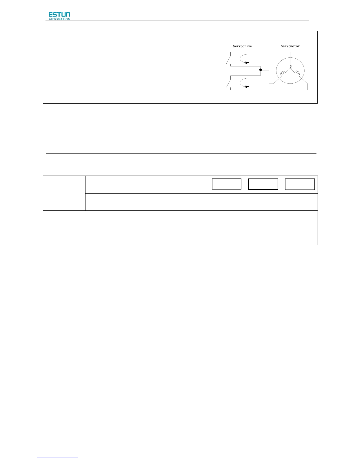
ProNet Series AC Servo User's Manual
- 74 -
·After changing these parameters, turn OFF the main circuit and control power
supplies, and then turn them ON again to enable the new settings.
·Stop by dynamic brake: Stops by using the dynamic brake (short circuiting its
electrical circuit).
·Coast to a stop: Stops naturally, with no brake, by using the friction resistance
of the servomotor in operation.
·Plug braking: Stops by using plug braking limit torque.
·Zero Clamp Mode: A mode forms a position loop by using the position
reference zero.
·Dynamic brake is an emergency stop function, and one of the general methods to cause a servomotor sudden stop.
·Dynamic brake suddenly stops a servomotor by shorting its electrical circuit.
·If the servomotor is frequently started and stopped by turning the power ON/OFF or using the servo ON signal(/S-ON),
the DB circuit will also be repeatedly operated, degrading the servo drive’s internal elements.
·Use the speed input reference and position reference to control the starting and the stopping of the servomotor.
(4)Setting the Stop Torque for Overtravel
Pn405
Plug braking torque limit`
Setting Range Setting Unit Factory Setting Setting Validation
0~300
1% 300 Immediately
· This sets the stop torque for when the overtravel signal (P-OT,N-OT) is input.
· The setting unit is a percentage of the rated torque. (the rated torque is 100%)
· The value large enough to be the servomotor maximum torque, 300% is set as the factory setting for plug braking limit
torque. However, the actual output plug braking limit torque is determined by servomotor ratings.
Speed
Position
To rque
Page 77
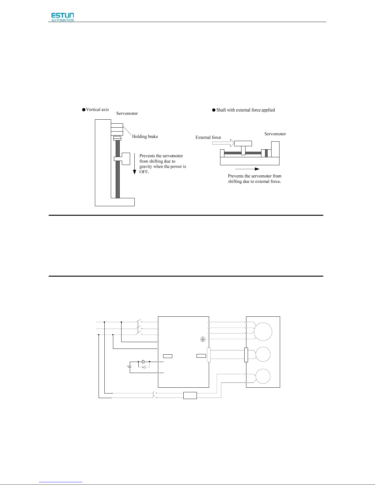
ProNet Series AC Servo User's Manual
- 75 -
4.3.4 Setting for Holding Brakes
The holding brake is used when the servo drive controls a vertical axis.
A servomotor with the brake option helps prevent movable parts from shifting due to gravity when power is removed from
the servo drive.
(Refer to 4.1.4 Trial Operation for Servomotor with Brakes.)
1. The servomotor with the built in brake, is a de-energization brake. It is used to hold the servomotor and cannot be used
as a braking purposes. Use the holding brake only to hold a stopped servomotor.
2. When operating using only a speed loop, turn OFF the servo and set the input reference to 0V when the brake is
applied.
3. When forming a position loop, do not use a mechanical brake while the servomotor is stopped because the servomotor
enters servolock status.
(1)Wiring Example
Use the servo drive sequence output signal /BK and the brake power supply to form a brake ON/OFF circuit.
The following diagram shows a standard wiring example.
M
PG
BK
U
V
W
L1
L2
L3
L1C
L2C
*1
*2
CN1
Power supply
R
S
T
Servodrive
BK-RY
(/BK+)
(/BK-)
+24V
BK-RY
Brake power supply
Yellow or blue
White
Red
Black
AC
DC
Servomotor with brake
BK-RY:Brake control relay
1*、2*:The output terminals allocated with Pn511.
CN2
Page 78

ProNet Series AC Servo User's Manual
- 76 -
(2)Brake interlock output
Type Signal Name Connector Pin Number Setting Meaning
Output /BK Must be allocated
ON(Low level) Releases the brake.
OFF(High level) Applies the brake.
This output signal controls the brake and is used only for a servomotor with a brake. This output signal is not used with
the factory setting.The output signal must be allocated by Pn511. It does not need to be connected for servomotor
without a brake.
(3)Allocating Brake Interlock Output (/Bk)
Brake interlock output (/BK) is not used with the factory setting.The output signal must be allocated.
Parameter
Connector Pin Number
Meaning
+ Terminal - Terminal
Pn511 H.□□□4 CN1-11 CN1-12
The /BK signal is output from output
terminal CN1-11,12.
Pn511 H.□□4□ CN1-5 CN1-6
The /BK signal is output from output
terminal CN1-5,6.
Pn511 H.□4□□ CN1-9 CN1-10
The /BK signal is output from output
terminal CN1-9,10.
■Important
When set to the factory setting, the brake signal is invalid.
For the allocation of servo drive output signals other than /BK signal, refer to 3.2.2 I/O Signal Names and Functions.
Parameter Pn511 description as following:
0 /COIN(/V-CMP)output
1 /TGON rotation detecting output
2 /S-RDY servo drive get ready output
3 /CLT torque limit output
4 /BK brake interlock output
5 /PGC encoder C pulse output
6 OT overtravel signal output
7 /RD servo enabled motor excitation output
8 /HOME home completion output
9 /TCR Torque Detection Output
Related parameter:
Parameter
No.
Name Unit
Setting
Range
Default
Pn505 Servo ON waiting time ms -2000~2000 0
Pn506 Basic waiting flow 10ms 0~500 0
Pn507 Brake waiting speed rpm
10~100
100
Pn508 Brake waiting time 10ms
10~100
50
Page 79
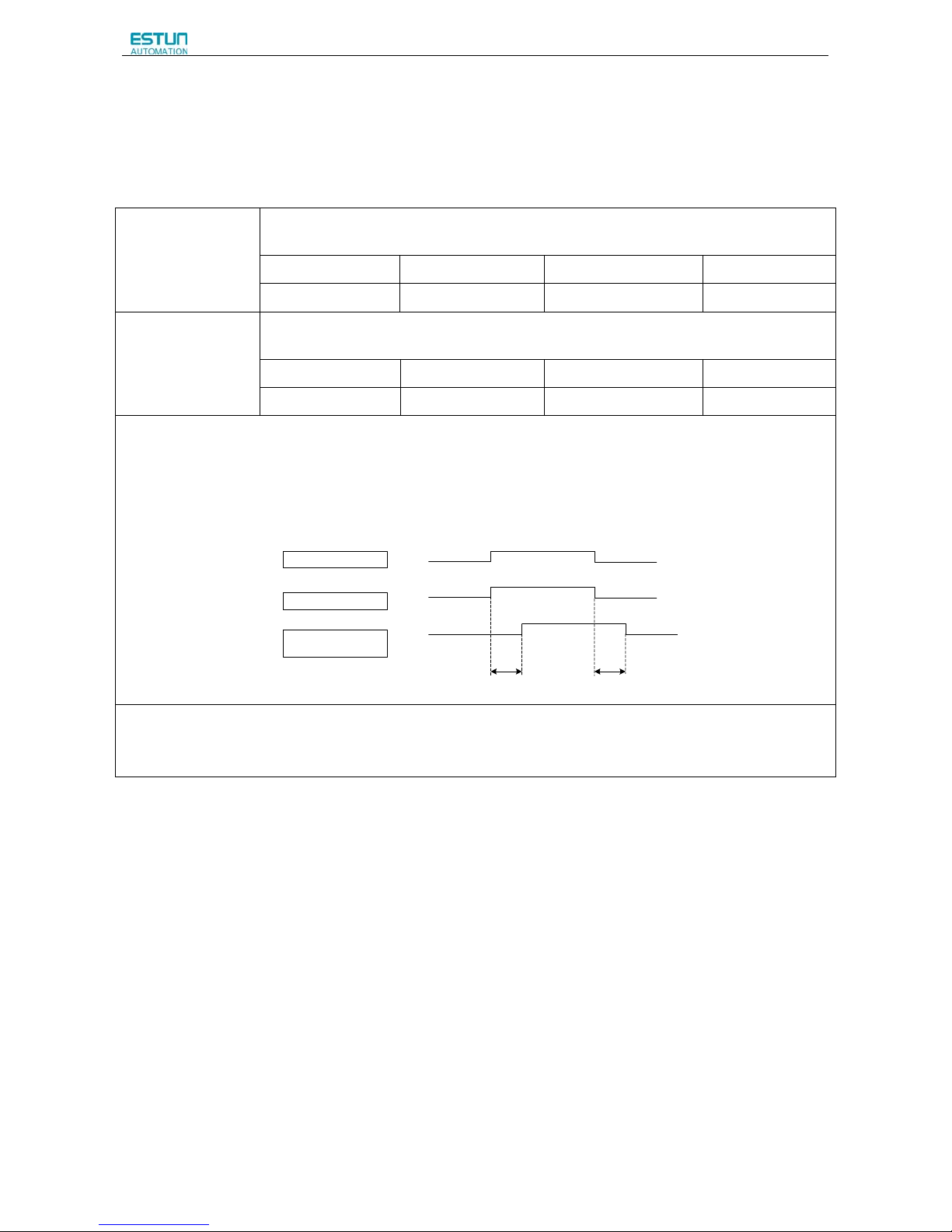
ProNet Series AC Servo User's Manual
- 77 -
(4)Setting the Brake ON/OFF Timing after the Servomotor Stops
With the factory setting, the /BK signal is output at the same time as the servo is turned OFF. The servo OFF timing can be
changed with a parameter.
Pn505
Servo ON waiting time
Setting Range Setting Unit Factory Setting Setting Validation
-2000~2000 ms 0 Immediately
Pn506
Basic waiting flow
Setting Range Setting Unit Factory Setting Setting Validation
0~500 10ms 0 Immediately
·When using the servomotor to control a vertical axis, the machine movable parts may shift slightly depending on the
brake ON/ OFF timing due to gravity or an external force. By using this parameter to delay turning the servo ON/ OFF, this
slight shift can be eliminated.
·For details on brake operation while the servomotor is operating, refer to (5) Setting the Brake ON/ OFF Timing When
Servomotor Running in this section.
■Important
·The servomotor will turn OFF immediately when an alarm occurs, regardless of the setting of this parameter.
·The machine movable part may shift due to gravity or external force during the time until the brake operates.
Servo ON
Servo OFF
Brake released
Using brakes
brake
Power to
servomotor
No power to
servomotor
Pn506
Pn505
/S-ON (CN1-14)
/BK Output
Power to Servomotor
Power to
servomotor
Brake released
Servo ON
Page 80

ProNet Series AC Servo User's Manual
- 78 -
(5)Setting the Brake ON/OFF Timing When Servomotor Running
The following parameters can be used to change the /BK signal output conditions when a stop reference is output during
servomotor operation due to the servo OFF or an alarm occuring.
Pn507
Brake Waiting Speed
Setting Range Setting Unit Factory Setting Setting Validation
10~100 1rpm 100 Immediately
Pn508
Brake Waiting Time
Setting Range Setting Unit Factory Setting Setting Validation
10~100 10ms 50 Immediately
/BK Signal Output Conditions When Servomotor Running
The /BK signal goes to high level (brake ON) when either of the following conditions is satisfied:
· When the servomotor speed falls below the level set in Pn507 after servo OFF.
· When the time set in Pn508 is exceeded after servo OFF.
4.3.5 Instantaneous Power Loss Settings
Determines whether to continue operation or turn the servo OFF when the power supply voltage to the servo drive main
circuit is instantaneously interrupted.
Parameter Signal Name and Meaning
Pn000
b.0□□□
Continue operation when the power supply voltage to servo drive main circuit is
instantaneously interrupted.
b.1□□□
An alarm occurs when the power supply voltage to servo drive main circuit is
instantaneously interrupted.
Speed Position
To rque
Speed
Position To rque
Pn508
Brake held
Brake released
/BK Output
Servomotor Speed
/S-ON input
or alarm or
power OFF
Servo ON
Servo OFF
Servomotor stopped
by applying DB or
coasting.
(Pn004.0)
Pn507
Page 81
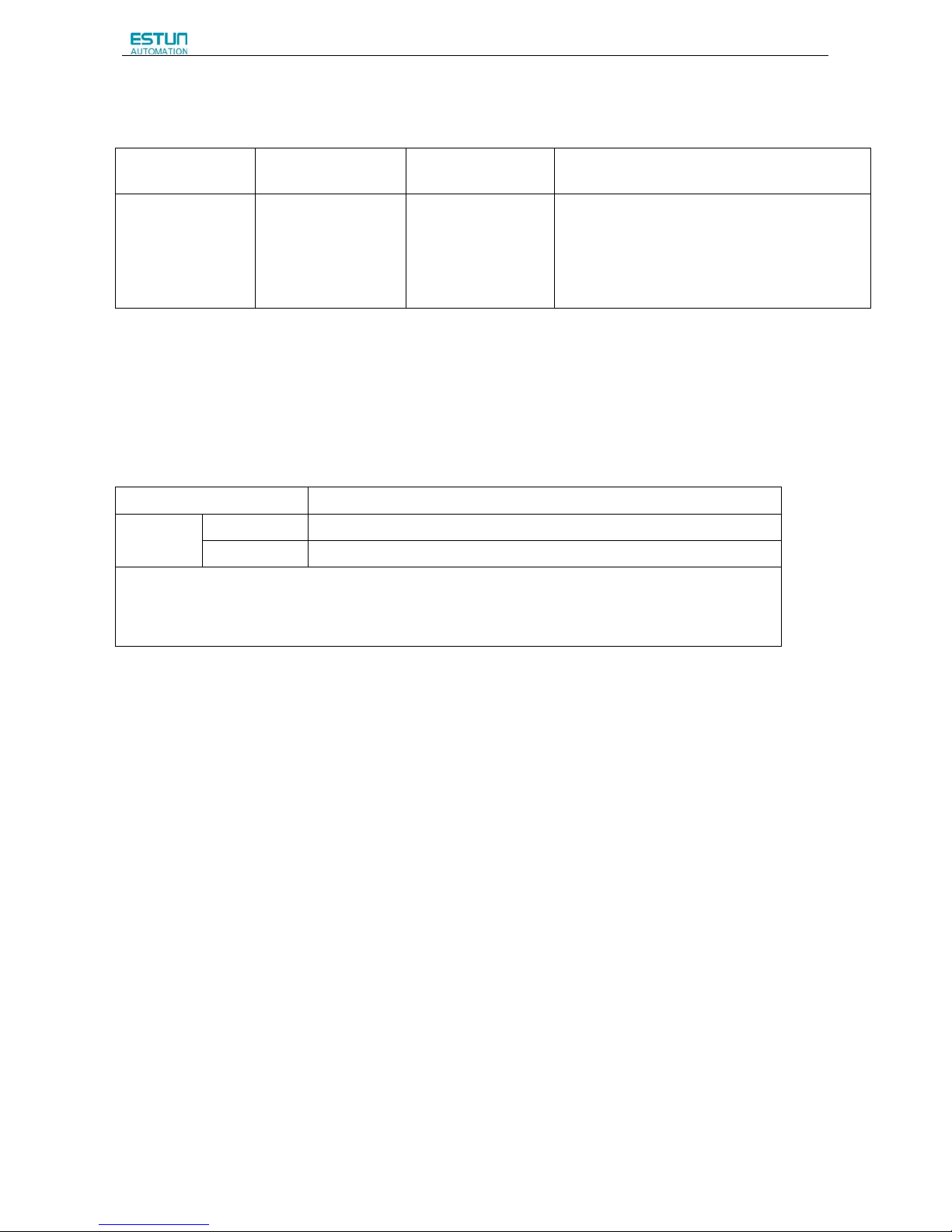
ProNet Series AC Servo User's Manual
- 79 -
4.4 Absolute Encoders
Absolute Encoder
Type
Resolution
Output Range of
Multiturn Data
Action when limit is exceeded
ProNet Series
16-bit/multiturn
17-bit/singleturn
-32768~+32767
·When the upper limit (+32767)is exceeded in the
forward direction, the multiturn data is -32768
·When the lower limit (-32768)is exceeded
in the reverse direction, the multiturn data is
+32767.
The absolute position can be read by the MODBUS protocol. In the actual control, the MODBUS protocol can read the
initial position when the servomotor is stopped (S-OFF), then the real-time position during the servomotor is running can
be found from the number of PG divided output pulses.
4.4.1 Selecting an Absolute Encoder
An absolute encoder can also be used as an incremental encoder.
Parameter Meaning
Pn002 b.□0□□ Use the absolute encoder as an absolute encoder. (Factory setting)
b.□1□□ Use the absolute encoder as an incremental encoder.
·The back-up battery is not required when using the absolute encoder as an incremental encoder.
·After changing these parameters, turn OFF the main circuit and control power supplies and then turn them ON
again to enable the new settings.
Page 82
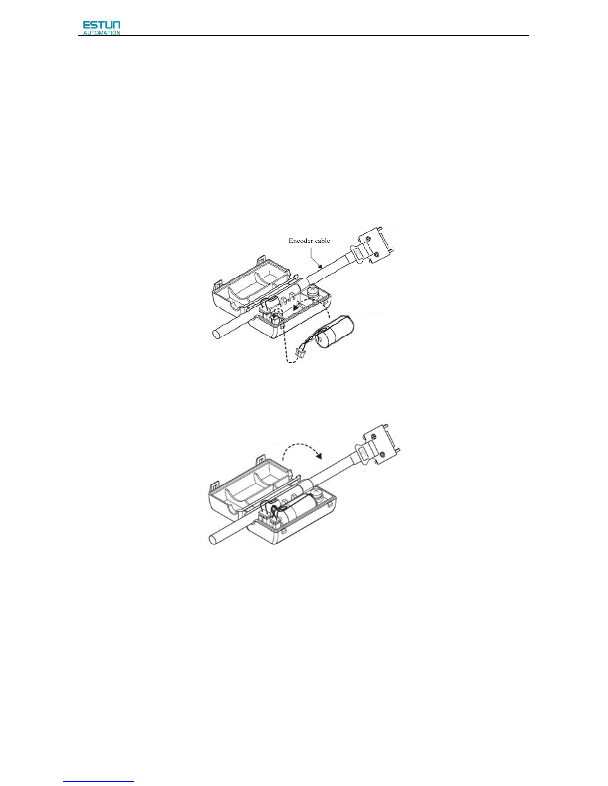
ProNet Series AC Servo User's Manual
- 80 -
4.4.2 Handling Battery
In order for the absolute encoder to retain position data when the power is turned OFF, the data must be backed up by a
battery.
Please purchase the special cable and battery case mabe by Estun if an absolute encoder is used.
Install the battary to the encoder cable:
A. Open the shell of the battery case.
B. Install the battery according to the following diagram.
C. Cover the shell of the battery case.
Page 83

ProNet Series AC Servo User's Manual
- 81 -
4.4.3 Replacing Battery
The servo drive will generate an absolute encoder battery alarm (A.48) when the battery voltage drops below about 3.1V.
Battery Replacement Procedure
1. Replace the battery with only the servo drive control power supply turned ON.
2. After replacing the battery, using the panel operator with utility function Fn011 to cancel the absolute encoder battery
alarm (A.48).
3. Turn ON the servo drive power back again. If it operates without any problems, the battery replacement has been
completed.
Note:
·The servo drive will generate an absolute encoder battery alarm (A.48) when the battery voltage drops below about 3.1V.
·If an absolute encoder battery alarm (A.47) occurred, it means the battery voltage drops below about 2.5V, and the
multiturn data is lost. Please reset the absolute encoder after changing the battery.
4.4.4 Absolute Encoder Setup(Fn010、Fn011)
Setting up the absolute encoder in the following cases.
·When starting the machine for the first time,set Pn002.2 to 0.
·When an encoder error alarm (A.45~A.48, A.51) is generated.
Use the panel operator in the servo drive for setup.
Note:
1. Encoder setup operation is only possible when the servo is OFF.
2. If the absolute encoder alarms(A.45~A.48,A.51 ) are displayed, cancel the alarm by using the same method as the
setup. They cannot be cancelled with the servo drive alarm reset input signal(/ALM-RST).
3. Any other alarms that monitor the inside of the encoder should be cancelled by turning OFF the power.
Page 84
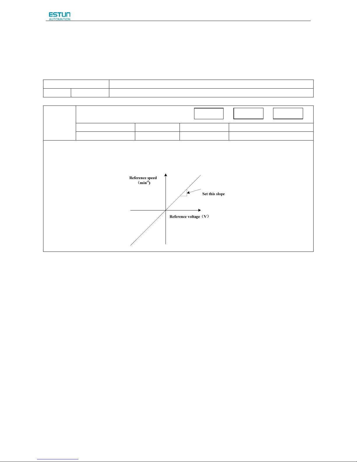
ProNet Series AC Servo User's Manual
- 82 -
4.5 Operating Using Speed Control with Analog Reference
4.5.1 Setting Parameters
Parameter Meaning
Pn005
H.□□0□
Control mode selection:Speed control(analog reference)(factory setting)
Pn300
Speed Reference Input Gain
Setting Range Setting Unit Factory Setting Setting Validation
0~3000
rpm/v 150 Immediately
Sets the analog voltage level for the speed reference (V-REF) necessary to operate the servomotor at the rated speed.
■EXAMPLE
Pn300=150:1V input is equivalent to the servomotor speed of 150rpm (factory setting).
Speed Position Torque
Page 85
ProNet Series AC Servo User's Manual
- 83 -
4.5.2 Setting Input Signals
(1)Speed Reference Input
Input the speed reference to the servo drive using the analog voltage reference to control the servomotor speed in
proportion to the input voltage.
Type Signal Name Connector Pin Number Name
Input
V-Ref+ CN1-1 Speed Reference Input
V-Ref- CN1-2 Speed Reference Input
The above inputs are used for speed control(analog voltage reference). (Pn005.1=0,4,7,9,A) Pn300 is used to set the
speed reference input gain.Refer to 4.5.1 Setting Parameters.
(2)Proportional Control Reference (/P-CON)
Tpye Signal
Connector Pin
Number
Setting Meaning
Input /P-CON CN1-15
ON(low level)
Operates the servo drive with proportional
control
OFF(high level)
Operates the servo drive with proportional
integral control.
/P-CON signal selects either the PI(proportional integral) or P(proportional) Speed Control Mode.
Switching to P control reduces servomotor rotation and minute vibrations due to speed reference input drift.
Input reference: At 0V, the servomotor rotation due to drift will be reduced, but servomotor rigidity (holding force) drops when
the servomotor is stopped.
Note: A parameter can be used to reallocate the input connector number for the /P-CON signal. Refer to 3.2.2 I/O Signal
Names and Functions.
Page 86
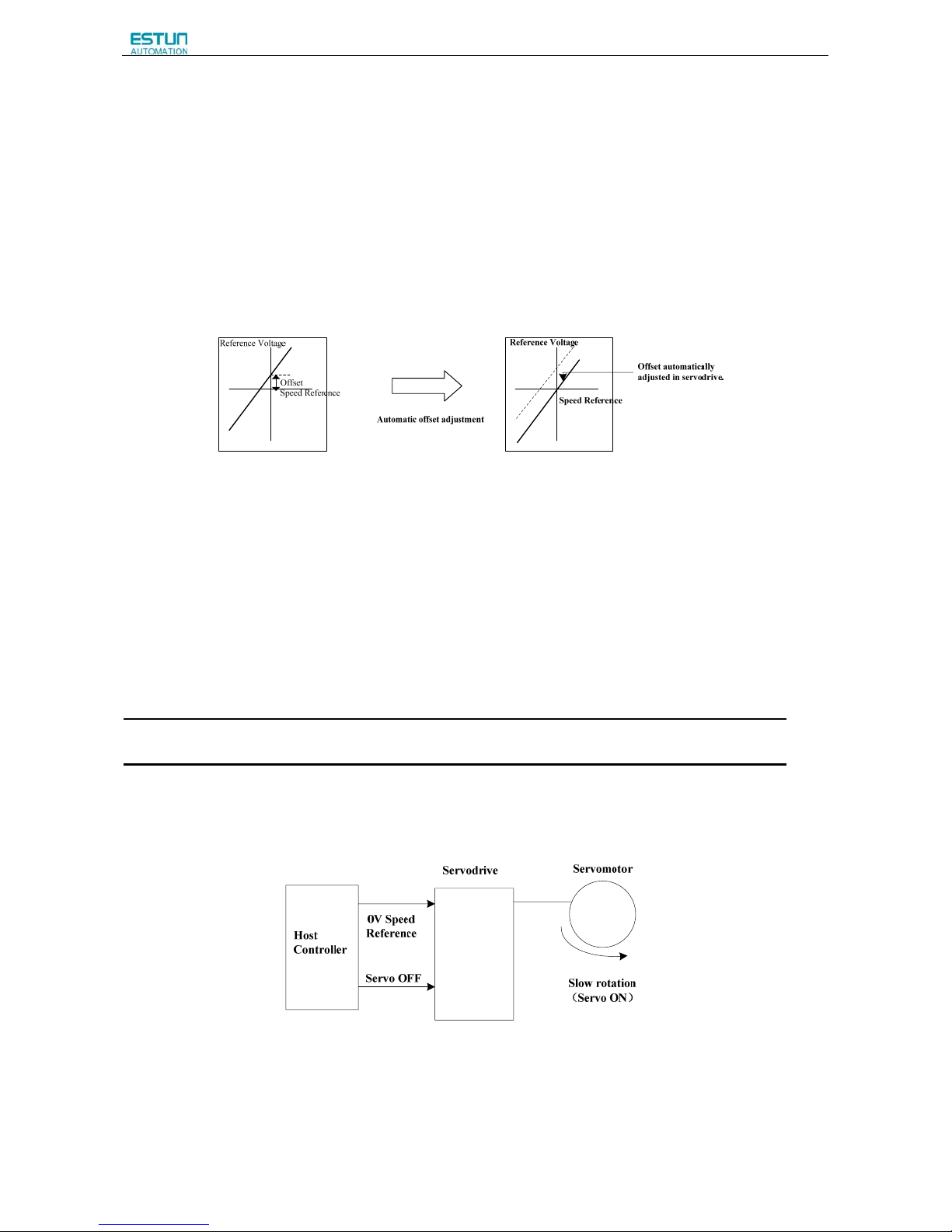
ProNet Series AC Servo User's Manual
- 84 -
4.5.3 Adjusting Reference Offset
When using the speed control, the servomotor may rotate slowly even if 0V is specified as the analog voltage reference.
This happens if the host controller or external circuit has a slight offset (in the unit of mV) in the reference voltage.
Adjustments can be done manually or automatically by using the panel operator. Refer to 5.2 Operation in Utility
Function Mode.
The servo drive automatically adjusts the offset when the host controller or external circuit has the offset in the reference
voltage.
After completion of the automatic adjustment, the amount of offset is stored in the servo drive. The amount of offset can be
checked in the speed reference offset manual adjustment mode (Fn004). Refer to 4.5.3 (2) Manual Adjustment of the
Speed Reference Offset.
(1) Automatic Adjustment of the Speed Reference Offset
The automatic adjustment of reference offset (Fn003) cannot be used when a position loop has been formed with a host
controller and the error pulse is changed to zero at the servomotor stop due to servolock. Use the speed reference offset
manual adjustment (Fn004) described in the next section for a position loop.
The zero-clamp speed control function can be used to force the servomotor to stop while the zero speed reference is
given. Refer to 4.5.7 Using the Zero Clamp Function.
Note:The speed reference offset must be automatically adjusted with the servo OFF.
Adjust the speed reference offset automatically in the following procedure.
1.Turn OFF the servo drive and input the 0V reference voltage from the host controller or external circuit.
2.Press the MODE key to select the utility function mode.
3.Press the INC or DEC key to select parameter Fn003.
Page 87
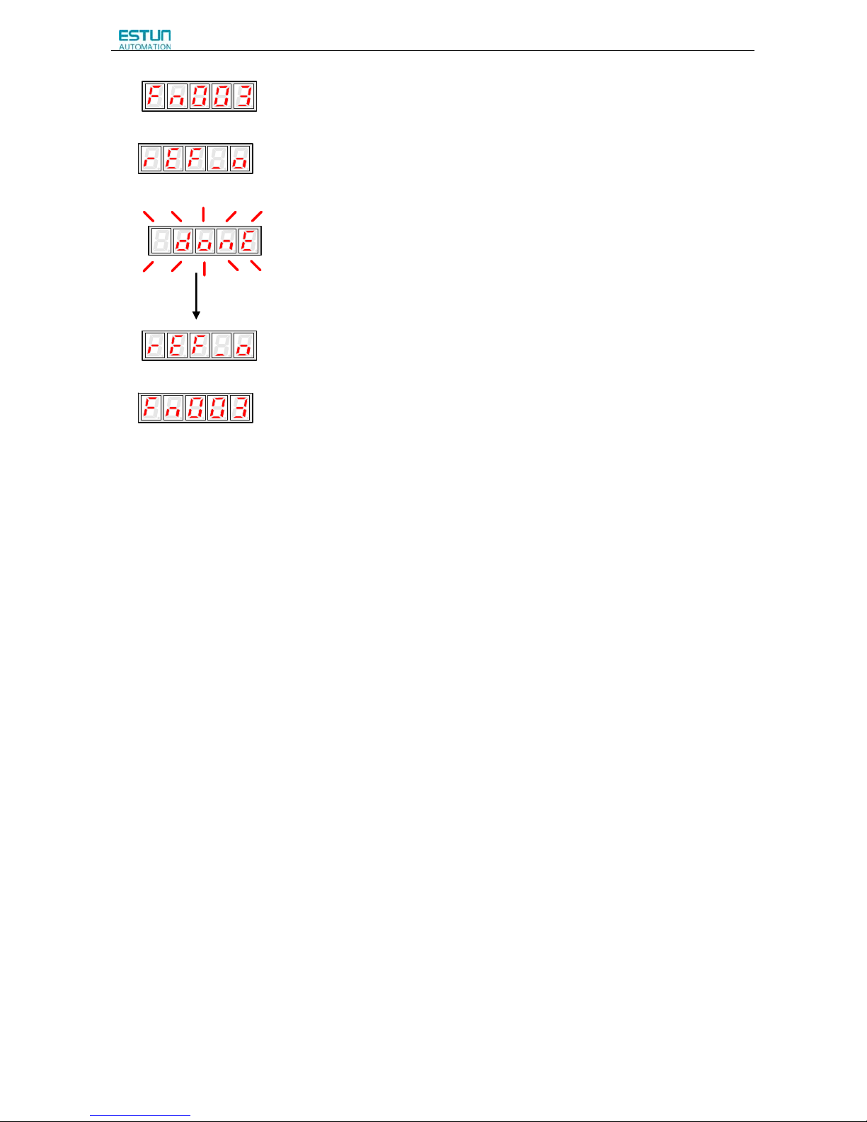
ProNet Series AC Servo User's Manual
- 85 -
4.Press the ENTER key to enter into the speed reference offset automatic adjustment mode.
5.Press the MODE key for more than one second, the reference offset will be automatically adjusted.
7.Press ENTER key to return to the Fn003 display of the utility function mode.
8.Thus, the speed reference offset automatic adjustment is completed.
Page 88
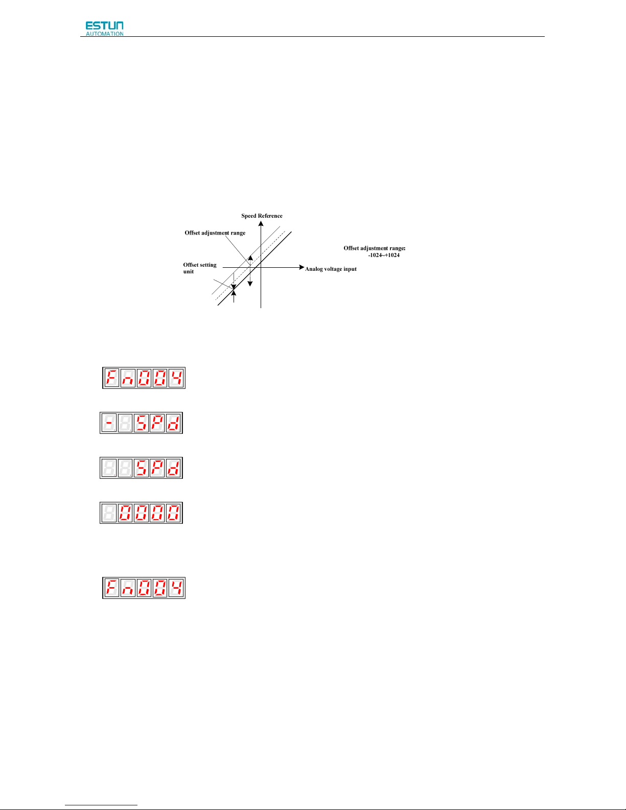
ProNet Series AC Servo User's Manual
- 86 -
(2)Manual Adjustment of the Speed Reference Offset
Use the speed reference offset manual adjustment (Fn004) in the following situations:
·If a loop is formed with the host controller and the postion error pulse is set to be zero when servolock is stopped.
·To deliberately set the offset to some value
·To check the offset data set in the speed reference offset automatic adjustment mode.
This function operates in the same way as the reference offset automatic adjustment mode (Fn003), except that the
amount of offset is directly input during the adjustment.
The offset setting range and setting unit are as follows:
Adjust the speed reference offset manually in the following procedure.
1. Press the MODE key to select the utility function mode.
2. Press the INC or DEC key to select parameter Fn004.
3. Press the ENTER key to enter into the speed reference offset manual adjustment mode.
4. Turn ON the servo ON (/S-ON) signal. The display will be shown as below.
5. Press the ENTER key for one second to display the speed reference offset amount.
6. Press the INC or DEC key to adjust the amount of offset.
7. Press the ENTER key for one second to return to the display in step 4.
8. Press the ENTER key to return to the Fn004 display of the utility function mode.
9. Thus, the speed reference offset manual adjustment is completed.
Page 89
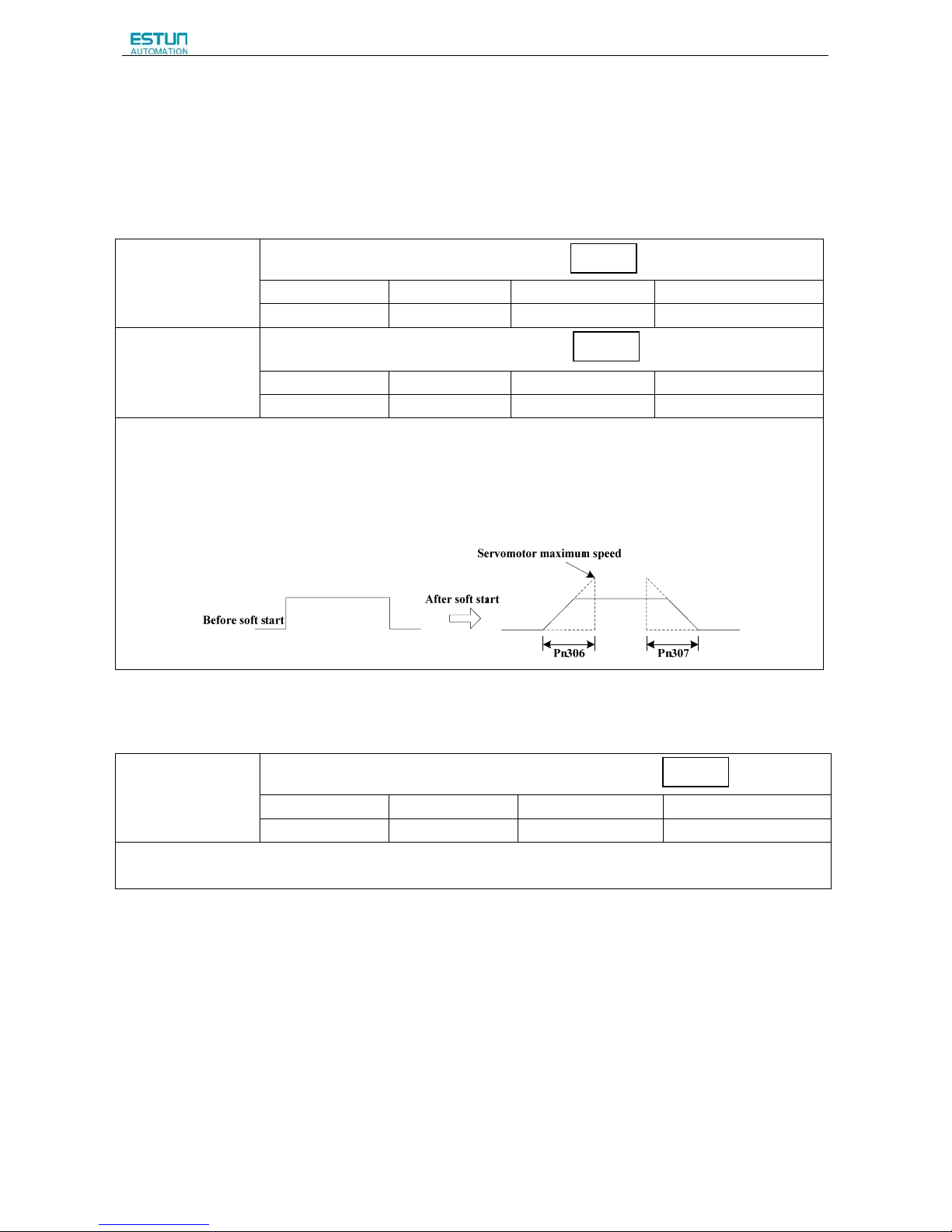
ProNet Series AC Servo User's Manual
- 87 -
4.5.4 Soft Start
The soft start function converts the stepwise speed reference inside the servo drive to a consistent rate of acceleration
and deceleration.
Pn310 can be used to select the soft start form:
0: Slope; 1: S curve; 2: 1
st
-order filter; 3: 2nd-order filter
Pn306
Soft Start Acceleration Time
Setting Range Setting Unit Factory Setting Setting Validation
0~10000
1ms 0 Immediately
Pn307
Soft Start Deceleration Time
Setting Range Setting Unit Factory Setting Setting Validation
0~10000
1ms
0
Immediately
The soft start function enables smooth speed control when inputting a stepwise speed reference or when selecting
internally set speeds. Set both Pn306 and Pn307 to “0” for normal speed control.
Set these parameters as follows:
· Pn306:The time interval from the time the servomotor starts until the servomotor maximum speed is reached.
· Pn307:The time interval from the time the servomotor is operating at the servomotor maximum speed until it stops.
4.5.5 Speed Reference Filter Time Constant
Pn308
Speed Reference Filter Time Constant
Setting Range Setting Unit Factory Setting Setting Validation
0~10000
1ms 0 Immediately
This smooths the speed reference by applying a 1
st
–order delay filter to the analog speed reference (V-REF) input. A
value that is too large, however, will decrease response.
Speed
Speed
Speed
Page 90
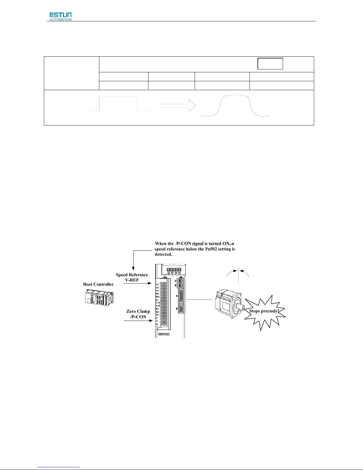
ProNet Series AC Servo User's Manual
- 88 -
4.5.6 S-curve Risetime
Pn309
S-curve Risetime
Setting Range Setting Unit Factory Setting Setting Validation
0~10000
1ms 0 Immediately
4.5.7 Using the Zero Clamp Function
(1)Zero Clamp Function
The zero clamp function is used for systems where the host controller does not form a position loop for the speed
reference input. When the zero clamp signal(/P-CON)is ON, a position loop is formed inside the servo drive as soon as
the input voltage of the speed reference (V-REF) drops below the servomotor zero clamp speed. The servomotor ignores
the speed reference and quickly stops and locks the servomotor.
The servomotor is clamped within ±1 pulse when the zero clamp function is turned ON, and will still return to the zero
clamp position even if it is forcibly rotated by an external force.
Speed
Page 91
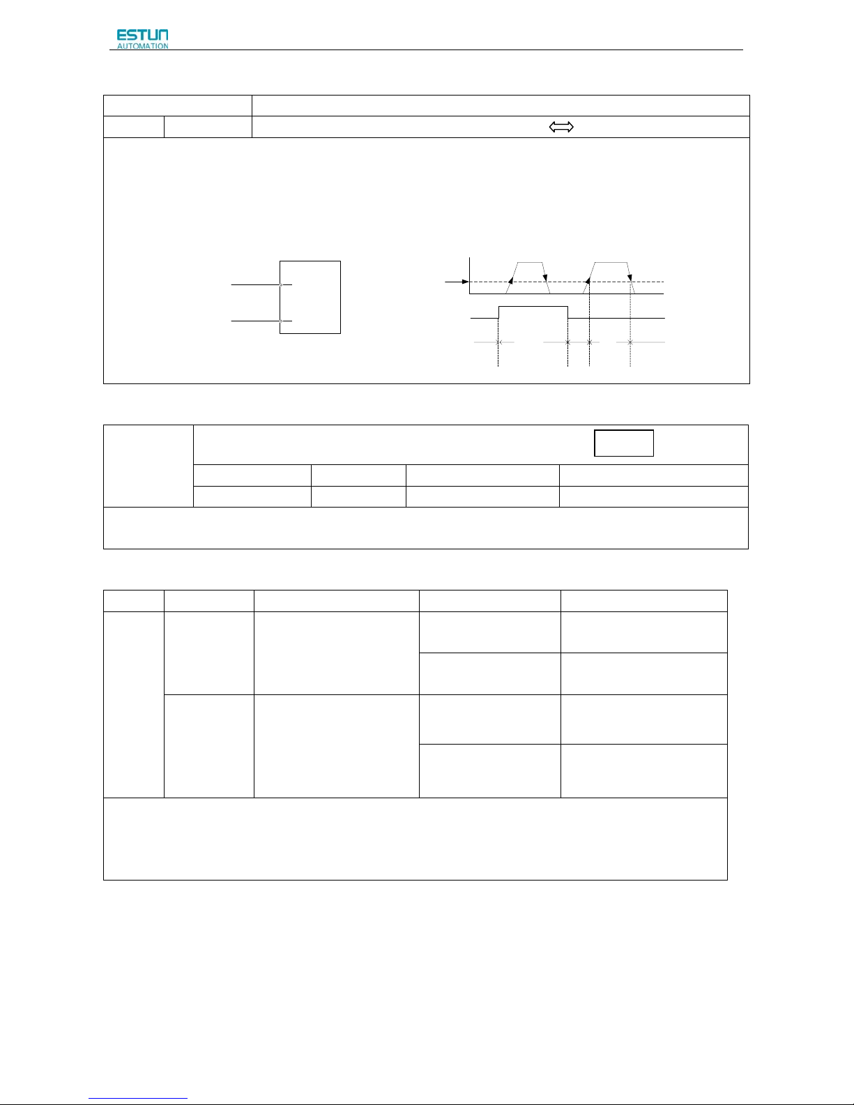
ProNet Series AC Servo User's Manual
- 89 -
(2)Parameter Setting
Parameter Meaning
Pn005
H.□□A□
Control mode: Speed control(analog voltage reference) Zero Clamp
Zero Clamp Conditions:
Zero clamp is performed with Pn005=H.□□A□ when the following two conditions are both satisfied:
·/P-CON is ON (low level)
·Speed reference (V-REF) drops below the setting in Pn502.
CN1
1
15
V-REF
/P-CON
Speed reference
Zero clamp
Servodrive
“V-REF”speed reference
Time
Speed
Preset value for zero
clamping Pn502
Open(OFF) Closed(ON)
“/P-CON”input
Zero clamp is performed.
ON
OFF OFF
ON
ON
Pn502
Zero clamp speed
Setting Range Setting Unit Factory Setting Setting Validation
0~3000
rpm 10 Immediately
Sets the servomotor speed at which the zero clamp is performed if zero clamp speed control(Pn005=H.□□A□) is
selected. Even if this value is set higher than the maximum speed of the servomotor, the maximum speed will be used.
(3)Input Signal Setting
Type Signal Name Connector Pin Number Setting Meaning
Input
/P-CON CN1-15
ON(low level)
Zero clamp function
ON(enabled)
OFF(high level)
Zero clamp function
OFF(disabled)
/ZCLAMP
Not including this setting in
the default setting,please
choose terminal output by
setting parameter
Pn509,Pn510
ON(low level)
Zero clamp function
ON(enabled)
OFF(high level)
Zero clamp function
OFF(disabled)
/P-CON and /ZCLAMP are the input signals to switch to the zero clamp function.
■Important
In speed control (analog voltage reference) mode,when /ZCLAMP is allocated to an output terminal,zero clamp
function is enabled.
Speed
Page 92
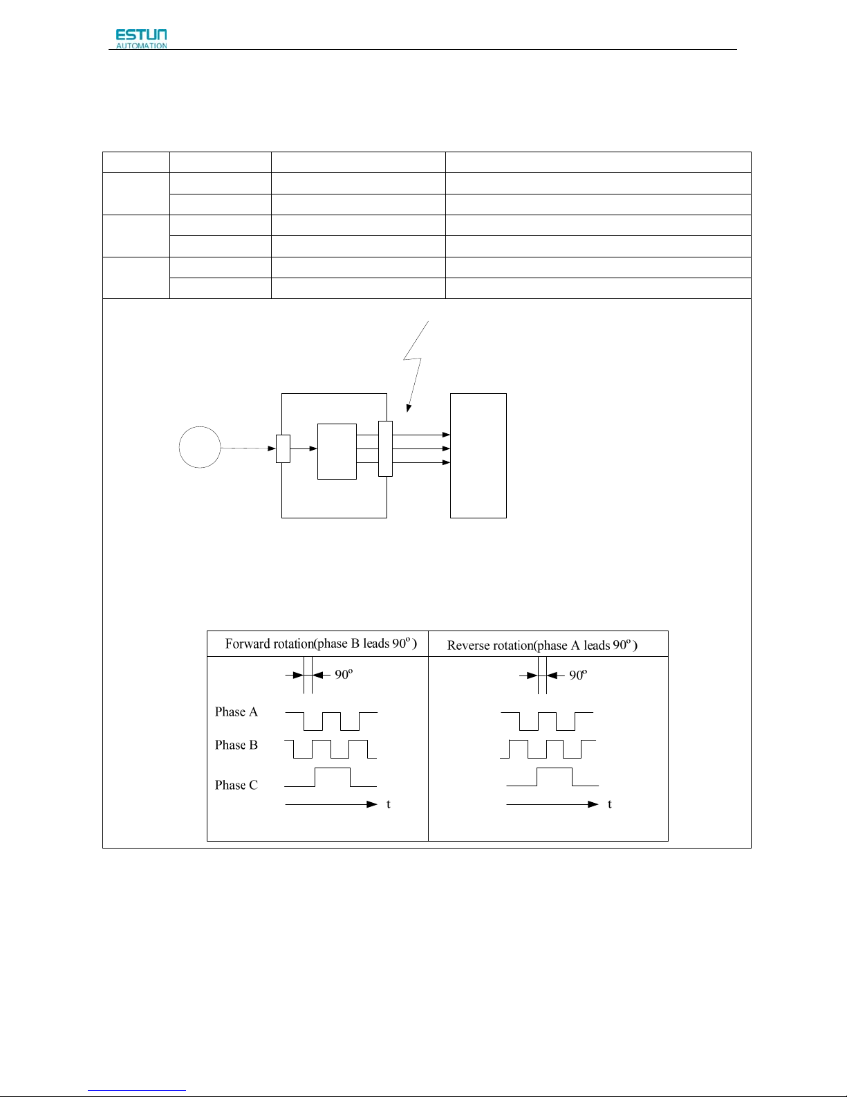
ProNet Series AC Servo User's Manual
- 90 -
4.5.8 Encoder Signal Output
Encoder feedback pulses processed inside the servo drive can be output externally.
Type Signal Name Connector Pin Number Name
Output
PAO CN1-20 Encoder output phase A
/PAO CN1-21 Encoder output phase /A
Output
PBO CN1-22 Encoder output phase B
/PBO CN1-23 Encoder output phase /B
Output
PCO CN1-24 Encoder output phase C(zero-point pulse)
/PCO CN1-25 Encoder output phase /C(zero-point pulse)
Host Controller
PG
Encoder
Serial Data
CN2
Frequency
dividing
circuit
CN1
Phase A(PAO)
Phase B(PBO)
Phase C(PCO)
These outputs explained here.
*
Servodrive
* The dividing output phase form is the same as the standard setting (Pn001.0=0) even if in reverse rotation mode
(Pn001.0=1).
■Output phase form
If the servomotor is not equipped with an absolute encoder, the servomotor needs two full rotations before using the servo
drive's Phase-C pulse output as the zero point reference.
Dividing: Dividing means that the divider converts data into the pulse density (Pn200) based on the pulse data of the
encoder installed on the servomotor, and outputs it. The setting unit is number of pulses/revolution.
Page 93
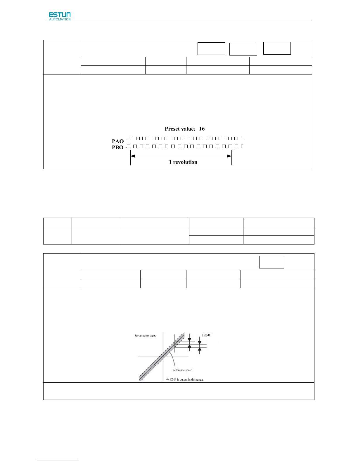
ProNet Series AC Servo User's Manual
- 91 -
Pulse Dividing Ratio Setting
Pn200
PG Dividing Ratio
Setting Range Setting Unit Factory Setting Setting Validation
16~16384 1Puls 16384 After restart
Set the number of pulses for PG output signals (PAO,/PAO,PBO,/PBO) externally from the servo drive.
Feedback pulses from the encoder per revolution are divided inside the servo drive by the number set in Pn200 before
being output. (Set according to the system specifications of the machine or host controller.)
The setting range varies with the number of encoder pulses for the servomotor used.
■Output Example
Pn200=16(when 16 pulses are output per revolution)
4.5.9 Speed coincidence output
The speed coincidence (/V-CMP) output signal is output when the actual servomotor speed during speed control is the
same as the speed reference input. The host controller uses the signal as an interlock.
Type Signal Name Connector Pin Number Setting Meaning
Output /V-CMP(/COIN)
CN1-11,12
(factory setting)
ON(low level) Speed coincides.
OFF(high level) Speed does not coincide.
Pn501
Coincidence Difference
Setting Range Setting Unit Factory Setting Setting Validation
0~100
rpm 10 Immediately
The /V-CMP signal is output when the difference between the speed reference and actual servomotor speed is less than
Pn501.
■Example
The /V-CMP signal turns ON at 1900 to 2100rpm
if the Pn501 parameter is set to 100 and the reference speed is
2000rpm.
■Note
This pin outputs the /COIN signal in position control mode, and the /V-CMP signal in speed control mode.
Speed
Position
Torque
Speed
Page 94
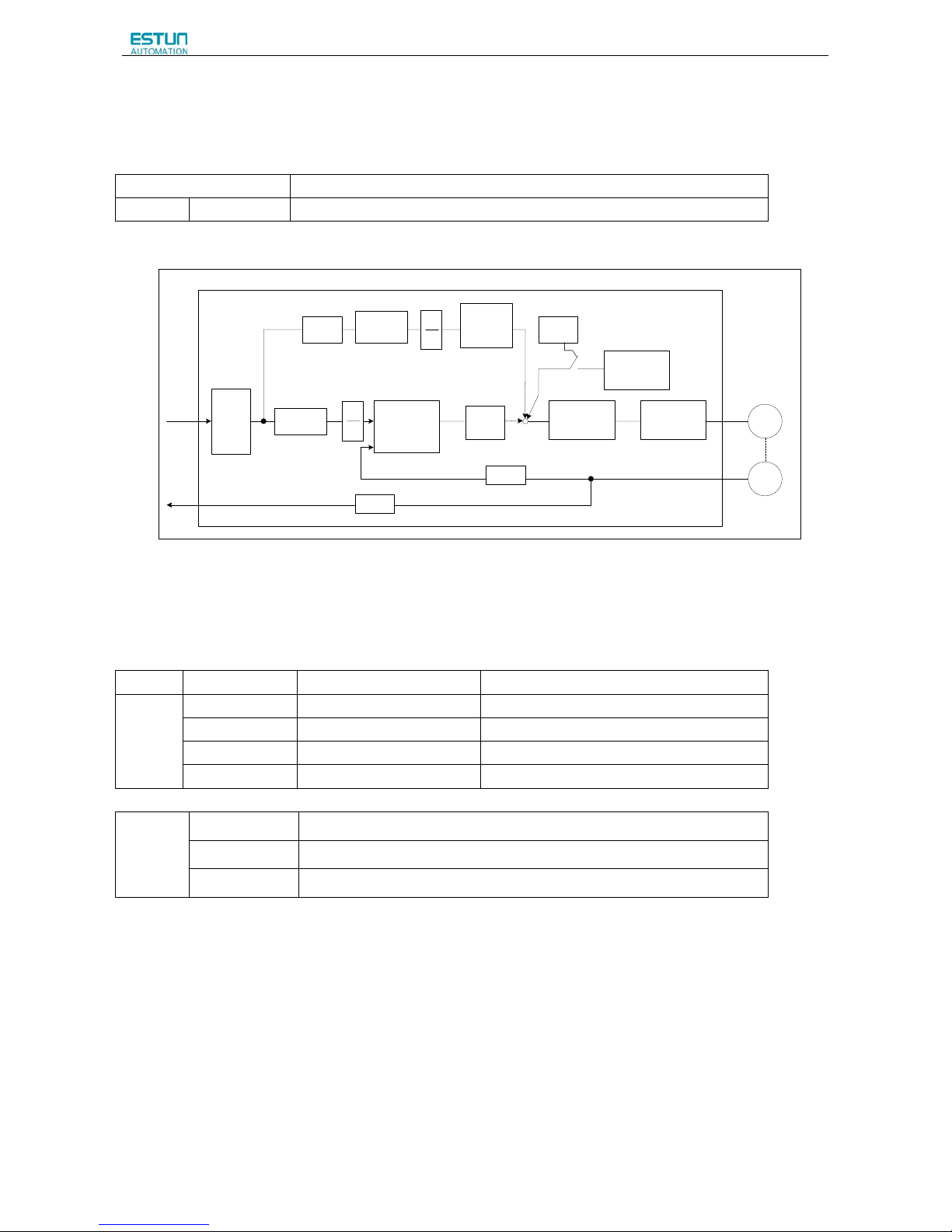
ProNet Series AC Servo User's Manual
- 92 -
4.6 Operating Using Position Control
Set the following parameters for position control using pulse trains.
Parameter Meaning
Pn005
H.□□1□ Control mode selection:position control (pulse train reference)
A block diagram for position control is shown as below.
Differential
Feed forward
B
A
Feed forward
filter time
constant
Offset
Positioning
complete
Current loopSpeed loop
K
P
Error counter
Smoothing
×1
×2
×4
dividing
×4
B
A
Servodrive(in position control)
Pn112 Pn201
Pn202
Pn113
Pn111
Pn500
Pn004.2
Pn204
Pn201
Pn202
Pn200
Reference pulse
PG signal output
Pn104
M
PG
Servomotor
Encoder
-
+
+
+
+
4.6.1 Basic Setting in Position Control
(1)Setting a reference pulse sign
Type Signal Name Connector Pin Number Name
Input
PULS CN1-30 Reference pulse input
/PULS CN1-31 Reference pulse input
SIGN CN1-32 Reference sign input
/SIGN CN1-33 Reference sign input
(2)Setting reference input filter for open collector signal
Pn006 0□□□ when pulse is difference input, servo receiving pulse frequency ≤4M
1□□□ when pulse is difference input, servo receiving pulse frequency ≤650K
2□□□ when pulse is difference input, servo receiving pulse frequency ≤150K
Page 95
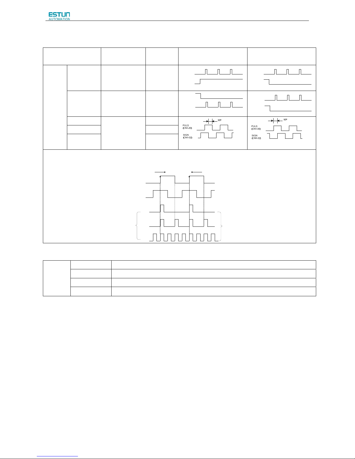
ProNet Series AC Servo User's Manual
- 93 -
(3) Setting a Reference Pulse Form
Set the input form for the servo drive using parameter Pn004.2 according to the host controller specifications.
Parameter
Reference
Pulse Form
Input Pulse
Multiplier
Forward Rotation
Reference
Reverse Rotation
Reverse
Pn004
H.□0□□
Sign+pulse train
(positive logic)
(factory setting)
—
PULS
(CN1-30)
SIGN
(CN1-32)
H
PULS
(CN1-30)
SIGN
(CN1-32)
L
H.□1□□
CW+CCW
(positive logic)
—
PULS
(CN1-30)
SIGN
(CN1-32)
L
PULS
(CN1-30)
SIGN
(CN1-32)
L
H.□2□□
Two-phase pulse
train with 90°
phase differential
(positive logic)
×1
H.□3□□
×2
H.□4□□
×4
■Note:
The input pulse multiplier can be set for the two-phase pulse train with 90° phase differential reference pulse form.
Forward Rotation Reverse Rotation
PULS
(CN1-30)
SIGN
(CN1-32)
Internal processing
×1倍
×2倍
×4倍
Servomotor movement
reference pulses.
(4)Inverse PULS and SIGN reference
Pn004
0□□□
Do not inverse PULS reference and SIGN reference
1□□□
Do not inverse PULS reference; Inverse SIGN reference
2□□□
Inverse PULS reference; Do not inverse SIGN reference
3□□□
Inverse PULS reference and SIGN reference
Page 96

ProNet Series AC Servo User's Manual
- 94 -
(5)Reference Pulse Input Signal Timing
Reference pulse signal form Electrical specifications Remarks
Sign+pulse train input
(SIGN+PULS signal)
Maximum reference frequency:
500kpps (For open-collector output:
200kpps)
t1,t2=0.1µs
t3,t7=0.1µs
t4,t5,t6>3µs
t=1.0µs
(t /T)×10 0 = 50
%
SIGN
PULS
t1
t2
t3
t4
t
T
Forward reference Reverse reference
t5 t6
t7
SIGN
H=forward reference
L=reverse reference
CW pulse+CCW pulse Maximum
reference frequency:500kpps
(For open-collector output:200kpps)
t1
CCW
CW
t2
T
t3
t
Forward reference
Reverse reference
t1,t2=0.1µs
t3>3µs
t=1.0µs
(t /T)×100 = 50%
Two-phase pulse train with 90° phase
differential (phase A +B)
Maximum reference frequency:
×1 input pulse multiplier:500kpps
×2 input pulse multiplier:400kpps
×4 input pulse multiplier:
200kpps
Reverse reference
Phase B lags B by 90º.
Forward reference
Phase B leads A by 90º.
t1
t2
Phase A
Phase B
T
t
t1,t2=0.1µs
t=1 .0µs
(t /T)× 100 = 50%
A parameter
Pn004.2 can be
used to switch of
the input pulse
multiplier mode.
(6)Connection Example
The pulse train output form from the host controller corresponds to the following:
• Line-driver Output
• +24V Open-collector output
• +12V/+5V Open-collector output
(a)Connection Example for Line-driver Output
Applicable line driver: SN75174 manufactured by TI or MC3487 or the equivalent.
Host controller
Line-driver
*
Servodrive
Photocoupler
PULS
/PULS
30
31
150Ω
CN1
SIGN
/SIGN
32
33
150Ω
*
Represents twisted-pair wires。
Page 97

ProNet Series AC Servo User's Manual
- 95 -
(b)Connection Example for Open-Collector Gate Output
NPN OC GATE OUTPUT
VDC
R
/SIGN
GND
75Ω
2KΩ
75Ω
1CN-30
1CN-31
1CN-34
1CN-32
1CN-33
2KΩ
R
SIGN
/PULS
PULS
NOTE:
VDC=12~24V
R=(VDC-1.5Volt)/10mA-150
VDC=12V,
R=1KΩ/0.25W
VDC=24V,
R=2KΩ/0.25W
75Ω
75Ω
Host controller
Servodrive
PNP OC GATE OUTPUT
VDC
R
/SIGN
GND
75Ω
2KΩ
75Ω
1CN-30
1CN-31
1CN-34
1CN-32
1CN-33
2KΩ
R
SIGN
/PULS
PULS
NOTE:
VDC=12~24V
R=(VDC-1.5Volt)/10mA-150
VDC=12V,
R=1KΩ/0.25W
VDC=24V,
R=2KΩ/0.25W
75Ω
75Ω
Servodrive
Host controller
Note:When the host controller is applied by open-collector signal output, the input signal noise margin lowers. When a
position error caused by the noise occurs, set the parameter Pn006.3.
Page 98
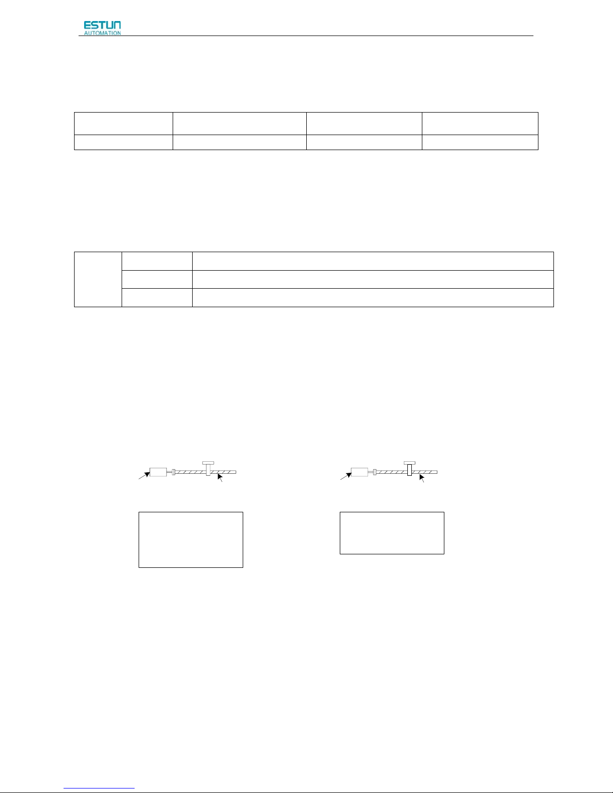
ProNet Series AC Servo User's Manual
- 96 -
4.6.2 Setting the Clear Signal
(1)Setting the Clear Signal
Type Sign Name Connector Pin Numbe Function
Input /CLR 1CN-40 error counter clear
When the /CLR signal is set to low level, clear error counter:
·The error counter inside the servo drive is set to “0”
·Position loop operation is disabled.
(2)Setting the Clear Signal Mode
In position control mode, pulses will be still presented in the servo drive when servo OFF, thus it should be cleared when
servo drive is turned ON. Setting Pn004 to choose whether clearing the pulses automatically when servo OFF.
Pn004
□□0□
Clear the error pulse when S-OFF, do not when overtravel.
□□1□ Do not clear the error pulse.
□□2□
Clear the error pulse when S-OFF or overtravel (excep for zero clamp)
4.6.3 Setting the Electronic Gear
(1)Electronic Gear
The electronic gear enables the workpiece travel distance per input reference pulse from the host controller to be set to
any value.
One reference pulse from the host controller, i.e., the minimum position data unit, is called a reference unit.
When the Electronic Gear is Not Used When the Electronic Gear is Used
workpiece
workpiece
No. of encoder
pulses:32768
Ball screw pitch:6mm
No. of encoder
pulses:32768
Ball screw pitch:6mm
One revolution is 6mm. Therefore 10÷6=
1.6666 revolutions.
32768×4 pulses is one revolution.
Therefore, 1.6666×32768×4=218445
pulses. 218445 pulses are input as
reference pulses.
The equation must be calculated at the
host controller.
To move a workpiece 10mm :
The reference unit is 1µm. Therefore, to
move the workpiece 10mm (10000µm),
1pulse=1µm, so 10000/1=10000 pulses.
Input 10000 pulses per 10mm of
workpiece movement.
To move a workpiece 10mm using
reference units:
Reference unit:1µm
Page 99
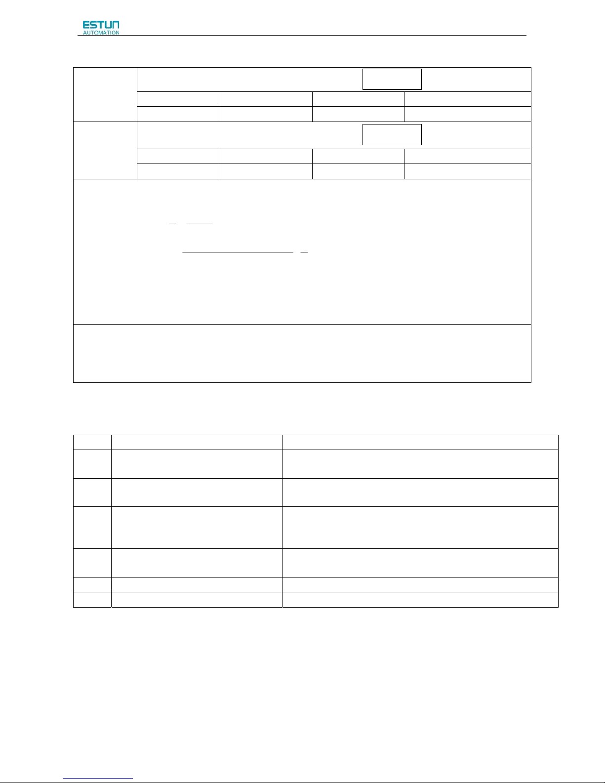
ProNet Series AC Servo User's Manual
- 97 -
(2)Related Parameters
Pn201
Electronic Gear Ratio (Numerator)
Setting Range Setting Unit Factory Setting Setting Validation
1~65535
— 1 After restart
Pn202
Electronic Gear Ratio (Denominator)
Setting Range Setting Unit Factory Setting Setting Validation
1~65535
— 1 After restart
The deceleration ratio of the servomotor and the load shaft is given as n/m where m is the
rotation of the servomotor and n is the rotation of the load shaft.
Electronic gear ratio:
202
201
Pn
Pn
A
B
=
n
m
unitsreferencerevolutionshaft
loadpercedisTravel
pulsesencoderofNo
×
×
=
)(
tan
4.
·If the ratio is outside the setting range, reduce the fraction (both numerator and denominator) until you obtain integers
within the range.
·Be careful not to change the electronic gear ratio (B/A).
■Important
·Electronic gear ratio setting range: 0.01≤electronic gear ratio(B/A)≤ 100
·If the electronic gear ratio is outside this range, the servo drive will not operate properly. In this case, modify the load
configuration or reference unit.
(3)Procedure for Setting the Electronic Gear Ratio
Use the following procedure to set the electronic gear ratio.
Step Operation Description
1
Check machine specifications.
Check the deceleration ratio, ball screw pitch and pulley
diameter.
2
Check the number of encoder
pulses.
Check the number of encoder pulses for the servomotor used.
3
Determine the reference unit used.
Determine the reference unit from the host controller,
considering the machine specifications and positioning
accuracy.
4
Calculate the travel distance per load shaft
revolution.
Calculate the number of reference units necessary to turn the load shaft
one revolution based on the previously determined reference units.s
5
Calculate the electronic gear ratio. Use the electronic gear ratio equation to calculate the ratio (B/A).
6
Set parameters. Set parameters using the calculated values.
Position
Position
Page 100
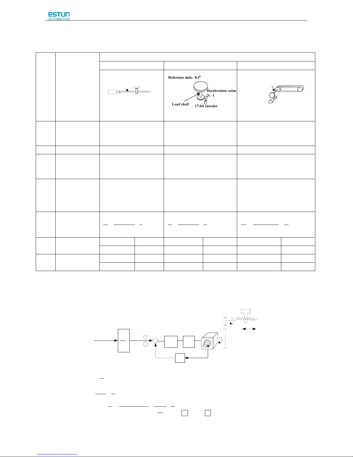
ProNet Series AC Servo User's Manual
- 98 -
(4)Electronic Gear Ratio Setting Examples
The following examples show electronic gear ratio settings for different load configurations.
Step Operation
Load Configuration
Ball Screw Disc Table Belt and Pulley
17-bit encoder
Ball screw pitch:6mm
Reference unit:0.001mm
Load shaft
Reference unit:0.01mm
Load shaft
Deceleration ratio:
2:1
17-bit encoder
Pulley diameter:
F 100mm
1
Check machine
specifications.
Ball screw pitch:mm
Deceleration ratio:1/1
Rotation angle per revolution
:360° Deceleration ratio:3/1
Pulley diameter:100 mm
(pulley circumference:314 mm)
·Deceleration ratio:2/1
2 Encoder 17-bit:32768P/R 17-bit:32768P/R 17-bit:32768P/R
3
Determine the
reference unit
used
1 reference unit:
0.001mm(1μm)
1 reference unit:0.1° 1 reference unit:0.01mm
4
Calculate the
travel distance
per load shaft
revolution
6mm/0.001mm=6000 360°/0.1°=3600 314mm/0.01mm=31400
5
Calculate the
electronic gear
ratio
1
1
6000
432768××
=
A
B
1
3
3600
432768
×
×
=
A
B
1
2
31400
432768××
=
A
B
6
Set parameters
Pn201 131072 Pn201 393216 Pn201 262144
Pn202 6000 Pn202 3600 Pn202 31400
7
Final Result
Pn201 32768 Pn201 32768 Pn201 32768
Pn202 1500 Pn202 300 Pn202 3925
·Reduce the fraction (both numerator and denominator) if the calculated result will not be within the setting range.
·For example, reduce the above numerators and denominators by four or other numbers to obtain the final results in step
7 and complete the settings.
(5)Electronic Gear Ratio Equation
:Deceleration ratio
Reference pulse
)/( PmmlΔ
B
A
+
—
Speed
loop
×4
n
Pitch=P(mm/rev
)
m
Servomotor
P
G(P/rev))
:)/( PmmlΔ
Reference unit
Encoder pulses
P(mm/rev):Ball screw pitch
n
m
mP
A
Bpn
G ××=×
Δ
×
4)(
l
n
m
P
P
pn
mP
A
B
GG
×
Δ
×
=
×
Δ×××
=
l
l 44
)(
Set A and B with the following param eters:
A B
:Pn202 :Pn201
P
G(P/rev)):
Position
loop
 Loading...