

Estun PRONET-10AMA, EMG-20ADA22 User Manual
ProNet series AC servo system user’s manual V.1.08
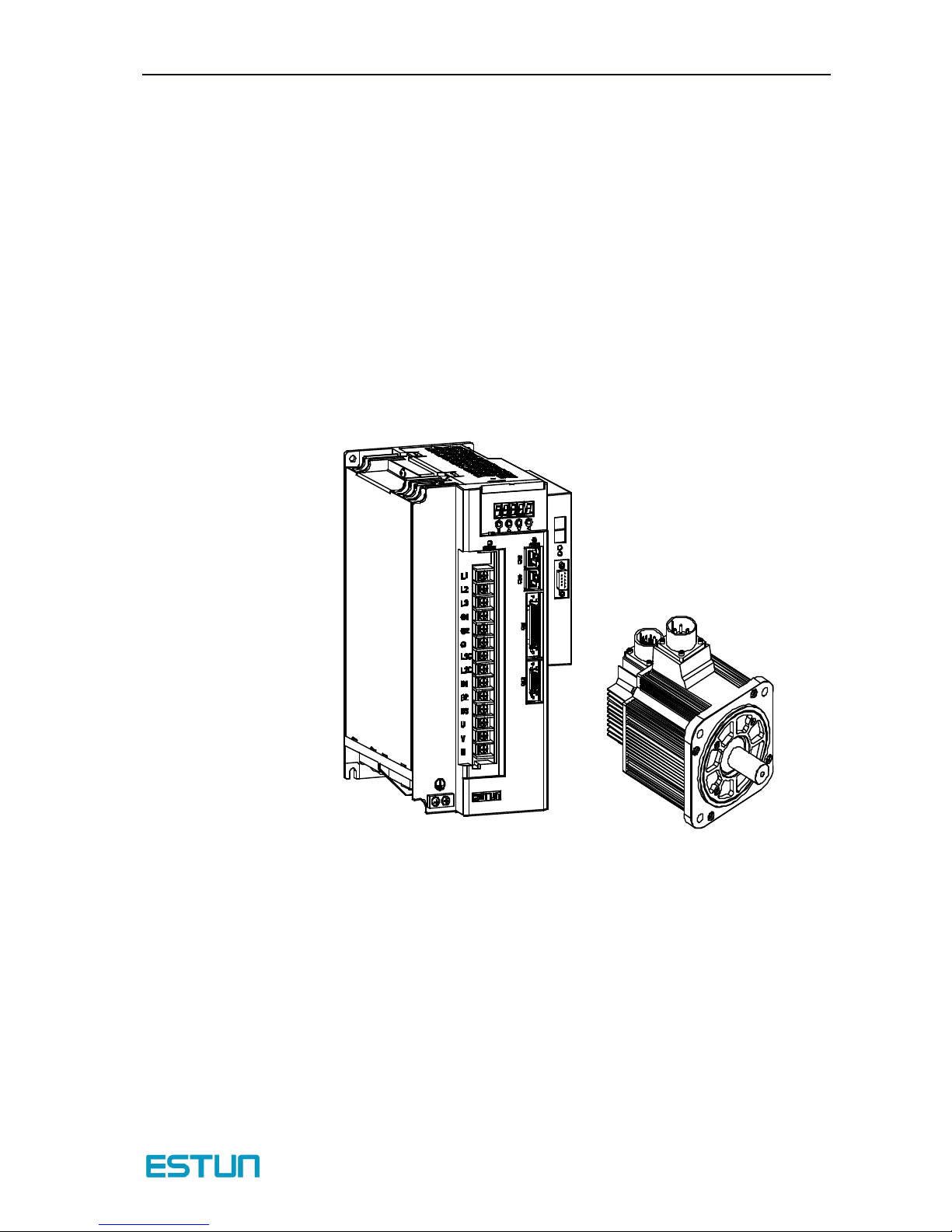
ProNet
ProNet
ProNet
ProNet series
series
series
series AC
AC
AC
AC servo
servo
servo
servo system
system
system
system
User’s Manual
V.
1.08
Estun Limited Warranty
This manual does not entitle you to any rights. Estun reserves the right to change this
manual without prior notice. All rights reserved. The copyright is held by Estun. No part
of this publication may be copied or reproduced without written permission fr om Estun.

Contents
- 1 -
About this manual
This manual describes the following information required for designing and maintaining ProNet
series servodrives.
• Specification of the servodrives and servomotors.
• Procedures for installing the servodrives and servomotors.
• Procedures for wiring the servodrives and servomotors.
• Procedures for operation of the servodrives.
• Procedures for using the panel operator.
• Communication protocols.
• Ratings and characteristics.
Intended Audience:
• Those designing ProNet series servodrive systems.
• Those installing or wiring ProNet series servodrives.
• Those performing trial operation or adjustments of ProNet series servodrives.
• Those maintaining or inspecting ProNet series servodrives.

ProNet series AC servo system User’s manual V.1.08
- 2 -
Safety Precaution s
■
Do not connect the servomotor directly to the local electrical network.
Failure to observe this may result in damage to servomotor.
■
Do not plug or unplug connectors from servodrive after power is on.
Failure to observe this may result in damage to servodrive and servomotor.
■
Note that residual voltage
still
remains in the servodrive even after the power is turned off.
Please be noted that even after the power is turned off, residual voltage
still
remains in the capacitor
inside the servodrive. I f inspection is to be performed after the power is turned off, always wait at least
5 minutes to avoid the risk of an electrical shock.
■
Keep servodrives and other devices separated by at least 10mm.
The servodrive generates heat. Install the servodrive so that it can radiate heat freely. When installing
servodrives with other devices in a control panel, provide at least 10mm space between them and
50mm space above and below them.Please install servodrives in an environment free from
condensation, vibration and shock.
■
Perform noise reduction and grounding properly.
Please comply w ith the following instructions strictly to avoid the noisy generated by signal lines.
1. Separate high-voltage cables from low-voltage cables.
2. Use cables as short as possible.
3. Sigle point grounding is required for the servomotor and servodrive (grounding resistance 100 Ω or
below).
4. Never use a line filter for the power supply in the circuit.
■
Conduct a voltage resistance test for the servodrive under the following conditions:
1. Input voltage: AC 1500Vrms, 1 minute
2. Braking current: 100mA
3. Frequency:50/60Hz
4. Voltage applied point: Between L1, L2,L3 terminals and frame ground.
■
Use a fast-response type ground-fault interrupter.
For a ground-fault interrupter, always use a fast-response type or one designed for PWM inverters. Do
not use a time-delay type.
■
Do not make any extreme adjustments or setting changes of parameters.
Failure to observe this caution may result in injury or damage to the product due to unstable operation .
■
The servomotor cannot be operated by turning the power on and off.
Frequently turning the power ON and OFF causes the internal circuit elements to deteriorate, resulting
in unexpected problems.Alw ays start or stop the servomotor by using reference pulses.

Contents
- 3 -
Contents
ProNet series AC servo system
. . . . . . . . . . . . . . . . . . . . . . . . . . . . . . . . . . . . . . . . . . . . . . . . . . . . . . . . . . . . . . . . . . . . . . . . . . . . . . . . . . . . . . . . .
-
1
-
About this manual
. . . . . . . . . . . . . . . . . . . . . . . . . . . . . . . . . . . . . . . . . . . . . . . . . . . . . . . . . . . . . . . . . . . . . . . . . . . . . . . . . . . . . . . . . . . . . . . . . . . . . . . . . . . . . .
-
1
-
Safety Precautions
. . . . . . . . . . . . . . . . . . . . . . . . . . . . . . . . . . . . . . . . . . . . . . . . . . . . . . . . . . . . . . . . . . . . . . . . . . . . . . . . . . . . . . . . . . . . . . . . . . . . . . . . . . . .
-
2
-
Contents
. . . . . . . . . . . . . . . . . . . . . . . . . . . . . . . . . . . . . . . . . . . . . . . . . . . . . . . . . . . . . . . . . . . . . . . . . . . . . . . . . . . . . . . . . . . . . . . . . . . . . . . . . . . . . . . . . . . . . . . . . . . .
-3-
Chapter 1
. . . . . . . . . . . . . . . . . . . . . . . . . . . . . . . . . . . . . . . . . . . . . . . . . . . . . . . . . . . . . . . . . . . . . . . . . . . . . . . . . . . . . . . . . . . . . . . . . . . . . . . . . . . . . . . . . . . . . . . . . . .
-
7
-
Checking Products and Parts Names
. . . . . . . . . . . . . . . . . . . . . . . . . . . . . . . . . . . . . . . . . . . . . . . . . . . . . . . . . . . . . . . . . . . . . . . . . . . . . . .
-
7
-
1.1 Checking Products on Delivery . . . . . . . . . . . . . . . . . . . . . . . . . . . . . . . . . . . . . . . . . . . . . . . . . . . . . . . . . . . . . . . . . . . . . . . . . . . . . . . . . . . . . . . . . . . . . . . . - 7 -
1.1.1 Servomotor . . . . . . . . . . . . . . . . . . . . . . . . . . . . . . . . . . . . . . . . . . . . . . . . . . . . . . . . . . . . . . . . . . . . . . . . . . . . . . . . . . . . . . . . . . . . . . . . . . . . . . . . . . . . . . . . . . . . . - 7 -
1.1.2 Servodrive . . . . . . . . . . . . . . . . . . . . . . . . . . . . . . . . . . . . . . . . . . . . . . . . . . . . . . . . . . . . . . . . . . . . . . . . . . . . . . . . . . . . . . . . . . . . . . . . . . . . . . . . . . . . . . . . . . . . . . - 9 -
1.2 Product Part N ames . . . . . . . . . . . . . . . . . . . . . . . . . . . . . . . . . . . . . . . . . . . . . . . . . . . . . . . . . . . . . . . . . . . . . . . . . . . . . . . . . . . . . . . . . . . . . . . . . . . . . . . . . . . . . . . . - 11 -
1.2.1 Servomotor . . . . . . . . . . . . . . . . . . . . . . . . . . . . . . . . . . . . . . . . . . . . . . . . . . . . . . . . . . . . . . . . . . . . . . . . . . . . . . . . . . . . . . . . . . . . . . . . . . . . . . . . . . . . . . . . . . . - 11 -
1.2.2 Servodrive . . . . . . . . . . . . . . . . . . . . . . . . . . . . . . . . . . . . . . . . . . . . . . . . . . . . . . . . . . . . . . . . . . . . . . . . . . . . . . . . . . . . . . . . . . . . . . . . . . . . . . . . . . . . . . . . . . . . - 12 -
Chapter 2
. . . . . . . . . . . . . . . . . . . . . . . . . . . . . . . . . . . . . . . . . . . . . . . . . . . . . . . . . . . . . . . . . . . . . . . . . . . . . . . . . . . . . . . . . . . . . . . . . . . . . . . . . . . . . . . . . . . . . . . . .
-
15
-
Installation
. . . . . . . . . . . . . . . . . . . . . . . . . . . . . . . . . . . . . . . . . . . . . . . . . . . . . . . . . . . . . . . . . . . . . . . . . . . . . . . . . . . . . . . . . . . . . . . . . . . . . . . . . . . . . . . . . . . . . . . .
-
15
-
2.1 Servomotor . . . . . . . . . . . . . . . . . . . . . . . . . . . . . . . . . . . . . . . . . . . . . . . . . . . . . . . . . . . . . . . . . . . . . . . . . . . . . . . . . . . . . . . . . . . . . . . . . . . . . . . . . . . . . . . . . . . . . . . . . . . . . - 15 -
2.1.1 Storage . . . . . . . . . . . . . . . . . . . . . . . . . . . . . . . . . . . . . . . . . . . . . . . . . . . . . . . . . . . . . . . . . . . . . . . . . . . . . . . . . . . . . . . . . . . . . . . . . . . . . . . . . . . . . . . . . . . . . . . . . - 15 -
2.1.2 I nstallation Sites . . . . . . . . . . . . . . . . . . . . . . . . . . . . . . . . . . . . . . . . . . . . . . . . . . . . . . . . . . . . . . . . . . . . . . . . . . . . . . . . . . . . . . . . . . . . . . . . . . . . . . . . . . . - 15 -
2.1.3 I nstallation Alignment . . . . . . . . . . . . . . . . . . . . . . . . . . . . . . . . . . . . . . . . . . . . . . . . . . . . . . . . . . . . . . . . . . . . . . . . . . . . . . . . . . . . . . . . . . . . . . . . . . . - 16 -
2.1.4 I nstallation Orientation . . . . . . . . . . . . . . . . . . . . . . . . . . . . . . . . . . . . . . . . . . . . . . . . . . . . . . . . . . . . . . . . . . . . . . . . . . . . . . . . . . . . . . . . . . . . . . . . . . - 16 -
2.1.5 H andling
Oil
and Water . . . . . . . . . . . . . . . . . . . . . . . . . . . . . . . . . . . . . . . . . . . . . . . . . . . . . . . . . . . . . . . . . . . . . . . . . . . . . . . . . . . . . . . . . . . . . . . . . - 16 -
2.1.6 Cable Tension . . . . . . . . . . . . . . . . . . . . . . . . . . . . . . . . . . . . . . . . . . . . . . . . . . . . . . . . . . . . . . . . . . . . . . . . . . . . . . . . . . . . . . . . . . . . . . . . . . . . . . . . . . . . . . . - 17 -
2.2 Servodrive . . . . . . . . . . . . . . . . . . . . . . . . . . . . . . . . . . . . . . . . . . . . . . . . . . . . . . . . . . . . . . . . . . . . . . . . . . . . . . . . . . . . . . . . . . . . . . . . . . . . . . . . . . . . . . . . . . . . . . . . . . . . . . - 17 -
2.2.1 Storage . . . . . . . . . . . . . . . . . . . . . . . . . . . . . . . . . . . . . . . . . . . . . . . . . . . . . . . . . . . . . . . . . . . . . . . . . . . . . . . . . . . . . . . . . . . . . . . . . . . . . . . . . . . . . . . . . . . . . . . . . - 17 -
2.2.2 I nstallation Sites . . . . . . . . . . . . . . . . . . . . . . . . . . . . . . . . . . . . . . . . . . . . . . . . . . . . . . . . . . . . . . . . . . . . . . . . . . . . . . . . . . . . . . . . . . . . . . . . . . . . . . . . . . . - 17 -
2.2.3 I nstallation Orientation . . . . . . . . . . . . . . . . . . . . . . . . . . . . . . . . . . . . . . . . . . . . . . . . . . . . . . . . . . . . . . . . . . . . . . . . . . . . . . . . . . . . . . . . . . . . . . . . . . - 18 -
2.2.4 I nstallation Method . . . . . . . . . . . . . . . . . . . . . . . . . . . . . . . . . . . . . . . . . . . . . . . . . . . . . . . . . . . . . . . . . . . . . . . . . . . . . . . . . . . . . . . . . . . . . . . . . . . . . . . - 18 -
Chapter 3
. . . . . . . . . . . . . . . . . . . . . . . . . . . . . . . . . . . . . . . . . . . . . . . . . . . . . . . . . . . . . . . . . . . . . . . . . . . . . . . . . . . . . . . . . . . . . . . . . . . . . . . . . . . . . . . . . . . . . . . . .
-
20
-
Wiring
. . . . . . . . . . . . . . . . . . . . . . . . . . . . . . . . . . . . . . . . . . . . . . . . . . . . . . . . . . . . . . . . . . . . . . . . . . . . . . . . . . . . . . . . . . . . . . . . . . . . . . . . . . . . . . . . . . . . . . . . . . . . . . .
-
20
-
3.1 Main Circuit Wiring . . . . . . . . . . . . . . . . . . . . . . . . . . . . . . . . . . . . . . . . . . . . . . . . . . . . . . . . . . . . . . . . . . . . . . . . . . . . . . . . . . . . . . . . . . . . . . . . . . . . . . . . . . . . . . . . . - 20 -
3.1.1 N ames and Functions of Main Circuit Terminals . . . . . . . . . . . . . . . . . . . . . . . . . . . . . . . . . . . . . . . . . . . . . . . . . . . . . . . . . . - 20 -
3.1.2 Typical Main Circuit Wiring Examples . . . . . . . . . . . . . . . . . . . . . . . . . . . . . . . . . . . . . . . . . . . . . . . . . . . . . . . . . . . . . . . . . . . . . . . . . . - 21 -
3.2 I/O Signals . . . . . . . . . . . . . . . . . . . . . . . . . . . . . . . . . . . . . . . . . . . . . . . . . . . . . . . . . . . . . . . . . . . . . . . . . . . . . . . . . . . . . . . . . . . . . . . . . . . . . . . . . . . . . . . . . . . . . . . . . . . . . . - 23 -
3.2.1 Examples of I/O Signal Connections . . . . . . . . . . . . . . . . . . . . . . . . . . . . . . . . . . . . . . . . . . . . . . . . . . . . . . . . . . . . . . . . . . . . . . . . . . . . - 23 -
3.2.2 I /O Signal Names and Functions . . . . . . . . . . . . . . . . . . . . . . . . . . . . . . . . . . . . . . . . . . . . . . . . . . . . . . . . . . . . . . . . . . . . . . . . . . . . . . . . . . - 24 -
3.2.3 I /O Signal Connector (CN1) Terminal Layout . . . . . . . . . . . . . . . . . . . . . . . . . . . . . . . . . . . . . . . . . . . . . . . . . . . . . . . . . . . . . . - 26 -
3.2.4 I nterface Circuit . . . . . . . . . . . . . . . . . . . . . . . . . . . . . . . . . . . . . . . . . . . . . . . . . . . . . . . . . . . . . . . . . . . . . . . . . . . . . . . . . . . . . . . . . . . . . . . . . . . . . . . . . . . . - 27 -
3.3 Wiring Encoders . . . . . . . . . . . . . . . . . . . . . . . . . . . . . . . . . . . . . . . . . . . . . . . . . . . . . . . . . . . . . . . . . . . . . . . . . . . . . . . . . . . . . . . . . . . . . . . . . . . . . . . . . . . . . . . . . . . . . - 28 -
3.3.1 Connecting an Encoder(CN2) . . . . . . . . . . . . . . . . . . . . . . . . . . . . . . . . . . . . . . . . . . . . . . . . . . . . . . . . . . . . . . . . . . . . . . . . . . . . . . . . . . . . . . - 28 -
3.3.2 Encoder Connector(CN2) Terminal Layout . . . . . . . . . . . . . . . . . . . . . . . . . . . . . . . . . . . . . . . . . . . . . . . . . . . . . . . . . . . . . . . . . . - 29 -

ProNet series AC servo system User’s manual V.1.08
- 4 -
3.4 Communication Connection . . . . . . . . . . . . . . . . . . . . . . . . . . . . . . . . . . . . . . . . . . . . . . . . . . . . . . . . . . . . . . . . . . . . . . . . . . . . . . . . . . . . . . . . . . . . . . . . . . . - 30 -
3.4.1 Communication Connector(CN3) Terminal Layout . . . . . . . . . . . . . . . . . . . . . . . . . . . . . . . . . . . . . . . . . . . . . . . . . . . . . . - 30 -
3.4.2 Communication Connector(CN4) Terminal Layout . . . . . . . . . . . . . . . . . . . . . . . . . . . . . . . . . . . . . . . . . . . . . . . . . . . . . . - 30 -
3.5 Standard Wiring Ex amples . . . . . . . . . . . . . . . . . . . . . . . . . . . . . . . . . . . . . . . . . . . . . . . . . . . . . . . . . . . . . . . . . . . . . . . . . . . . . . . . . . . . . . . . . . . . . . . . . . . . . - 31 -
3.5.1 Three-phase 200V(ProNet-02A ~ 04A) . . . . . . . . . . . . . . . . . . . . . . . . . . . . . . . . . . . . . . . . . . . . . . . . . . . . . . . . . . . . . . . . . . . . . . . . - 31 -
3.5.2 Three-phase 200V(ProNet-08A ~ 50A) . . . . . . . . . . . . . . . . . . . . . . . . . . . . . . . . . . . . . . . . . . . . . . . . . . . . . . . . . . . . . . . . . . . . . . . . - 32 -
3.5.3 Three-phase 400V(ProNet-75D ~ 1ED) . . . . . . . . . . . . . . . . . . . . . . . . . . . . . . . . . . . . . . . . . . . . . . . . . . . . . . . . . . . . . . . . . . . . . . . . - 33 -
3.5.4 Position Control Mode . . . . . . . . . . . . . . . . . . . . . . . . . . . . . . . . . . . . . . . . . . . . . . . . . . . . . . . . . . . . . . . . . . . . . . . . . . . . . . . . . . . . . . . . . . . . . . . . . . - 34 -
3.5.5 Speed Control Mode . . . . . . . . . . . . . . . . . . . . . . . . . . . . . . . . . . . . . . . . . . . . . . . . . . . . . . . . . . . . . . . . . . . . . . . . . . . . . . . . . . . . . . . . . . . . . . . . . . . . . - 35 -
3.5.6 Torque Control Mode . . . . . . . . . . . . . . . . . . . . . . . . . . . . . . . . . . . . . . . . . . . . . . . . . . . . . . . . . . . . . . . . . . . . . . . . . . . . . . . . . . . . . . . . . . . . . . . . . . . . - 36 -
Chapter 4
. . . . . . . . . . . . . . . . . . . . . . . . . . . . . . . . . . . . . . . . . . . . . . . . . . . . . . . . . . . . . . . . . . . . . . . . . . . . . . . . . . . . . . . . . . . . . . . . . . . . . . . . . . . . . . . . . . . . . . . . .
-
37
-
Operation
. . . . . . . . . . . . . . . . . . . . . . . . . . . . . . . . . . . . . . . . . . . . . . . . . . . . . . . . . . . . . . . . . . . . . . . . . . . . . . . . . . . . . . . . . . . . . . . . . . . . . . . . . . . . . . . . . . . . . . . . .
-
37
-
4.1 Trial Operation . . . . . . . . . . . . . . . . . . . . . . . . . . . . . . . . . . . . . . . . . . . . . . . . . . . . . . . . . . . . . . . . . . . . . . . . . . . . . . . . . . . . . . . . . . . . . . . . . . . . . . . . . . . . . . . . . . . . . . . . - 37 -
4.1.1 Trial Operation for Servomotor Without Load . . . . . . . . . . . . . . . . . . . . . . . . . . . . . . . . . . . . . . . . . . . . . . . . . . . . . . . . . . . . . . . - 39 -
4.1.2 Trial Operation for Servomotor w ithout Load from Host Reference . . . . . . . . . . . . . . . . . . . . . . . . . . . . . - 42 -
4.1.3 Trial Operation with the Servomotor Connected to the Machine . . . . . . . . . . . . . . . . . . . . . . . . . . . . . . . . . . - 46 -
4.1.4 Trial Operation for Servomotor w ith Brakes . . . . . . . . . . . . . . . . . . . . . . . . . . . . . . . . . . . . . . . . . . . . . . . . . . . . . . . . . . . . . . . . . - 47 -
4.1.5 Position Control by H ost Controller . . . . . . . . . . . . . . . . . . . . . . . . . . . . . . . . . . . . . . . . . . . . . . . . . . . . . . . . . . . . . . . . . . . . . . . . . . . . . . - 47 -
4.2 Control Mode Selection . . . . . . . . . . . . . . . . . . . . . . . . . . . . . . . . . . . . . . . . . . . . . . . . . . . . . . . . . . . . . . . . . . . . . . . . . . . . . . . . . . . . . . . . . . . . . . . . . . . . . . . . . . - 48 -
4.3 Setting Common Basic Functions . . . . . . . . . . . . . . . . . . . . . . . . . . . . . . . . . . . . . . . . . . . . . . . . . . . . . . . . . . . . . . . . . . . . . . . . . . . . . . . . . . . . . . . . . . - 49 -
4.3.1 Setting the Servo ON Signal . . . . . . . . . . . . . . . . . . . . . . . . . . . . . . . . . . . . . . . . . . . . . . . . . . . . . . . . . . . . . . . . . . . . . . . . . . . . . . . . . . . . . . . . - 49 -
4.3.2 Switching the Servomotor Rotation Direction . . . . . . . . . . . . . . . . . . . . . . . . . . . . . . . . . . . . . . . . . . . . . . . . . . . . . . . . . . . . . . . - 50 -
4.3.3 Setting the Overtravel Limit Function . . . . . . . . . . . . . . . . . . . . . . . . . . . . . . . . . . . . . . . . . . . . . . . . . . . . . . . . . . . . . . . . . . . . . . . . . . . - 51 -
4.3.4 Setting for Holding Brakes . . . . . . . . . . . . . . . . . . . . . . . . . . . . . . . . . . . . . . . . . . . . . . . . . . . . . . . . . . . . . . . . . . . . . . . . . . . . . . . . . . . . . . . . . . . - 54 -
4.3.5 I nstantaneous Power Loss Settings . . . . . . . . . . . . . . . . . . . . . . . . . . . . . . . . . . . . . . . . . . . . . . . . . . . . . . . . . . . . . . . . . . . . . . . . . . . . . - 56 -
4.4 Absolute Encoders . . . . . . . . . . . . . . . . . . . . . . . . . . . . . . . . . . . . . . . . . . . . . . . . . . . . . . . . . . . . . . . . . . . . . . . . . . . . . . . . . . . . . . . . . . . . . . . . . . . . . . . . . . . . . . . . . . - 57 -
4.4.1 Selecting an Absolute Encoder . . . . . . . . . . . . . . . . . . . . . . . . . . . . . . . . . . . . . . . . . . . . . . . . . . . . . . . . . . . . . . . . . . . . . . . . . . . . . . . . . . . . - 57 -
4.4.2 H andling Battery . . . . . . . . . . . . . . . . . . . . . . . . . . . . . . . . . . . . . . . . . . . . . . . . . . . . . . . . . . . . . . . . . . . . . . . . . . . . . . . . . . . . . . . . . . . . . . . . . . . . . . . . . . . - 58 -
4.4.3 Replacing Battery . . . . . . . . . . . . . . . . . . . . . . . . . . . . . . . . . . . . . . . . . . . . . . . . . . . . . . . . . . . . . . . . . . . . . . . . . . . . . . . . . . . . . . . . . . . . . . . . . . . . . . . . . - 59 -
4.4.4 Absolute Encoder Setup(Fn010 、 Fn011) . . . . . . . . . . . . . . . . . . . . . . . . . . . . . . . . . . . . . . . . . . . . . . . . . . . . . . . . . . . . . . . . . . . . . - 59 -
4.5 Operating Using Speed Control with Analog Reference . . . . . . . . . . . . . . . . . . . . . . . . . . . . . . . . . . . . . . . . . . . . . . . . . . . . . . . . . - 60 -
4.5.1 Setting Parameters . . . . . . . . . . . . . . . . . . . . . . . . . . . . . . . . . . . . . . . . . . . . . . . . . . . . . . . . . . . . . . . . . . . . . . . . . . . . . . . . . . . . . . . . . . . . . . . . . . . . . . . - 60 -
4.5.2 Setting I nput Signals . . . . . . . . . . . . . . . . . . . . . . . . . . . . . . . . . . . . . . . . . . . . . . . . . . . . . . . . . . . . . . . . . . . . . . . . . . . . . . . . . . . . . . . . . . . . . . . . . . . . . - 61 -
4.5.3 Adjusting Reference Offset . . . . . . . . . . . . . . . . . . . . . . . . . . . . . . . . . . . . . . . . . . . . . . . . . . . . . . . . . . . . . . . . . . . . . . . . . . . . . . . . . . . . . . . . . . . - 61 -
4.5.4 Soft Start . . . . . . . . . . . . . . . . . . . . . . . . . . . . . . . . . . . . . . . . . . . . . . . . . . . . . . . . . . . . . . . . . . . . . . . . . . . . . . . . . . . . . . . . . . . . . . . . . . . . . . . . . . . . . . . . . . . . . . . - 64 -
4.5.5 Speed Reference Filter Time Constant . . . . . . . . . . . . . . . . . . . . . . . . . . . . . . . . . . . . . . . . . . . . . . . . . . . . . . . . . . . . . . . . . . . . . . . . - 64 -
4.5.6 S-curve Risetime . . . . . . . . . . . . . . . . . . . . . . . . . . . . . . . . . . . . . . . . . . . . . . . . . . . . . . . . . . . . . . . . . . . . . . . . . . . . . . . . . . . . . . . . . . . . . . . . . . . . . . . . . . - 64 -
4.5.7 U sing the Z ero Clamp Function . . . . . . . . . . . . . . . . . . . . . . . . . . . . . . . . . . . . . . . . . . . . . . . . . . . . . . . . . . . . . . . . . . . . . . . . . . . . . . . . . . . . - 65 -
4.5.8 Encoder Signal Output . . . . . . . . . . . . . . . . . . . . . . . . . . . . . . . . . . . . . . . . . . . . . . . . . . . . . . . . . . . . . . . . . . . . . . . . . . . . . . . . . . . . . . . . . . . . . . . . . - 66 -
4.5.9 Speed coincidence output . . . . . . . . . . . . . . . . . . . . . . . . . . . . . . . . . . . . . . . . . . . . . . . . . . . . . . . . . . . . . . . . . . . . . . . . . . . . . . . . . . . . . . . . . . . . - 68 -
4.6 Operating Using Position Control . . . . . . . . . . . . . . . . . . . . . . . . . . . . . . . . . . . . . . . . . . . . . . . . . . . . . . . . . . . . . . . . . . . . . . . . . . . . . . . . . . . . . . . . . . . . - 69 -
4.6.1 Setting Parameters . . . . . . . . . . . . . . . . . . . . . . . . . . . . . . . . . . . . . . . . . . . . . . . . . . . . . . . . . . . . . . . . . . . . . . . . . . . . . . . . . . . . . . . . . . . . . . . . . . . . . . . - 69 -
4.6.2 Setting the Electronic Gear . . . . . . . . . . . . . . . . . . . . . . . . . . . . . . . . . . . . . . . . . . . . . . . . . . . . . . . . . . . . . . . . . . . . . . . . . . . . . . . . . . . . . . . . . . . - 70 -
4.6.3 Position Reference . . . . . . . . . . . . . . . . . . . . . . . . . . . . . . . . . . . . . . . . . . . . . . . . . . . . . . . . . . . . . . . . . . . . . . . . . . . . . . . . . . . . . . . . . . . . . . . . . . . . . . . - 72 -
4.6.4 Smoothing . . . . . . . . . . . . . . . . . . . . . . . . . . . . . . . . . . . . . . . . . . . . . . . . . . . . . . . . . . . . . . . . . . . . . . . . . . . . . . . . . . . . . . . . . . . . . . . . . . . . . . . . . . . . . . . . . . . . - 76 -
4.6.5 Low Frequency Vibration Suppression . . . . . . . . . . . . . . . . . . . . . . . . . . . . . . . . . . . . . . . . . . . . . . . . . . . . . . . . . . . . . . . . . . . . . . . . . - 77 -

Contents
- 5 -
4.6.6 Positioning Completion Output Signal . . . . . . . . . . . . . . . . . . . . . . . . . . . . . . . . . . . . . . . . . . . . . . . . . . . . . . . . . . . . . . . . . . . . . . . . . . - 79 -
4.6.7 Reference Pulse Inhibit Function(IN HIBIT) . . . . . . . . . . . . . . . . . . . . . . . . . . . . . . . . . . . . . . . . . . . . . . . . . . . . . . . . . . . . . . . . . . - 80 -
4.7 Operating Using Torque Control . . . . . . . . . . . . . . . . . . . . . . . . . . . . . . . . . . . . . . . . . . . . . . . . . . . . . . . . . . . . . . . . . . . . . . . . . . . . . . . . . . . . . . . . . . . . . - 81 -
4.7.1 Setting Parameters . . . . . . . . . . . . . . . . . . . . . . . . . . . . . . . . . . . . . . . . . . . . . . . . . . . . . . . . . . . . . . . . . . . . . . . . . . . . . . . . . . . . . . . . . . . . . . . . . . . . . . . - 81 -
4.7.2 Torque Reference I nput . . . . . . . . . . . . . . . . . . . . . . . . . . . . . . . . . . . . . . . . . . . . . . . . . . . . . . . . . . . . . . . . . . . . . . . . . . . . . . . . . . . . . . . . . . . . . . . - 82 -
4.7.3 Adjusting the Reference Offset . . . . . . . . . . . . . . . . . . . . . . . . . . . . . . . . . . . . . . . . . . . . . . . . . . . . . . . . . . . . . . . . . . . . . . . . . . . . . . . . . . . . . - 83 -
4.7.4 Limiting Servomotor Speed During Torque Control . . . . . . . . . . . . . . . . . . . . . . . . . . . . . . . . . . . . . . . . . . . . . . . . . . . . . . - 84 -
4.8 Operating Using Speed Control with an Internally Set Speed . . . . . . . . . . . . . . . . . . . . . . . . . . . . . . . . . . . . . . . . . . . . . . . . - 85 -
4.8.1 Setting Parameters . . . . . . . . . . . . . . . . . . . . . . . . . . . . . . . . . . . . . . . . . . . . . . . . . . . . . . . . . . . . . . . . . . . . . . . . . . . . . . . . . . . . . . . . . . . . . . . . . . . . . . . - 85 -
4.8.2 I nput Signal Settings . . . . . . . . . . . . . . . . . . . . . . . . . . . . . . . . . . . . . . . . . . . . . . . . . . . . . . . . . . . . . . . . . . . . . . . . . . . . . . . . . . . . . . . . . . . . . . . . . . . . . - 86 -
4.8.3 Operating Using an Internally Set Speed . . . . . . . . . . . . . . . . . . . . . . . . . . . . . . . . . . . . . . . . . . . . . . . . . . . . . . . . . . . . . . . . . . . . . - 86 -
4.9 Limiting Torque . . . . . . . . . . . . . . . . . . . . . . . . . . . . . . . . . . . . . . . . . . . . . . . . . . . . . . . . . . . . . . . . . . . . . . . . . . . . . . . . . . . . . . . . . . . . . . . . . . . . . . . . . . . . . . . . . . . . . . . . - 88 -
4.9.1 I nternal Torque Limit . . . . . . . . . . . . . . . . . . . . . . . . . . . . . . . . . . . . . . . . . . . . . . . . . . . . . . . . . . . . . . . . . . . . . . . . . . . . . . . . . . . . . . . . . . . . . . . . . . . . . - 88 -
4.9.2 External Torque Limit . . . . . . . . . . . . . . . . . . . . . . . . . . . . . . . . . . . . . . . . . . . . . . . . . . . . . . . . . . . . . . . . . . . . . . . . . . . . . . . . . . . . . . . . . . . . . . . . . . . . - 89 -
4.10 Control Mode Selection . . . . . . . . . . . . . . . . . . . . . . . . . . . . . . . . . . . . . . . . . . . . . . . . . . . . . . . . . . . . . . . . . . . . . . . . . . . . . . . . . . . . . . . . . . . . . . . . . . . . . . . . - 91 -
4.10.1 Setting Parameters . . . . . . . . . . . . . . . . . . . . . . . . . . . . . . . . . . . . . . . . . . . . . . . . . . . . . . . . . . . . . . . . . . . . . . . . . . . . . . . . . . . . . . . . . . . . . . . . . . . . . - 91 -
4.10.2 Switching the Control Mode . . . . . . . . . . . . . . . . . . . . . . . . . . . . . . . . . . . . . . . . . . . . . . . . . . . . . . . . . . . . . . . . . . . . . . . . . . . . . . . . . . . . . . . . - 91 -
4.11 Other Output Signals . . . . . . . . . . . . . . . . . . . . . . . . . . . . . . . . . . . . . . . . . . . . . . . . . . . . . . . . . . . . . . . . . . . . . . . . . . . . . . . . . . . . . . . . . . . . . . . . . . . . . . . . . . . . - 92 -
4.11.1 Rotation Detection Output Signal(/TGON) . . . . . . . . . . . . . . . . . . . . . . . . . . . . . . . . . . . . . . . . . . . . . . . . . . . . . . . . . . . . . . . . . - 92 -
4.11.2 Servo Ready(/S-RDY) Output . . . . . . . . . . . . . . . . . . . . . . . . . . . . . . . . . . . . . . . . . . . . . . . . . . . . . . . . . . . . . . . . . . . . . . . . . . . . . . . . . . . . - 92 -
Chapter 5
. . . . . . . . . . . . . . . . . . . . . . . . . . . . . . . . . . . . . . . . . . . . . . . . . . . . . . . . . . . . . . . . . . . . . . . . . . . . . . . . . . . . . . . . . . . . . . . . . . . . . . . . . . . . . . . . . . . . . . . . .
-
93
-
Panel Operator
. . . . . . . . . . . . . . . . . . . . . . . . . . . . . . . . . . . . . . . . . . . . . . . . . . . . . . . . . . . . . . . . . . . . . . . . . . . . . . . . . . . . . . . . . . . . . . . . . . . . . . . . . . . . . . . .
-
93
-
5.1 Basic Operation . . . . . . . . . . . . . . . . . . . . . . . . . . . . . . . . . . . . . . . . . . . . . . . . . . . . . . . . . . . . . . . . . . . . . . . . . . . . . . . . . . . . . . . . . . . . . . . . . . . . . . . . . . . . . . . . . . . . . . - 93 -
5.1.1 Functions on Panel Operator . . . . . . . . . . . . . . . . . . . . . . . . . . . . . . . . . . . . . . . . . . . . . . . . . . . . . . . . . . . . . . . . . . . . . . . . . . . . . . . . . . . . . . . . - 93 -
5.1.2 Resetting Servo Alarms . . . . . . . . . . . . . . . . . . . . . . . . . . . . . . . . . . . . . . . . . . . . . . . . . . . . . . . . . . . . . . . . . . . . . . . . . . . . . . . . . . . . . . . . . . . . . . . . - 93 -
5.1.3 Basic Mode Selection . . . . . . . . . . . . . . . . . . . . . . . . . . . . . . . . . . . . . . . . . . . . . . . . . . . . . . . . . . . . . . . . . . . . . . . . . . . . . . . . . . . . . . . . . . . . . . . . . . . - 94 -
5.1.4 Status Display Mode . . . . . . . . . . . . . . . . . . . . . . . . . . . . . . . . . . . . . . . . . . . . . . . . . . . . . . . . . . . . . . . . . . . . . . . . . . . . . . . . . . . . . . . . . . . . . . . . . . . . - 94 -
5.1.5 Operation in Parameter Setting Mode . . . . . . . . . . . . . . . . . . . . . . . . . . . . . . . . . . . . . . . . . . . . . . . . . . . . . . . . . . . . . . . . . . . . . . . . . . - 96 -
5.1.6 Operation in Monitor Mode . . . . . . . . . . . . . . . . . . . . . . . . . . . . . . . . . . . . . . . . . . . . . . . . . . . . . . . . . . . . . . . . . . . . . . . . . . . . . . . . . . . . . . . . . . . - 97 -
5.2 Operation in Utility Function Mode . . . . . . . . . . . . . . . . . . . . . . . . . . . . . . . . . . . . . . . . . . . . . . . . . . . . . . . . . . . . . . . . . . . . . . . . . . . . . . . . . . . . . . . . . - 99 -
5.2.1 Alarm Traceback Data Display . . . . . . . . . . . . . . . . . . . . . . . . . . . . . . . . . . . . . . . . . . . . . . . . . . . . . . . . . . . . . . . . . . . . . . . . . . . . . . . . . . . . . - 99 -
5.2.2 Parameter Settings I nitialization . . . . . . . . . . . . . . . . . . . . . . . . . . . . . . . . . . . . . . . . . . . . . . . . . . . . . . . . . . . . . . . . . . . . . . . . . . . . . . . . . - 100 -
5.2.3 Operation in J OG Mode . . . . . . . . . . . . . . . . . . . . . . . . . . . . . . . . . . . . . . . . . . . . . . . . . . . . . . . . . . . . . . . . . . . . . . . . . . . . . . . . . . . . . . . . . . . . . . - 101 -
5.2.4 Automatic Adjustment of the Speed Reference Offset . . . . . . . . . . . . . . . . . . . . . . . . . . . . . . . . . . . . . . . . . . . . . . . - 102 -
5.2.5 Manual Adjustment of the Speed Reference Offset . . . . . . . . . . . . . . . . . . . . . . . . . . . . . . . . . . . . . . . . . . . . . . . . . . . . - 103 -
5.2.6 Offset-adjustment of Servomotor Current Detection Signal . . . . . . . . . . . . . . . . . . . . . . . . . . . . . . . . . . . . . . . - 105 -
5.2.7 Software Version Display . . . . . . . . . . . . . . . . . . . . . . . . . . . . . . . . . . . . . . . . . . . . . . . . . . . . . . . . . . . . . . . . . . . . . . . . . . . . . . . . . . . . . . . . . . . - 107 -
5.2.8 Position Teaching Function . . . . . . . . . . . . . . . . . . . . . . . . . . . . . . . . . . . . . . . . . . . . . . . . . . . . . . . . . . . . . . . . . . . . . . . . . . . . . . . . . . . . . . . . . - 107 -
5.2.9 Static I nertia Detection . . . . . . . . . . . . . . . . . . . . . . . . . . . . . . . . . . . . . . . . . . . . . . . . . . . . . . . . . . . . . . . . . . . . . . . . . . . . . . . . . . . . . . . . . . . . . . . - 107 -
5.2.10 Absolute Encoder Multiturn Data and Alarm Reset . . . . . . . . . . . . . . . . . . . . . . . . . . . . . . . . . . . . . . . . . . . . . . . . . . - 108 -
5.2.11 Absolute Encoder Related Alarms Reset . . . . . . . . . . . . . . . . . . . . . . . . . . . . . . . . . . . . . . . . . . . . . . . . . . . . . . . . . . . . . . . . . . - 108 -
Chapter 6
. . . . . . . . . . . . . . . . . . . . . . . . . . . . . . . . . . . . . . . . . . . . . . . . . . . . . . . . . . . . . . . . . . . . . . . . . . . . . . . . . . . . . . . . . . . . . . . . . . . . . . . . . . . . . . . . . . . . . . .
-
109
-
MODBUS Communication
. . . . . . . . . . . . . . . . . . . . . . . . . . . . . . . . . . . . . . . . . . . . . . . . . . . . . . . . . . . . . . . . . . . . . . . . . . . . . . . . . . . . . . . . . . . . .
-
109
-
6.1 RS-485 Communication Wiring . . . . . . . . . . . . . . . . . . . . . . . . . . . . . . . . . . . . . . . . . . . . . . . . . . . . . . . . . . . . . . . . . . . . . . . . . . . . . . . . . . . . . . . . . . . . - 109 -
6.2 MODBUS Communication Related Parameters . . . . . . . . . . . . . . . . . . . . . . . . . . . . . . . . . . . . . . . . . . . . . . . . . . . . . . . . . . . . . . . . . . . -
110
-

ProNet series AC servo system User’s manual V.1.08
- 6 -
6.3 MODBUS Communication Protocol . . . . . . . . . . . . . . . . . . . . . . . . . . . . . . . . . . . . . . . . . . . . . . . . . . . . . . . . . . . . . . . . . . . . . . . . . . . . . . . . . . . . . . -
111
-
6.3.1 Code Meaning . . . . . . . . . . . . . . . . . . . . . . . . . . . . . . . . . . . . . . . . . . . . . . . . . . . . . . . . . . . . . . . . . . . . . . . . . . . . . . . . . . . . . . . . . . . . . . . . . . . . . . . . . . . . . -
111
-
6.3.2 Communication Error Disposal . . . . . . . . . . . . . . . . . . . . . . . . . . . . . . . . . . . . . . . . . . . . . . . . . . . . . . . . . . . . . . . . . . . . . . . . . . . . . . . . . . . -
118
-
6.3.3 Data Communication Address of Servo State . . . . . . . . . . . . . . . . . . . . . . . . . . . . . . . . . . . . . . . . . . . . . . . . . . . . . . . . . . . . -
119
-
Chapter 7
. . . . . . . . . . . . . . . . . . . . . . . . . . . . . . . . . . . . . . . . . . . . . . . . . . . . . . . . . . . . . . . . . . . . . . . . . . . . . . . . . . . . . . . . . . . . . . . . . . . . . . . . . . . . . . . . . . . . . . .
-
121
-
Specifications and Characters
. . . . . . . . . . . . . . . . . . . . . . . . . . . . . . . . . . . . . . . . . . . . . . . . . . . . . . . . . . . . . . . . . . . . . . . . . . . . . . . . . . . . . . .
-
121
-
7.1 Servodrive Specifications and Models . . . . . . . . . . . . . . . . . . . . . . . . . . . . . . . . . . . . . . . . . . . . . . . . . . . . . . . . . . . . . . . . . . . . . . . . . . . . . . . . . . - 121 -
7.2 Servodrive Dimensional Drawings . . . . . . . . . . . . . . . . . . . . . . . . . . . . . . . . . . . . . . . . . . . . . . . . . . . . . . . . . . . . . . . . . . . . . . . . . . . . . . . . . . . . . . . . - 123 -
Appendix A
. . . . . . . . . . . . . . . . . . . . . . . . . . . . . . . . . . . . . . . . . . . . . . . . . . . . . . . . . . . . . . . . . . . . . . . . . . . . . . . . . . . . . . . . . . . . . . . . . . . . . . . . . . . . . . . . . . . . .
-
126
-
Parameter
. . . . . . . . . . . . . . . . . . . . . . . . . . . . . . . . . . . . . . . . . . . . . . . . . . . . . . . . . . . . . . . . . . . . . . . . . . . . . . . . . . . . . . . . . . . . . . . . . . . . . . . . . . . . . . . . . . . . . .
-
126
-
A.1 Parameter List . . . . . . . . . . . . . . . . . . . . . . . . . . . . . . . . . . . . . . . . . . . . . . . . . . . . . . . . . . . . . . . . . . . . . . . . . . . . . . . . . . . . . . . . . . . . . . . . . . . . . . . . . . . . . . . . . . . . . . - 126 -
A.2 Description of Parameter Type . . . . . . . . . . . . . . . . . . . . . . . . . . . . . . . . . . . . . . . . . . . . . . . . . . . . . . . . . . . . . . . . . . . . . . . . . . . . . . . . . . . . . . . . . . . . . - 132 -
A.3 Parameters in detail . . . . . . . . . . . . . . . . . . . . . . . . . . . . . . . . . . . . . . . . . . . . . . . . . . . . . . . . . . . . . . . . . . . . . . . . . . . . . . . . . . . . . . . . . . . . . . . . . . . . . . . . . . . . . . - 133 -
Appendix B
. . . . . . . . . . . . . . . . . . . . . . . . . . . . . . . . . . . . . . . . . . . . . . . . . . . . . . . . . . . . . . . . . . . . . . . . . . . . . . . . . . . . . . . . . . . . . . . . . . . . . . . . . . . . . . . . . . . .
-
148
-
Alarm Display
. . . . . . . . . . . . . . . . . . . . . . . . . . . . . . . . . . . . . . . . . . . . . . . . . . . . . . . . . . . . . . . . . . . . . . . . . . . . . . . . . . . . . . . . . . . . . . . . . . . . . . . . . . . . . . . .
-
148
-
- 7 -
Chapter 1
Checking Products and Parts Names
1.1 Checking Products on Delivery
If any of the above items are faulty or incorrect, contact your ESTUN representative or the dealer
from whom you purchased the products.
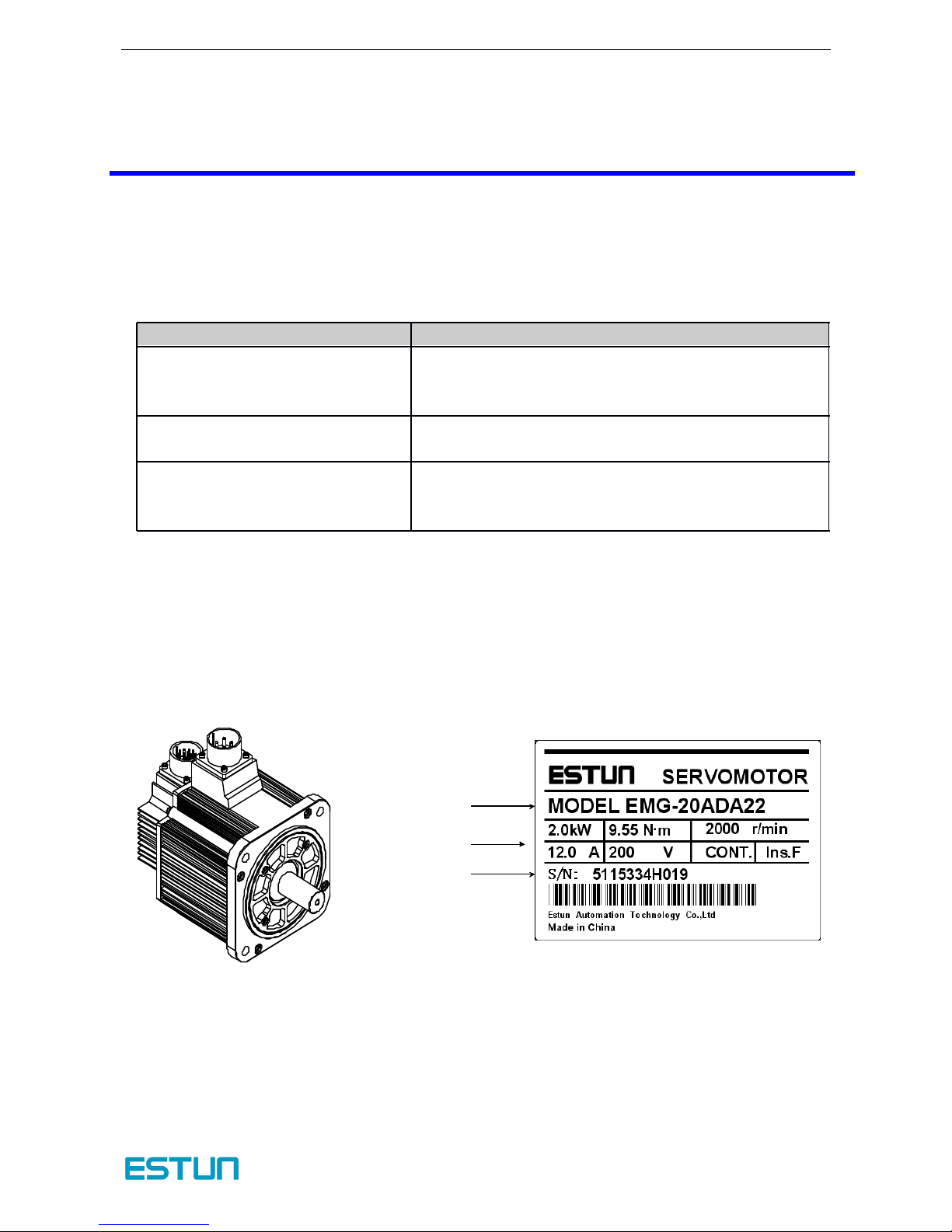
1.1.1 Servomotor
�
�
�
� Appearance
Appearance
Appearance
Appearance and
and
and
and Nameplate
Nameplate
Nameplate
Nameplate
Check
Check
Check
Check Items
Items
Items
Items
Comments
Comments
Comments
Comments
Are the delivered products the
ones that were ordered?
Check the model numbers marked on the nameplate on
the
servomotor and servodrive.
Is there any damage?
Check the overall appearance, and check for damage or
scratches that may have occurred during shipping.
Dose the servomotor shaft rotate
smoothly?
If the servomotor shaft is smoothly turned by hand, it is
normal. H owever, if the servomotor has brakes, it cannot
be turned manually.
{
Serial number
Ratings
Servomotor model
ProNet series AC servo system User’s manual V.1.08
- 8 -
�
�
�
� Servomotor
Servomotor
Servomotor
Servomotor Model
Model
Model
Model Designation
Designation
Designation
Designation
EMG
EMG
EMG
EMG –
–
–
– 10
10
10
10
A
A
A
A
D
D
D
D
A
A
A
A
1
1
1
1 1
1
1
1
Notes :
1. The EMG-30A□A □□,EMG-50A□A □□ servomotors are not mounted the incremental encoder.
2. There is no brake in EMG- □□ ADA □□ servomotor.
ESTUN Servomotor
【 1+2】【 3 】
【 4 】
【 5 】
【 6 】
【 7 】
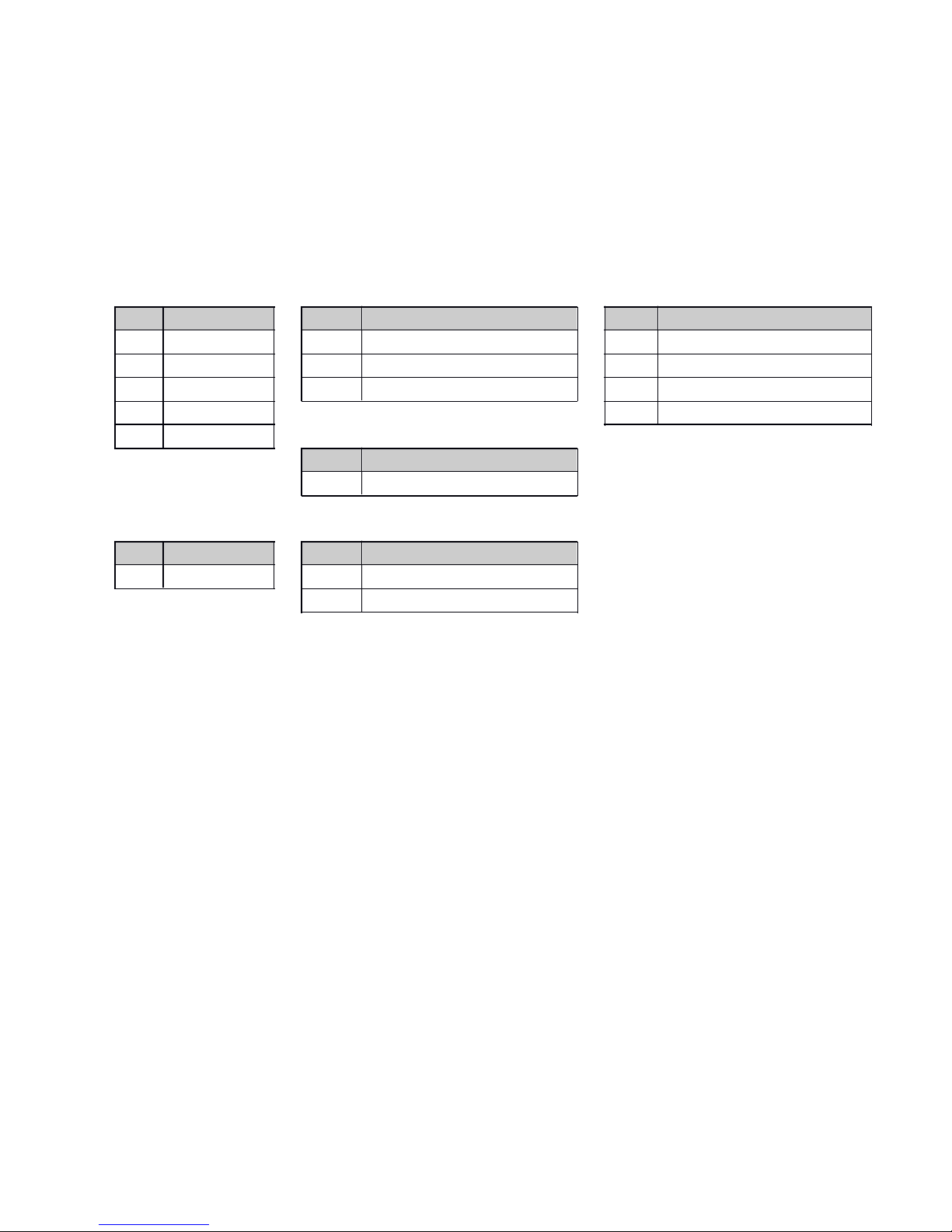
EMG M odel
【 1+2 】 Rated Output
【 4 】 Encoder
【 7 】 Option
Code
Rated Output
Code
Encoder
Code
Option101.0kWDIncremental encoder : 131072P/R
1
None
15
1.5kWSAbsolute encoder : 131072P/R
2
With oil sea l
20
2.0kWRResolver
3
With brake(DC 24V)
30
3.0kW4With oil sea l and brake(DC 24V )
50
5.0kW
【 5 】 Designing Sequence
Code
Designing Sequence
A
Designing sequence
【 3 】 V oltage
【 6 】 Shaft End
Code
Voltage
Code
Shaft End
A
200V AC
1
Straight without key(Standard)
2
Straight with key and tap

Contents
- 9 -
1.1.2 Servodrive
�
�
�
� Appearance
Appearance
Appearance
Appearance
ProNet-200W ~ 400W ProNet-750W-1.0KW
ProNet-1.5KW ProNet-2.0/3.0/5.0KW
CN3
CN3
CN3
CN3CN4
CN4
CN4
CN4
CN1
CN1
CN1
CN1
CN2
CN2
CN2
CN2
L1
L1
L1
L1
L2
L2
L2
L2
L3
L3
L3
L3
L 1C
L 1C
L 1C
L 1C
L 2C
L 2C
L 2C
L 2C
-
1
1
1
1
2
2
2
2
+
+
B1
B1
B1
B1
B2
B2
B2
B2
B3
B3
B3
B3
U
V
W
CHARGE
CHARGE
CHARGE
CHARGE
L1
L2
L3
CN3
CN3
CN3
CN3CN4
CN4
CN4
CN4
CN1
CN1
CN1
CN1CN2
CN2
CN2
CN2
L1C
L1C
L1C
L1C
L2C
L2C
L2C
L2C
B1
B2
B3
B3
B3
B3
U
V
W
+
-
1
+
2
CHAR GE
POWER
L1
L2
L3
CN3
CN3
CN3
CN3CN4
CN4
CN4
CN4
CN1
CN1
CN1
CN1CN2
CN2
CN2
CN2
L1C
L1C
L1C
L1C
L2C
L2C
L2C
L2C
B1
B2
B3
U
V
W
+
-
1
+
2
CHARGE POWER
ProNet series AC servo system User’s manual V.1.08
- 10 -
ProNet-7.5/11/15KW
�
�
�
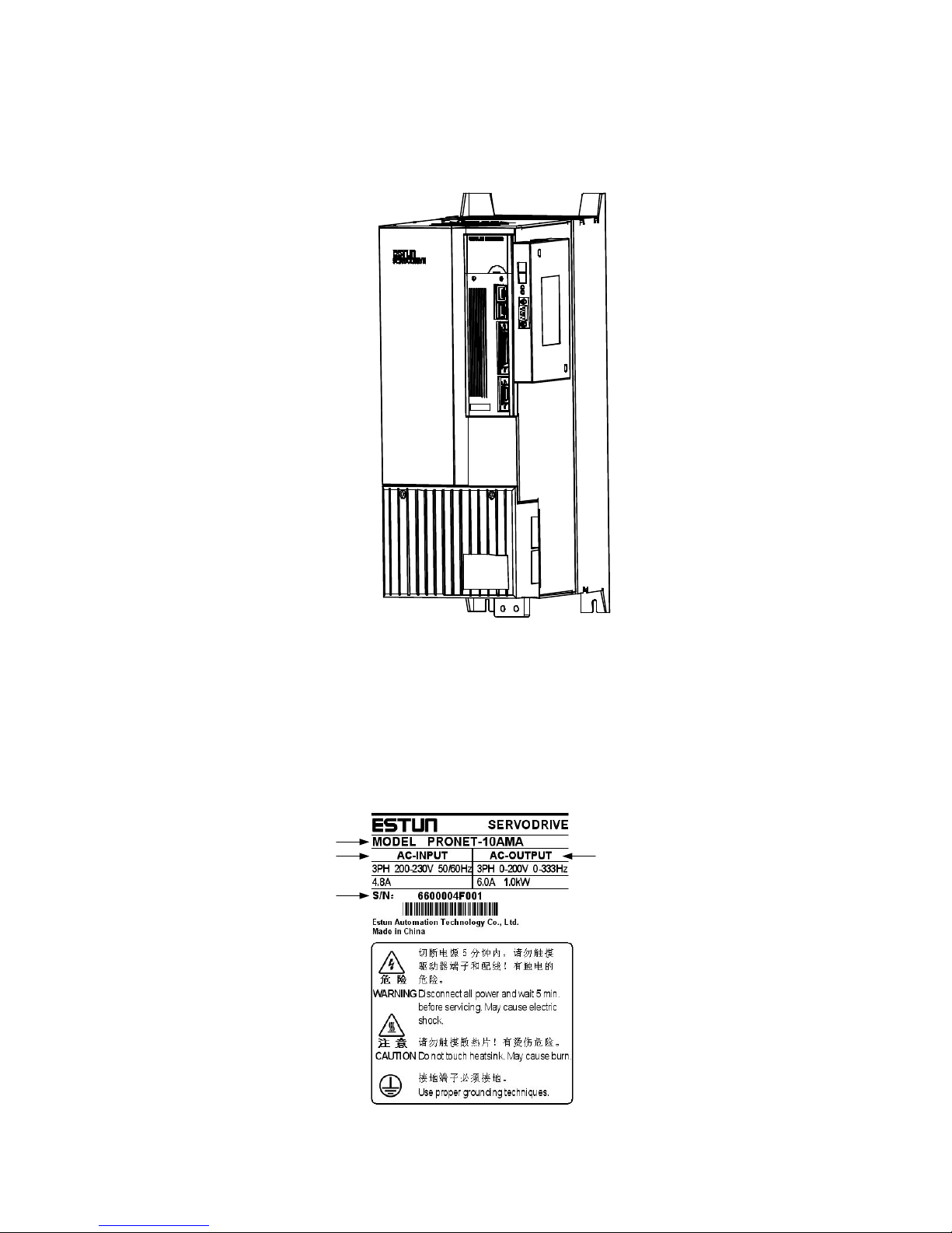
� Nameplate
Nameplate
Nameplate
Nameplate
CN3
CN3
CN3
CN3CN4
CN4
CN4
CN4
CN1
CN1
CN1
CN1CN2
CN2
CN2
CN2
Serv odrive m odel
Applic able
power
supply
Appl icable ser vomotor
capacity
Seri al number
Contents
-11-
�
�
�
� Servodrive
Servodrive
Servodrive
Servodrive Model
Model
Model
Model Designation
Designation
Designation
Designation
PRONET
PRONET
PRONET
PRONET –
–
–
– 10
10
10
10 A
A
A
A M
M
M
M A
A
A
A
1.2
1.2
1.2
1.2 Product
Product
Product
Product Part
Part
Part
Part Names
Names
Names
Names
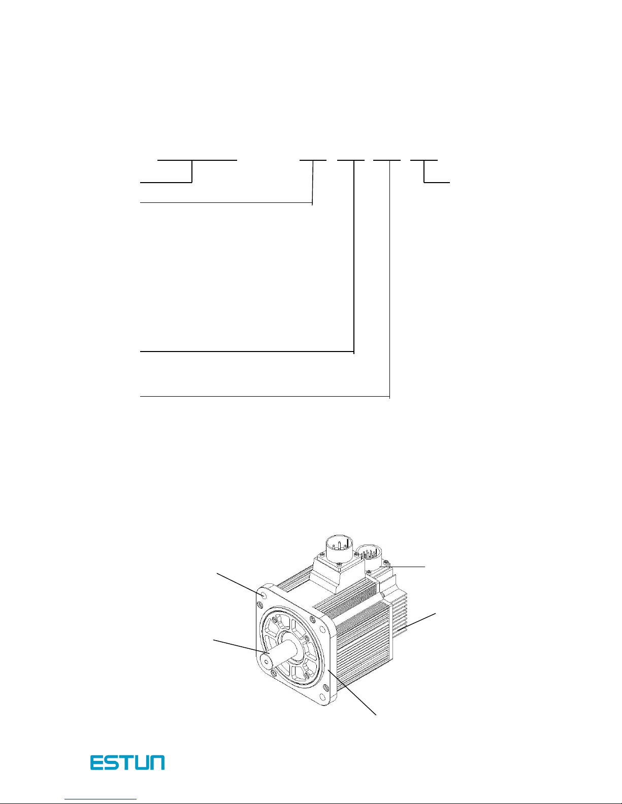
1.2.1 Servomotor
Servomotor w ithout gear and brake.
Rated
Rated
Rated
Rated Output
Output
Output
Output
02 0.2 kW
04 0.4 kW
08 0.75 kW
10 1.0 kW
15 1.5 kW
20 2.0 kW
30 3.0 kW
50 5.0 kW
75 7.5 kW1A11
kW
1E 15 kW
Voltage
Voltage
Voltage
VoltageA200VAC
D 400VA C
Control
Control
Control
Control M
M
M
M ode
ode
ode
ode
M Speed control, torque control, position control
E Speed control, torque contro l, position control (Support ex tended module)
Encoder
Encoder
Encoder
EncoderA17-bit serial encoder
B Resolver
ProNet
ProNet
ProNet
ProNet Model
Model
Model
Model
Encoder
Encoder
Encoder
Encoder
Shell
Shell
Shell
Shell
Flange
Flange
Flange
Flange
Output
Output
Output
Output
shaft
shaft
shaft
shaft
Mounting
Mounting
Mounting
Mounting
hole
hole
hole
hole
ProNet series AC servo system User’s manual V.1.08
- 12 -
1.2.2 Servodrive
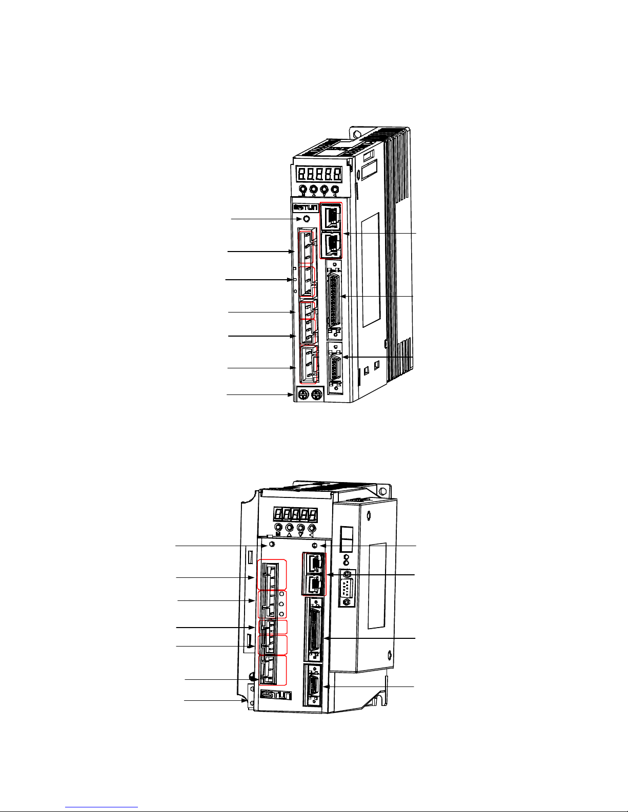
ProNet-200W ~ 400W
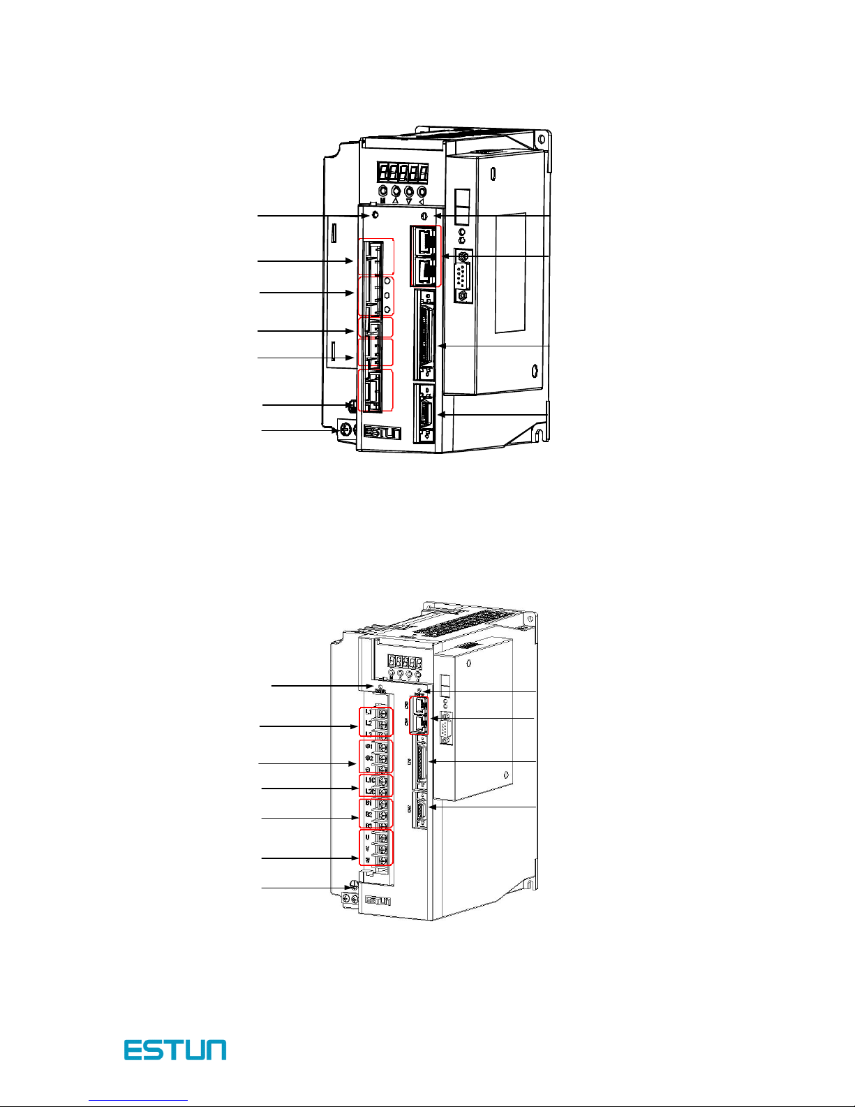
ProNet-750W ~ 1.0kW
Connector for communic ation
Connector for communic ation
Connector for communic ation
Connector for communic ation
Use d t o co mmunicate with o the r device s
.
I
I
I
I /
/
/
/
O signal c onnector
O signal c onnector
O signal c onnector
O signal c onnector
Use d f or ref eren ce inp ut
signa ls an d se qu ence I/O
signals
.
Encoder connec tor
Encoder connec tor
Encoder connec tor
Encoder connec tor
Co nn ects to t he en cod er
in th e se rvomoto r
.
Ground termina l
Ground termina l
Ground termina l
Ground termina l
Be sure t o co nn ect t o p rote ct
electric shock
.
Serv omotor terminals
Serv omotor terminals
Serv omotor terminals
Serv omotor terminals
Co nn ects to t he servomotor
power line
.
Re gener ative re sis tor
Re gener ative re sis tor
Re gener ative re sis tor
Re gener ative re sis tor
connec ting terminal s
connec ting terminal s
connec ting terminal s
connec ting terminal s
Use d t o co nn ect exte rnal
rege nera tive resisto rs
.
Control power supply
Control power supply
Control power supply
Control power supply
terminal s
terminal s
terminal s
terminal s
Used f or con trol po we r
supp ly inpu t
.
Connecting termina l
Connecting termina l
Connecting termina l
Connecting termina l
of DC reac tor
of DC reac tor
of DC reac tor
of DC reac tor
Ma in ci rcuit powe r
Ma in ci rcuit powe r
Ma in ci rcuit powe r
Ma in ci rcuit powe r
supply terminal s
supply terminal s
supply terminal s
supply terminal s
Used f or main circuit
power supp ly inpu t
.
Cha rge i ndicator
Cha rge i ndicator
Cha rge i ndicator
Cha rge i ndicator
Ligh ts whe n t he ma in circu it
power supp ly is ON an d
stays lit a s long a s th e main
circuit po wer sup ply
capa cit or remains cha rged
.
CN3
CN3
CN3
CN3CN4
CN4
CN4
CN4
CN1
CN1
CN1
CN1
CN2
CN2
CN2
CN2
L1
L1
L1
L1
L2
L2
L2
L2
L3
L3
L3
L3
L1C
L1C
L1C
L1C
L2C
L2C
L2C
L2C
-
1
1
1
1
2
2
2
2
+
+
B1
B1
B1
B1
B2
B2
B2
B2
B3
B3
B3
B3
U
V
W
CHA RGE
CHA RGE
CHA RGE
CHA RGE
Power on indicator
Power on indicator
Power on indicator
Power on indicator
Lights when the control power supply is
on
.
Connector for communication
Connector for communication
Connector for communication
Connector for communication
Used to communicate with other devices .
I
I
I
I /
/
/
/
O signal connector
O signal connector
O signal connector
O signal connector
Used for reference input
signals and sequence I /
O
signals
.
Encoder connector
Encoder connector
Encoder connector
Encoder connector
Connects to the encoder
in the servomotor .
Charge indicator
Charge indicator
Charge indicator
Charge indicator
Lights when the main circuit
power supply is ON and
stays lit as long as the main
circuit power supply
capacitor remains charged
.
Main circuit power
Main circuit power
Main circuit power
Main circuit power
supply terminals
supply terminals
supply terminals
supply terminals
Used for main circuit
power supply input .
Connecting terminal
Connecting terminal
Connecting terminal
Connecting terminal
of DC reactor
of DC reactor
of DC reactor
of DC reactor
Control power supply
Control power supply
Control power supply
Control power supply
terminals
terminals
terminals
terminals
Used for control power
supply input
.
Regenerative resistor
Regenerative resistor
Regenerative resistor
Regenerative resistor
connecting terminals
connecting terminals
connecting terminals
connecting terminals
Used to connect external
regenerative resistors
.
Ground terminal
Ground terminal
Ground terminal
Ground terminal
Be sure to connect to protect
electric shock
.
Servomotor terminals
Servomotor terminals
Servomotor terminals
Servomotor terminals
Connects to the servomotor
power line
.
L1
L2
L3
CN3
CN3
CN3
CN3CN4
CN4
CN4
CN4
CN1
CN1
CN1
CN1CN2
CN2
CN2
CN2
L1C
L1C
L1C
L1C
L2C
L2C
L2C
L2C
B1
B2
B3
U
V
W
+
-
1
+ 2
CHAR GE
POW ER
Contents
- 13 -
ProNet-1.5kW
ProNet-2.0kW ~ 5.0kW
Power on indicator
Power on indicator
Power on indicator
Power on indicator
Lights when the control power supply is
on
.
Connector for communication
Connector for communication
Connector for communication
Connector for communication
Used to communicate with other devices
.
I
I
I
I /
/
/
/
O signal connector
O signal connector
O signal connector
O signal connector
Used for reference input
signals and sequence I/O
signals
.
Encoder connector
Encoder connector
Encoder connector
Encoder connector
Connects to the encoder
in the servomotor
.
Charge indicator
Charge indicator
Charge indicator
Charge indicator
Lights when the main circuit
power supply is ON and
stays lit as long as the main
circuit power supply
capacitor remains charged
.
Main circuit power
Main circuit power
Main circuit power
Main circuit power
supply terminals
supply terminals
supply terminals
supply terminals
Used for main circuit
power supply input
.
Connecting terminal
Connecting terminal
Connecting terminal
Connecting terminal
of DC reactor
of DC reactor
of DC reactor
of DC reactor
Control power supply
Control power supply
Control power supply
Control power supply
terminals
terminals
terminals
terminals
Used for control power
supply input
.
Regenerative resistor
Regenerative resistor
Regenerative resistor
Regenerative resistor
connecting terminals
connecting terminals
connecting terminals
connecting terminals
Used to connect external
regenerative resistors
.
Ground terminal
Ground terminal
Ground terminal
Ground terminal
Be sure to connect to protect
electric shock
.
Servomotor terminals
Servomotor terminals
Servomotor terminals
Servomotor terminals
Connects to the servomotor
power line
.
L1
L2
L3
CN3
CN3
CN3
CN3CN4
CN4
CN4
CN4
CN1
CN1
CN1
CN1CN2
CN2
CN2
CN2
L1C
L1C
L1C
L1C
L2C
L2C
L2C
L2C
B1
B2
B3
U
V
W
+
-
1
+
2
CHARGE
POWER
Cha rge i ndicator
Cha rge i ndicator
Cha rge i ndicator
Cha rge i ndicator
Ligh ts when t he main circuit
power supp ly is ON an d
stays lit a s long a s th e main
circuit po wer sup ply
capa cit or remains cha rged
.
Main ci rcuit power
Main ci rcuit power
Main ci rcuit power
Main ci rcuit power
supply terminal s
supply terminal s
supply terminal s
supply terminal s
Used f or m ain circuit
power supp ly inpu t
.
Connecting termina l
Connecting termina l
Connecting termina l
Connecting termina l
of DC reac tor
of DC reac tor
of DC reac tor
of DC reac tor
Control power supply
Control power supply
Control power supply
Control power supply
terminal s
terminal s
terminal s
terminal s
Used f or con trol po we r
supp ly inpu t
.
Re gener ative re sis tor
Re gener ative re sis tor
Re gener ative re sis tor
Re gener ative re sis tor
connec ting terminal s
connec ting terminal s
connec ting terminal s
connec ting terminal s
Use d t o co nn ect exte rnal
rege nera tive resisto rs
.
Ground termina l
Ground termina l
Ground termina l
Ground termina l
Be sure t o co nn ect t o p rote ct
electric shock
.
Serv omotor terminals
Serv omotor terminals
Serv omotor terminals
Serv omotor terminals
Co nn ects to t he servomot or
power line
.
Power on indica tor
Power on indica tor
Power on indica tor
Power on indica tor
Ligh ts whe n t he con trol po we r supp ly is
on
.
Connector for communic ation
Connector for communic ation
Connector for communic ation
Connector for communic ation
Use d t o co mmunicate with o the r device s
.
I
I
I
I /
/
/
/
O signal c onnector
O signal c onnector
O signal c onnector
O signal c onnector
Use d f or ref eren ce inp ut
signa ls an d se qu ence I/O
signals
.
Encoder connec tor
Encoder connec tor
Encoder connec tor
Encoder connec tor
Co nn ects to t he en cod er
in the servomotor
.

ProNet series AC servo system User’s manual V.1.08
- 14 -
ProNet-7.5kW ~ 15kW
Power on indicator
Power on indicator
Power on indicator
Power on indicator
Lights when the control power supply is
on
.
Connector for communication
Connector for communication
Connector for communication
Connector for communication
Used to communicate with other devices
.
I
I
I
I /
/
/
/
O signal connector
O signal connector
O signal connector
O signal connector
Used for reference input
signals and sequence I/O
signals
.
Encoder connector
Encoder connector
Encoder connector
Encoder connector
Connects to the encoder
in the servomotor
.
Charge indicator
Charge indicator
Charge indicator
Charge indicator
Lights when the main circuit
power supply i s O N and
stays lit as long as the main
circuit power supply
capacitor remains charged
.
CN3
CN3
CN3
CN3
CN4
CN4
CN4
CN4
CN1
CN1
CN1
CN1CN2
CN2
CN2
CN2
CHARGE
POWER

- 15 -
Chapter 2
Installation
2.1 Servomotor
Servomotor can be installed either horiz ontally or vertically. H owever, if the servomotor is installed
incorrectly , the service life of the servomotor will be shortened or unexpected problems will occur.
Please observe the installation instructions described below to install the servomotor correctly.
2.1.1 Storage
When the servomotor is not used, store it in the temperature between -20 ℃ and 60 ℃ w ith the
power cable disconnected.
2.1.2 Installation Sites
The servomotor is designed for indoor use.Install the servomotor in an environment which meets
the following conditions.
Free from corrosive and explosive gases.
Well-ventilated and free from dust and moisture.
Ambient temperature from 0 to 40 ℃ .
Relative humidity from 26% to 80%( non-condensing).
Facilitates inspection and cleaning.
Before
Before
Before
Before installation:
installation:
installation:
installation:
Anticorrosive paint is coated on the edge of the servomotor shaft. Clean off the anticorrosive paint
thoroughly using a cloth moistened w ith thinner.
Avoid getting thinner on other parts of the servomotor when cleaning the shaft.
Anticorrosive paint
Anticorrosive paint
Anticorrosive paint
Anticorrosive paint
ProNet series AC servo system User’s manual V.1.08
- 16 -
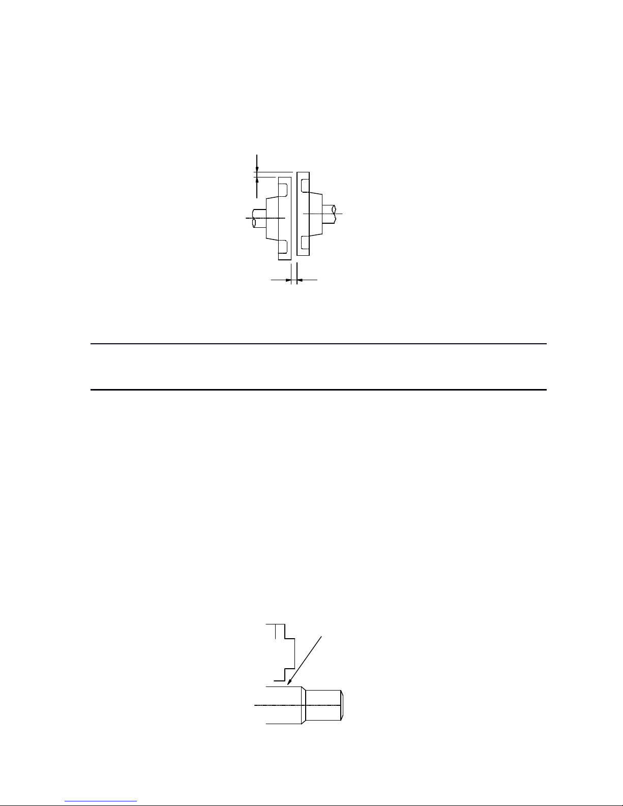
2.1.3 Installation Alignment
Align the shaft of the servomotor with that of the machinery to be controlled, and then connect the
shafts with elastic couplings. Install the servomotor so that alignment accurancy falls within the
range shown below.
Measure this distance
at
four different positions in the circumference. The difference between the
maximum and minimum measurements must be 0.03mm or less.(Turn together with couplings.)
2.1.4 Installation Orientation
Servomotor can be installed ethier horiz ontally or vertically.
2.1.5 Handling
Oil
and Water
If the servomotor is used in a location that is subject to water or oil drops, make sure of the
servomotor protective specification. If the servomotor is required to meet the protective
specification to the through shaft section by default, use a servomotor with an oil seal.
Through
Through
Through
Through shaft
shaft
shaft
shaft section:
section:
section:
section:
It refers to the gap where the shaft protrudes from the end of the servomotor.
Note:
Note:
Note:
Note:
·
If the alignment accurancy is incorrect,vibration will occur, resulting in damage to the bearings.
·
Mechanical shock to the shaft end is forbidden, otherwise it may result in damage to the encoder of the servomotor.
Through Shaft Section

Chapter 2 Installation
- 17 -
2.1.6 Cable
Tension
When connecting the cables, the bending radius should not be too small, do not bend or apply
tension to cables.
Since the conductor of a signal cable is very thin (0.2 to 0.3 mm), handle it with adequate care.
2.2 Servodrive
ProNet series servodrive is a base-mounted type. Incorrect installation w ill cause problems. Always
observe the installation instructions described below.
2.2.1 Storage
When the servodrive is not used, store it in the temperature between -20 ℃ and 85 ℃ w ith the
power cable disconnected.
2.2.2 Installation Sites
Notes on installation are shown below.
Situation
Situation
Situation
Situation
Notes
Notes
Notes
Notes on
on
on
on installation
installation
installation
installation
When installed in a control
panel
Design the control panel siz e, unit layout, and cooling method so that the temperature
around the periphery of the serv odrive does not exceed 55 ℃
.
When installed near a
heating unit
Suppress radiation heat from the heating unit and a temperature rise caused by
convection so that the temperature around the periphery of the servodrive does not
exceed 55 ℃
.
When installed near a
source of vibration
Install a vibration iso lator underneath the serv odrive to prevent it from recev ing vibration.
When installed in a location
subject to corrosive gases
Take appropriate action to prevent corrosive gases. Corrosive gases do not immediately
affect the servodrive, but will eventually cause contactor-related devices to malfunction.
Others
Avoid installation in a hot
and
humid site or where excessive dust or iro n powder is
present in the air.

ProNet series AC servo system User’s manual V.1.08
- 18 -
2.2.3 Installation Orientation
Install the servodrive perpendicular to the w all as shown in the figure. The servodrive must be
oriented this way because it is designed to be cooled by natural convection or a cooling fan if
required. Firmly secure the servodrive through two mounting holes.
2.2.4 Installation Method
When installing multiple servodrives side by side in a control panel, observe the following
installation method.
Cooling Fan
Cooling Fan
Colling Fan
Colling Fan
Wall
Ventilation

Chapter 2 Installation
- 19 -
■
■
■
■
Installation
Installation
Installation
Installation Orientation
Orientation
Orientation
Orientation
Install servodrive perpendicular to the w all so that the front panel (containing connectors) faces
outward.
■
■
■
■
Cooling
Cooling
Cooling
Cooling
Provide sufficient space around each servodrive to allow cooling by natural convection or fans.
■
■
■
■
Installing
Installing
Installing
Installing side
side
side
side by
by
by
by side
side
side
side
When installing servodrives side by side, provide at least 10 mm space between them and at least
50 mm space above and below them as shown in the figure above. Make sure that the temperature
inside the control panel is evenly, and prevent the temperature around each servodrive from
increasing excessively. Install cooling fans above the servodrives if required.
■
■
■
■
Working
Working
Working
Working conditions
conditions
conditions
conditions
1.Temperature : 0~ 55 ℃
2.Humidity : 90%RH or less
3.Vibration : 4.9m/s2or less
4.Ambient temperature to ensure long-term reliability: 45 ℃ or less
- 20 -
Chapter 3
Wiring
3.1 Main Circuit Wiring
Please observe the following instructions while wiring the main circuit.
3.1.1 Names and Functions of Main Circuit T erminals
· Do not bundle or run power and signal lines together in the same duct. Keep power and
signal lines separated by at least 300 mm.
· U se twisted-pair shielded wires or multi-core twisted-pair shielded wires for signal and
encoder feedback lines.
· The maximum length is 3 m for reference input lines and is 20 m for encoder feedback lines.
· Do not touch the power terminals for 5 minutes after turning power OFF because high
voltage may still remain in the servodrive.
Terminal
Terminal
Terminal
Terminal
Symbol
Symbol
Symbol
Symbol
Name
Name
Name
Name
Main
Main
Main
Main C ircuit
Circuit
Circuit
Circuit
Voltage(V)
Voltage(V)
Voltage(V)
Voltage(V)
ProNet-
ProNet-
ProNet-
ProNet-
Functions
Functions
Functions
Functions
L1 , L2 , L3
Main circuit
power supply
input terminal
200
□□ A
Three-phase 200 ~ 230VAC+10% -15% (50/60Hz)
400
□□ D
Three-phase 380 ~ 440VAC+10% -15% (50/60Hz)
U , V , W
Servomotor
connection
terminals
--Connects to the serv omotor.
L1C , L2C
Control circuit
power supply
input terminal
200
□□ A
Single-phase 200 ~ 230VAC+10% -15% (50/60Hz)
400
□□ D
Single-phase 380 ~ 440VAC+10% -15% (50/60Hz)
Ground terminals
-
-
Connects to the power supply ground terminals and
servomotor gro und terminal.
B1 , B2 ,
B3
External
regenerative
resistor
connection
terminal
200
□□ A
If use an internal regenerative resistor, please short B2
and B3. Remove the wire between B2 and B3 and
connect an external regenerative resistor(provided by
customer) between B1 and B2, if the capacity of the
internal regenerative resistor is incufficien t.
B1 , B2
400
□□ D
Connect an external regenerative resistor between B1
and B2.
+
○ 1,+○ 2
DC reactor for
harmonic
suppression
terminal
200
□□ A
Normally short
+
○
1and
+
○
2.
If a countermeasure against power supply harmonic
waves is needed, connect a DC reactor between
+
○ 1and+○ 2.
-
○
Main circuit
minus terminal
200
□□ A
Normally not connected.
!
CAUTION
Chapter 3 Wiring
- 21 -
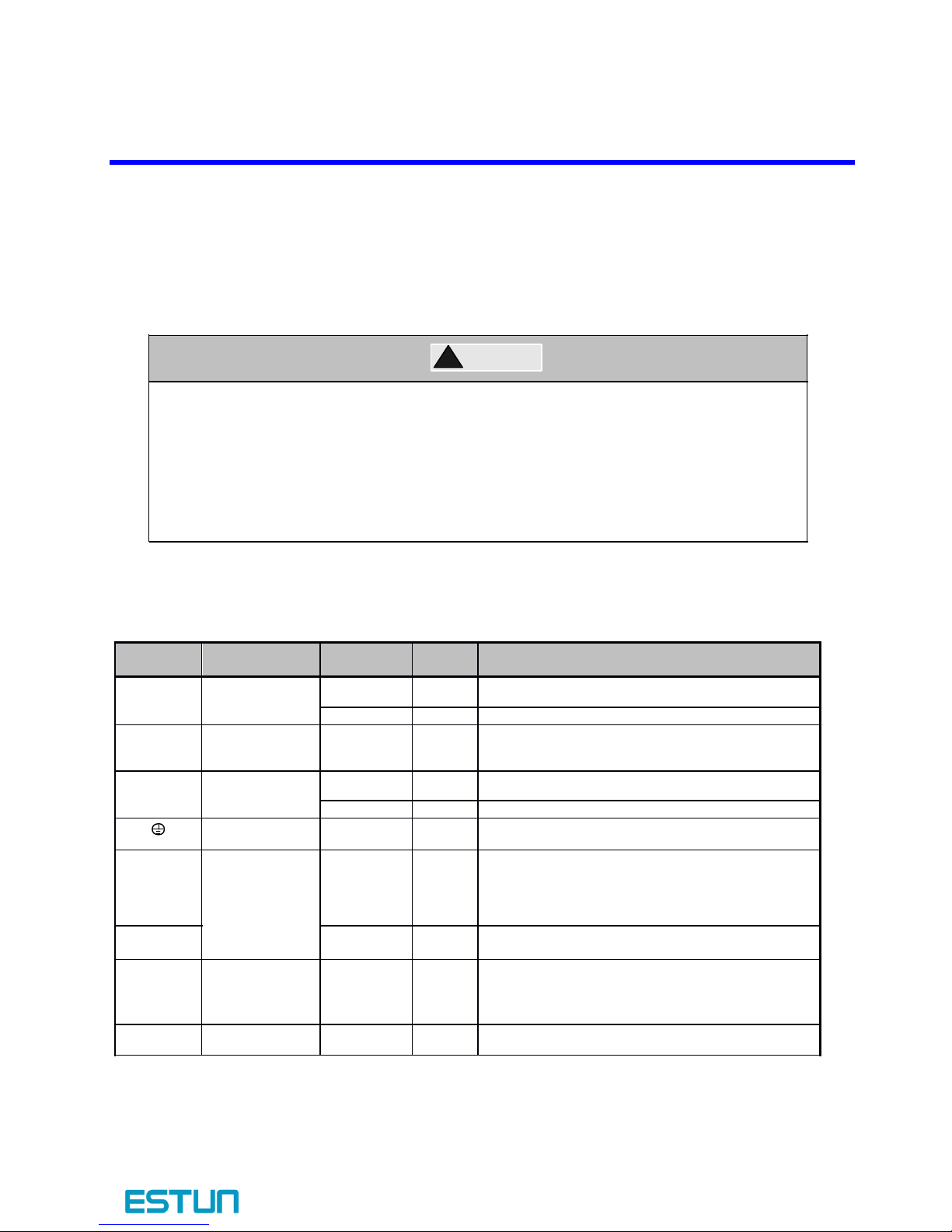
3.1.2
Typical
Main Circuit Wiring Examples
Three-phase 200V ProNet-02A ~ 04A
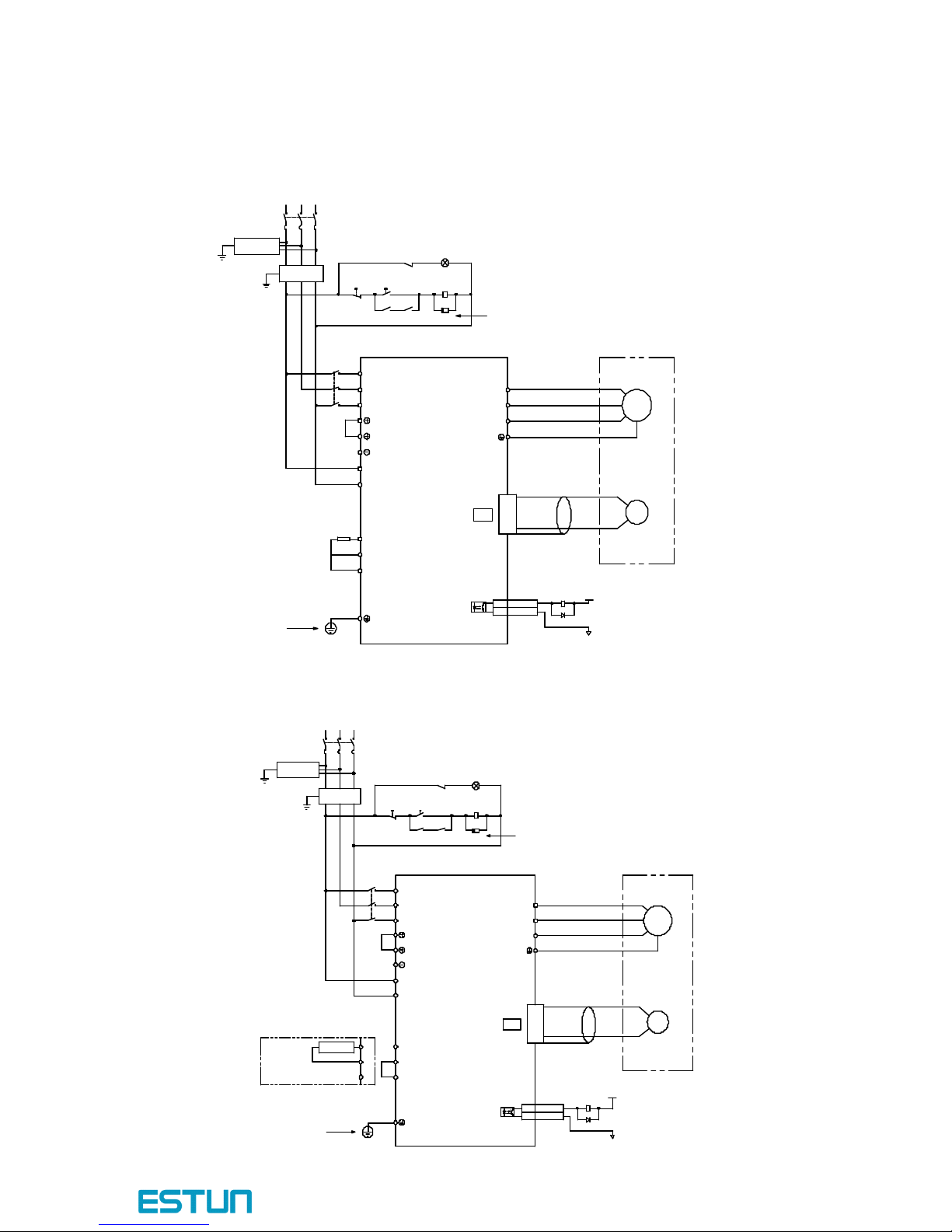
Three-phase 200V ProNet-08A ~ 50A
L1 L2 L3
Th ree-pha se 200~2 30V (50/60H z)
+
10%
-
15%
Powe r OF F
Powe r ON
1 KM 1SU P
1 KM
1 Ry
L
1
L2
L3
W
V
U
M
PG
A(1)
B(2)
C(3)
D(4)
L2C
L1C
CN2
1 Ry1D+24 V
0 V
1 Ry
1PL ( Servo Alarm Di splay )
ALM+
7
ALM-
8
ProNe t
ProNe t
ProNe t
ProNe t
Serie s Servo drive
1
2
B1
B2
B3
External Reg enerative Resi stor
Ground Terminal
Encod er
Servod rive
Magn etic Contactor
Mold ed-case Ci rcuit Breaker
Surge Protector
Surge Protector
Surge Protector
Surge Protector
Noi se Filter
Be sure to conn ect a surge supp ressor to the
excitatio n coil of the magne tic contactor an d relay.
Noi se Filt er
L1 L2 L3
Th ree-pha se 20 0~230 V (50/ 60Hz)
+ 10%
- 15%
Power OF F
Powe r ON
1
KM
1SUP
1
KM
1 Ry
L
1
L2
L3
W
V
U
M
PG
Servom ot or
Encod er
A(1)
B(2)
C(3)
D(4)
L2C
L1C
CN2
1 Ry
1D
+24 V
0 V
Surge Protect or
Magnetic Contactor
M olded -case C ircuit Breake r
1 Ry
1PL (
Servo Alarm Di splay
)
ALM+
7
ALM -
8
Be sure t o co nnect a surge suppresso r to th e
excitat ion coil of the magn etic con tact or an d rel ay.
.
ProNet
ProNet
ProNet
ProNet
Series Servodrives
1
2
B1
B2
B3
B2
B1
External Regenerator Resistor
B3
Ground Terminal
ProNet series AC servo system User’s manual V.1.08
- 22 -
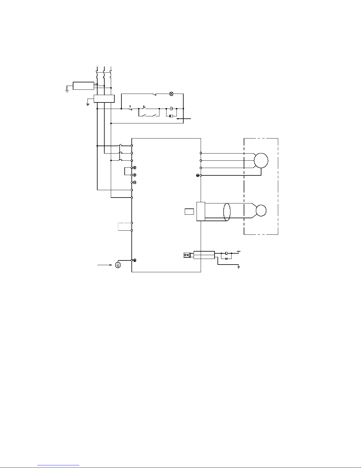
Three-phase 400V ProNet-75D ~ 1ED
L1 L2 L3 Three-phase 380~440V (50/60Hz)
+
10%
-
15%
Power OFF Power ON
1 KM 1SUP
1 KM
1
Ry
L 1
L2
L3
W
V
U
M
PG
A(1)
B(2)
C(3)
D(4)
L2C
L 1 C
CN2
1
Ry
1D
+24 V
0 V
1
Ry
1PL ( Ser vo Alarm Display )
ALM+7
ALM-
8
ProNet
ProNet
ProNet
ProNet
Series Servodrive
1
2
B1
B2
External Regenerativ e Resistor
Ground Terminal
Encoder
Servodrive
Magnetic Contactor
Surge Protector
Surge Protector
Surge Protector
Surge Protector
Noise Filter
Be sure to connect a surge s uppress or to the
excitation coil of the magnetic contactor and relay.
- 23 -
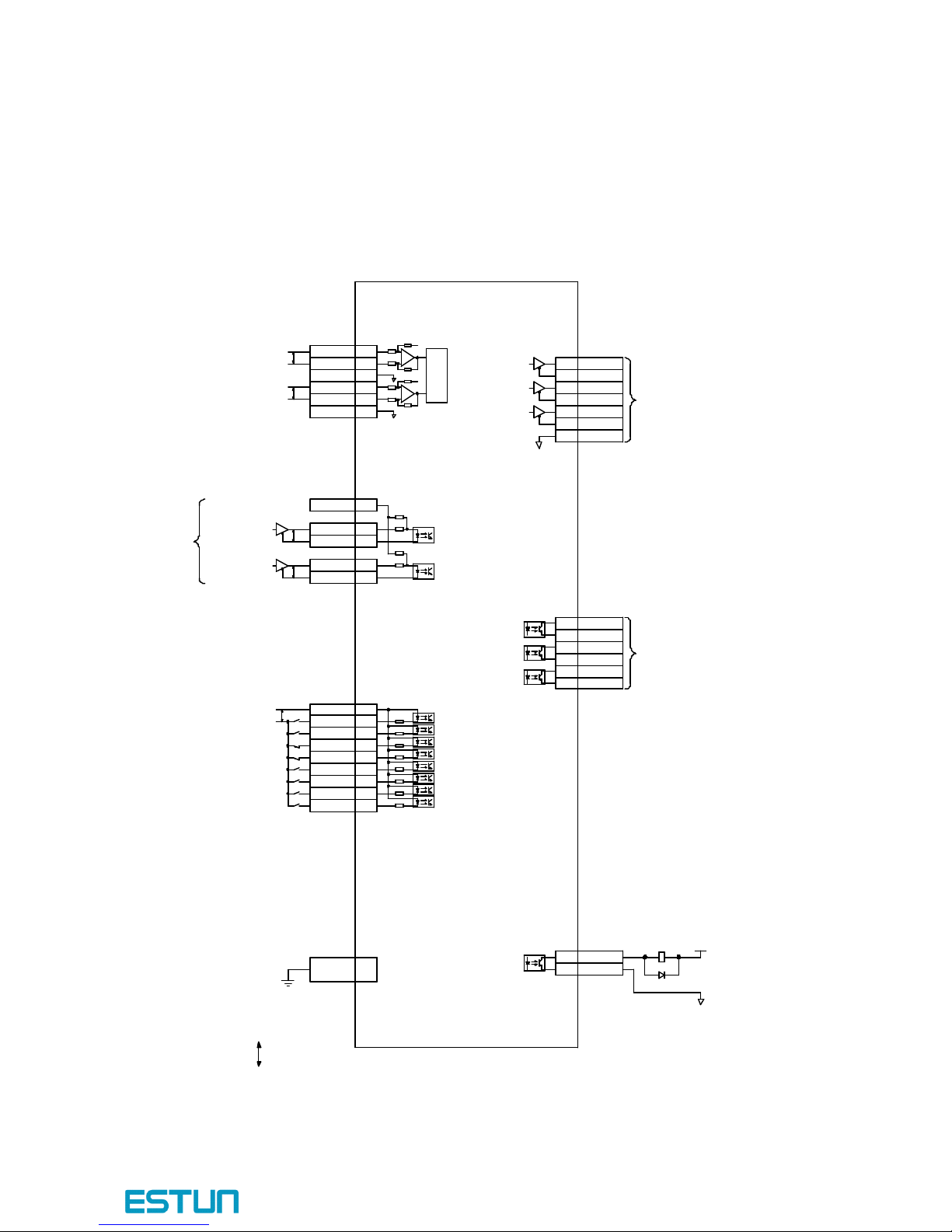
3.2 I/O Signals
3.2.1 Examples of I/O Signal Connections
+
A/D
2KΩ
150Ω
150Ω
3.3KΩ
2KΩ
PULS
/ CW /
A
SIGN
/
CCW
/
B
Co nn ect Shie ld to C on nect or Sh ell
Open-Col lector Reference Use
Speed Refe re nce(± 1V~1 0V/Rated Sp ee d)
Torque Reference(±1V~10V/Rated Torque)
Position Reference
Signal Allocations can be Modified:
S-ON: Servo ON
P-CON: Proportion Control
P-OT:Forward Run Prohibited
N-OT:Reverse Run Prohibited
ALM-RST: Alarm Reset
CLR: Clear Error Pulse
P-CL:Forward Torque Limit
N-CL:Reverse Torque Limit
+2 4 V
P P P P
PG Divide d R atio Outpu t
App licable Line Ou tpu t
AM26L S32 A Man ufa ctured by TI or the Equ ivalen t.
Sign al Alloca tion s can be Modifie d:
V- CMP: Sp eed Coincid ence
COIN : Po sitionin g C ompletion
TGON:R ota tion D ete ction
S-RDY: Servo Read y
CLT :T or que L imit Detectio n
BK:B ra ke Inte rlo ck
PGC: E nco der C- Pulse Outpu t
P
Repr esents T wisted-p air Wires
ALM: Ser vo Alar m Output
Pho toco upler Output :
Maximum Opera ting Vo ltage :DC3 0V
Maximum Output Cur re nt: DC50mA
-
-
+
ref
ref
40K
10K
40K
10K
1
Ry
1D
+24
V
0
V
PAO+20
PAO-21
PBO+22
PBO-23
PCO+24
PCO-25
DGND
50
TGON+
5
TGON- 6
S-RDY+ 9
S-RDY- 10
V-CMP+ 11
V-CMP- 12
ALM+ 7
ALM-8
VREF+ 1
VREF- 2
AGND 3
TREF+
26
TREF-
27
AGND 28
PPI 34
PULS+ 30
PULS- 31
SIGN+ 32
SIGN- 33
DICOM
13
S-ON 14
P-CON 15
P-OT 16
N-OT 17
ALM-RST 39
CLR
40
P-CL 41
N-CL 42
Shield
ProNet
ProNet
ProNet
ProNet
Series Servodrive

ProNet series AC servo system User’s manual V.1.08
- 24 -
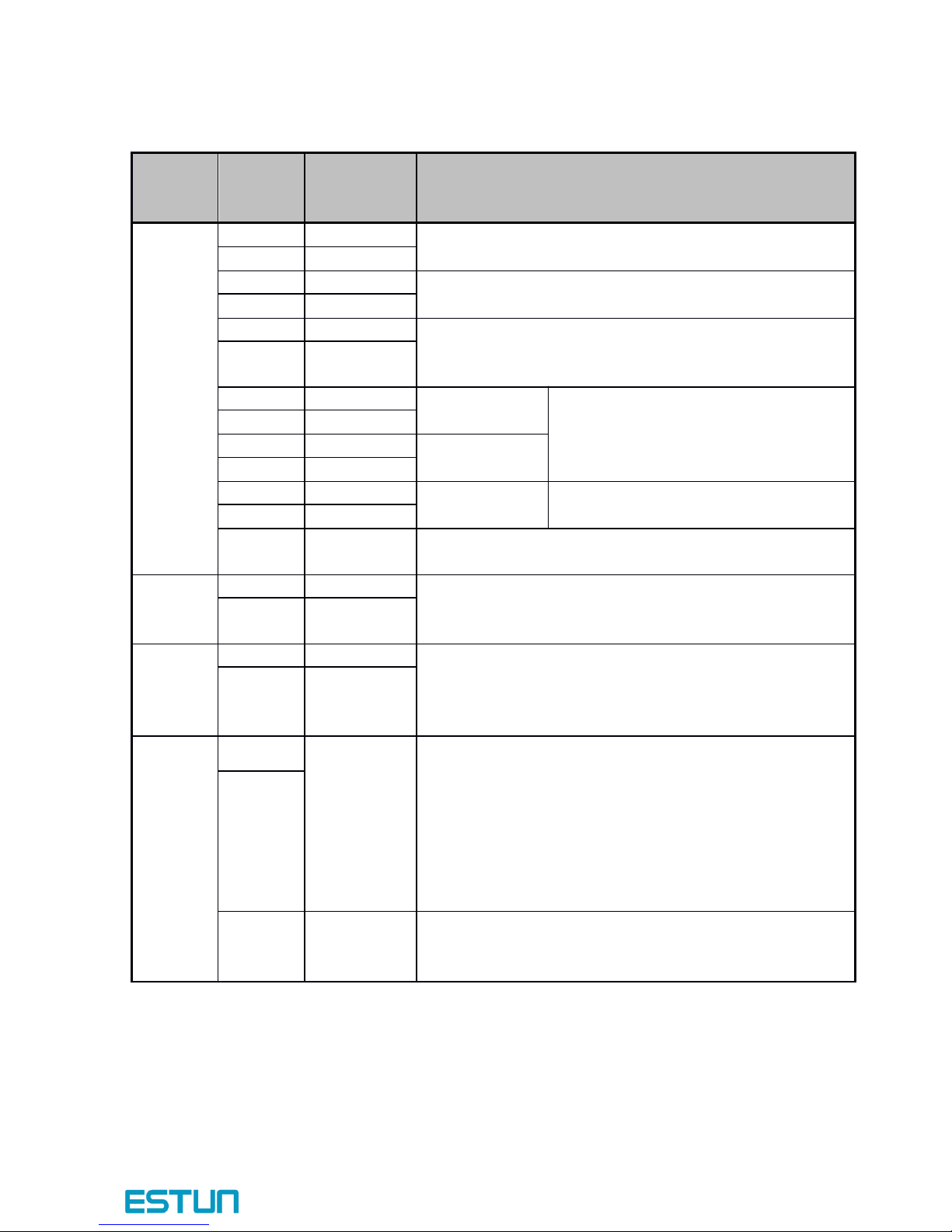
3.2.2 I/O Signal Names and Functions
�
�
�
� Input
Input
Input
Input Signals
Signals
Signals
Signals
Control
Control
Control
Control
Mode
Mode
Mode
Mode
Signal
Signal
Signal
Signal
Name
Name
Name
Name
Pin
Pin
Pin
Pin No
No
No
No .
.
.
.
Function
Function
Function
Function
Speed
Position
Torque
/S-ON14Servo ON: Turns the servomotor on.
/P-CON
15
Function selected by parameter.
Proportional
control reference
Switches the speed control loop from PI to P control when
ON.
Direction
reference
With the internally set speed selection: Switch the rotation
direction.
Control mode
switching
Enables control mode switching.
Z ero-clamp
reference
Speed control with z ero-clamp function: Reference speed is
z ero when ON.
Reference pulse
block
Position control with reference pulse: Stops reference pulse
input when ON.
P-OT
N-OT1617
Forward run
prohibited
Reverse run
prohibited
Overtravel prohibited: Stops serv omotor when ON.
/PCL
/NCL4142
Function selected by parameter.
Forward external
torque limit ON
Reverse external
torque limit ON
Current limit function enabled when ON.
Internal speed
switching
With the internally set speed selection: Switches the internal
speed settings.
/ALM-RST
39
Alarm reset: Releases the servo alarm state.
DICOM
13
Control power supply input for I/O signals: Provide the +24V DC power supply
Speed
VREF+
1
Speed reference input: ± 10V.
VREF-
2
Position
PULS+
30
Pulse reference input mode :
Sign + pulse string
CCW + CW pulse
Two-phase pulse (90ºphase differential)
PULS-31SIGN+
32
SIGN-
33
PPI
34
Power supply input for open collector reference (2K Ω /0.5W resistor is built into
the servodrive).
/CLR
40
Positional error pulse clear input: Clears the positional error pulse during position
control.
Torque
T-REF+
26
Torque reference input: ± 10V.
- 25 -
�
�
�
� Output
Output
Output
Output signals
signals
signals
signals
Control
Control
Control
Control
Mode
Mode
Mode
Mode
Signal
Signal
Signal
Signal
Name
Name
Name
Name
Pin
Pin
Pin
Pin No.
No.
No.
No.
Function
Function
Function
Function
Speed
Speed
Speed
Speed
Position
Position
Position
Position
Torque
Torque
Torque
Torque
/TGON+
5
Detects when the servomotor is rotating at a speed higher
than the motor speed seeting.
/TGON-
6
ALM+
7
Servo alarm:
Turns off when an error is detected.
ALM-
8
/S-RDY+
9
Servo ready:
ON if there is no servo alarm when the control/main circuit
power supply is turned ON.
/S-RDY-
10
PAO+
20
Phase-A signal
Converted two-phase pulse(phases A and
B) encoder output.
PAO-
21
PBO+
22
Phase-B signal
PBO-23PCO+
24
Phase-C signal
Z ero-point pulse(Phase-C) signal
PCO-
25
FG
Shell
Connected to frame ground if the shield wire of the
I/O signal cable is connected to the connector shell.
Speed
Speed
Speed
Speed
/V-CMP+
11
Speed coincidence:
Detects whether the motor speed is w ithin the setting range
and if it matches the reference speed value.
/V-CMP-
12
Position
Position
Position
Position
/COIN +
11
Positioning completion:
Turns ON when the number of positional error pulses reaches
the value set. The setting is the number of positional error
pulses set in the reference units.
/COIN -
12
Reserved
Reserved
Reserved
Reserved
/CLT
—
Reserved terminals:
The functions allocated to /TGON, /S-RDY, and /V-CMP
(/COIN) can be changed by using the parameters.
/CLT: Torque limit output
Turns on when it reaches the value set.
/BK: Brake interlock output
Releases the brake when ON,
/BK
—
4,18,19,29,35
36,37,38,43
44,45,47,49
Not used.

ProNet series AC servo system User’s manual V.1.08
- 26 -
3.2.3 I/O Signal Connector (CN1) Terminal Layout
Note:
Note:
Note:
Note: The functions allocated to the following input and output signals can be changed by using the
parameters.
· Input signals: /S-ON , /P-CON , P-OT , N-OT , /ALM-RST , /CLR , /PCL , /NCL
· Output signals: /TGON , /S-RDY , /COIN
Please refer to A.3
A.3
A.3
A.3 Parameters
Parameters
Parameters
Parameters in
in
in
in details
details
details
details for detailed information.
Term inal
Term inal
Term inal
Term inal
No.
No.
No.
No.
Name
Name
Name
Name
Function
Function
Function
Function
Term inal
Term inal
Term inal
Term inal
No.
No.
No.
No.
Name
Name
Name
Name
Function
Function
Function
Function
1
VREF+
Speed reference input: ± 10V
26
T-REF+
Torque reference
input: ± 10V
2
VREF-
27
T-REF-3AGND
AGND28AGND
AGND4—
Reserved29—
Reserved
5
/TGON+
Running signal output
30
PULS+
Reference pulse input
6
/TGON-
31
PULS-
7
ALM+
Servo alarm
32
SIGN+
Reference sign input
8
ALM-
33
SIGN-
9
/S-RDY+
Servo ready
34
PPI
Open collector
reference power supply
10
/S-RDY-
35—Reserved
11
/COIN +
Positioning completion
36—Reserved
12
/COIN -37—
Reserved
13
DICOM
I/O signal power supply 24V
DC
38—Reserved
14
/S-ON
Servo ON
39
/ALM-
RST
Alarm reset
15
/P-CON
P/PI control input
40
/CLR
Position error pulse
clear input
16
P-OT
Forward run prohibit input
41
/PCL
Forward torque limit
input
17
N-OT
Reverse run prohibit run
42
/NCL
Reverse torque limit
input18—
Reserved43—
Reserved
19—Reserved44—
Reserved
20
PAO+
PG dividing
pulse output
phase A
PG dividing
pulse
output
45—Reserved
21
PAO-
46
DGND
DGND
22
PBO+
PG dividing
pulse output
phase B47—
Reserved
23
PBO-
48
DGND
DGND
24
PCO+
PG dividing
pulse output
phase C
Z ero-point
pulse
49—Reserved
25
PCO-
50
DGND
DGND
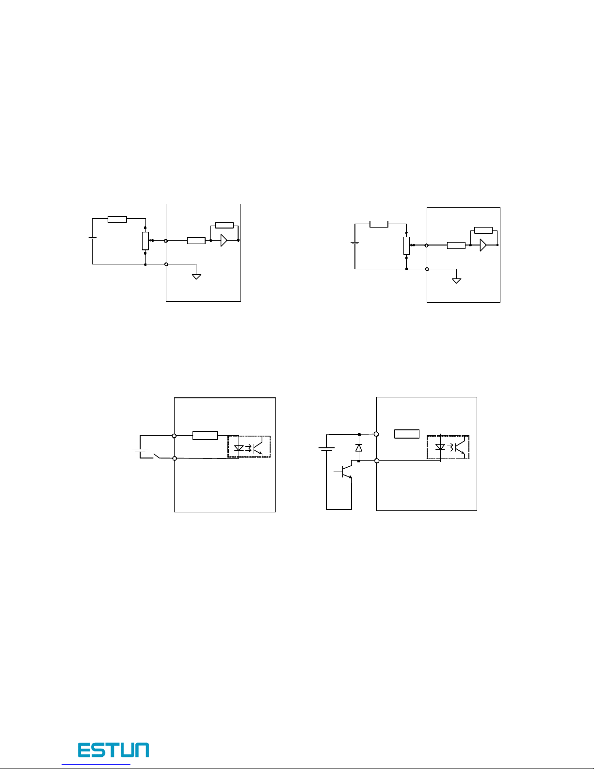
- 27 -
3.2.4 Interface Circuit
This section shows examples of servodrive I/O signal connection to the host controller.
■
Interface
Interface
Interface
Interface for
for
for
for Analog
Analog
Analog
Analog Reference
Reference
Reference
Reference Input
Input
Input
Input Circuit
Circuit
Circuit
Circuit
Analog signals are either speed or torque reference signals at about 40k Ω impedance, and the
maximum allowable voltages for input signals is ± 10V.
Reference speed input Reference torque input
■
Interface
Interface
Interface
Interface for
for
for
for sequence
sequence
sequence
sequence input
input
input
input circuit
circuit
circuit
circuit
The sequence input circuit interface connects thro ugh a relay or open-collector transistor circuit.Select a
low-current relay otherwise a faulty contact will result.
■
Interface
Interface
Interface
Interface for
for
for
for line
line
line
line driver
driver
driver
driver output
output
output
output circuit
circuit
circuit
circuit
The amount of two-phase (phase A and phase B) pulse output signals (PAO,/PAO,PBO,/PBO) and
z ero-point pulse signals(PCO,/PCO) are output via line-driver output circuits.Normally, the servodrive
uses this output circuit in speed control to comprise the pos ition control system at the host controller.
Connect the line-driver output circuit thro ugh a line receiver circuit at the host controller.
■
Interface
Interface
Interface
Interface for
for
for
for sequence
sequence
sequence
sequence output
output
output
output circuit
circuit
circuit
circuit
Photocoupler output circuits are used for Servo Alarm (ALM), Servo Ready(S-RDY), and other
sequence output signal circuits.Connect a photocoupler output circuit through a relay circuit.
10
V
470
Ω ( 1 / 2 W )
min
.
1
2
3
2 K Ω
V -
REF
AGND
About 40K Ω
0 V
Servodrive
10
V
470
Ω ( 1 / 2 W )
min
.
1
2
3
2 K Ω
T -
REF
AGND
About 40K Ω
0 V
Servodrive
Servodrive
Servodrive
Servodrive
Servodrive
3 . 3 K Ω
+24VIN
/ S -ON,
etc
.
DC24V
50
mA min
.
Servodrive
Servodrive
Servodrive
Servodrive
3 . 3 K Ω
+24VIN
/ S -ON,
etc
.
DC24V
50
mA min
.
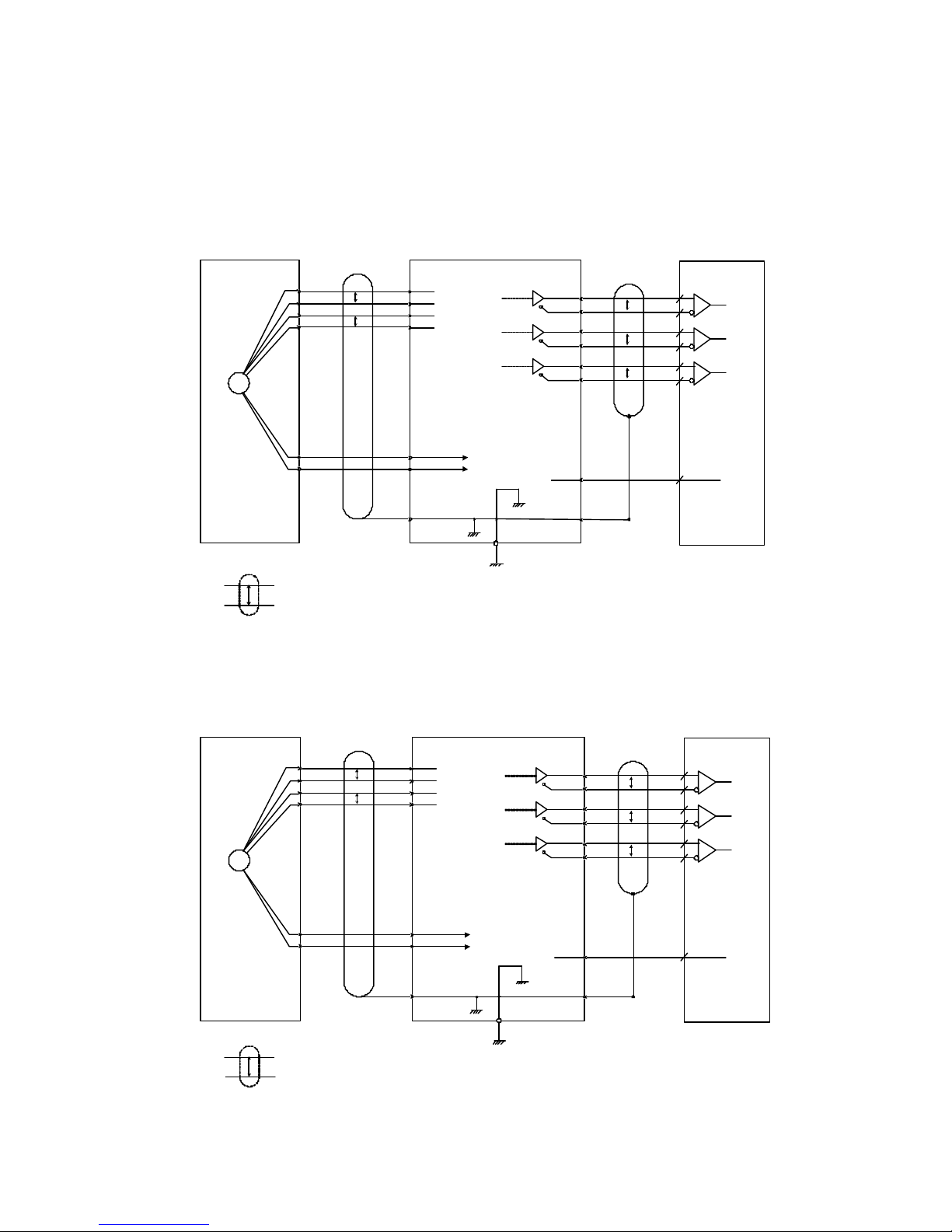
ProNet series AC servo system User’s manual V.1.08
- 28 -
3.3 Wiring Encoders
3.3.1 Connecting
an
Encoder(CN2)
Incremental/Absolute Encoders
Resolver
Incremental
Incremental
Incremental
Incremental /
/
/
/ Absolute Encoders
Absolute Encoders
Absolute Encoders
Absolute Encoders
Servodrive
Servodrive
Servodrive
Servodrive
PG
K
L
T
S
PS
/
PS
BAT
+
BAT
-
H
G
PAO
/
PAO
20
21
P
P
P
*
*
PG
5 V
PG
0 V
Connector shell
Connector shell
Connector shell
Connector shell
Connector shell
Connector shell
Connector shell
Connector shell
shielded wires
shielded wires
shielded wires
shielded wires
P
Represents multi
Represents multi
Represents multi
Represents multi -
-
-
- core twisted pair shielded wires
core twisted pair shielded wires
core twisted pair shielded wires
core twisted pair shielded wires .
.
.
.
*
Phase
- A
Output line driver
Output line driver
Output line driver
Output line driver
AM
AM
AM
AM
26
26
26
26
LS
LS
LS
LS
31
31
31
31
manufac tured
manufac tured
manufac tured
manufac tured
by TI or the equivalent
by TI or the equivalent
by TI or the equivalent
by TI or the equivalent
.
.
.
.
CN
1
CN
2
7
8
17
18
9
19
FG
Applicable line
Applicable line
Applicable line
Applicable line -
-
-
-
receive r SN
receive r SN
receive r SN
receive r SN
75175
75175
75175
75175
manufac tured by TI
manufac tured by TI
manufac tured by TI
manufac tured by TI
or the equivalent
or the equivalent
or the equivalent
or the equivalent .
.
.
.
PBO
/
PBO
22
23
P
Phase
- B
PCO
/
PCO2425
P
Phase
- C
0 V
DGND
0 V
50
(
Shell
Shell
Shell
Shell
)
Note: There are no BAT+ and BAT
- signals in incremental encoder .
Host controller
Host controller
Host controller
Host controller
Resolver
Resolver
Resolver
Resolver
Servodrive
Servodrive
Servodrive
Servodrive
PG
K
L
T
S
SIN
+
SIN
-
COS
+
COS
-
H
G
PAO
/
PAO2021
P
P
P
*
*
R 1
R 2
Connect shell
Connect shell
Connect shell
Connect shell
Connector shell
Connector shell
Connector shell
Connector shell
shielded wires
shielded wires
shielded wires
shielded wires
P Represents multi
Represents multi
Represents multi
Represents multi -
-
-
- core twisted pair shielded wires
core twisted pair shielded wires
core twisted pair shielded wires
core twisted pair shielded wires .
.
.
.*
Phase
- A
Output line
Output line
Output line
Output line
-
-
-
-
driver
driver
driver
driver
AM
AM
AM
AM
26
26
26
26
LS
LS
LS
LS
31
31
31
31
manufac tured by TI
manufac tured by TI
manufac tured by TI
manufac tured by TI
or equivalent
or equivalent
or equivalent
or equivalent .
.
.
.
CN
1
CN
2
7
8
17
18
9
19
FG
Applicable line
Applicable line
Applicable line
Applicable line -
-
-
-
receive r SN
receive r SN
receive r SN
receive r SN
75175
75175
75175
75175
manufac tured by
manufac tured by
manufac tured by
manufac tured by
TI or equivalent
TI or equivalent
TI or equivalent
TI or equivalent .
.
.
.
PBO
/
PBO2223
P
Phase
- B
PCO
/
PCO2425
P
Phase
- C
0 V
DGND
0 V
50
( Shell
Shell
Shell
Shell )
Host controller
Host controller
Host controller
Host controller
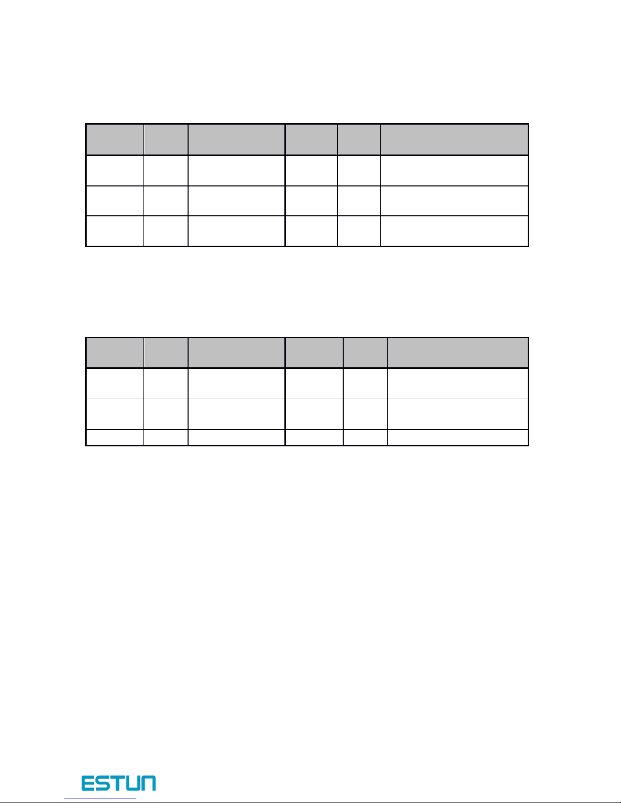
- 29 -
3.3.2 Encoder Connector(CN2) Terminal Layout
Incremental/ Absolute Encoder
Resolver
Term inal
Term inal
Term inal
Term inal
No.
No.
No.
No.
Name
Name
Name
Name
Function
Function
Function
Function
Term inal
Term inal
Term inal
Term inal
No.
No.
No.
No.
Name
Name
Name
Name
Function
Function
Function
Function
7
PS
PG serial signal
input
17
BAT+
Battery(+)
(For an absolute encoder)
8
/PS
PG serial signal
input
18
BAT-
Battery(-)
(For an absolute encoder)
9
PG5V
PG power supply
+5V
19
GND
PG power supply 0V
Term inal
Term inal
Term inal
Term inal
No.
No.
No.
No.
Name
Name
Name
Name
Function
Function
Function
Function
Term inal
Term inal
Term inal
Term inal
No.
No.
No.
No.
Name
Name
Name
Name
Function
Function
Function
Function
7
SIN+
Differential Sine
Signal
17
COS+
Differential Cosine Signal
8
SIN-
Differential Sine
Signal
18
COS-
Differential Cosine Signal
9R1Excitation signal
19R2Excitation signal
 Loading...