

Estun E21 Instruction Book
E21 Instruction Book
Document Version: V1.03
Software Version: V1.11
Single-Step
Description
1. The default page is SINGLE; also, you can press P key several
times, switching to the SIN GLE page.
2. Press Arrow Keys to select the parameter you want to program.
3. Press Numeric Keys to program a desired value.
4. Press Enter Key to complete the setting.
5. Follow the above meth ods to program the others parameters.
6. After finishing the program , press Startup Key to run the device.
Parameter
Page
Parameter
Description
Single-Step
X
Actual position of the back gauge
Y
Actual position of the slider
XP
Programmed position of the back gauge
YP
Programmed position of the slider
DX
Retract distanc e of the back gauge
HT
Hold time of punch at the bending point
DLY
Delay time in seconds f or X-axis retracting
PP
Preset work pieces
CP
■PP>0, indicat es the residual workpieces
■PP=0, indicat es the finished workpieces
Example
<INFO> There is one batch of mater ials, the requirement of bend ing are as
following: 10 pieces, bend depth is 100.00mm, back gauge position
is 80.00mm, the retract distance is 5.00mm, the delay time for
retracting is 2 seconds, and the hold ing time is 3 sec onds.
<PROCEDURE>
1. Program the parameter XP to 80.
2. Press Enter Key, movin g the cursor to the next parameter; and
program the parameter YP to 100.00
3. Press Enter Key, movin g the cursor to the next parameter, and
program the parameter DX to 5.00
4. Press Enter Key, movin g the cursor to the next parameter, and
program the parameter HT to 3.00
5. Press Enter Key, movin g the cursor to the next parameter, and
program the parameter DLY to 2.00
6. Press Enter Key, movin g the cursor to the next parameter, and
program the parameter PP to 10
7. Press Enter Key to finish the program.
8. Press Startup Key to run the device.
Example
<INFO> T here are 50 pieces of material, which are bent as following:
The first bending: bend dep th is 85.00mm, back gauge position is
50.00mm, retrac t distance is 5.00mm
The second bending: bend depth is 85.00mm, back gauge position
is 100.00mm, retract distance is 5.00mm
The third bending: bend dep th is 85.00mm, back gau ge position is
300.00mm, retract distance is 5.00mm
Put the aboveprogram into Program-No 1.
<PROCEDURE>
1. Press P key several times, switching to the PROGRAMS page
2. Select 1 and press Enter Key to enter the General Parameters
page; and program the parameter ST to 3
3. Press Enter Key, moving the cursor to the next parameter; and
program the parameter PP to 50
4. Press Enter Key, moving the cursor to the next parameter; and
program parameter DLY to 2.00
5. Press Enter Key, moving the cursor to the next parameter; and
program the parameter HT to 3.00
6. Press Enter Key and <Arrow Right> Key to enter the Step 1
Setting page; and program the parameter XPto 50.00
7. Press Enter Key, moving the cursor to the next parameter; and
program the parameter YP to 85.00
8. Press Enter Key, moving the cursor to the next parameter; and
program the parameter DX to 5.00
9. Press Enter Key, moving the cursor to the next parameter; and
program the parameter RP to 1
10. Press Enter Key and <Arrow Right> Key to enter the next step
parameters setting page; follow the above methods toprogram the
parameters of Step 2 and Step 3
11. After finishing the program, press P key to back the Total
Parameters page or the Step 1 page
12. Press Startup Key to run the device.
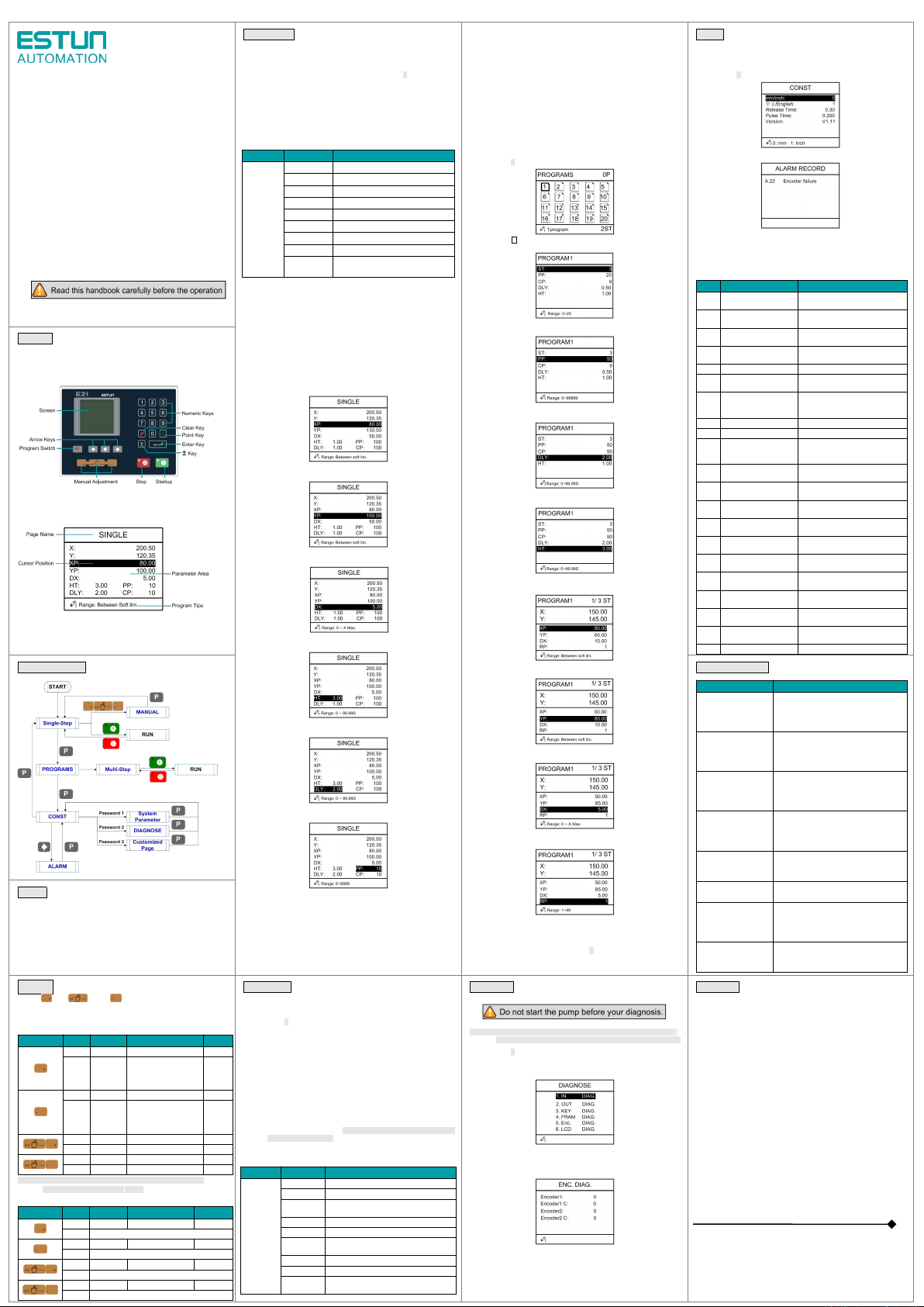
Alarm
Procedure
1. Press P key several times, switching to the CONST page.
2. Press <arrow right> key to enter the ALARM RECORD page.
Alarm List
The page can show the latest 6alarm info.And, thefollowin g table lists
all the alarm info.
No.
Name
Resolver
A.02
XPos < minimum
Move X-axis forwards in Manual
Movement.
A.03
XPos > maximum
Move X-axis backwards in Manual
Movement.
A.04
YPos < minimum
Move Y-axis forwards in Manual
Movement.
A.05
YPos > maximum
Move Y-axis backwards in Manual
Movement.
A.06
X out oflmt.
Re-teach the position of X-axis.
A.11
Count reached
shut-down
Rerun, the alarm is c leared
automatically.
A.12
Beam is not on upper
dead point
Step on the Foot Up Switch, moving
the slider tothe TDC, and the alarm
will be cleared automatically.
A.13
X Un-teachI n
Re-teach the position of X-axis.
A.14
Y Un-teachI n
Re-teach the position of Y-axis.
A.21
Oil pump not started
Check whether the pump signal is
connected, an d check whether the
pump switch is on.
A.22
Encoder failure
Check whether the encoder wiring is
normal.
A.25
Drive mode err
Reprogram the Drive Mode for
X-axis and Y-axis.
A.26
X Stop Err
Check whether the back gauge
motor is run normally.
A.27
Y Stop Err
Check whether the slider motor is
run normally.
A.28
X V2 Err
Check whether the back gauge
motor is run normally.
A.29
X V3 Err
Check whether the back gauge
motor is run normally.
A.30
Y V2 Err
Check whether the slider motor is
run normally.
A.31
Y V3 Err
Check whether the slider motor is
run normally.
A.32
XPos < 0
Move X-axis forwards to the setting
range in Manual Movement.
A.33
YPos < 0
Move Y-axis forwards to the setting
range in Manual Movement.
A.41
Parameter storage error
Back to factory for repairing
Display
PanelPage
Operation Flow
Troubleshooting
Fault
Trouble shooting
The screen don’t display
when power on.
■The terminal ofpower supply wiring is error.
Follow the nameplate to rewire.
■The source voltage is too low.
■The connec tor is not connected well.
The back gauge motor
doesn’t run when X-axis
is operated, butthe
slider motor runs.
The wires of these two motor are in reverse,
please rewire.
The motor doesn’t run
when operating .
■Check whet her the machine is impede d, or
whether the slider is back to TDC
■Check whet her the motor wire is connected
well.
The motor can’t mutually
convert from high to low
■Check whet her the signal is in effect, or
whether f requency c onverter is normal.
■Check whet her parameter Mute Dis. is
programmed correctly.
The step can’t be
changed in Multi-Step
mode.
Check the START terminal is connected to
+24V when the slider is on TDC.
The counter doesn’t
work in Multi-Step mode.
Check the START terminal is connected to
+24V when the slider is on TDC.
Lose control ofthe
system
■Check whet her the encoder cable is
connected w ell.
■Check whet her the motor direction wiring
(X+, X-, Y+,Y-) is correct.
The actual position of
X-axis or Y-axis is
unchanged or unshown.
Check whether the encoder cable is
connected well or correctly.
Notice
W hen the REDindicat or light is on, you can program the parameters.
Only when the page is onS INGLE, Total Parameters page or the Step 1
page, you can press Startu p Key to run the device.
Press StopKey to stop themachine, and the device backsto theprevious
page.
When the page
displays
the alarm info,you should resolve the problem
with some effective measures (see Alarm List). The device will be reset
by the self-diagnosis function.
Manual
Press key, key or key to enterthe MANUAL page.
Press Arrow Keys to select the axis you w ant to adjust, and follow the
below table to operate.
The drive mode of the corresponding axis ismotor .
Press Key
Status
Direction
Duration
Speed
STOP
increasing
Press Time
Slow
RUN
increasing
■Press Time (PressTime <
Pulse Time)
■Pulse Time (PressTime >
Pulse Time)
Slow
STOP
decreasing
Press time
Slow
RUN
decreasing
■Press Time (PressTime <
Pulse Time)
■Pulse Time (PressTime >
Pulse Time)
Slow
STOP
increasing
Press time
Slow
RUN
increasing
Press time
Slow
STOP
decreasing
Press time
Slow
RUN
decreasing
Press time
Slow
<Note>: W hen the systemis on run s tatus, the operation of manu al
movement is just valid f or the X-axis.
The drive mode of the corresponding axis isfrequ ency converte r.
Press Key
Status
Direction
Duration
Speed
STOP
increasing
Press Time
Slow
RUN
Unable
STOP
decreasing
Press Time
Slow
RUN
Unable
STOP
increasing
Press Time
Fast
RUN
Unable
STOP
decreasing
Press Time
Fast
RUN
Unable
Multi-Step
Description
1. Press P key several times, switching to the PROGRAMS page.
2. Press Arrow Keys to select a desired No, or you can press
Numeric Keys to input a desired N o, and then press Enter Key to
enter the General Parameters page.
4. Press Arrow Keys to select the parameter you want to program.
5. Press Numeric Keys to program a desired value.
6. Press Enter Key to complete the setting.
7. Follow the above meth ods to program the others general
parameters.
8. After finishing the program , press <arrow right> key to enter the
Step Setting page.
9. Follow the above meth ods to program the others step parameters.
10. Press <arrow right> or <arrow left> key to enter the others Step
Setting page, and program the desired parameters.
11. After finishingthe program,you should back to the Total Parameters
page or theStep 1 page, and press Startup Key to run the device.
Parameter
Page
Parameter
Description
Multi-Step
ST
The number of steps
PP
Preset workpieces
CP
■PP>0, indicat es the residual workpieces
■PP=0, indicat es the finished workpieces
DLY
Delay time in seconds f or X-axis retracting
HT
Hold time of punch at the bending point
XP
Programmed position of the back gauge in
the step
YP
Programmed posi tion of the slider in thestep
DX
Retract distanc e of the back gauge
RP
The number of times a step is repeated
before the next step is executed
Diagnosis
<NOTE> The following is only described how todiagnos e the encoder, and
for the othersdiagn osis, just according to the page tips to operate.
1. Press P key several times, switching to the CONST page.
2. Press Numeric Keys to input the password 5656, and press Enter
Key to enter the DIAGNOS E page.
3. Select 5. Enc. DIAG. or press Numeric Key 5 directly, and then
press Enter Key to enter the ENC. DIAG. page.
4. Rotate the encoders of X-axis and Y-axis, the page displays the
pulse changing. The corresponding C-pulse will jumpbetw een 0
and 1, whichind icates the encoder port is normal.
Reference
< E21 Installation Manual >
< E21 Operation Manual >
ESTUN AUTOMATION CO., LTD
Add: 155 Jiangjun Road, Jiangning Development Zone,
Nanjing 211106, P.R.China
TEL: 025-52785866
FAX: 025-52785992
WEB: www.estun.com
Email: info@estun.com
4
6
1
2
3
579
8

 Loading...