

Estia HWS-2101CSHM3-E, HWS-1501CSHM3-E, HWS-3001CSHM3-E Installation Manual

AIR TO WATER HEAT PUMP SYSTEM
Installation manual
HOT WATER CYLINDER
INDIRECT HEATING METHOD
CLOSED OUTLET (UNVENTED)
150 litre HWS-1501CSHM3-E
210 litre HWS-2101CSHM3-E
300 litre HWS-3001CSHM3-E
AIR TO WATER HEAT PUMP SYSTEM
INSTALLATIONAND SERVICE MANUAL 3
EN
SYSTÈMEDE POMPE À CHALEUR AIR-EAU
MANUELD'INSTALLATION ET DE RÉPARATION 14
FR
LUFT-WASSER-WARMERPUMPENSYSTEM
INSTALLATIONS - UND WARTUNGSANLEITUNG 26
DE
SYSTÉM TEPELNÉHO ČERPADLA(VZDUCH - VODA)
SERVISNÍA MONTÁŽNÍ MANUÁL 38
CZ
CR
LEVEGŐ-VÍZ HŐSZIVATTYÚ RENDSZER
FELSZERELÉSI ÉS SZERVIZELÉSI KÉZIKÖN 60
HU
ΣΥΣΤΗΜΑΑΝΤΛΙΑΣ ΘΕΡΜΑΝΣΗΣ ΑΕΡΑ - ΝΕΡΟΥ
ΕΓΧΕΙΡΙ∆ΙΟ ΕΓΚΑΤΑΣΤΑΣΗΣ ΚΑΙ ΣΥΝΤΗΡΗΣΗΣ 72
GR
LUFT/VATTEN-VÄRMEPUMPSSYSTEM
INSTALLATIONS- OCH SERVICEMANUAL 84
SV
LUFT-TIL-VANN VARMEPUMPESYSTEM
INSTALLASJONS- OG VEDLIKEHOLDSHÅNDBOK 95
NO
SYSTÉMTEPELNÉHO ČERPADLA VZDUCH-VODA
NÁVOD NA INŠTALÁCIU A OBSLUHU 106
SK
SISTEM TOPLOTNE ČRPALKE ZRAK–VODA
PRIROČNIK ZA MONTAŽO IN VZDRŽEVANJE 118
SL
SUSTAV S TOPLINSKOM CRPKOM ZRAK-VODA
PRIRUČNIK ZA UGRADNJUI SERVISIRANJE 49

AIR TO WATER HEAT PUMP SYSTEM INSTALLATION AND SERVICE MANUAL
3
EN
AIR TO WATER HEAT PUMP SYSTEM
HOT WATER CYLINDER
INDIRECT HEATING METHOD
CLOSED OUTLET (UNVENTED)
INSTALLATION AND SERVICE MANUAL
IMPORTANT
PLEASE READ AND UNDERSTAND THESE INSTRUCTIONS BEFORE
INSTALLING THE WATER CYLINDER. INCORRECT INSTALLATION MAY
INVALIDATE GUARANTEE. THE WATER CYLINDER MUST BE INSTALLED
BY A QUALIFIED INSTALLER IN ACCORDANCE WITH LOCAL PLUMBING,
BUILDING AND ELECTRICAL REGULATIONS. PLEASE LEAVE THIS MANUAL
WITH THE UNIT FOR FUTURE REFERENCE.
TECHNICAL SPECIFICATIONS
Rated pressure 1.0 MPa (10 bar)
Test pressure (hydraulic) 1.5 MPa (15 bar)
Minimum recommended supply pressure 0.1 MPa (1 bar)
Max. primary circuit working pressure 0.35 MPa (3.5 bar)
Electrical rating (cylinder heater) 2.75kW @ 230V~
Weight (full) 150 litre indirect 181 kg
210 litre indirect 251 kg
300 litre indirect 360 kg
COMPONENTS SUPPLIED
• Water cylinder incorporating electric cylinder heater and thermal controls.
• Safety Group incorporating a Pressure Relief Valve, Check (Non-return) Valve
and Isolating Valve.
• Compression nuts and olives.
• Cylinder heater key spanner.

France
Carrier S.A. Route de Thil
BP 49 01122 Montiuel
Cedex France
Germany / Deutchsland
Carrier GmbH & Co. KG
Edisonstrasse 2 85716
Unterschleissheim
Czech Republic / Česko
AIRCOND, Klimaanlagen
Handelsgesellshcaft m.b.H
Petersgasse 45, A-8010
Graz Austria
Croatia / Hrvatska
AIRCOND, Klimaanlagen
Handelsgesellshcaft m.b.H
Petersgasse 45, A-8010
Graz Austria
Austria / Österreich
AIRCOND, Klimaanlagen
Handelsgesellshcaft m.b.H
Petersgasse 45, A-8010
Graz Austria
Hungary / Magyar
AIRCOND, Klimaanlagen
Handelsgesellshcaft m.b.H
Petersgasse 45, A-8010
Graz Austria
Greece / Ελλάδα
Carrier Hellas
Aircondilioning S.A.- 4g
Andersen street-11525
Athens Greece
Sweden / Sverige
Carrier AB - P.O.BOX 8946Arods Industrivag 32. S-402
73 Gothenburg Sweden
Norway / Norge
Carrier AB - P.O.BOX 8946Arods Industrivag 32. S-402
73 Gothenburg Sweden
Slovakia / Slovensko
AIRCOND, Klimaanlagen
Handelsgesellshcaft m.b.H
Petersgasse 45, A-8010
Graz Austria
Slovenia / Slovenija
AIRCOND, Klimaanlagen
Handelsgesellshcaft m.b.H
Petersgasse 45, A-8010
Graz Austria

AIR TO WATER HEAT PUMP SYSTEM INSTALLATION AND SERVICE MANUAL
4
EN
1.0 IMPORTANT INSTALLATION POINTS
1.1 The unit, for use with the ESTIA air to water heat pump system, is a purpose
designed unvented water cylinder.
1.2 The water cylinder MUST be fitted with a Pressure Relief Valve that complies
with your local Plumbing and Building Regulations. FAILURE TO PROVIDE
ADEQUATE PRESSURE RELIEF WILL INVALIDATE ANY GUARANTEE
AND LEAD TO A DANGEROUS INSTALLATION.
1.3 Where the inlet pressure exceeds 0.6 MPa (6 bar) a Pressure Reducing Valve
(set at max. 0.5 MPa (5 bar)) should be fitted to the inlet supply to the water
cylinder. This MUST NOT be fitted between the Pressure Relief Valve and the water
cylinder.
1.4 A Check (non-return) Valve should be fitted to the inlet supply to the water cylinder.
This MUST NOT be fitted between the Pressure Relief Valve and the water cylinder.
1.5 This appliance is not intended for use by persons (including children) with
reduced physical, sensory or mental capabilities, or lack of experience or
knowledge, unless they have been given supervision or instruction concerning
use of the appliance by a person responsible for their safety. Children should be
supervised to ensure that they do not play with the appliance.
2.0 INSTALLATION – GENERAL REQUIREMENTS
2.1 National Wiring Regulations may contain restrictions concerning the installation
of these units in certain areas, eg. Bathrooms.
2.2 The unit MUST be installed vertically.
2.3 The unit must be positioned on a level surface.
2.4 Enough space should be left around the unit for pipe connections and for access
to controls and any safety valves fitted. Refer to Diagram 1 and the Dimensions
Table to determine a suitable position for the water cylinder.
2.5 NOTE: Ensure the floor can support the full weight of the unit (see TECHNICAL
SPECIFICATIONS).
2.6 DO NOT install where the unit may freeze.
2.7 The mains water supply to the property will be supplying both the hot and cold
water requirements simultaneously. It is recommended that the maximum water
demand is assessed and the water supply checked to ensure this demand can
be satisfactorily met.
NOTE: a high mains water pressure will not always guarantee high flow rates.
We suggest the minimum supply requirements should be 0.1 MPa (1.0 bar)
pressure and 20 litres per minute flowrate. However, at these values outlet flow
rates may be poor if several outlets are used simultaneously. The higher the
available pressure and flow rate the better the system performance.
2.8 LIMITATIONS:
The water cylinder should not be used in association with any of the following:
• Situations where maintenance is likely to be neglected or safety devices
tampered with.
AIR TO WATER HEAT PUMP SYSTEM INSTALLATION AND SERVICE MANUAL
5
EN
• Water supplies that have either inadequate pressure or where the supply
may be intermittent.
• Situations where it is not possible to safely pipe away any discharge from the
safety valves.
• Areas where the water supply consistently contains a high proportion of
solids or suspended matter unless adequate filtration can be ensured on the
inlet water supply.
3.0 INSTALLATION – PLUMBING
3.1 Refer to section IMPORTANT INSTALLATION POINTS. Plumb in valves in the
sequence shown in Diagram 2. Ensure the valves are installed in the correct
orientation by reference to the direction of flow arrows marked on them.
The water cylinder MUST be fitted with a Pressure Relief Valve that complies
with your local Plumbing and Building Regulations. (Safety Group supplied).
FAILURE TO PROVIDE ADEQUATE PRESSURE RELIEF WILL INVALIDATE
ANY GUARANTEE AND LEAD TO A DANGEROUS INSTALLATION. Any
discharge pipe connected to the Pressure Relief device must be installed in a
continuously downward direction in a frost free environment.
3.2 The water connections on the unit accept direct connection of 22mm outside
diameter pipe; nuts and olives are supplied for this purpose. The thread on the
connections is G3/4 to enable the use of G3/4 female connections to be used if
required. DO NOT use zinc plated water pipes. When steel pipes are used the
pipe should be insulated from the stainless steel vessel by using di-electric
couplings.
3.3 The sanitary water INLET is marked BLUE, the OUTLET is marked RED.
Several hot outlets can be served, however, individual site demands should be
considered when choosing capacity and the number of outlets to be served.
3.4 It is recommended that an isolating valve is fitted on the cold water supply to
the water cylinder.
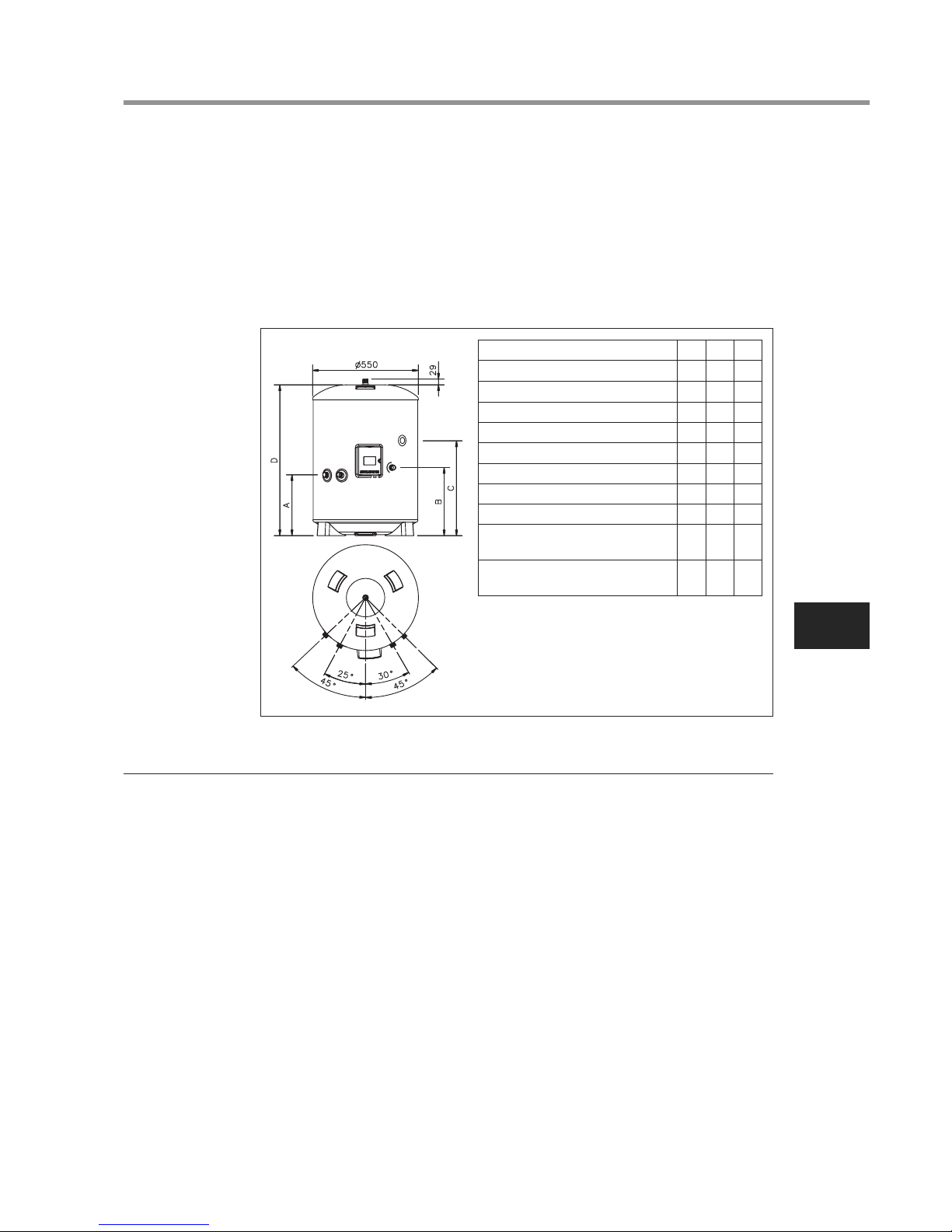
Diagram 1
NOMINAL CAPACITY(litres)
A (mm)
B (mm)
C (mm)
D (mm)
SURFACE AREA (sq.m)
HOT WATER OUTPUTAT60ºC (litres)
MIXEDHOTWATER OUTPUT AT 40ºC (litres)
HEAT LOSS(kWh/24h)
HEATING TIME 15ºC TO 60ºC- USING ELECTRIC
CYLINDER HEATER ONLY(mins)
CAPACITY HEATED USING ELECTRIC
CYLINDER HEATER ONLY(litres)
150 210 300
315 315 315
354 354 354
800 1184 1474
1090 1474 2040
0.65 0.79 0.79
102 163 254
243 329.5 476
1.45 1.91 2.52
123 188 262
102 163 254
 Loading...