

Estia HWS-1501CSHM3-E, HWS-2101CSHM3-E, HWS-3001CSHM3-E Installation And Service Manual
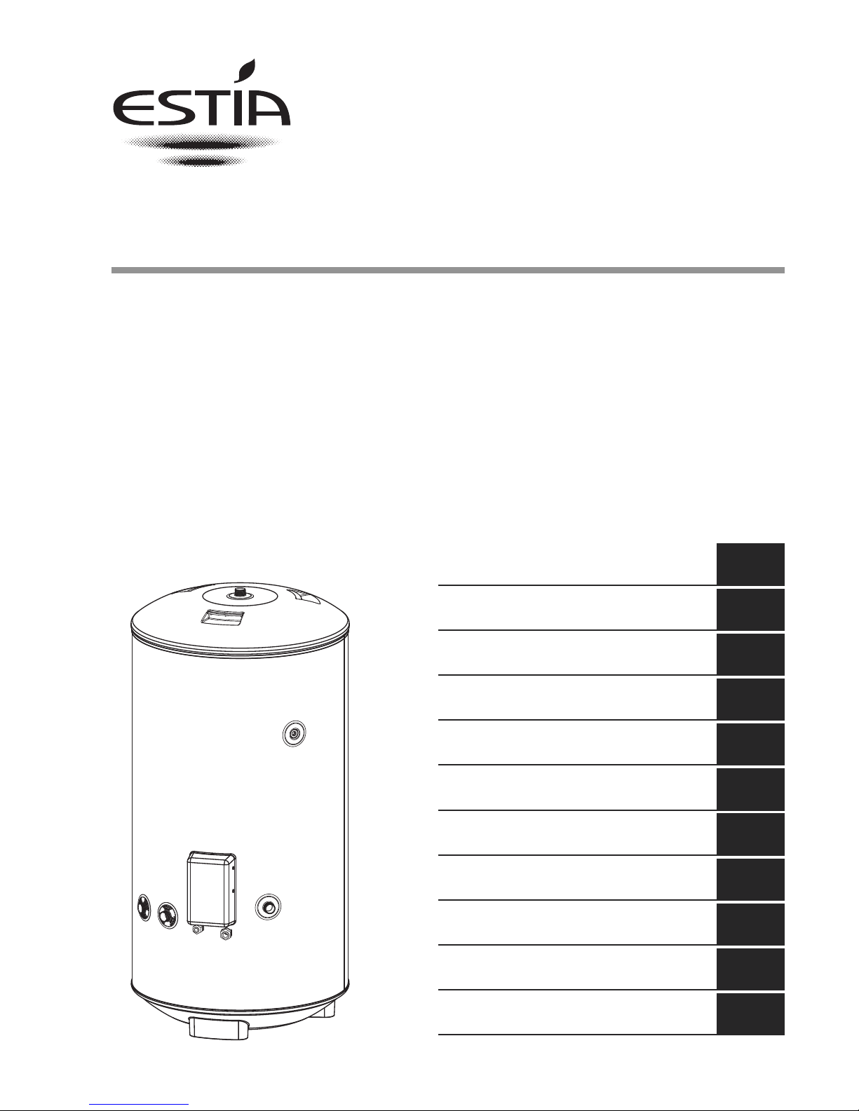
AIR TO WATER HEAT PUMP SYSTEM
Installation manual
HOT WATER CYLINDER
INDIRECT HEATING METHOD
CLOSED OUTLET (UNVENTED)
150 litre HWS-1501CSHM3-E
210 litre HWS-2101CSHM3-E
300 litre HWS-3001CSHM3-E
AIR TO WATER HEAT PUMP SYSTEM
INSTALLATIONAND SERVICE MANUAL 3
EN
SYSTÈMEDE POMPE À CHALEUR AIR-EAU
MANUELD'INSTALLATION ET DE RÉPARATION 14
FR
LUFT-WASSER-WARMERPUMPENSYSTEM
INSTALLATIONS - UND WARTUNGSANLEITUNG 26
DE
SYSTÉM TEPELNÉHO ČERPADLA(VZDUCH - VODA)
SERVISNÍA MONTÁŽNÍ MANUÁL 38
CZ
CR
LEVEGŐ-VÍZ HŐSZIVATTYÚ RENDSZER
FELSZERELÉSI ÉS SZERVIZELÉSI KÉZIKÖN 60
HU
ΣΥΣΤΗΜΑΑΝΤΛΙΑΣ ΘΕΡΜΑΝΣΗΣ ΑΕΡΑ - ΝΕΡΟΥ
ΕΓΧΕΙΡΙ∆ΙΟ ΕΓΚΑΤΑΣΤΑΣΗΣ ΚΑΙ ΣΥΝΤΗΡΗΣΗΣ 72
GR
LUFT/VATTEN-VÄRMEPUMPSSYSTEM
INSTALLATIONS- OCH SERVICEMANUAL 84
SV
LUFT-TIL-VANN VARMEPUMPESYSTEM
INSTALLASJONS- OG VEDLIKEHOLDSHÅNDBOK 95
NO
SYSTÉMTEPELNÉHO ČERPADLA VZDUCH-VODA
NÁVOD NA INŠTALÁCIU A OBSLUHU 106
SK
SISTEM TOPLOTNE ČRPALKE ZRAK–VODA
PRIROČNIK ZA MONTAŽO IN VZDRŽEVANJE 118
SL
SUSTAV S TOPLINSKOM CRPKOM ZRAK-VODA
PRIRUČNIK ZA UGRADNJUI SERVISIRANJE 49

AIR TO WATER HEAT PUMP SYSTEM INSTALLATION AND SERVICE MANUAL
3
EN
AIR TO WATER HEAT PUMP SYSTEM
HOT WATER CYLINDER
INDIRECT HEATING METHOD
CLOSED OUTLET (UNVENTED)
INSTALLATION AND SERVICE MANUAL
IMPORTANT
PLEASE READ AND UNDERSTAND THESE INSTRUCTIONS BEFORE
INSTALLING THE WATER CYLINDER. INCORRECT INSTALLATION MAY
INVALIDATE GUARANTEE. THE WATER CYLINDER MUST BE INSTALLED
BY A QUALIFIED INSTALLER IN ACCORDANCE WITH LOCAL PLUMBING,
BUILDING AND ELECTRICAL REGULATIONS. PLEASE LEAVE THIS MANUAL
WITH THE UNIT FOR FUTURE REFERENCE.
TECHNICAL SPECIFICATIONS
Rated pressure 1.0 MPa (10 bar)
Test pressure (hydraulic) 1.5 MPa (15 bar)
Minimum recommended supply pressure 0.1 MPa (1 bar)
Max. primary circuit working pressure 0.35 MPa (3.5 bar)
Electrical rating (cylinder heater) 2.75kW @ 230V~
Weight (full) 150 litre indirect 181 kg
210 litre indirect 251 kg
300 litre indirect 360 kg
COMPONENTS SUPPLIED
• Water cylinder incorporating electric cylinder heater and thermal controls.
• Safety Group incorporating a Pressure Relief Valve, Check (Non-return) Valve
and Isolating Valve.
• Compression nuts and olives.
• Cylinder heater key spanner.

AIR TO WATER HEAT PUMP SYSTEM INSTALLATION AND SERVICE MANUAL
4
EN
1.0 IMPORTANT INSTALLATION POINTS
1.1 The unit, for use with the ESTIA air to water heat pump system, is a purpose
designed unvented water cylinder.
1.2 The water cylinder MUST be fitted with a Pressure Relief Valve that complies
with your local Plumbing and Building Regulations. FAILURE TO PROVIDE
ADEQUATE PRESSURE RELIEF WILL INVALIDATE ANY GUARANTEE
AND LEAD TO A DANGEROUS INSTALLATION.
1.3 Where the inlet pressure exceeds 0.6 MPa (6 bar) a Pressure Reducing Valve
(set at max. 0.5 MPa (5 bar)) should be fitted to the inlet supply to the water
cylinder. This MUST NOT be fitted between the Pressure Relief Valve and the water
cylinder.
1.4 A Check (non-return) Valve should be fitted to the inlet supply to the water cylinder.
This MUST NOT be fitted between the Pressure Relief Valve and the water cylinder.
1.5 This appliance is not intended for use by persons (including children) with
reduced physical, sensory or mental capabilities, or lack of experience or
knowledge, unless they have been given supervision or instruction concerning
use of the appliance by a person responsible for their safety. Children should be
supervised to ensure that they do not play with the appliance.
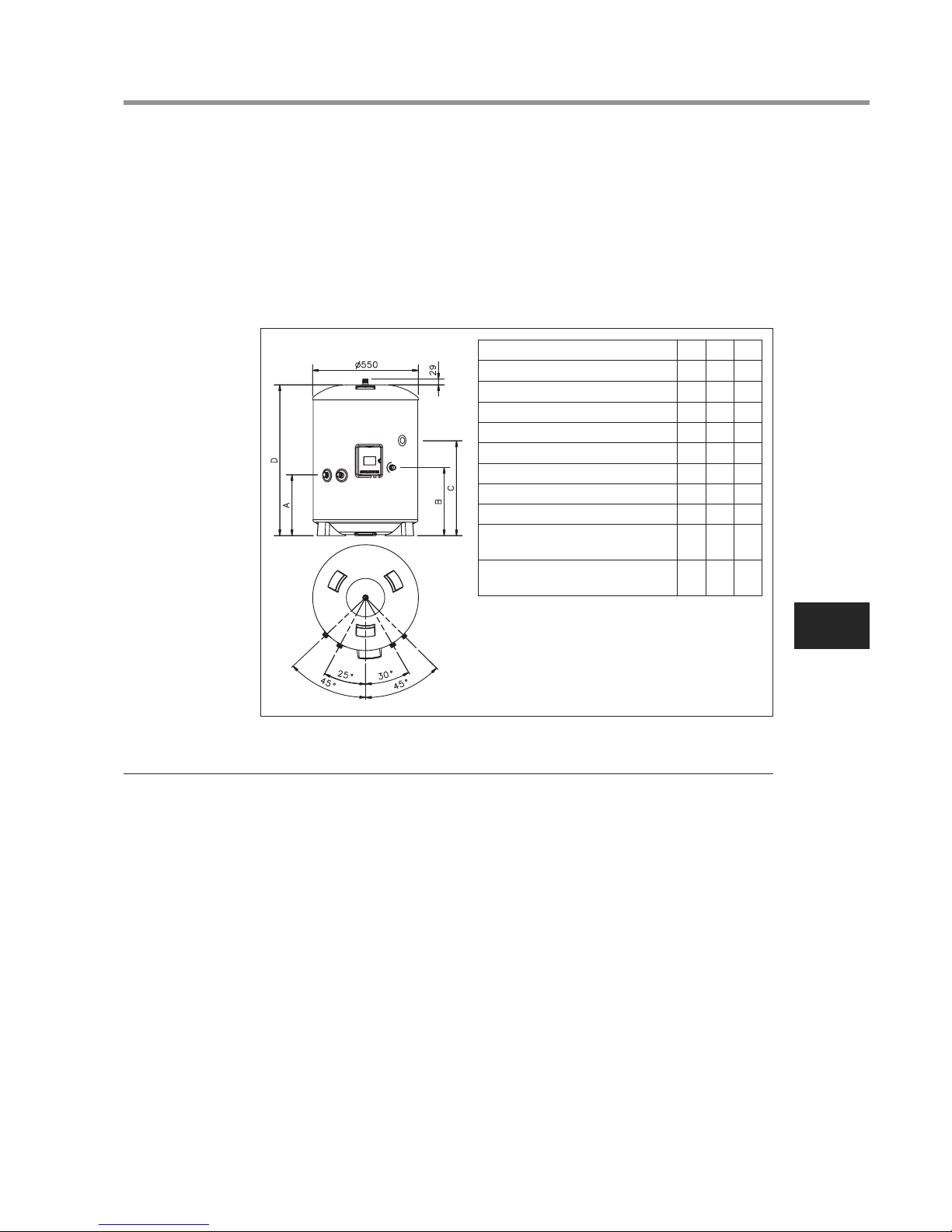
2.0 INSTALLATION – GENERAL REQUIREMENTS
2.1 National Wiring Regulations may contain restrictions concerning the installation
of these units in certain areas, eg. Bathrooms.
2.2 The unit MUST be installed vertically.
2.3 The unit must be positioned on a level surface.
2.4 Enough space should be left around the unit for pipe connections and for access
to controls and any safety valves fitted. Refer to Diagram 1 and the Dimensions
Table to determine a suitable position for the water cylinder.
2.5 NOTE: Ensure the floor can support the full weight of the unit (see TECHNICAL
SPECIFICATIONS).
2.6 DO NOT install where the unit may freeze.
2.7 The mains water supply to the property will be supplying both the hot and cold
water requirements simultaneously. It is recommended that the maximum water
demand is assessed and the water supply checked to ensure this demand can
be satisfactorily met.
NOTE: a high mains water pressure will not always guarantee high flow rates.
We suggest the minimum supply requirements should be 0.1 MPa (1.0 bar)
pressure and 20 litres per minute flowrate. However, at these values outlet flow
rates may be poor if several outlets are used simultaneously. The higher the
available pressure and flow rate the better the system performance.
2.8 LIMITATIONS:
The water cylinder should not be used in association with any of the following:
• Situations where maintenance is likely to be neglected or safety devices
tampered with.
AIR TO WATER HEAT PUMP SYSTEM INSTALLATION AND SERVICE MANUAL
5
EN
• Water supplies that have either inadequate pressure or where the supply
may be intermittent.
• Situations where it is not possible to safely pipe away any discharge from the
safety valves.
• Areas where the water supply consistently contains a high proportion of
solids or suspended matter unless adequate filtration can be ensured on the
inlet water supply.
3.0 INSTALLATION – PLUMBING
3.1 Refer to section IMPORTANT INSTALLATION POINTS. Plumb in valves in the
sequence shown in Diagram 2. Ensure the valves are installed in the correct
orientation by reference to the direction of flow arrows marked on them.
The water cylinder MUST be fitted with a Pressure Relief Valve that complies
with your local Plumbing and Building Regulations. (Safety Group supplied).
FAILURE TO PROVIDE ADEQUATE PRESSURE RELIEF WILL INVALIDATE
ANY GUARANTEE AND LEAD TO A DANGEROUS INSTALLATION. Any
discharge pipe connected to the Pressure Relief device must be installed in a
continuously downward direction in a frost free environment.
3.2 The water connections on the unit accept direct connection of 22mm outside
diameter pipe; nuts and olives are supplied for this purpose. The thread on the
connections is G3/4 to enable the use of G3/4 female connections to be used if
required. DO NOT use zinc plated water pipes. When steel pipes are used the
pipe should be insulated from the stainless steel vessel by using di-electric
couplings.
3.3 The sanitary water INLET is marked BLUE, the OUTLET is marked RED.
Several hot outlets can be served, however, individual site demands should be
considered when choosing capacity and the number of outlets to be served.
3.4 It is recommended that an isolating valve is fitted on the cold water supply to
the water cylinder.
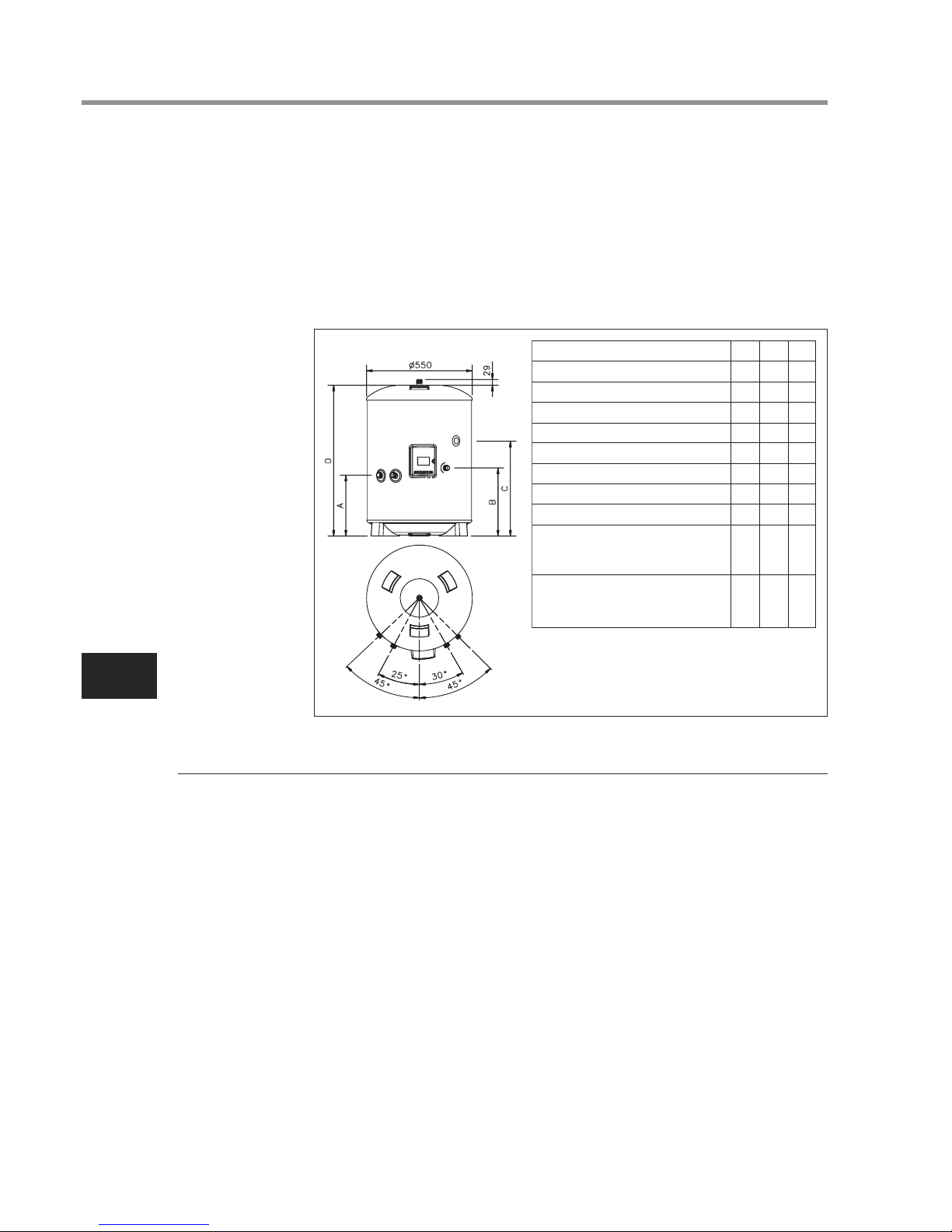
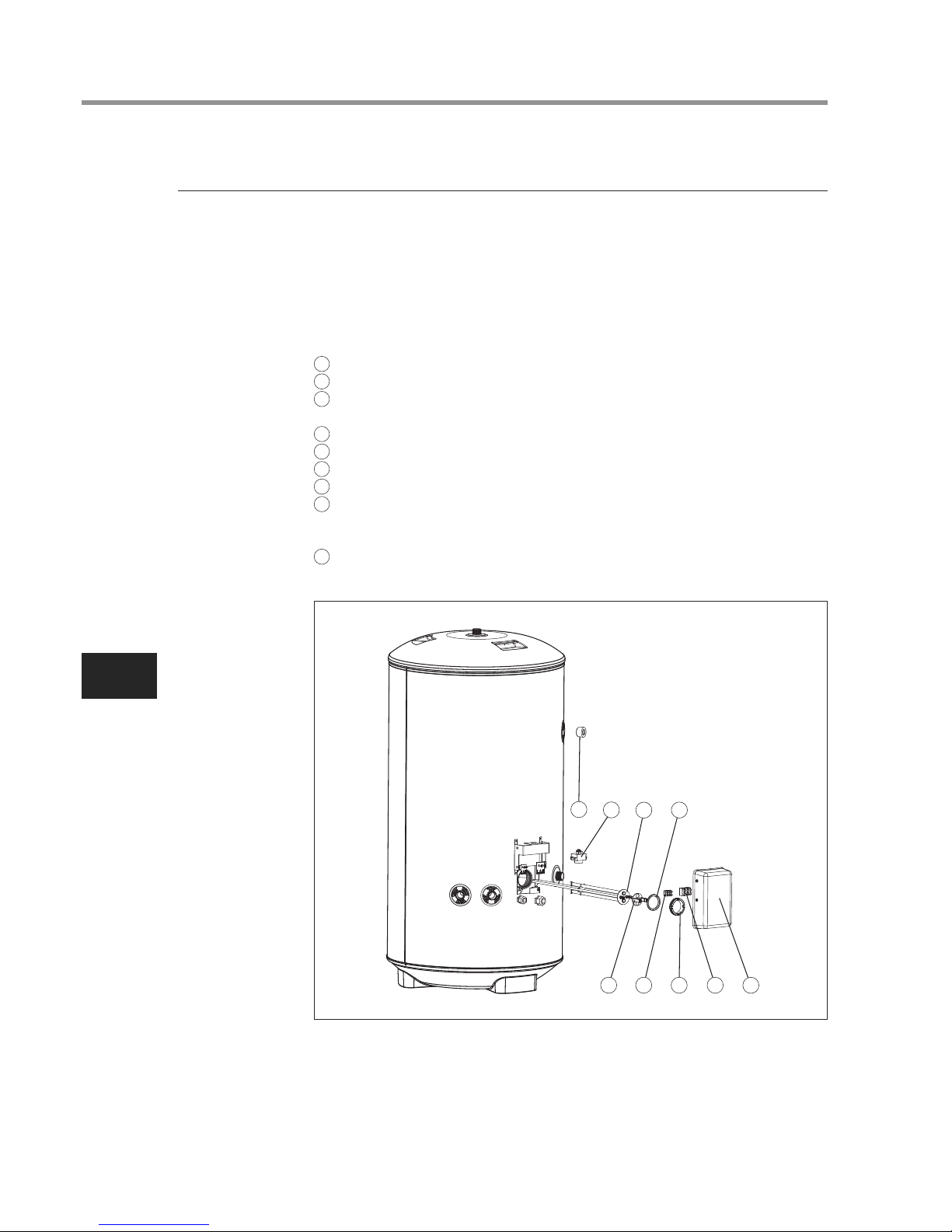
Diagram 1
NOMINAL CAPACITY (litres)
A (mm)
B (mm)
C (mm)
D (mm)
SURFACE AREA (sq.m)
HOT WATER OUTPUT AT 60ºC (litres)
MIXED HOT WATER OUTPUT AT 40ºC (litres)
HEAT LOSS (kWh/24h)
HEATING TIME 15ºC TO 60ºC - USING ELECTRIC
CYLINDER HEATER ONLY(mins)
CAPACITY HEATED USING ELECTRIC
CYLINDER HEATER ONLY(litres)
150 210 300
315 315 315
354 354 354
800 1184 1474
1090 1474 2040
0.65 0.79 0.79
102 163 254
243 329.5 476
1.45 1.91 2.52
123 188 262
102 163 254
AIR TO WATER HEAT PUMP SYSTEM INSTALLATION AND SERVICE MANUAL
6
EN
3.5 A drain cock must be fitted below the water cylinder in the inlet pipework. It must
be sited between the water cylinder and the Check Valve.
3.6 A sanitary circuit expansion vessel may be fitted to the cold water supply as
shown in Diagram 2 to prevent wastage of expanded water. The following sizes
are recommended:
150 litre 12 litre vessel
210 litre 18 litre vessel
300 litre 24 litre vessel
3.7 A re-circulation circuit can be installed on the sanitary water circuit. A connection
is provided for the re-circulation circuit return pipe (threaded G3/4 female).
3.8 The primary heating circuit MUST be connected via the Hydro Unit. Refer to the
Installation Instructions supplied with the Hydro Unit for full details.
4.0 ELECTRICAL REQUIREMENTS
4.1 The unit is supplied with a factory fitted cylinder heater complete with thermal
sensor and over-temperature cut-out. The cylinder heater is rated 2.75kW at
230V~.
4.2 The cylinder heater is located behind the white terminal cover on the front of the
unit. The cover is secured by 2 screws on each side of the cover and a threaded
domed nut on the front of the cover. ISOLATE THE ELECTRICAL SUPPLY
BEFORE REMOVING THE COVER.
4.3 The cylinder heater MUST be earthed.
4.4 All electrical wiring should be carried out by a competent electrician and be in
accordance with the latest national Wiring Regulations. The circuit must be
protected by a suitable fuse and double pole isolating switch with a contact
separation of at least 3mm in both poles.
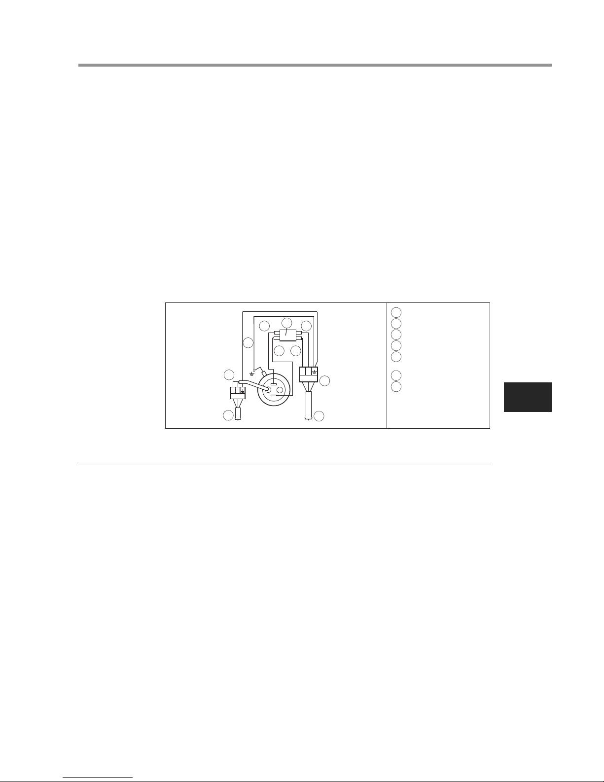
4.5 The cylinder heater should be wired in accordance with Diagram 3 and the Air to
Water Heat Pump Installation Manual. The supply cable must be via the Heat
Pump Controls Housing, direct connection to the mains electrical supply will
invalidate the guarantee and may result in a dangerous installation. The supply
cable must be routed through the right hand cable gland provided and the outer
sheath of the cable firmly secured by tightening the screw on the cable gland.
The recommended cable type is 2.5mm
2
3 core heat resistant sheathed.
4.6 The thermal sensor should be connected to the Heat Pump Controls Housing in
accordance with Diagram 3 and the Air to Water Heat Pump Installation Manual.
1
4
3
2
5
6
8
9
7
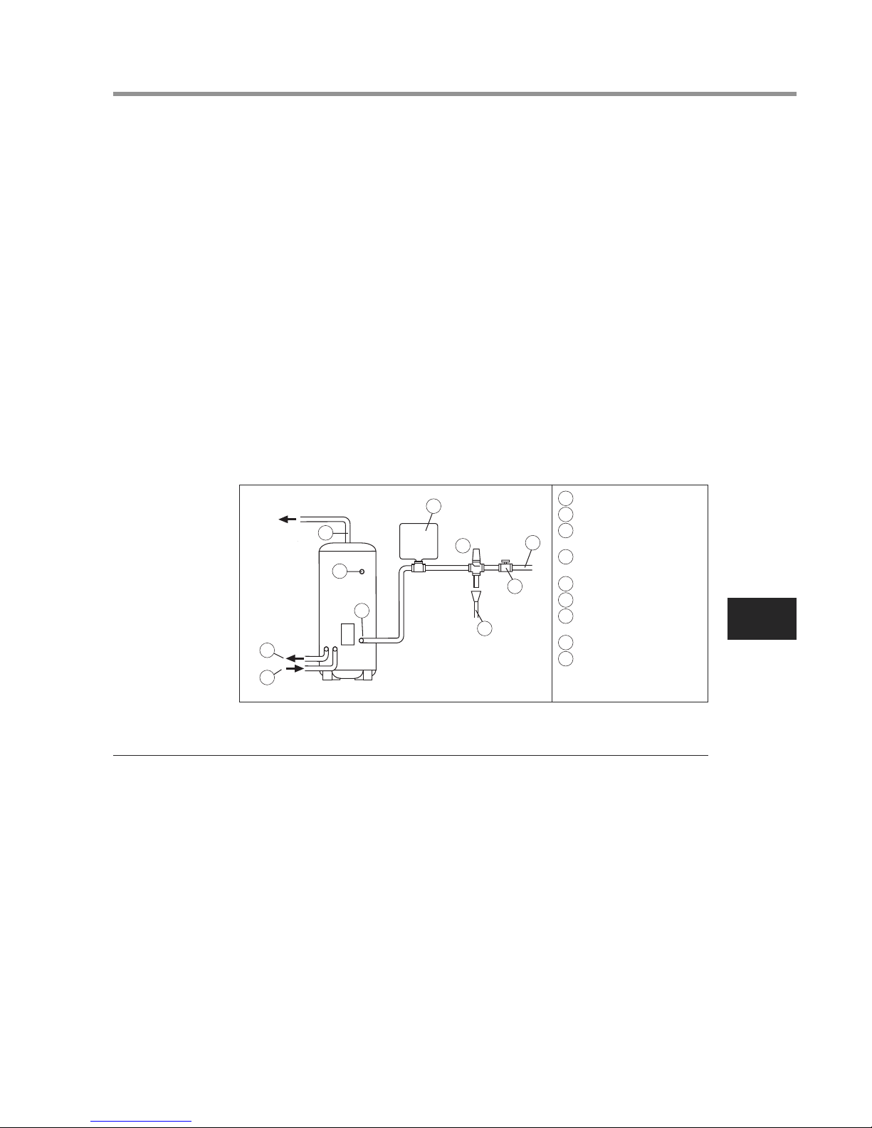
1
1 COLD WATER INLET
2 ISOLATING VALVE
3 SAFETY GROUP NF7 BAR
4 SANITARY WATER
EXPANSION VESSEL
5 DISCHARGE PIPE
6 PRIMARY CIRCUIT RETURN
7 PRIMARY CIRCUIT FLOW
8 HOT WATER OUTLET
9 SANITARY WATER
RE-CIRCULATION
CONNECTION
Diagram 2
AIR TO WATER HEAT PUMP SYSTEM INSTALLATION AND SERVICE MANUAL
7
EN
The cable to the thermal sensor must be routed through the left hand cable gland
provided and the outer sheath of the cable firmly secured by tightening the screw on
the cable gland. The sensor cable should be 0.75mm
2
2 core + shield (ground) with
a maximum current rating of 100mA. The cable should not be longer than 5 metres.
4.7 Replace the terminal cover before operating.
4.8 DO NOT heat the unit until the water cylinder has been completely filled with
water.
4.9 Thermal control of the water cylinder is done by the Hydro Unit controls. Refer to
the Air to Water Heat Pump Installation Manual for instructions for setting the hot
water storage temperature.
4.10 The electrical supply from the Air to Water Heat Pump to the cylinder heater
incorporates an over-temperature thermal cut-out that will switch off the cylinder
heater in the event of a thermal control failure. DO NOT bypass the thermal
cut-out in any circumstances.
5.0 COMMISSIONING
WARNING: Water that is left standing in a stainless steel water cylinder for long
periods without draw off will become de-oxygenated and potentially corrode
the vessel material. If the installation is to be left unused following installation
and commissioning the water cylinder should be drained or regularly (once per
week) flushed through with fresh mains water.
When placing the unit into service the procedure for filling the unit and the
system checks detailed below should be repeated.
5.1 DO NOT switch on the Air to Water Heat Pump until the unit has been filled with
water and checked for leaks.
5.2 Check that all installation, electrical and discharge pipe requirements have been
met.
5.3 Check that all water and electrical connections are correctly made and are tight.
5.4 Open a hot tap supplied by the unit, turn on the cold water supply to the unit.
5.5 Allow the unit to fill and leave the hot tap running for a short while to purge any
air and flush out the pipework. Close the hot tap.
5.6 Open successive hot taps to purge any air from the system.
5.7 With all hot taps closed, check the system for water leaks and rectify as necessary.
3
3
7
2
1
6
6
5
4
4
1
2
A
B
TBO6(TTW)
TBO3 (230V)
1 TO HYDRO UNIT
2 SENSOR
3 GREEN/YELLOW
4 BLUE
5 DOUBLE POLE THERMAL
CUT-OUT
6 BROWN
7 230V~ MAINS SUPPLY
FROM HYDRO UNIT.
1.5mm2MIN. CABLE SIZE
Diagram 3

AIR TO WATER HEAT PUMP SYSTEM INSTALLATION AND SERVICE MANUAL
8
EN
5.8 Manually test the operation of the Pressure Relief Valve. Ensure water flows
freely from the valve and through the discharge pipe.
5.9 Fill the primary circuit following the “Water Pipe” section in the Hydro Unit
Installation Manual. Vent any trapped air by opening the air bleed point or
automatic air vent.
5.10 Switch on the electrical supply to the Air to Water Heat Pump and ensure the
programmer is set to HOT WATER mode. Check that any motorised valves or
primary pumps are working and allow the unit to heat. The hot water temperature
may be varied using the Hydro Unit remote controller, for details refer to the Air to
Water Heat Pump Owners Manual.
6.0 MAINTENANCE –
DESCALING CYLINDER HEATER
6.1 Little maintenance is required, however in hard water areas the unit will require
periodic descaling to ensure efficient operation. To descale the unit:
6.2 Switch off and disconnect the electrical supply and shut down the heat pump.
Turn off the water supply to the unit.
6.3 Open a hot tap served by the unit to relieve any system pressure. Empty the unit
by opening the drain valve in the inlet pipework.
6.4 Open the terminal cover. Carefully remove the thermal sensor from its pocket on
the cylinder heater by pulling outwards.
6.5 Disconnect the link wires connecting the thermal cut-out to the cylinder heater.
Carefully remove the thermal cut-out sensing bulb from its pocket on the cylinder
heater by pulling outwards. Be careful not to kink the capillary tube.
6.6 Remove the element tail insulating shroud by pulling it outwards from the element.
6.7 Unscrew cylinder heater backnut. A key spanner is provided with the unit for
easy removal/tightening of the cylinder heater backnut. Remove the cylinder
heater from the unit. NOTE over time the cylinder heater gasket may become
stuck to the mating surface, to break the seal insert a round bladed screwdriver
into one of the pockets on the cylinder heater and gently lever up and down.
6.8 Carefully remove any scale from the surface of the element. DO NOT use a
sharp implement as damage to the element surface could be caused.
6.9 Ensure sealing surfaces are clean and seals are undamaged. If in doubt fit a
new gasket.
6.10 Replace cylinder heater ensuring the element tails are in the VERTICAL plane (see
Diagram 3). Secure in place by re-fitting cylinder heater backnut and tightening.
It may be helpful to support the cylinder heater using a round bladed screwdriver
inserted into one of the element pockets whilst the backnut is being tightened.
6.11 Replace the element tail insulating shroud by carefully pushing over the element
tails until it sits flush with the face of the element mounting plate.
6.12 Replace the thermal cut-out capillary in the LEFT HAND pocket of the cylinder
heater. Ensure it is fully inserted and that the capillary tube is not kinked.
Ensure the capillary tube is routed such that it does not come into contact with
the element tails.
AIR TO WATER HEAT PUMP SYSTEM INSTALLATION AND SERVICE MANUAL
9
EN
6.13 Replace the thermal sensor into the LEFT HAND pocket of the cylinder heater
behind the thermal cut-out. Ensure it is fully inserted, and the securing grommet
is pushed into the open end of the pocket.
6.14 Refit the cylinder heater wiring links by inserting the male terminations into the
female terminals on the element tails in accordance with Diagram 3. Check all
wiring terminations are tight and secure. Replace and secure the terminal cover.
6.15 DO NOT SWITCH ON EITHER THE AIR TO WATER HEAT PUMP OR CYLINDER
HEATER UNTIL THE UNIT HAS BEEN RE-FILLED WITH WATER. Re-commission
the unit following the Installation and COMMISSIONING instructions.
7.0 MAINTENANCE – SAFETY VALVES
7.1 The Pressure Relief Valve and any other safety valves fitted should be regularly
checked for correct operation.
7.2 Manually operate the valve(s) and ensure that water flows freely from the valve
and through the discharge pipe. NOTE: the water discharged may be very hot.
Ensure the valve re-seats correctly when released.
8.0 USER INSTRUCTIONS
8.1 The water storage temperature at the Air to Water Heat Pump System Water
Cylinder is set at the control panel of the Hydro Unit. This can be set to give
temperatures in the range of 40ºC to 75ºC, 60ºC is recommended. Refer to the
Hydro Unit Installation Manual for details of how to adjust the storage
temperature should this be necessary.
8.2 To avoid any risk of freezing when the cylinder is not in use for long periods
during the winter months, it is recommended that the Air to Water Heat Pump
primary supply and the cylinder heater are switched off and the water cylinder is
drained. NOTE: this will not protect other parts of the system pipework. If this is
done the water cylinder must be fully re-commissioned prior to switching on the
Air to Water Heat Pump and cylinder heater or damage may be caused.
8.3 To ensure the water cylinder continues to operate at its optimum performance it
should periodically be maintained in accordance with the instructions given under
the sections headed MAINTENANCE.
2
3
4
1
5
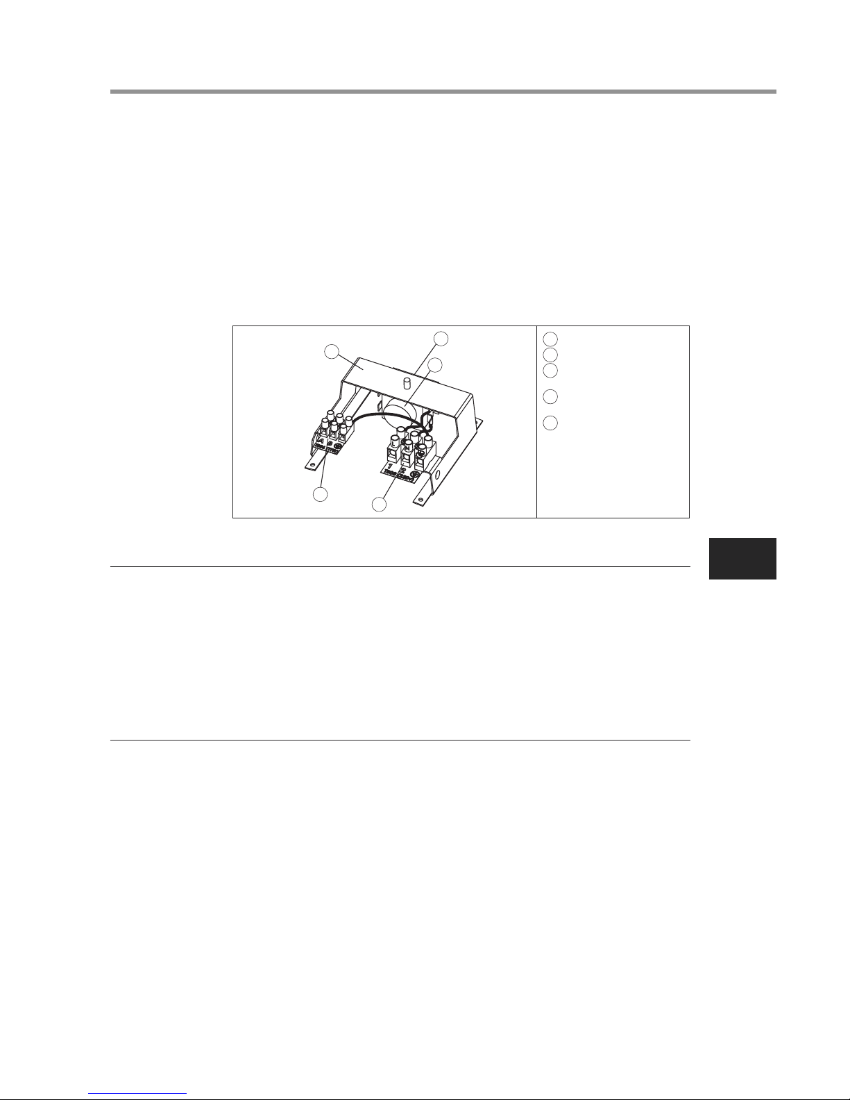
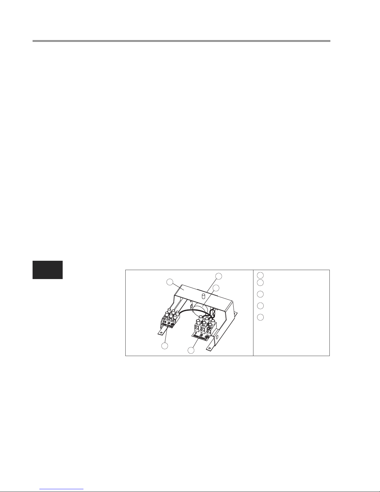
1 TERMINAL BRACKET
2 THERMAL CUT-OUT
3 SENSOR TERMINAL
BLOCK
4 MAINS TERMINAL
BLOCK
5 RESET BUTTON
LOCATED ON THIS FACE
NOTE:
THE COVER AND ELEMENT
ASSEMBLY HAVE BEEN
REMOVED FROM THIS VIEW
FOR CLARITY
Diagram 4

AIR TO WATER HEAT PUMP SYSTEM INSTALLATION AND SERVICE MANUAL
10
EN
8.4 IMPORTANT NOTES TO THE USER
• Do not block or restrict the discharge from any safety valve fitted.
• Do not tamper with any safety valve fitted.
• Do not bypass the thermal cut-out in any circumstances.
• If a fault is suspected contact a qualified engineer to check the system.
9.0 SPARE PARTS
9.1 The following list of spare parts is available for the Air to Water Heat Pump water
cylinder. Refer to the technical data label on the unit to identify the model
installed and to ensure the correct parts are ordered.
9.2 DO NOT replace with parts not recommended by the manufacturer as this will
invalidate your guarantee and may render the installation dangerous.
9.3 Description Part No.
Cylinder heater................................................................................95:606:967
Cylinder heater gasket.....................................................................95:611:012
Cylinder heater backnut...................................................................95:607:118
Cylinder heater key spanner............................................................95:607:119
Thermal cut-out (cylinder heater)....................................................95:612:038
Element tail insulating shroud..........................................................95:607:115
Terminal cover .................................................................................95:614:109
Terminal block (cylinder heater connection)....................................95:607:113
Terminal block (thermal sensor connection)....................................95:607:114
Thermal sensor................................................................................95:612:037
Set of compression nuts and olives.................................................95:607:116
Secondary re-circulation connection plug .......................................95:607:117
Safety Group ...................................................................................95:605:073
3
6
7
8
9
1
2
5
12
Diagram 5
1
2
3
5
6
7
8
9
12
AIR TO WATER HEAT PUMP SYSTEM INSTALLATION AND SERVICE MANUAL
11
EN
10.0 FAULT FINDING
The table below lists some common faults, their possible causes and their remedy. Any
servicing of the water cylinder and Air to Water Heat Pump system must be carried out
by a trained competent installer.
FAULT
No hot
water flow
Water from hot
taps is cold
Water from hot
taps is only
warm
Water from hot
taps is too hot
Water discharges
from Pressure
Relief Valve
continually
POSSIBLE CAUSE
1. Mains water supply off
2. Mains water filter
(if fitted) blocked
3. Inlet water control valves
incorrectly fitted
1. Controller on Heat Pump Hydro
Unit set to Space Heating only
2. Heat Pump not working
3. Faulty water cylinder temperature
sensor
1. Cylinder heater thermal cut-out
has operated
2. Faulty water cylinder temperature
sensor
1. Water storage temperature on
Heat Pump Controller is set too
high
2. Faulty water cylinder temperature
sensor
1. Mains water pressure too high
2. Pressure Relief Valve seat is
damaged
REMEDY
1. Check and turn on mains water
supply
2. Turn off water supply. Remove
filter and clean in accordance with
manufacturers instructions
3. Check and refit as required
1. Check setting
2. Check operation of Heat Pump.
If a fault is suspected consult the
Heat Pump Manual
3. Check sensor operation.
Replace if necessary
1. Check. Reset by pushing button on
cut-out
2. Check sensor operation. Replace if
necessary
1. Check and adjust as required
2. Check sensor operation.
Replace if necessary
1. Refer to section Important
Installation Points for correct
pressure. If necessary
fit a Pressure Reducing Valve
to inlet water supply
2. Remove and replace

AIR TO WATER HEAT PUMP SYSTEM INSTALLATION AND SERVICE MANUAL
12
EN
11.0 GUARANTEE
For warranty details please contact your ESTIA Heat Pump supplier.
This water cylinder is guaranteed provided that:
11.1 The unit has been installed in accordance with these instructions and all
necessary inlet controls and safety valves have been fitted correctly.
11.2 Any valves or controls are of the manufacturers recommended type.
11.3 The unit has not been tampered with and has been regularly maintained as
detailed in these instructions.
11.4 The unit has been used only for heating potable water (max. 250mg/l chloride).
11.5 The unit has not been subjected to high chloride levels in the water supply or
incorrect disinfection methods.
11.6 Following commissioning the unit is put into service within a period of 7 days.
If this is not the case it must either be drained or regularly flushed as required
in the section “Commissioning – Warning”.
11.7 The unit is NOT guaranteed against damage by frost or due to build up of scale.
11.8 This guarantee does not affect the statutory rights of the consumer.
This guarantee DOES NOT cover the ESTIA Air to Water Heat Pump Outdoor
Unit or ESTIA Hydro Unit.
12.0 ENVIRONMENTAL INFORMATION
12.1 This product is manufactured from many recyclable materials. At the end of its
useful life it should be disposed of at a Local Authority Recycling Centre to
realise the full environmental benefits.
12.2 The insulation material is CFC/HCFC free expanded polyurethane foam with an
ozone depletion factor of zero.
The pace of product development is such that we reserve the right to change product
specifications without notice. We do, however, strive to ensure that all information in this
leaflet is accurate at the time of publication.

AIR TO WATER HEAT PUMP SYSTEM INSTALLATION AND SERVICE MANUAL
13
EN
IMPORTANT INFORMATION AND WARNING
READ BEFORE INSTALLING THE UNIT. KEEP IN A SAFE PLACE. THE INFORMATION IN THE
FOLLOWING NOTES IS NEEDED FOR THE END OF LIFE DISPOSAL OR REUSE OF THE UNIT.
• We are very sensitive to the environment and welcome the 2002/96/EC WEEE
(Waste Electrical and Electronic Equipment) Directive.
• This product is compliant with EU Directive 2002/96/EC. It must be collected
separately after its use is completed and must not be disposed of as unsorted
municipal waste.
• The objectives of the EU Directive 2002/96/EC are to tackle the fast increasing
waste stream of electrical and electronic equipment, increase the recycling of
electric and electronic equipment (“EEE”), and to limit the total quantity of waste
EEE (“WEEE”) going to disposal.
• The crossed out wheeled bin symbol that is affixed to the product indicates that
this product may fall under the Directive.
• The user is responsible for returning the product to the appropriate collection
facility as specified by your municipality or the distributor. In case of installation of
a new product, it may be possible to have the distributor pick up old WEEE
directly.
• The producer, importer and distributor are responsible for collection and
treatment of WEEE, either directly or through a collective system. The distributor
for your country is shown below.
• In case of violation of the Directive, sanctions are set in each country.
• We are in general following the CECED interpretation which considers the
WEEE Directive applicable to Portable units, De-humidifiers, WRACs (Window
Room Air to Water Heat Pumps), Split systems up to 12kW, plug in refrigerators
and freezers.
• Nevertheless, there may be differences among various member state laws.
In cases where national laws exclude some products from the WEEE scope,
those laws must be followed. In countries where these products are not covered
by the WEEE scope the WEEE obligations do not have to be followed.
• The WEEE Directive does not apply to products sold outside the European
Community. In these cases the WEEE obligations do not have to be followed,
however compliance with any local regulations must be ensured.
• For additional information please contact the municipal facility, the
shop/dealer/distributor/installer that has sold the product, or the producer.

SYSTÈME DE POMPE À CHALEUR AIR-EAU
BALLON D’EAU DOMESTIQUE (NON
RACCORDÉ) FERMÉ EN SORTIE MÉTHODE DE CHAUFFAGE INDIRECTE
MANUEL D’INSTALLATION ET DE
RÉPARATION
IMPORTANT
VEUILLEZ LIRE ET COMPRENDRE CES INSTRUCTIONS AVANT D’INSTALLER
LE BALLON D’EAU. UNE INSTALLATION INCORRECTE PEUT ANNULER LA
GARANTIE. LE BALLON D’EAU DOIT ÊTRE INSTALLÉ PAR UN INSTALLATEUR
QUALIFIÉ SELON LES RÈGLES DE PLOMBERIE, DE CONSTRUCTION ET
ÉLECTRIQUES LOCALES. VEUILLEZ RANGER CE MANUELAVEC L’UNITÉ POUR
TOUTE CONSULTATION ULTÉRIEURE.
CARACTÉRISTIQUES TECHNIQUES
Pression nominale 1,0 MPa (10 bar)
Pression d’essai (hydraulique) 1,5 MPa (15 bar)
Pression d’alimentation minimale recommandée 0,1 MPa (1 bar)
Pression de travail du circuit principal 0,35 MPa (3,5 bar)
Puissance électrique (chauffe-ballon) 2,75 kW à 230 V~
Poids (plein) 150 litres indirect 181 kg
210 litres indirect 251 kg
300 litres indirect 360 kg
COMPOSANTS FOURNIS
• Ballon d’eau comprenant un chauffe-ballon électrique et des contrôles thermiques.
• Groupe de sécurité intégrant une soupape de surpression, une soupape de
vérification
(sans retour) et une soupape d’isolation.
• Écrous et olives de compression.
• Clé de chauffe-ballon.
SYSTÈME DE POMPE À CHALEUR AIR-EAU MANUEL D’INSTALLATION ET DE RÉPARATION
14
FR

1.0 POINTS IMPORTANTS CONCERNANT
L’INSTALLATION
1.1 Cet appareil, à utiliser avec le système de pompe à chaleur air/eau ESTIA, est
un cylindre à eau non raccordé conçu à cet effet.
1.2 Le ballon d'eau DOIT être équipé d'une soupape de surpression conforme aux
règlements locaux de plomberie et de construction. LE DÉFAUT DE
FOURNITURE D’UN DISPOSITIF DE DÉCOMPRESSION ADAPTÉ
ANNULERA TOUTE GARANTIE ET RENDRA L’INSTALLATION
DANGEREUSE.
1.3 Si la pression d’admission dépasse 0,6 MPa (6 bar), un détendeur de pression
(réglé à 0,5 MPa (5 bar) au maximum) doit être monté sur la ligne d’admission
du ballon d’eau. Il NE DOIT PAS être monté entre la soupape de décharge et le
ballon d’eau.
1.4 Un clapet de non-retour doit être monté sur la ligne d’alimentation du ballon d’eau.
Il NE DOIT PAS être monté entre la soupape de décharge et le ballon d’eau.
1.5 Cet appareil n'est pas destiné à un usage par des personnes (y compris les
enfants) à capacités physiques, sensorielles ou mentales réduites, ou ayant un
manque d'expérience ou de connaissances, à moins qu'ils bénéficient d'une
supervision ou d'instructions relatives à l'utilisation de l'appareil par une
personne responsable de leur sécurité. Les enfants doivent être surveillés pour
garantir qu'ils ne jouent pas avec l'appareil.
2.0 INSTALLATION - CONDITIONS GÉNÉRALES
2.1 Les règles nationales de câblage peuvent contenir des restrictions au sujet de
l’installation de ces unités dans certaines zones, par exemple. Salles de bains.
2.2 L’unité DOIT être installée verticalement.
2.3 L’unité doit être placée sur une surface de niveau.
2.4 Se référer au schéma 1 et au Tableau des dimensions pour déterminer une
position appropriée du ballon d’eau.
2.5 NOTE : assurez-vous que le plancher peut supporter le poids total de l’unité
(voir les CARACTÉRISTIQUES TECHNIQUES).
2.6 NE PAS installer dans un endroit où l’unité peut geler.
2.7 L’adduction d’eau peut ensuite fournir l’eau chaude et l’eau froide simultanément
en fonction des besoins. Il est conseillé d’évaluer la demande d’eau maximale et
de vérifier l’adduction d’eau pour faire en sorte que cette demande soit satisfaite.
REMARQUE : une pression élevée de l’adduction d’eau n’est pas toujours la
garantie d’un débit important. Nous suggérons une exigence minimale en termes
de pression d’adduction d’eau de 0,1 MPa (1,0 bar) et un débit de 20 litres par
minute. Toutefois, à ces valeurs, le débit de sortie peut être faible si plusieurs
sorties sont utilisées simultanément. Plus la pression et le débit disponibles sont
élevés, meilleure sera la performance du système.
2.8 LIMITES :
le ballon d’eau ne devrait pas être utilisé dans les situations suivantes :
• Lorsque la maintenance est susceptible d’être négligée ou les dispositifs de
sécurité endommagés.
SYSTÈME DE POMPE À CHALEUR AIR-EAU MANUEL D’INSTALLATION ET DE RÉPARATION
15
FR
• Lorsque l’adduction d’eau n’offre pas une pression satisfaisante ou peut être
intermittente.
• Lorsqu’il n’et pas possible d’évacuer les eaux usées des soupapes de
sécurité.
• Dans les régions où l’adduction d’eau contient régulièrement une proportion
élevée de solides ou de particules en suspension, sauf si un filtrage adéquat
peut être assuré au niveau de l’arrivée d’eau.
3.0 INSTALLATION - PLOMBERIE
3.1 Se référer à la section POINTS IMPORTANTS CONCERNANT
L’INSTALLATION. Montez les vannes selon la séquence indiquée par le
schéma 2. Assurez-vous que les vannes sont installées et orientées
correctement conformément aux directions des flèches de débit marquées sur
les vannes. Le ballon d'eau DOIT être équipé d'une soupape de surpression
conforme aux règlements locaux de plomberie et de construction (fournie par le
Groupe de sécurité). LE DÉFAUT DE FOURNITURE D’UN DISPOSITIF DE
DÉCOMPRESSION ADAPTÉ ANNULERA TOUTE GARANTIE ET RENDRA
L’INSTALLATION DANGEREUSE. Toute tuyauterie de décharge branchée à la
soupape de décharge doit être installée dans un sens descendant sans
interruption, dans un environnement sans gel.
3.2 Les raccordements d’eau sur l’unité acceptent la connexion directe des
tuyauteries de diamètre extérieur de 22 mm ; des écrous et olives sont fournis à
cette fin. Le filetage des raccordements est G3/4 pour permettre l’utilisation des
raccordements G3/4 si nécessaire. NE PAS utiliser de canalisations d’eau
enrobées de zinc. En cas d’utilisation de canalisations en acier, celles-ci doivent
être isolées de la cuve en acier inoxydable à l’aide de raccords diélectriques.
3.3 L’ADMISSION sanitaire de l’eau est marquée en BLEU, la SORTIE est
marquée en ROUGE. Plusieurs sorties chaudes peuvent être alimentées,
cependant, il faut considérer les différentes demandes en eau chaude du site
pour déterminer la capacité et le nombre de sorties à alimenter.
SYSTÈME DE POMPE À CHALEUR AIR-EAU MANUEL D’INSTALLATION ET DE RÉPARATION
16
FR
CAPACITÉ NOMINALE (litres)
A (mm)
B (mm)
C (mm)
D (mm)
SUPERFICIE (m²)
PRODUCTIOND'EAU CHAUDEÀ 60ºC (litres)
PRODUCTIOND'EAU CHAUDEÀ 40ºC (litres)
PERTE DECHALEUR (kWh/24h)
TEMPS DECHAUFFAGEDE15ºCÀ 60ºC –
AUMOYEN D'UN CHAUFFAGEÀ CYLINDRE
ÉLECTRIQUEUNIQUEMENT (minutes)
CAPACITÉCHAUFFÉE AU MOYEND'UN
CHAUFFAGE ÀCYLINDRE ÉLECTRIQUE
UNIQUEMENT(litres)
150 210 300
315 315 315
354 354 354
800 1184 1474
1090 1474 2040
0.65 0.79 0.79
102 163 254
243 329.5 476
1.45 1.91 2.52
123 188 262
102 163 254
Schéma 1
3.4 Recommandé qu’une vanne d’isolement soit montée sur l’alimentation d’eau
froide du ballon d’eau.
3.5 Un robinet de purge doit être monté au-dessous du ballon d’eau au niveau
de la canalisation d’admission. Il doit être placé entre le ballon d’eau et le clapet
anti-retour.
3.6 Un vase d’expansion du circuit sanitaire peut être monté sur l’alimentation en
eau froide selon les indications du schéma 2 pour éviter le gaspillage de l’eau
d’expansion. Les dimensions suivantes sont préconisées :
150 litres vase d’expansion de 12 litres
210 litres vase d’expansion de 18 litres
300 litres vase d’expansion de 24 litres
3.7 Un circuit de recyclage peut être installé sur le circuit d’eau sanitaire. Un
raccordement est fourni pour le tuyau de retour du circuit de recyclage (femelle
fileté G3/4).
3.8 E circuit de chauffage primaire DOIT être relié via Hydro Unit. Se référer aux
instructions d’installation fournies avec Hydro Unit pour des informations
détaillées complètes.
4.0 CARACTÉRISTIQUES ÉLECTRIQUES
4.1 L’unité est fournie avec un chauffe-ballon complet monté en usine avec un
détecteur thermique et le coupe-circuit de surchauffe. Le chauffe-ballon est
calibré sur 2,75 kW à 230 Vca.
4.2 Le chauffe-ballon est situé derrière le cache du terminal blanc sur l’avant de
l’unité. Le capot est fixé par 2 vis de chaque côté et par un écrou à dôme fileté
sur l’avant du capot. ISOLER L’ALIMENTATION ÉLECTRIQUE AVANT
D’ENLEVER LE CACHE.
4.3 Le chauffe-ballon DOIT être relié à la terre.
4.4 L’intégralité du câblage électrique doit être réalisée par un électricien compétent
et conformément aux plus récentes réglementations de câblage nationales. Le
circuit doit être protégé par un fusible approprié et un commutateur d’isolement
bipolaire avec une séparation des contacts supérieure à 3mm entre les deux
pôles.
4.5 Le chauffe-ballon doit être câblé selon le schéma 3 et le manuel d’installation de
pompe à chaleur. Le câble d’alimentation doit passer par le boîtier de commandes
SYSTÈME DE POMPE À CHALEUR AIR-EAU MANUEL D’INSTALLATION ET DE RÉPARATION
17
FR
1
4
3
2
5
6
8
9
7
1
1 ADMISSION D'EAU FROIDE
2 VANNE D’ISOLEMENT
3 GROUPE DE SÉCURITÉ NF
7 BARS
4 VASE D'EXPANSION DE
L'EAU SANITAIRE
5 TUYAU DE DÉCHARGE
6 FLUX DU CIRCUIT PRIMAIRE
7 RETOUR DU CIRCUIT
PRIMAIRE
8 SORTIE D'EAU CHAUDE
9 RACCORDEMENT DE
RECYCLAGE DE L'EAU
SANITAIRE
Schéma 2

de pompe à chaleur, la connexion directe au réseau électrique annulera la garantie
et pourrait rendre l’installation dangereuse. Le câble d’alimentation doit passer par
le presse-étoupe droit fourni et la gaine externe du câble fermement maintenue en
serrant la vis du presse-étoupe.
4.6 La sonde thermique doit être reliée au boîtier de commande de pompe à chaleur
selon le schéma 3 et le manuel d’installation de pompe à chaleur. Le câble de la
sonde thermique doit passer par le presse-étoupe de gauche fourni et la gaine
externe du câble fermement maintenue en serrant la vis sur le presse-étoupe.
4.7 Replacez le cache de la borne avant utilisation.
4.8 NE PAS mettre l’unité en chauffe tant que le ballon d’eau n’a pas été
complètement rempli d’eau.
4.9 Le contrôle thermique du ballon d’eau est assuré par les commandes de l’Hydro
Unit. Reportez-vous au Guide d’installation de la pompe à chaleur air-eau pour
obtenir des instructions concernant le réglage de la température d’eau de
stockage.
4.10 L’alimentation électrique de la pompe à chaleur au chauffe-ballon incorpore un
coupe-circuit thermique de surchauffe qui coupe le chauffe-ballon en cas de
défaillance du contrôle de température. NE PAS court-circuiter le coupe-circuit
thermique, en aucune circonstance.
5.0 MISE EN SERVICE
ATTENTION : de l’eau laissée stagnante dans un ballon d’eau en acier
inoxydable pendant de longues périodes sans être purgée peut se désoxygéner
et potentiellement corroder le matériau du réservoir. Si l’installation doit rester
inutilisée après l’installation et la mise en route, le ballon d’eau doit être vidangé
ou régulièrement purgé (une fois par semaine) via l’alimentation en eau fraiche.
Lors de la mise en place de l’unité, la procédure relative à son remplissage et
aux contrôles du système détaillée ci-dessous doit être répétée.
5.1 NE PAS mettre sous tension la pompe à chaleur tant que l’unité n’a pas été
remplie d’eau et examinée pour déceler les fuites.
5.2 Contrôlez que toutes les conditions d’installation, électriques et de décharge ont
été respectées.
5.3 Contrôlez que tous les raccordements hydrauliques et électriques sont
correctement réalisés et sont serrés.
5.4 Ouvrez un robinet d’eau chaude fournie par l’unité, ouvrez l’eau froide fournie
à l’unité.
SYSTÈME DE POMPE À CHALEUR AIR-EAU MANUEL D’INSTALLATION ET DE RÉPARATION
18
FR
3
3
7
2
1
6
6
5
4
4
1
2
A
B
TBO6(TTW)
TBO3 (230V)
1 VERS LE SYSTÈME DE
POMPE À CHALEUR
2 SONDE
3 VERT/JAUNE
4 BLEU
5 COUPE-CIRCUIT
THERMIQUE BIPOLAIRE
6 MARRON
7 ALIMENTATION RÉSEAU
13 AMPÈRES 1,5 mm
2
DIAMÊTRE DE CÂBLE MINI
Schéma 3

5.5 Laissez l’unité se remplir et laissez le robinet d’eau chaude couler pendant un
moment pour purger l’air et nettoyer la tuyauterie. Refermez le robinet d’eau
chaude.
5.6 Ouvrez les robinets d’eau chaude successivement pour purger tout l’air du système.
5.7 Avec tous les robinets d’eau chaude fermés, examinez le système pour déceler
des fuites d’eau et les colmater si nécessaire.
5.8 Testez manuellement le fonctionnement de la soupape de décharge. Assurez-vous
que l’eau s’écoule librement de la vanne et à travers la tuyauterie de décharge.
5.9 Remplissez le circuit primaire conformément à la section “Canalisation d’eau”
du Guide d’installation de l’Hydro Unit. Évacuez l’air éventuellement piégé en
ouvrant la purge d’air ou la ventilation automatique.
5.10 Mettez sous tension l’alimentation de la pompe à chaleur et assurez-vous que
le programmateur est réglé sur le mode EAU CHAUDE. Vérifiez que toutes les
vannes motorisées ou pompes primaires fonctionnent et permettent à l’unité
de chauffer. La température de l’eau chaude peut être modulée à l’aide de la
télécommande de l’Hydro Unit. Pour plus de détails, reportez-vous au Guide
du propriétaire de la pompe à chaleur air-eau.
6.0 MAINTENANCE - DÉTARTRAGE DU
CHAUFFE-BALLON
6.1 Peu d’entretien est nécessaire, toutefois dans des zones où l’eau est calcaire,
l’unité exige un détartrage périodique pour assurer un fonctionnement efficace.
Pour détartrer l’unité :
6.2 Éteignez et débranchez l’alimentation électrique et arrêtez la pompe à chaleur.
Coupez l’approvisionnement en eau à l’unité.
6.3 Ouvrez un robinet d’eau chaude fournie par l’unité pour relâcher toute pression du
système. Purgez l’unité en ouvrant la soupape de vidange au niveau de la
canalisation d’admission.
6.4 Ouvrez le cache des bornes. Déconnectez les fils reliant le coupe-circuit thermique
au chauffe-ballon. Enlevez soigneusement la sonde thermique de son
emplacement sur le chauffe-ballon en la tirant vers l’extérieur.
6.5 Enlevez soigneusement le coupe-circuit thermique détectant l’ampoule de
l’emplacement sur le chauffe-ballon en le tirant vers l’extérieur. Faites attention à ne
pas entortiller le tube capillaire.
6.6 Enlevez la monture isolante de l’élément en la tirant vers l’extérieur de l’élément.
6.7 Dévissez le contre-écrou du chauffe-ballon. Une clé est fournie avec l’unité pour
faciliter le déplacement/le serrage du contre-écrou du chauffe-ballon. Enlevez le
chauffe-ballon de l’unité. Sachez qu’avec le temps, le joint du chauffe-ballon peut
adhérer à la surface de contact. Pour casser le joint, insérez un tournevis à lames
rond dans l’un des emplacements sur le chauffe-ballon et soulevez-le doucement à
l’aide d’un levier par des mouvements oscillants.
6.8 Enlevez soigneusement toute trace de calcaire de la surface de l’élément. NE PAS
utiliser d’outil pointu qui pourrait endommager la surface de l’élément.
SYSTÈME DE POMPE À CHALEUR AIR-EAU MANUEL D’INSTALLATION ET DE RÉPARATION
19
FR
6.9 Assurez-vous que les surfaces d’étanchéité sont propres et les joints intacts.
En cas de doute, montez un nouveau joint.
6.10 Remettez le chauffe-ballon en vous assurant que les tiges de l'élément se situent
dans le plan VERTICAL (vois schéma 3). Fixez en place en remettant le
contre-écrou du chauffe-ballon et en le serrant. Il peut être utile de soutenir le
chauffe-ballon à l’aide d’un tournevis à lames rond inséré dans l’un des
emplacements de l’élément pendant le serrage du contre-écrou.
6.11 Replacez la monture isolante de tige d’élément en poussant soigneusement sur
des tiges jusqu’à ce qu’elle repose à affleurement sur la surface du support de
montage de l’élément.
6.12 Remplacez le tube capillaire de coupure thermique dans la poche GAUCHE du
chauffe-ballon.Assurez-vous qu’il est parfaitement inséré et que le tube capillaire
n’est pas tordu. Vérifiez que le tube capillaire est orienté de telle manière qu’il
n’entre pas en contact avec les rejets de l’élément.
6.13 Replacez le capteur thermique dans la poche GAUCHE du chauffe-ballon, en aval
de la coupure thermique.Assurez-vous qu’il est parfaitement inséré et que le guide
de sécurité pénètre dans l’extrémité ouverte de la poche.
6.14 Repositionnez les câbles du chauffe-ballon en insérant les terminaisons mâles
dans les terminaisons femelles sur les tiges de l’élément selon le schéma 3 Vérifiez
que toutes les terminaisons de câblage sont serrées et bloquées. Replacez et fixez
le cache des bornes.
6.15 NE PAS BRANCHER LA POMPE À CHALEUR OU LE CHAUFFE-BALLON
TANT QUE L’UNITÉ N’A PAS ÉTÉ REMPLIE D’EAU. Remettez l’unité en service
en suivant les instructions d’installation et de MISE EN SERVICE.
SYSTÈME DE POMPE À CHALEUR AIR-EAU MANUEL D’INSTALLATION ET DE RÉPARATION
20
FR
2
3
4
1
5
1 SUPPORT DE BORNES
2 COUPE-CIRCUIT
THERMIQUE
3 BORNIER
DE LA SONDE
4 BORNIER
D’ALIMENTATION
5 BOUTON DE RÉINITIALISATION
SITUÉ SUR CETTE SURFACE
NOTE:
LE COUVERCLE ET L'ÉLÉMENT
ONT ÉTÉ ENLEVÉS DE CETTE
VUE POUR PLUS DE CLARTÉ
Schéma 4

7.0 MAINTENANCE - SOUPAPES DE SÛRETÉ
7.1 La soupape de décharge et toutes les autres soupapes de sûreté montées
doivent être régulièrement examinées pour assurer un fonctionnement correct.
7.2 Actionnez manuellement les vannes et assurez-vous que l’eau s’écoule
librement de la vanne et à travers la tuyauterie de décharge. REMARQUE :
l’eau déchargée peut être très chaude. Assurez-vous que la vanne se
repositionne correctement une fois libérée.
8.0 INSTRUCTIONS D’UTILISATEUR
8.1 La température de stockage de l’eau dans le ballon d’eau du système de pompe
à chaleur air-eau est réglée sur le panneau de commande de l’Hydro Unit. On peut
la régler de manière à obtenir une température située entre 45ºC et 75ºC ; la
température recommandée est de 60ºC. Reportez-vous au Guide d’installation
de l’Hydro Unit pour plus de détails sur le réglage de la température de stockage
au besoin.
8.2 Pour éviter les risques de gel lorsque le chauffe-ballon reste inutilisé pendant de
longues périodes au cours des mois d’hiver, il est recommandé de déconnecter
l’alimentation primaire de la pompe à chaleur et le dispositif chauffant à
immersion, puis de vidanger le ballon d’eau . REMARQUE : cela ne protège pas
les autres éléments du réseau de canalisations. Si vous faites cela, le ballon
d’eau devra être entièrement remis en service avant la mise en marche de la
pompe à chaleur et du dispositif de chauffage à immersion ; dans le cas
contraire, le système pourrait être endommagé.
8.3 Afin de garantir le niveau de fonctionnement optimal du ballon d’eau, il doit
régulièrement être entretenu selon les instructions indiquées dans les différentes
sections MAINTENANCE.
8.4 NOTES IMPORTANTES À DESTINATION DE L’UTILISATEUR
• Ne bloquer ou limiter la décharge d’aucune soupape de sûreté montée.
• Ne manipuler aucune soupape de sûreté montée.
• Ne court-circuiter le coupe-circuit thermique en aucune circonstance.
• Si un défaut est suspecté, contacter un technicien qualifié pour
contrôler le système.
SYSTÈME DE POMPE À CHALEUR AIR-EAU MANUEL D’INSTALLATION ET DE RÉPARATION
21
FR
9.0 PIÈCES DE RECHANGE
9.1 La liste suivante de pièces de rechange est disponible pour le ballon d’eau à
pompe à chaleur. Référez-vous à l’étiquette des caractéristiques techniques
située sur l’unité pour identifier le modèle installé et pour vous assurer que les
pièces correctes sont commandées.
9.2 NE remplacez PAS par des pièces non recommandées par le fabricant car ceci
annulerait votre garantie et rendrait l’installation dangereuse.
9.3 Description N° de pièce
Chauffe-ballon.................................................................................95:606:967
Joint de chauffe-ballon.....................................................................95:611:012
Contre-écrou de chauffe-ballon.......................................................95:607:118
Clé de chauffe-ballon.......................................................................95:607:119
Coupe-circuit thermique (chauffe-ballon)........................................95:612:038
Monture isolante de tige d’élément .................................................95:607:115
Cache de bornes.............................................................................95:614:109
Bornier (raccordement du chauffe-ballon).......................................95:607:113
Bornier (raccordement de la sonde thermique)...............................95:607:114
Sonde thermique.............................................................................95:612:037
Ensemble d’écrous et d’olives de compression..............................95:607:116
Prise secondaire de raccordement de recyclage............................95:607:117
Groupe de sécurité..........................................................................95:605:073
SYSTÈME DE POMPE À CHALEUR AIR-EAU MANUEL D’INSTALLATION ET DE RÉPARATION
22
FR
3
6
7
8
9
1
2
5
12
Schéma 5
1
2
3
5
6
7
8
9
12
 Loading...