

Page 1
VAPOR
EstesRockets.com
MODEL ROCKET INSTRUCTIONS
KEEP FOR FUTURE REFERENCE
IMPORTANT: Please record date found on decal and keep for future reference. ______________
READ ALL INSTRUCTIONS. Make sure you have all parts and supplies. Test fit all parts before applying glue.
SUPPLIES
TM
7294
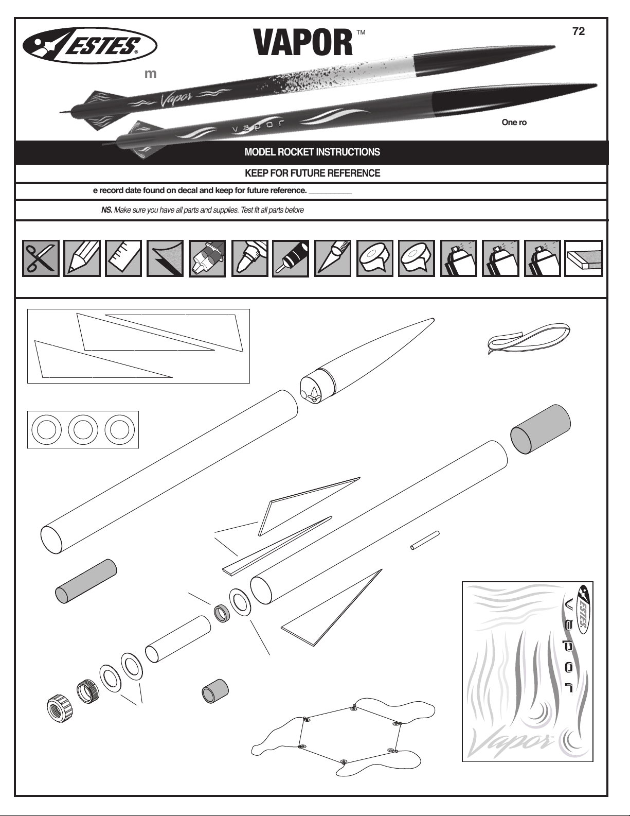
One rocket — two looks!
Decals included for both!
SCISSORS
090051-7294
Laser cut balsa sheet
C 090052-7294
Laser cut centering rings
PENCIL
FINE SANDPAPER
RULER CARPENTER’S
EPOXY
E
E
030164-2
B
Green engine block
M
034997
Yellow spacer tool
GLUE
PLASTIC CEMENT
D
030396
Body tube
HOBBY KNIFE
MASKING TAPE
I
072305
Nose cone
E
CLEAR TAPE
F
038166
Launch lug
PRIMER (WHITE)
H
038363
Shock cord
D
030396
Body tube
©2019 Estes Industries, LLC
All rights reserved. Made in Guangdong, China. PN 090001-7294 (7-19)
CLEAR COAT
(OPTIONAL)
PAINT (BLACK)
PAINT (YELLOW
OR PURPLE)
G
031777
Red tube coupler
SAND BLOCK
L
K
072417
Engine
retainer set
A 030463
Engine mount tube
N
035005
C
Orange E to D engine spacer
C
J
035802
Parachute
1
090001-7294
Waterslide decal
Page 2
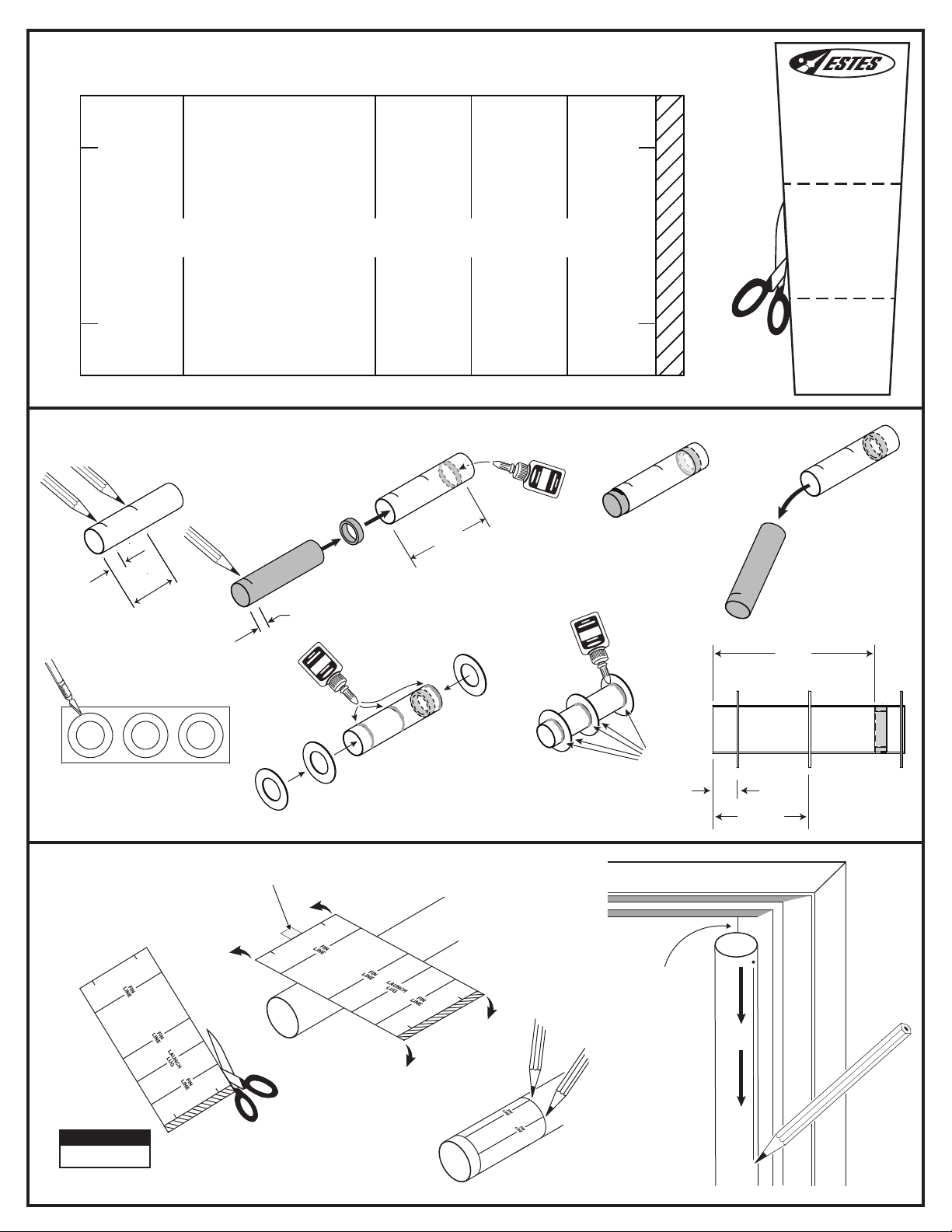
TUBE MARKING GUIDE & SHOCK CORD MOUNT
Make a copy if you want to keep instructions.
3
FIN
LINE
ASSEMBLE ENGINE MOUNT
Measure and
1.
mark
A.
2.
A
1/2”
(13 mm)
2”
(5.1 cm)
5.
FIN
LINE
Measure and mark M (yellow spacer
M (yellow spacer tool) to insert
tool). Use
B (green engine block) into position.
M
3/8”
(10 mm)
B
A
LAUNCH
LUG
3”
(7.6 cm)
FIN
LINE
INSERT M TO MARK.
7.
3.
LET DRY
4.
QUICKLY
3 3/8”
(8.6 cm)
REMOVE
M
C C
2
1
A
C
MARK TUBE
1.
NOTE:
Cut from above.
2.
C
Masking tape.
6.
C
A
GLUE
FILLETS
C
1/2”
(13 mm)
2”
(5.1 cm)
SIDE VIEW
OF ENGINE MOUNT
D
DOOR FRAME
Remove
4.
guide. Use
door frame
to extend
all lines.
3.
2
Page 3
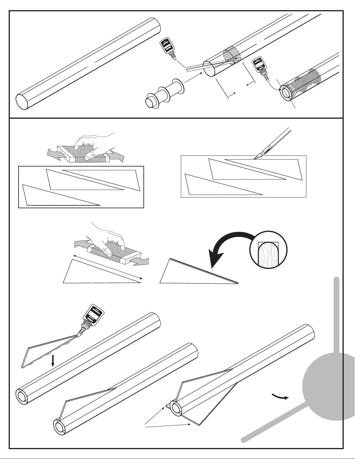
INSERT ENGINE MOUNT
ENDS EVEN
1.
2. Apply glue inside D.
Insert the engine mount.
D
PREPARE AND ATTACH FINS
1.
Sand both sides.
3. Apply ring of glue
D
2”
(5.1 cm)
to inside of
D and C meet.
C
D,where
2.
E
E
3.
ROUND LEADING EDGE
E
X3
4.
E
6.
5.
CHECK ALIGNMENT
LET DRY
Repeat for
remaining fins.
3
Page 4
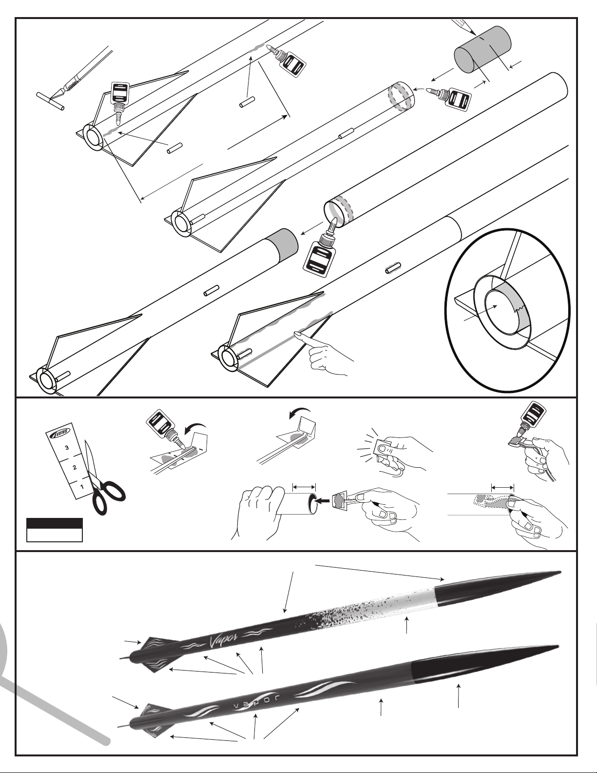
INSTALL LAUNCH LUGS AND UPPER BODY TUBE
1. Cut F in half.
2.
3. Mark middle of G.
Insert to mark and let dry.
1 1/2”
(3.8 cm)
G
F
12”
(30.5 cm)
F
F
4.
5.
Apply glue fillets to all joints.
Smooth with finger.
Let dry.
A
WRAP
MASKING TAPE
AROUND END OF
PROTECT SURFACE FROM
PRIMER AND PAINT.
A TO
INSTALL SHOCK CORD
2.
3.
1.
L
6. Glue shock cord
mount to the inside of
NOTE:
Cut from page 1.
ROCKET FINISHING — ONE ROCKET WITH TWO LOOKS
1. Spray rocket with white primer, let dry, and sand. Repeat until rocket is smooth,
then paint. Apply decals only after paint is dry.
2. Cut decals from sheet, trimming close to edge.
3. One at a time, place in warm water until decal curls and begins to relax.
4. Remove and position on rocket, sliding decal away from backing material.
There are two design styles to choose from.
5. Blot with clean paper towel. Let set overnight.
6. OPTIONAL: Apply protective clear coat.
DECAL
DECAL
D.
DECAL
1 1/2” (3.8 cm)
D
BLACK PAINT
4. Hold until set.
YELLOW PAINT
5. Apply glue to
shock cord
mount.
7.
1 1/2” (3.8 cm)
Use finger to hold
until glue sets.
DECAL
PURPLE PAINT
BLACK PAINT
4
Page 5
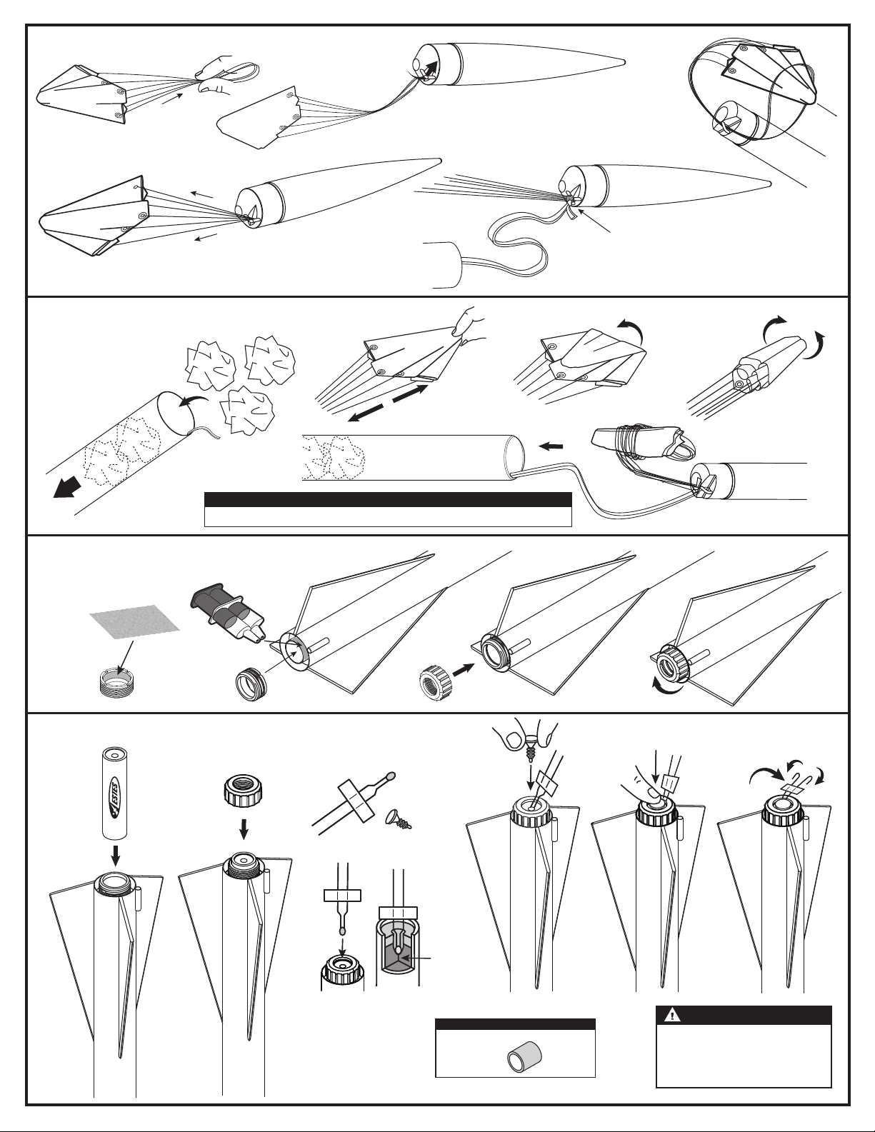
ATTACH PARACHUTE
1.
J
4.
2.
I
3.
5.
DOUBLE KNOT
D
H
PREPARE RECOVERY SYSTEM
1.
Push recovery
wadding down
towards end of
body tube.
INSTALL ENGINE RETAINER
Rough up inside surface
1.
of
K with sandpaper.
K
2.
3.
J
5.
D
NOTE:
Recovery wadding and parachute must slide easily into body tube. If too tight, redo.
Attach K with epoxy. Mix and apply
2.
according to epoxy instructions.
Let dry.
K
LET DRY
L
3.
4.
I
Wrap lines loosely.
4.
PREPARE ENGINE
1.
®
2.
4.
4.
3.
3.
STARTER
STARTER
Use 1 each.
Use 1 each.
5. 6.
PLUG
PLUG
TIP MUST
TIP MUST
TOUCH
TOUCH
PROPELLANT!
PROPELLANT!
NOTE:
If you are using a D engine, insert orange
spacer, then engine.
5
N
035005
7.
WARNING: FLAMMABLE
To avoid serious injury, read instructions & NAR
Safety Code included with engines. PREPARE YOUR
ENGINE ONLY WHEN YOU ARE OUTSIDE AT THE
LAUNCH SITE PREPARING TO LAUNCH. If you do
not use your prepared engine, remove the starter
before storing your engine.
Page 6
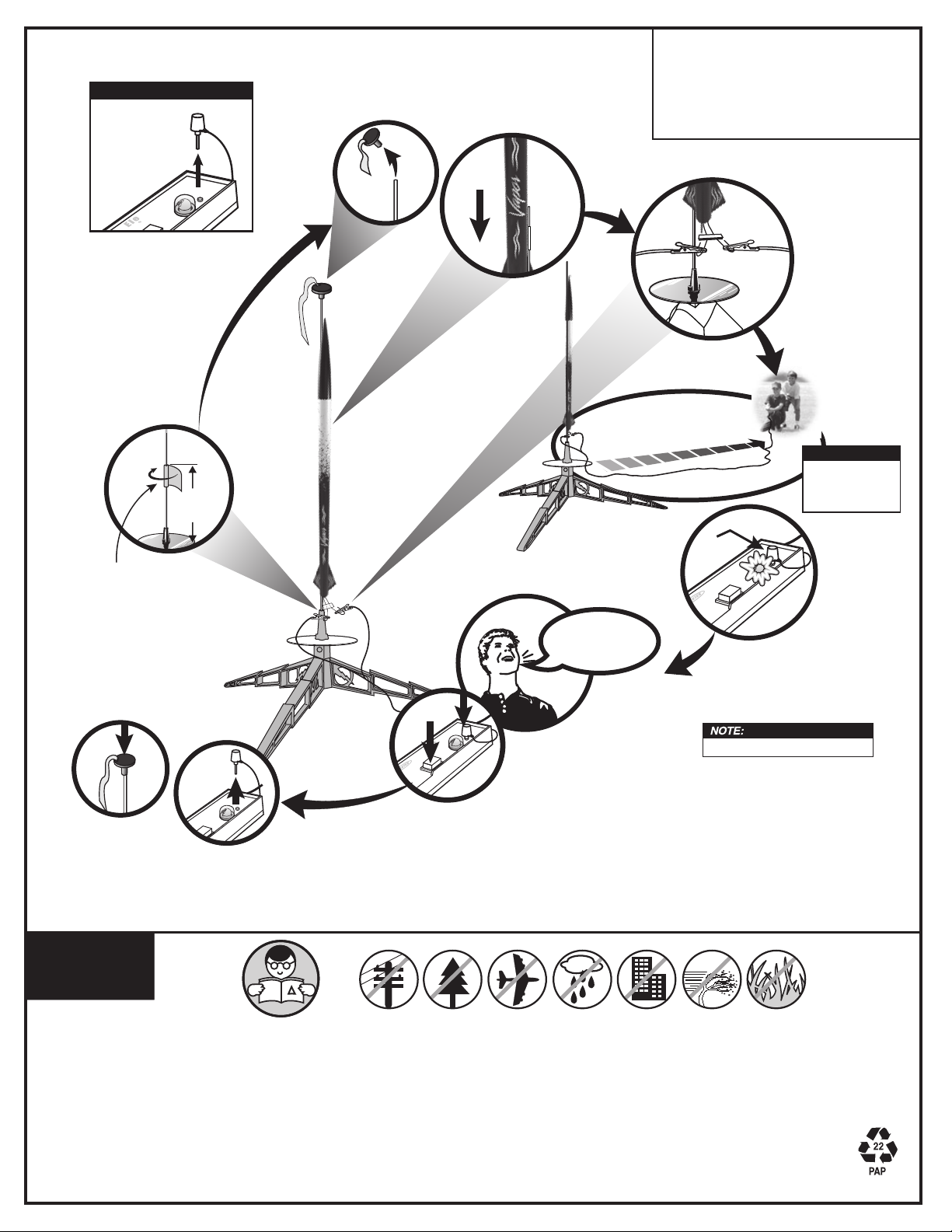
COUNTDOWN AND LAUNCH
NOTE:
Key always out until
final countdown!
1.
4”
(10.2 cm)
2.
3.
ESTES® LAUNCH SUPPLIES NEEDED
(Sold Separately)
• Porta-Pad
• E Launch Controller or Pro Series II Launch Controller
• Requires 3/16 in. (5 mm) Maxi TM Launch Rod
• Recovery Wadding
• Starters (with engines)
• Plugs (with engines)
• Estes® Engines: D12-5 (first launch), E12-6
® E Launch Pad
4.
5.
30 ft. (9.1 m)
NOTE:
Fully extend your
launch controller wire
before launching.
6.
KEY
MASKING TAPE
Re-cap rod.
10.
PRECAUTIONS
9.
NAR
SAFETY CODE
8.
7.
4...
2...
1...
3...
While holding key down FIRMLY,
press launch button until LIFTOFF!
Insert key, push down
hard. Bulb will light.
Estimated weight: 3.5 oz. (99.2 g)
NO DRY
GRASS OR WEEDS
PRE-LAUNCH CHECK For safety, never launch a damaged rocket. Check the rocket's body, nose cone and fins. Also, check the engine mount, recovery system and launch lug(s).
Repair any damage before launching the rocket.
FLYING YOUR ROCKET Choose a large field (500 ft. [152 m] square) free of dry weeds and brown grass. The larger the launch area, the better your chance of recovering your rocket.
Football fields and playgrounds are great. Launch only with little or no wind and good visibility. Always follow the National Association of Rocketry (NAR) SAFETY CODE (enclosed).
MISFIRES TAKE THE KEY OUT OF THE CONTROLLER. WAIT ONE MINUTE BEFORE GOING NEAR THE ROCKET. Disconnect the micro-clips and remove the engine. Take the
plug and starter out of the engine. A burned starter means the starter tip was not touching engine propellent. Install a new starter; be sure the tip is touching propellant inside the engine.
Push the plug in place. Repeat steps under Countdown and Launch.
© 2019 Estes Industries, LLC. All rights reserved.
Estes Industries, LLC, 1295 H Street, Penrose, CO 81240-9698. Made in Guangdong, China.
6
PN 090004-7294 (10-19)
 Loading...